
Transient Flow Evolution of a Hypersonic Inlet/Isolator with Incoming Windshear


Abstract
:1. Introduction
2. Introduction of the Hypersonic Inlet/Isolator and the Wind Shear Model
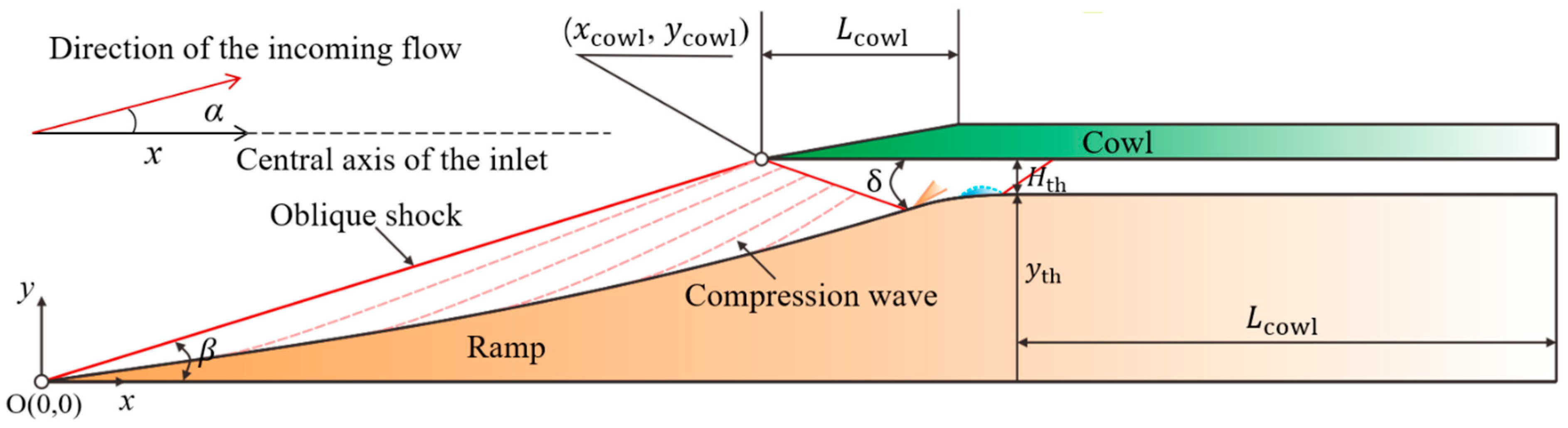
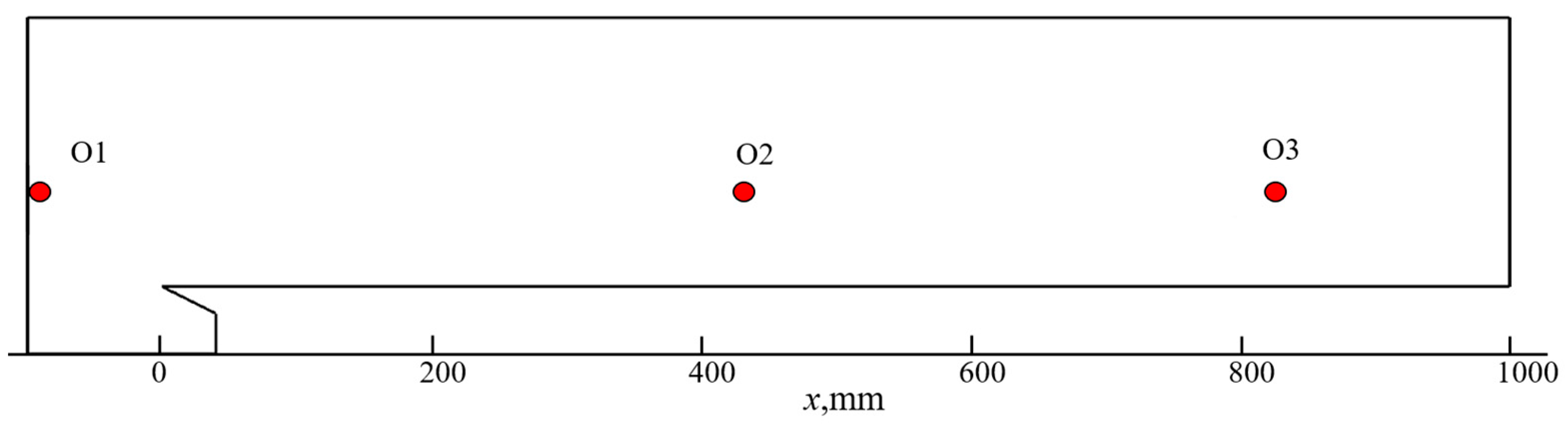
2.1. Description of the Hypersonic Inlet/Isolator
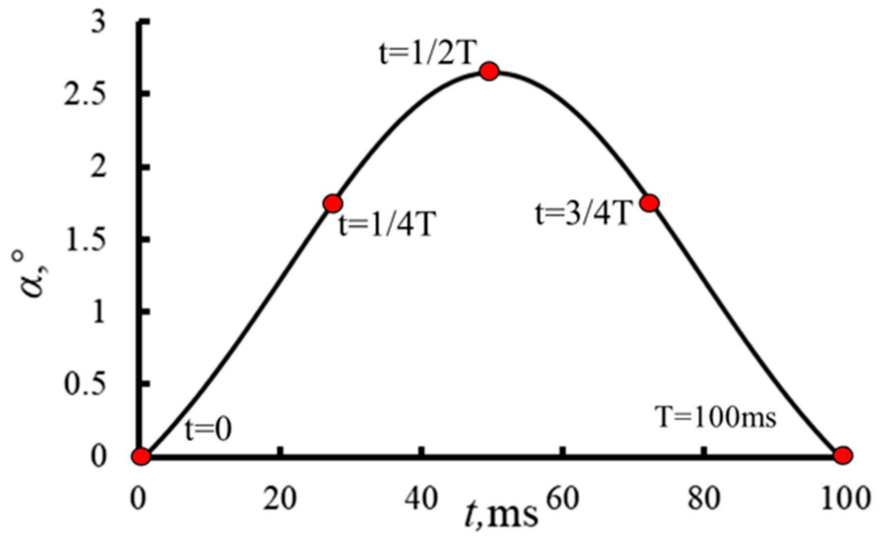
2.2. Model for the Wind Shear
3. Numerical Method
3.1. Computational Method
3.2. Grid Generation
3.3. Boundary Conditions
3.4. Inlet/Isolator Performance Parameters
- (1)
- The total pressure recovery coefficient (TPR) is the ratio of total pressure at the inlet/isolator exit (Pout*) to the freestream total pressure (P∞*). The total pressure loss is the sum of shock and viscous losses. The total pressure at the exit is calculated with the mass-weighted average.
- (2)
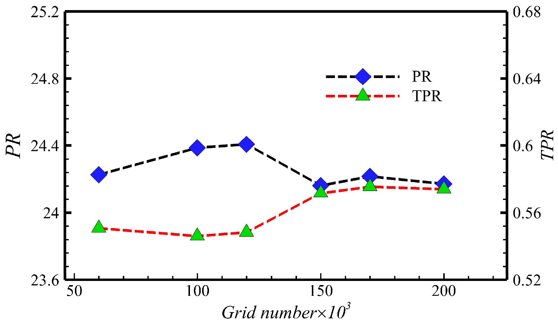
- The pressurization rate (PR) is one of the main indicators that characterize the compression characteristics of the inlet/isolator. It is defined as the ratio of inlet/isolator exit static pressure (Pout) to inlet/isolator static pressure (P∞). The static pressure at the exit is calculated with the mass-weighted average.
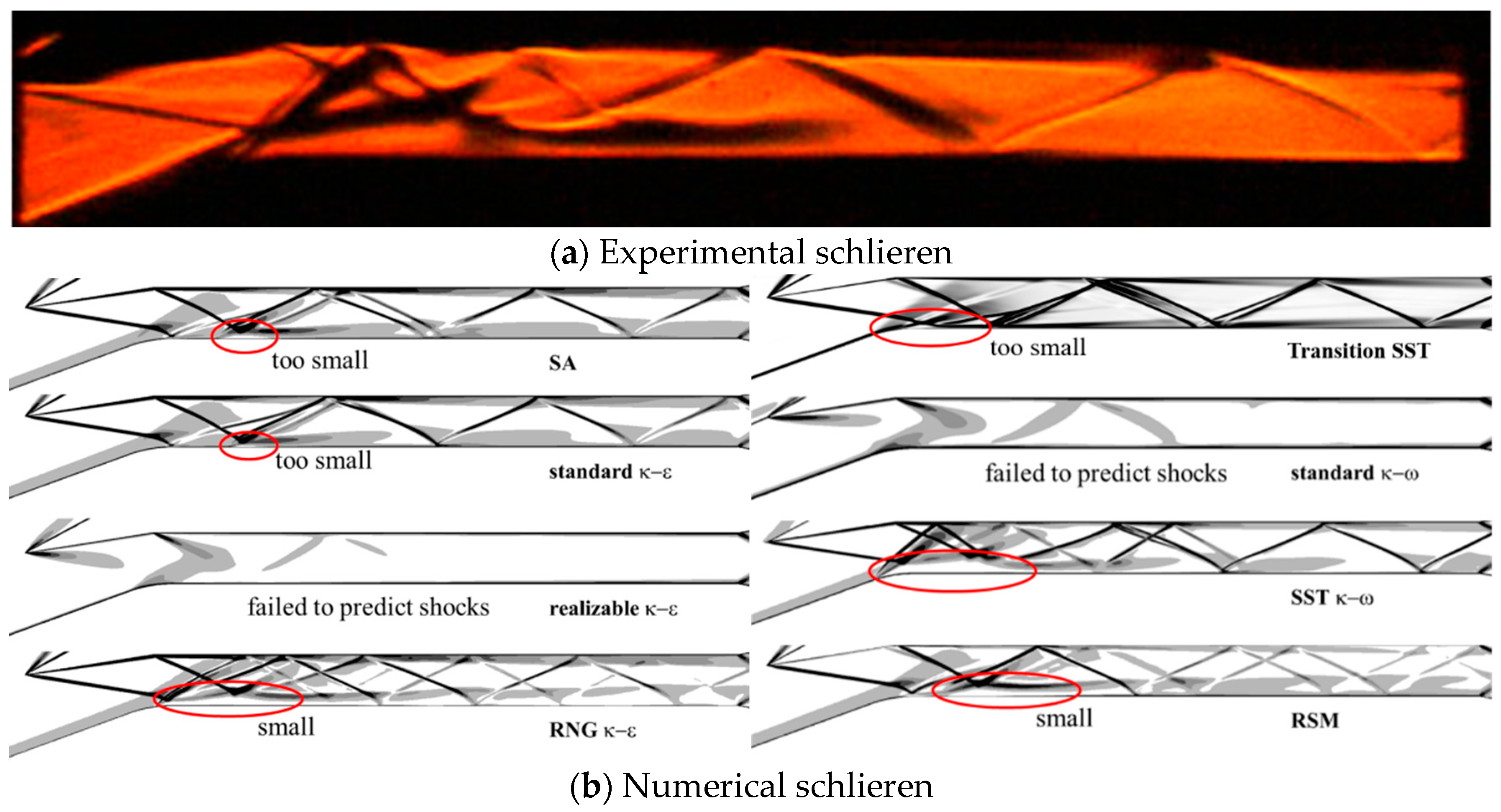
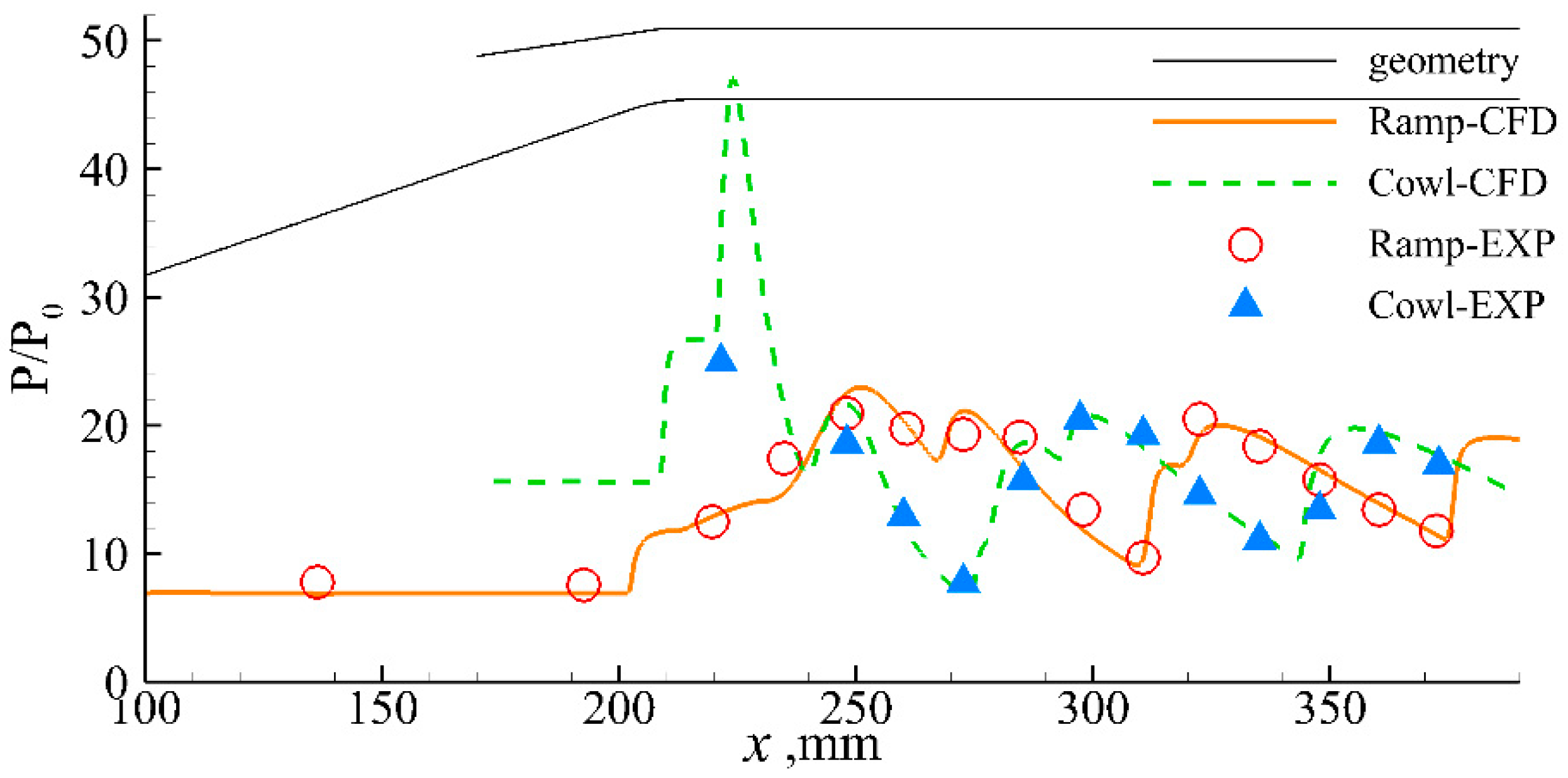
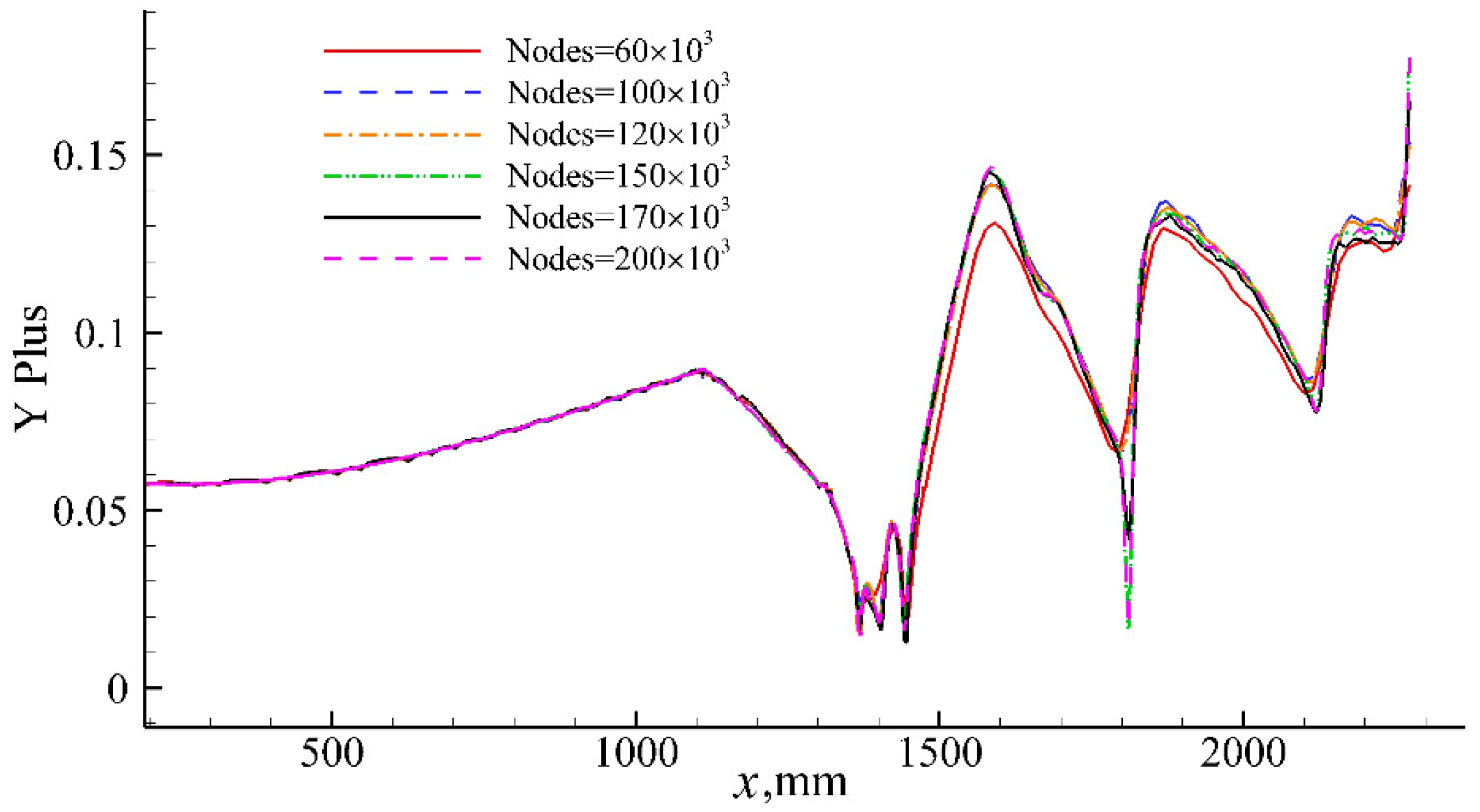
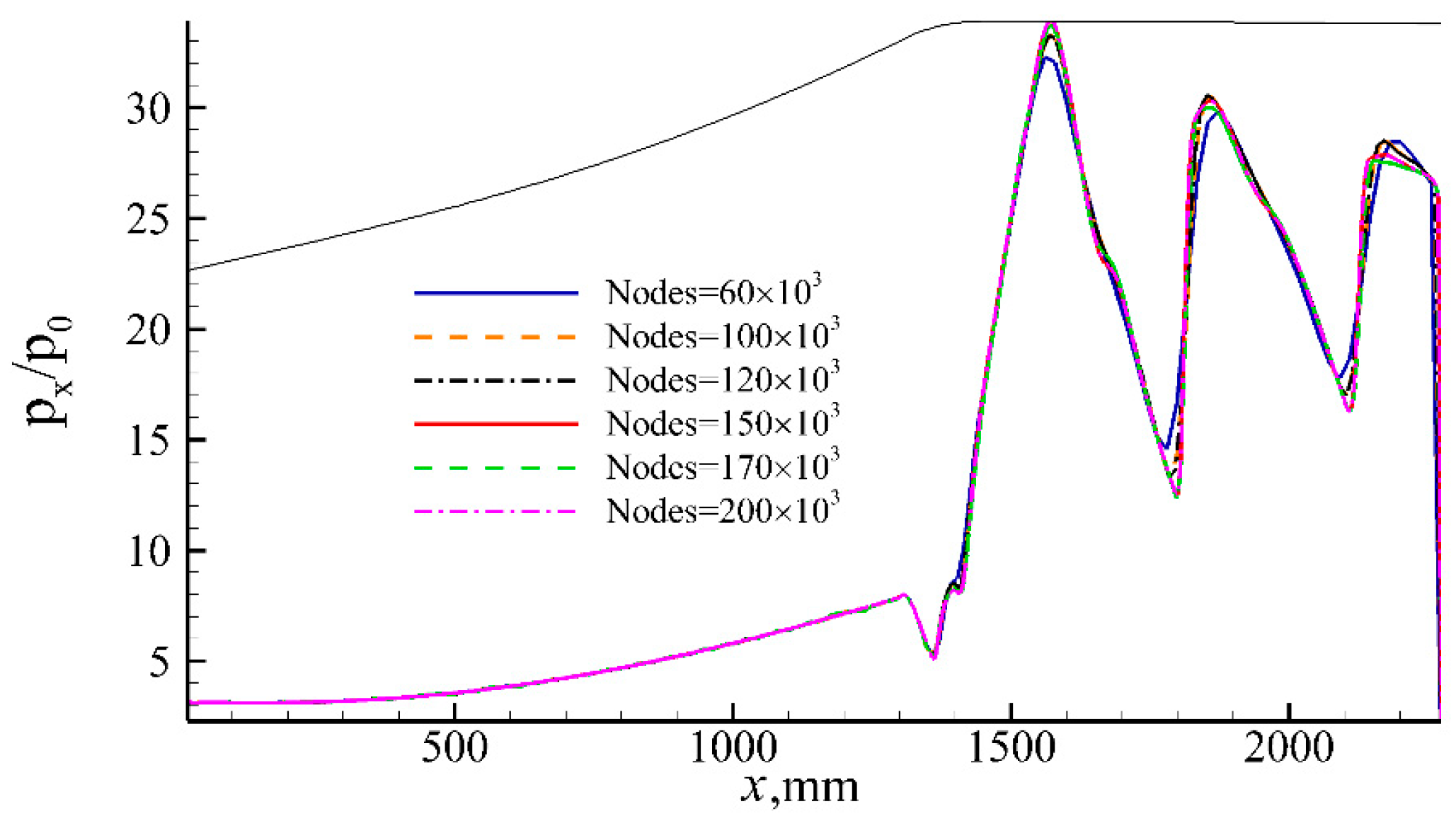
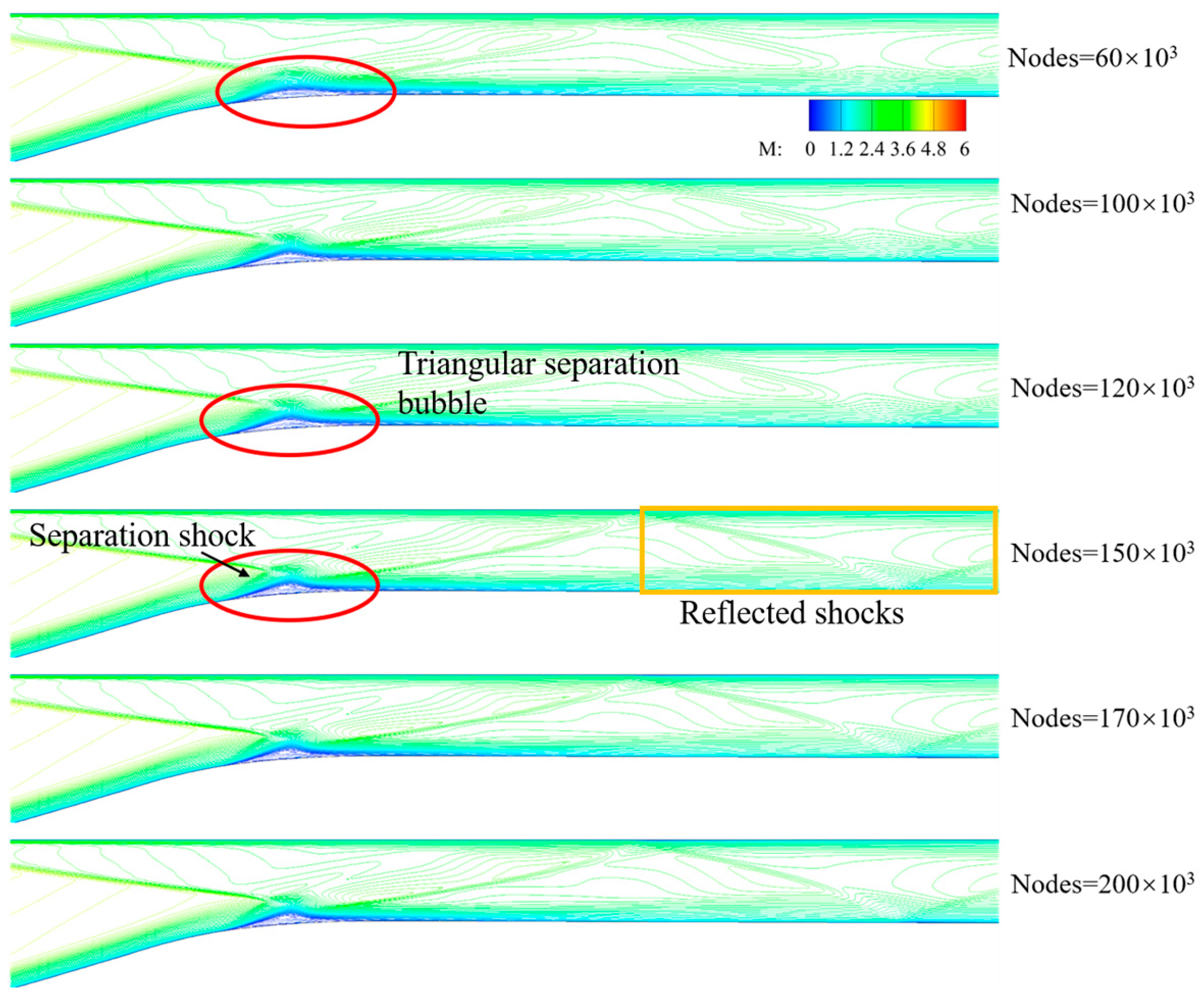
3.5. Validation of the Numerical Method and Grid Sensitivity
3.6. Numerical Dissipation Verification
4. Results and Discussion
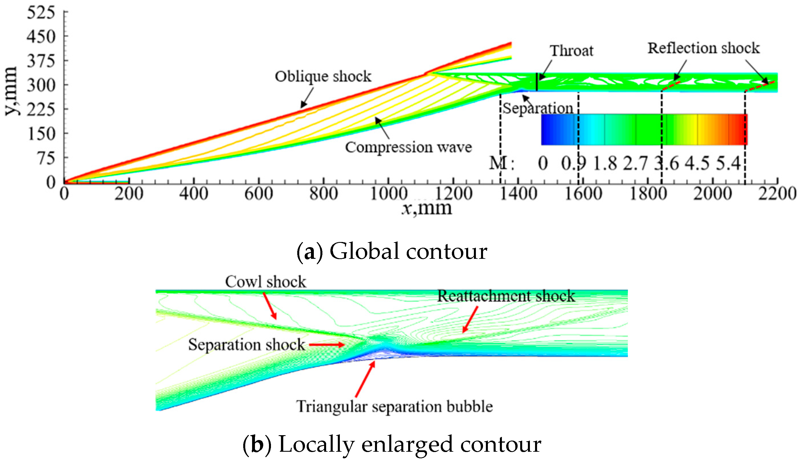
4.1. Effect of Wind Shear on Hypersonic Inlet/Isolator under Unthrottled Conditions
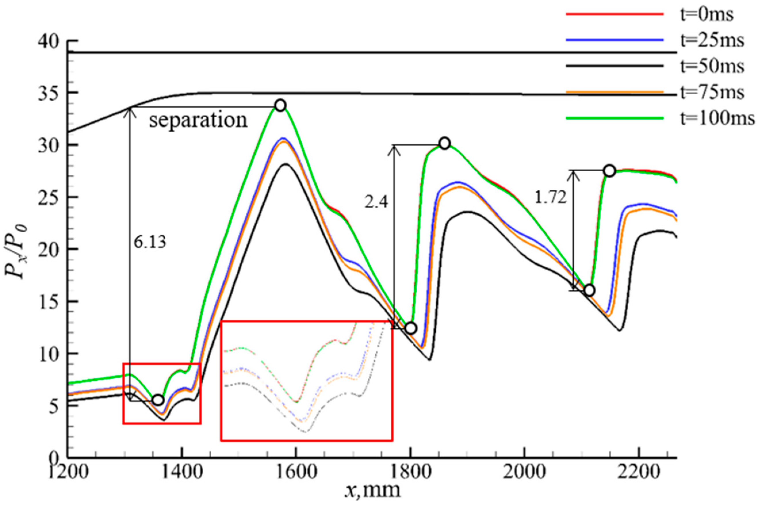
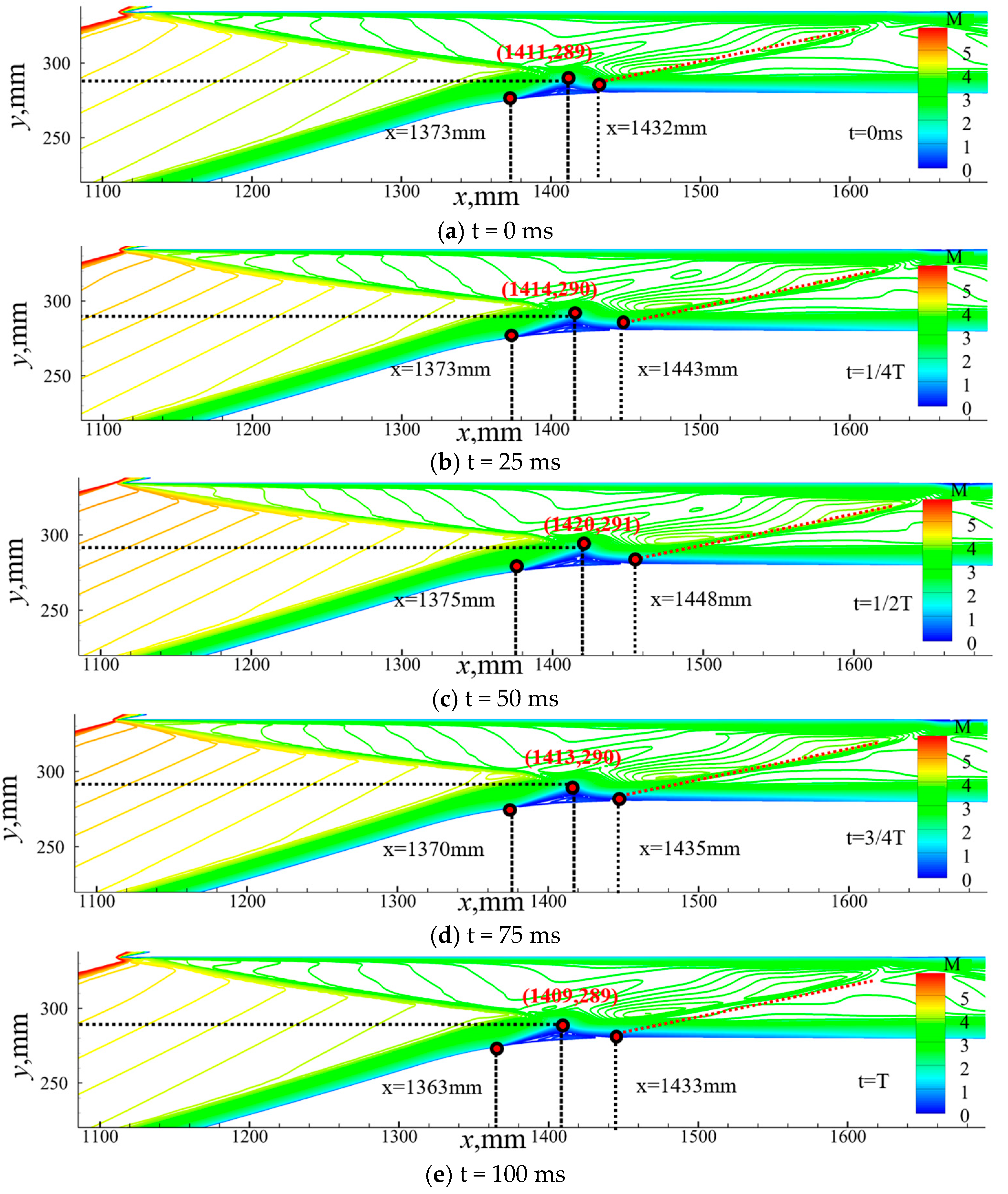
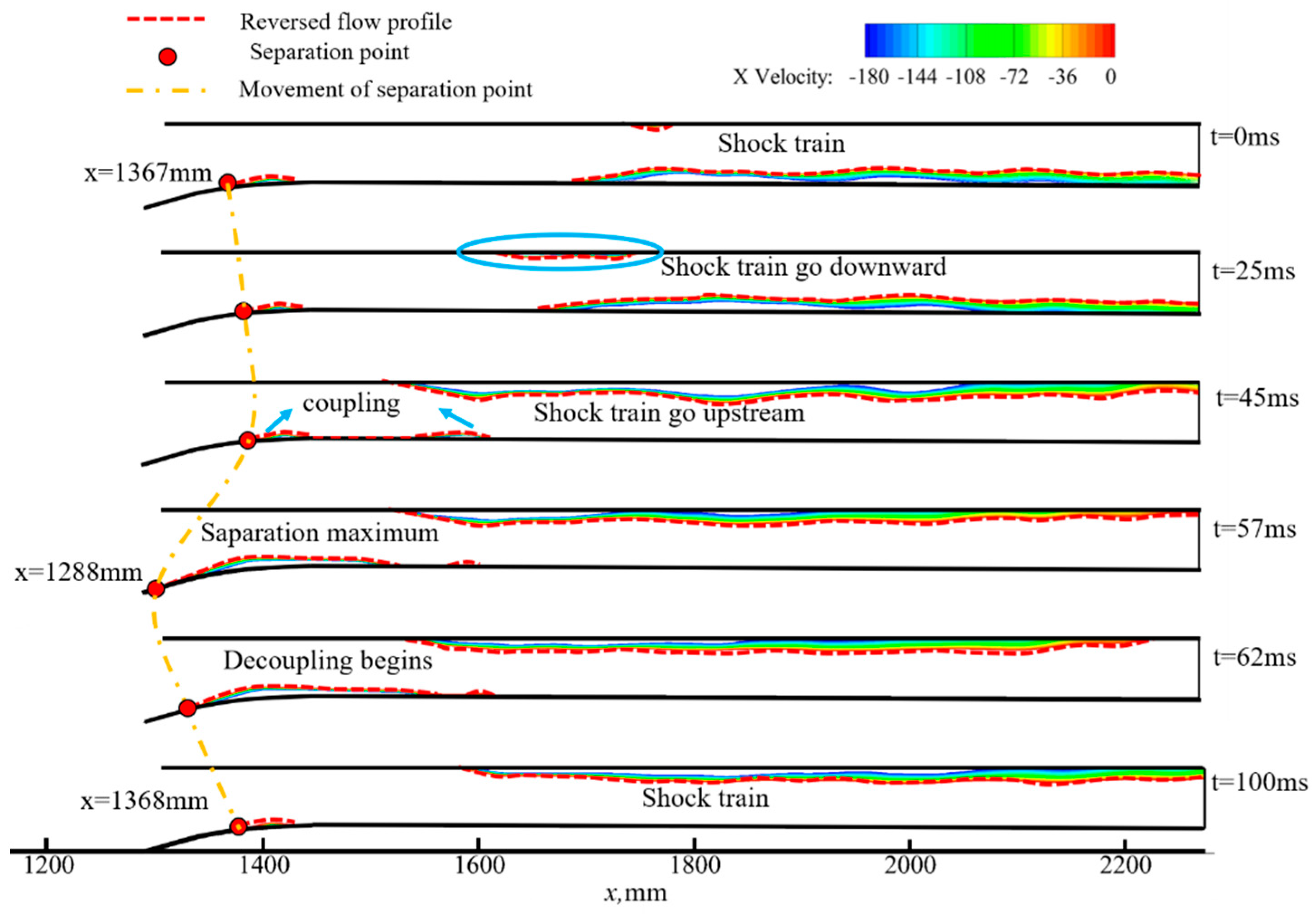
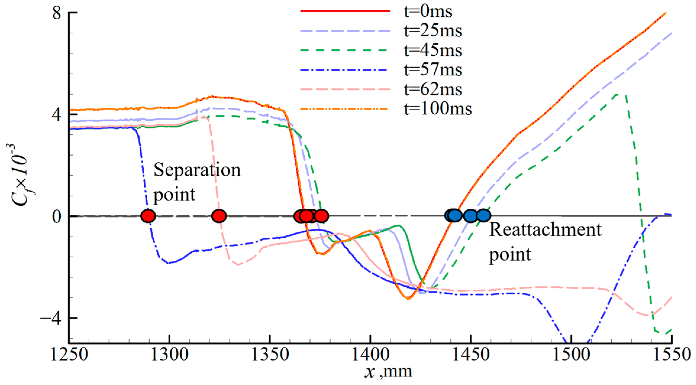
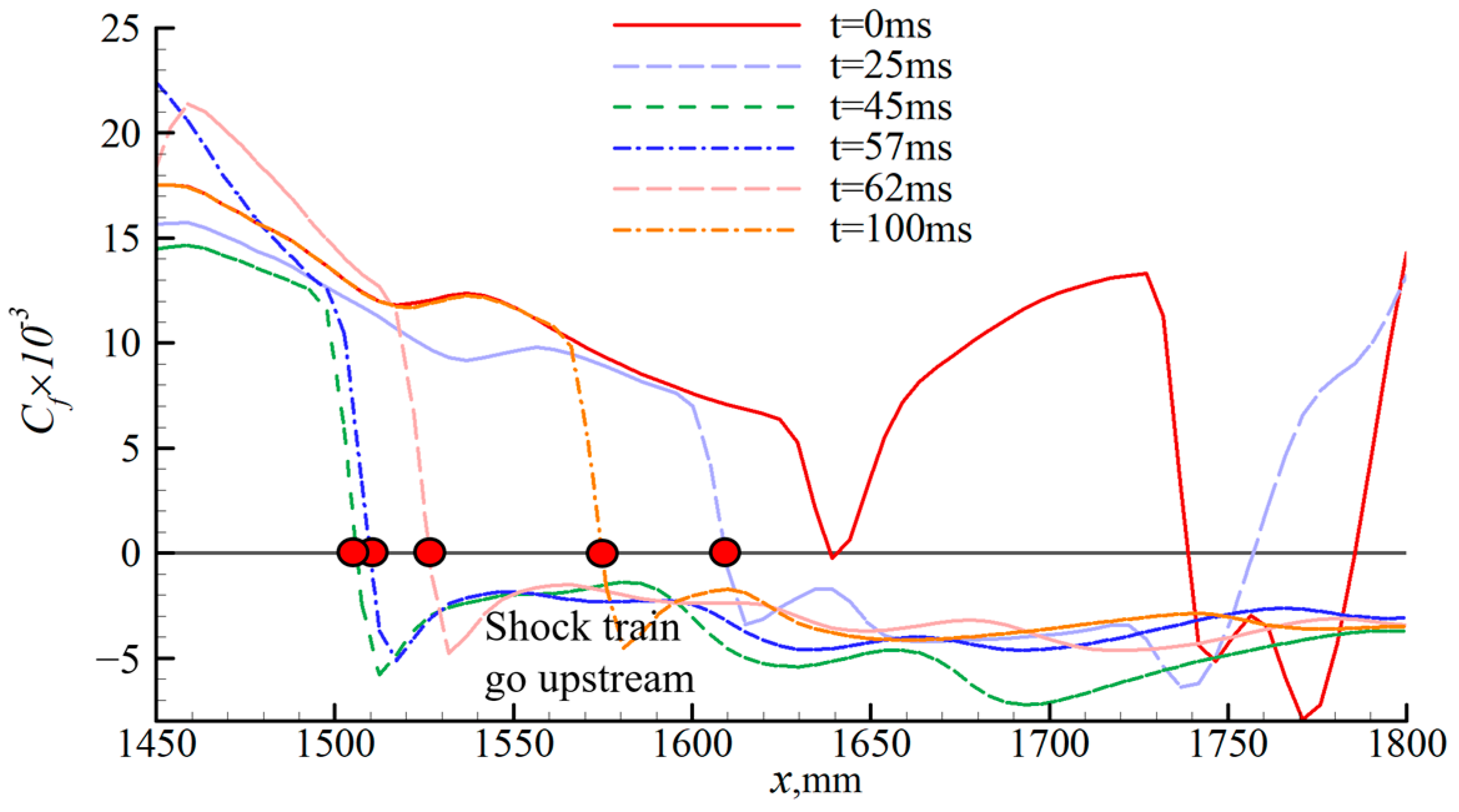
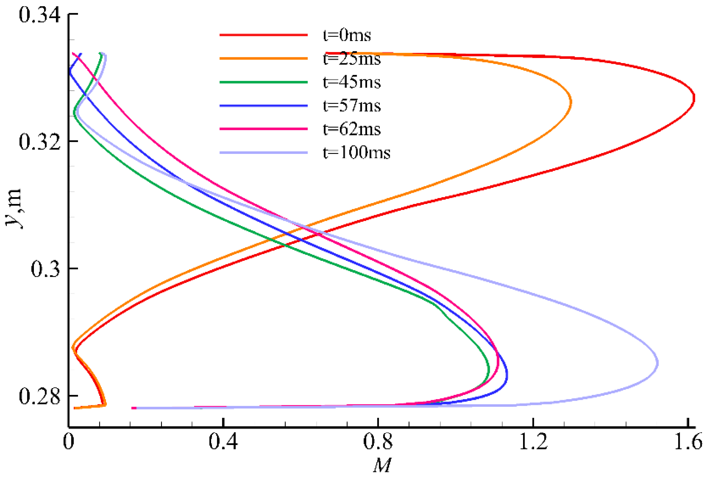
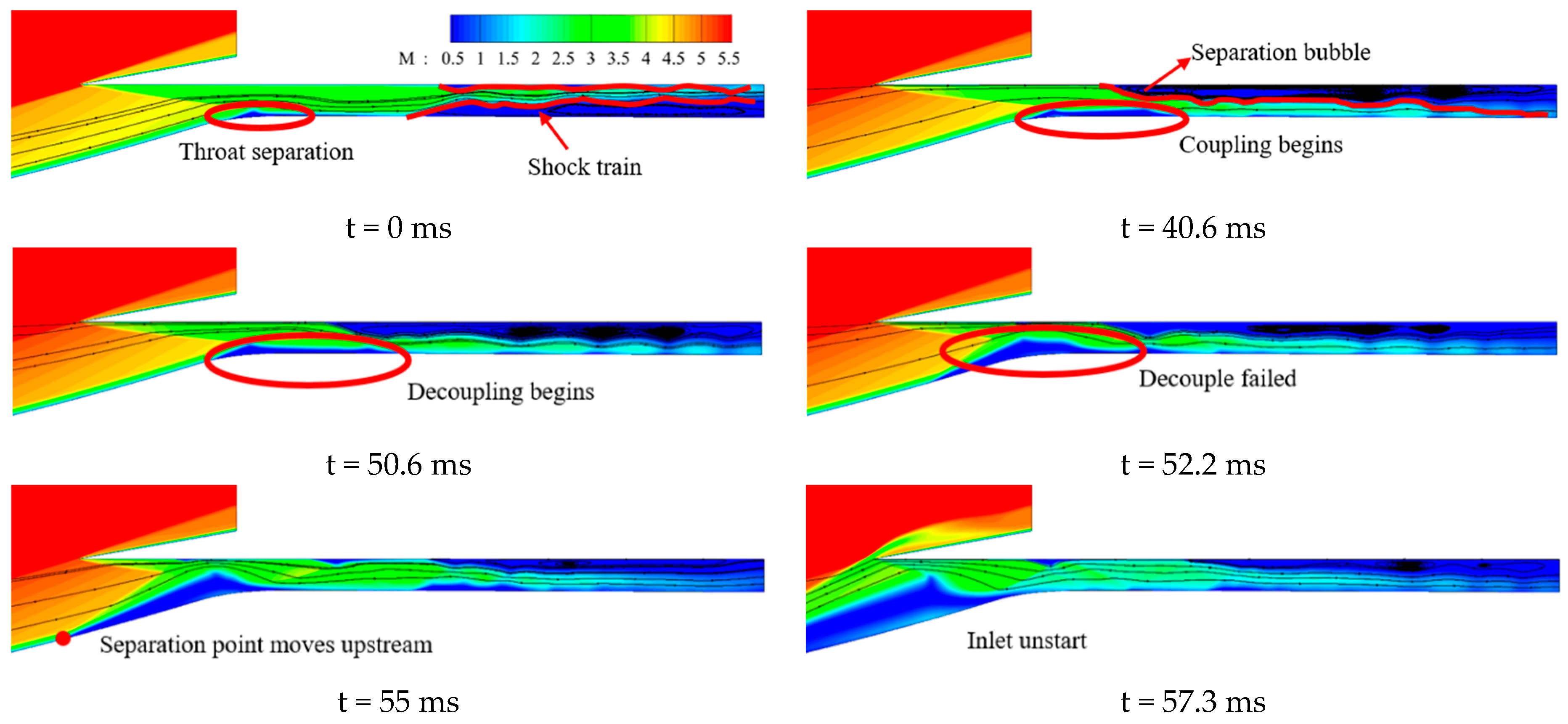
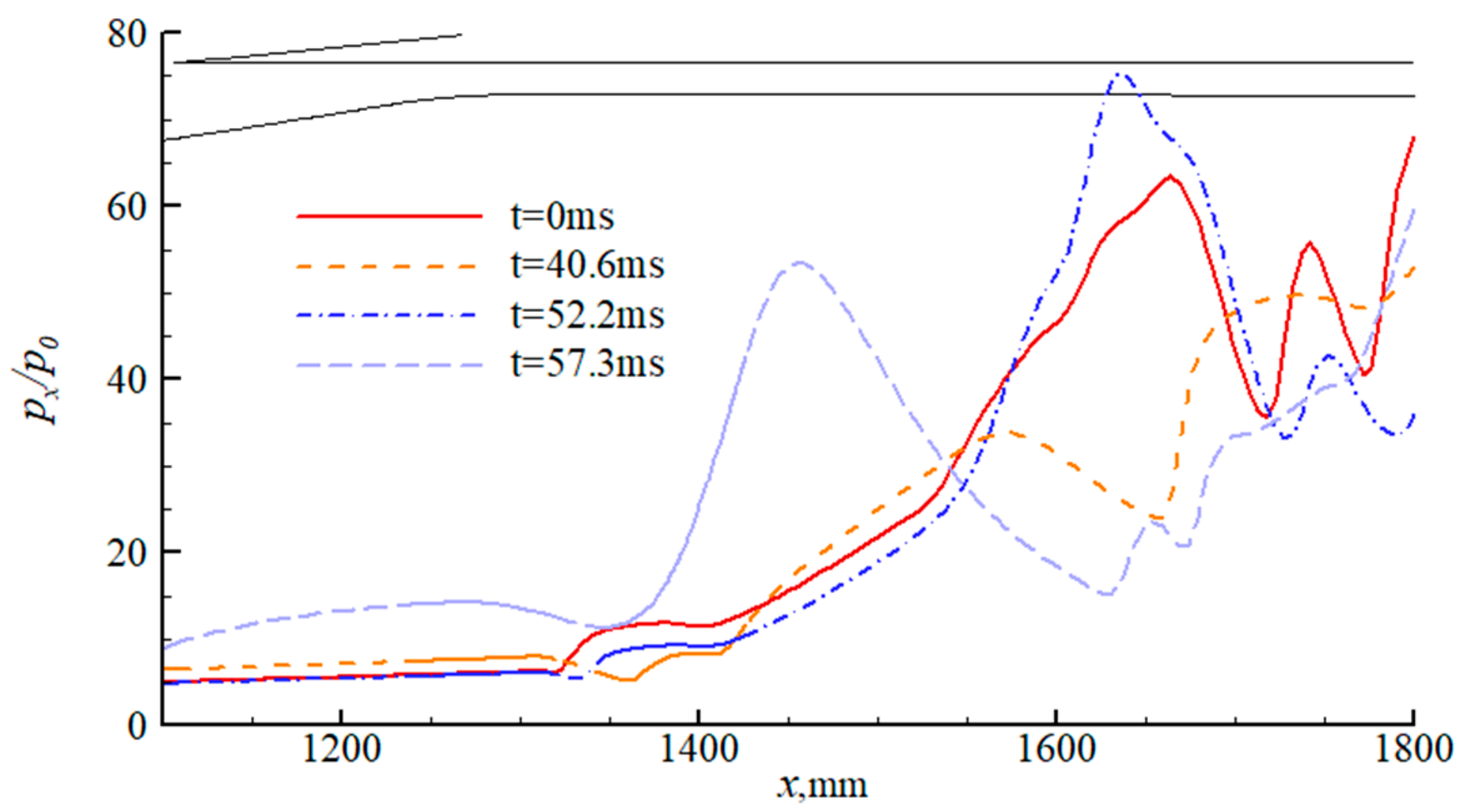
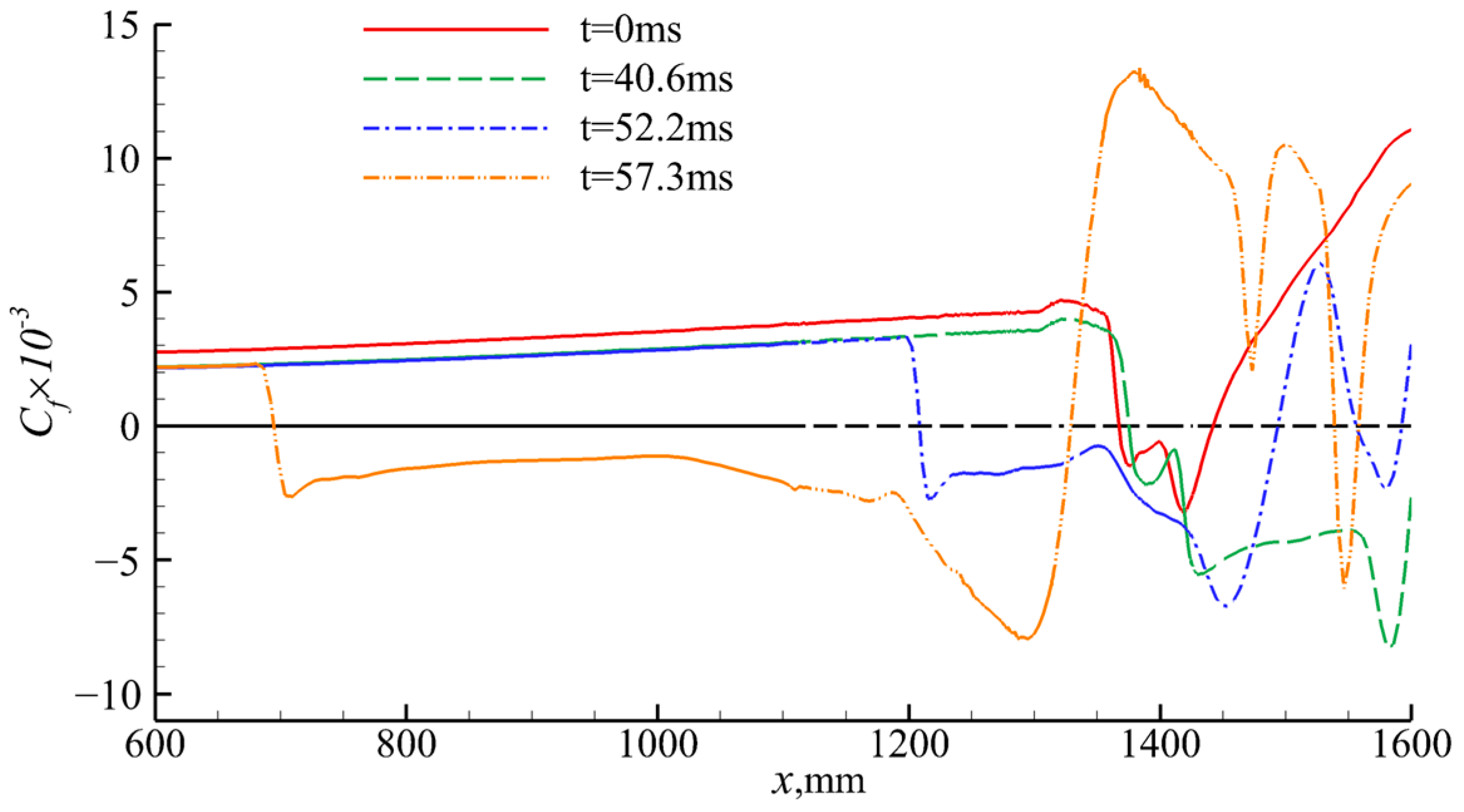
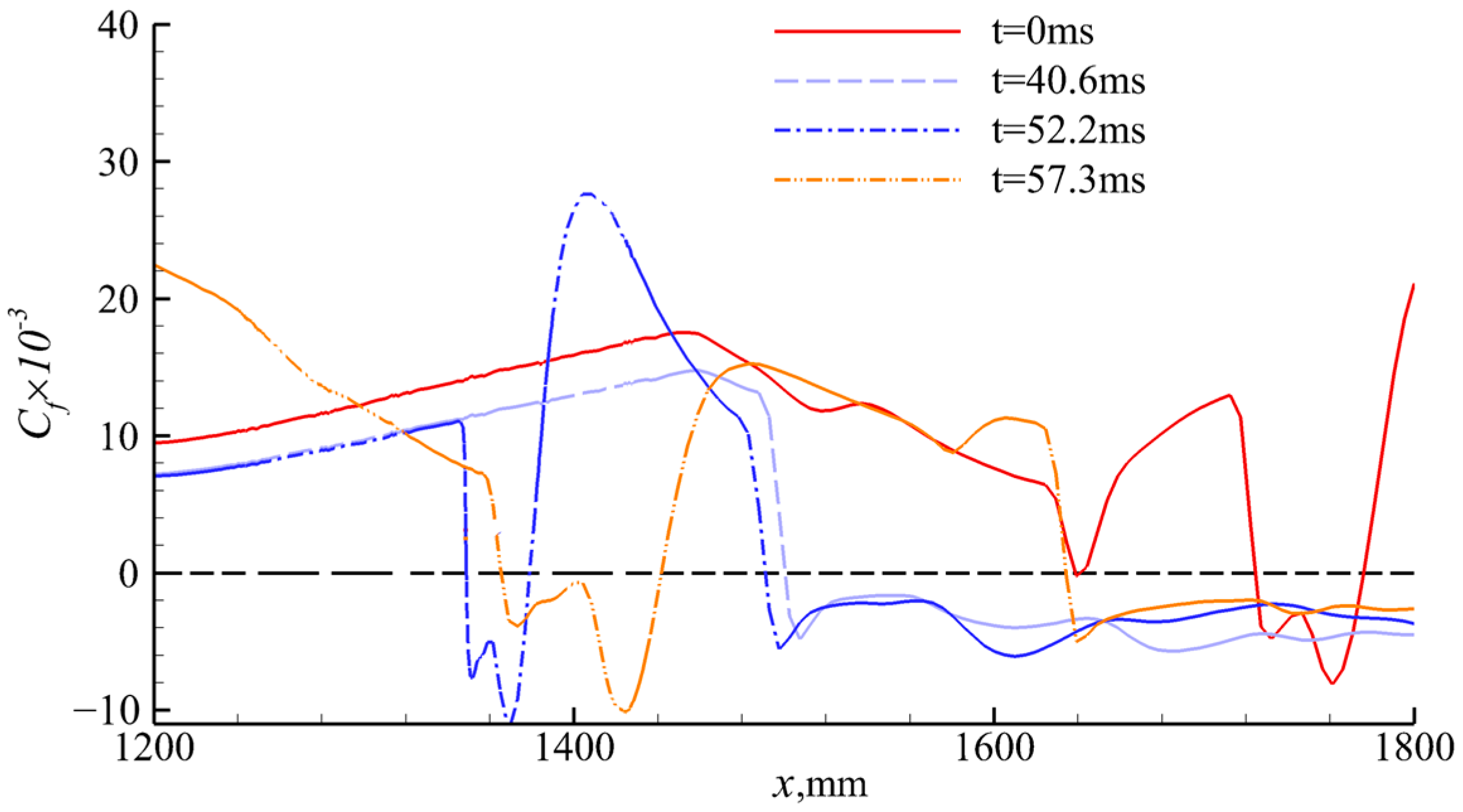
4.2. Effect of Wind Shear on Shock Train
5. Conclusions
Author Contributions
Funding
Data Availability Statement
Acknowledgments
Conflicts of Interest
References
- Van Wie, D.M.; D’Alessio, S.M.; White, M.E. Hypersonic Airbreathing Propulsion. Johns Hopkins APL Tech. Dig. 2005, 26, 430–437. [Google Scholar]
- Ferri, A. Review of scramjet propulsion technology. J. Aircraft. 1968, 5, 3–10. [Google Scholar] [CrossRef]
- McClinton, C.; Rausch, D.; Sitz, J.; Reukauf, P. Hyper-X program status. In Proceedings of the 10th AIAA/NAL-NASDA-ISAS International Space Planes and Hypersonic Systems and Technologies Conference, Kyoto, Japan, 24–27 April 2001. [Google Scholar]
- Moses, P. X-43C Plans and Status. In Proceedings of the 12th AIAA International Space Planes and Hypersonic Systems and Technologies, Norfolk, VA, USA, 15–19 December 2003. [Google Scholar]
- Huang, H.X.; Tan, H.J.; Li, F.B.; Tang, X.B.; Qin, Y.; Xie, L.B.; Xu, Y.Y.; Li, C.M.; Gao, S.M.; Zhang, Y.; et al. A review of the shock-dominated flow in a hypersonic inlet/isolator. Prog. Aerosp. Sci. 2023, 2023, 100952. [Google Scholar] [CrossRef]
- Rozario, D.; Zouaoui, Z. Computational Fluid Dynamic Analysis of Scramjet Inlet. In Proceedings of the 45th AIAA Aerospace Sciences Meeting and Exhibit, Reno NV, USA, 8–11 January 2007. [Google Scholar]
- Van Wie, D.; Kwok, F.; Walsh, R. Starting characteristics of supersonic inlets. In Proceedings of the 32nd Joint Propulsion Conference and Exhibit, Lake Buena Vista, FL, USA, 1–3 July 1996. [Google Scholar]
- Ma, R.P.; Liao, H.Z. The characteristics of winds at height of 20-80 km in the Chinese area. Chin. J. Space Sci. 1999, 19, 334–341. [Google Scholar] [CrossRef]
- Fleming, E.L.; Chandra, S.; Barnett, J.J.; Corney, M. Zonal mean temperature, pressure, zonal wind and geopotential height as functions of latitude. Adv. Space Res. 1990, 10, 11–59. [Google Scholar] [CrossRef]
- Fleming, E.L.; Chandra, S.; Burrage, M.D.; Skinner, W.R.; Hays, P.B.; Solheim, B.H.; Shepherd, G.G. Climatological mean wind observations from the UARS high-resolution Doppler imager and wind imaging interferometer: Comparison with current reference models. J. Geophys. Res. Atmos. 1996, 101, 10455–10473. [Google Scholar] [CrossRef]
- Johnson, D.; Roberts, B.; Vaughan, W.; Justus, C. Atmospheric Models For Engineering Applications. In Proceedings of the 41st Aerospace Sciences Meeting and Exhibit, Reno, NV, USA, 6–9 January 2003. [Google Scholar]
- Luers, J. A Model of Wind Shear and Turbulence in the Surface Boundary Layer; NASA: Washington, DC, USA, 1973. [Google Scholar]
- Smith, O.E. Vector Wind and Vector Wind Shear Models 0 to 27 km Altitude for Cape Kennedy, Florida, and Vandenberg AFB, California; NASA: Washington, DC, USA, 1976. [Google Scholar]
- Kozakiewicz, A.; Frant, M. Analysis of the gust impact on inlet vortex formation of the fuselage-shielded inlet of an jet engine powered aircraft. J. Theor. Appl. Mech. 2013, 51, 993–1002. [Google Scholar]
- Sun, S.; Wu, Z.; Huang, H.; Bangga, G.; Tan, H. Aerodynamic Response of a Serpentine Inlet to Horizontal Periodic Gusts. Aerospace 2022, 9, 824. [Google Scholar] [CrossRef]
- Halwas, H.K.; Aggarwal, S. Effect of Side Gust on Performance of External Compression Supersonic Inlet. J. Aircr. 2019, 56, 569–582. [Google Scholar] [CrossRef]
- Etkin, B. Effect of Wind Gradient on Glide and Climb. J. Aeronaut. Sci. 1947, 14, 365–367. [Google Scholar] [CrossRef]
- Etkin, B. Turbulent Wind and Its Effect on Flight. J. Aircr. 1981, 18, 327–345. [Google Scholar] [CrossRef]
- Etkin, B.; Hughes, P.C.; Zhu, S. Equivalent deterministic inputs for random processes. J. Guid. Control Dyn. 1984, 7, 477–482. [Google Scholar] [CrossRef]
- Xie, R.; Wang, X.M.; Gong, J.Y. Dynamic Modeling and Simulation for a Supermaneuverable Aircraft in Disturbance of Wind Field. In Proceedings of the 2012 Fifth International Conference on Intelligent Computation Technology and Automation, Zhangjiajie, China, 12–14 January 2012; pp. 147–150. [Google Scholar]
- Zhao, R.L.; Chen, Z.G.; Fu, W.X. Wind shear and rocket design. J. Astronaut. 1998, 19, 106–109. [Google Scholar]
- Yang, J.F.; Xiao, C.Y.; Hu, X.; Cheng, X. Wind shear characteristics in near space and their impacts on air vehicle. J. Beijing Univ. Aeronaut. Astronaut. 2019, 45, 57–65. [Google Scholar] [CrossRef]
- Woollen, J.; Sienkiewicz, M.; Ruddick, A.G.; Robertson, F.R.; Reichle, R.; Redder, C.R.; Pegion, P.; Pawson, S.; Owens, T.; Molod, A.; et al. MERRA: NASA’s Modern-Era Retrospective Analysis for Research and Applications. J. Clim. 2011, 24, 3624–3648. [Google Scholar] [CrossRef]
- Soltania, M.R.; Daliria, A.; Younsib, J.S. Effects of shock wave/boundary-layer interaction on performance and stability of a mixed-compression inlet. Sci. Iran. 2016, 23, 1811–1825. [Google Scholar] [CrossRef]
- Kianvashrad, N.; Knight, D. Large Eddy Simulation of Hypersonic Turbulent Boundary Layers. Fluids 2021, 6, 449. [Google Scholar] [CrossRef]
- Trapier, S.; Deck, S.; Duveau, P. Delayed Detached-Eddy Simulation of Supersonic Inlet Buzz. AIAA J. 2012, 46, 118–131. [Google Scholar] [CrossRef]
- Zhong, X.L.; Wang, X.W. Direct Numerical Simulation on the Receptivity, Instability, and Transition of Hypersonic Boundary Layers. Annu. Rev. 2012, 44, 527–561. [Google Scholar] [CrossRef]
- Menter, F.R. Two-equation eddy-viscosity turbulence models for engineering applications. AIAA J. 1994, 32, 1598–1605. [Google Scholar] [CrossRef]
- Simeonides, G.; Haase, W.; Manna, M. Experimental, analytical, and computational methods applied to hypersonic compression ramp flows. AIAA J. 1994, 32, 301–310. [Google Scholar] [CrossRef]
- Mansour, A.; Laurien, E. Numerical error analysis for three-dimensional CFD simulations in the tworoom model containment THAI+: Grid convergence index, wall treatment error and scalability tests. Nucl. Eng. Des. 2018, 326, 220–233. [Google Scholar] [CrossRef]
- Zhang, Y.; Tan, H.J.; Zhuang, Y.; Wang, D.P. Influence of Expansion Waves on Cowl Shock/Boundary Layer Inte8action in Hypersonic Inlets. J. Propuls. Power 2014, 30, 1183–1191. [Google Scholar] [CrossRef]
- Huang, H.X.; Sun, S.; Tan, H.j.; Ning, L.; Wang, J. Characterization of Two Typical Unthrottled Flows in Hypersonic Inlet/Isolator Models. J. Aircr. 2015, 52, 1715–1721. [Google Scholar] [CrossRef]
- Huang, H.X.; Tan, H.J.; Zhuang, Y.; Sheng, F.J.; Sun, S. Progress in Internal Flow Characteristics of Hypersonic Inlet/Isolator. J. Propuls. Technol. 2018, 39, 2252–2273. [Google Scholar] [CrossRef]
- Huang, H.X.; Tan, H.J.; Sun, S.; Wang, Z.Y. Behavior of Shock Train in Curved Isolators with Complex Background Waves. AIAA J. 2018, 56, 329–341. [Google Scholar] [CrossRef]
- Tan, H.J.; Sun, S.; Huang, H.X. Behavior of shock trains in a hypersonic inlet/isolator model with complex background waves. Exp. Fluids 2012, 53, 1647–1661. [Google Scholar] [CrossRef]
- Huang, H.X.; Tan, H.J.; Sun, S.; Sheng, F.J. Unthrottled Flows with Complex Background Waves in Curved Isolators. AIAA J. 2017, 55, 2942–2955. [Google Scholar] [CrossRef]


| Parameters | Value |
|---|---|
| 17.13 | |
| 8.73 | |
| Hth, mm | 53 |
| Parameter | Value |
|---|---|
| On-design freestream Mach number | 6.0 |
| Air model | Ideal gas |
| Altitude, km | 30 |
| Presser, Pa | 1197.003 |
| Temperature, K | 226.509 |
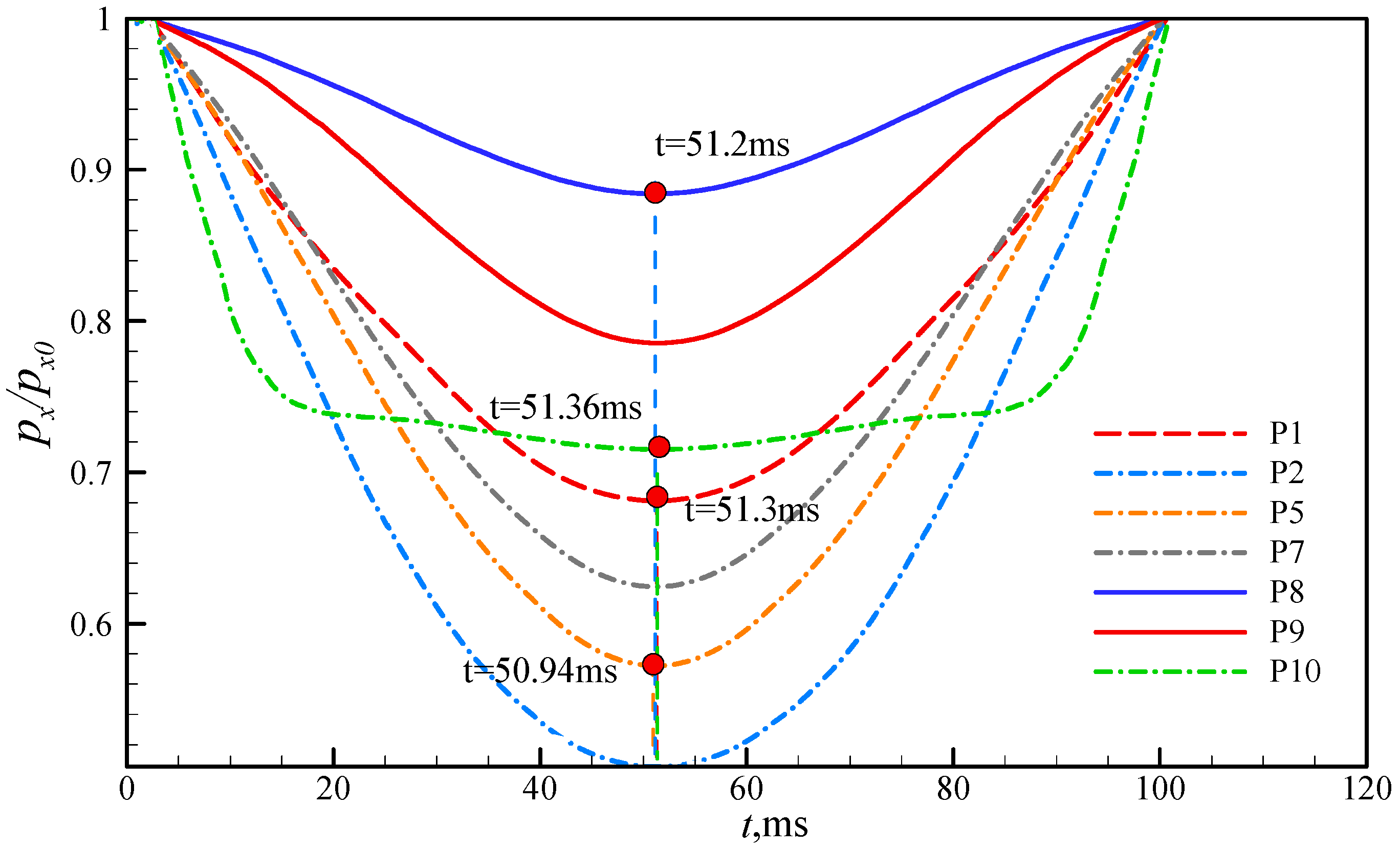
| Point | P1 | P2 | P3 | P4 | P5 | P6 | P7 | P8 | P9 | P10 |
|---|---|---|---|---|---|---|---|---|---|---|
| x, mm | 1411 | 1425 | 1433 | 1440 | 1444 | 1446 | 1455 | 1625 | 1792 | 2065 |
| y, mm | 281 | 281 | 282 | 282 | 282 | 282 | 282 | 283 | 283 | 283 |
Disclaimer/Publisher’s Note: The statements, opinions and data contained in all publications are solely those of the individual author(s) and contributor(s) and not of MDPI and/or the editor(s). MDPI and/or the editor(s) disclaim responsibility for any injury to people or property resulting from any ideas, methods, instructions or products referred to in the content. |
© 2023 by the authors. Licensee MDPI, Basel, Switzerland. This article is an open access article distributed under the terms and conditions of the Creative Commons Attribution (CC BY) license (https://creativecommons.org/licenses/by/4.0/).
Share and Cite
Gao, S.; Huang, H.; Meng, Y.; Tan, H.; Liu, M.; Guo, K. Transient Flow Evolution of a Hypersonic Inlet/Isolator with Incoming Windshear. Aerospace 2023, 10, 1021. https://doi.org/10.3390/aerospace10121021
Gao S, Huang H, Meng Y, Tan H, Liu M, Guo K. Transient Flow Evolution of a Hypersonic Inlet/Isolator with Incoming Windshear. Aerospace. 2023; 10(12):1021. https://doi.org/10.3390/aerospace10121021
Chicago/Turabian StyleGao, Simin, Hexia Huang, Yupeng Meng, Huijun Tan, Mengying Liu, and Kun Guo. 2023. "Transient Flow Evolution of a Hypersonic Inlet/Isolator with Incoming Windshear" Aerospace 10, no. 12: 1021. https://doi.org/10.3390/aerospace10121021
APA StyleGao, S., Huang, H., Meng, Y., Tan, H., Liu, M., & Guo, K. (2023). Transient Flow Evolution of a Hypersonic Inlet/Isolator with Incoming Windshear. Aerospace, 10(12), 1021. https://doi.org/10.3390/aerospace10121021