Abstract
A new Range Equation for a hybrid-electric propeller-driven aircraft was formulated by an original derivation based on the comparison of Virtual Electrical Aircraft (VEA) and Virtual Thermal Aircraft (VTA) range equations. The new formulation makes it possible to study the range of a hybrid aircraft with pre-established values of electric motor usage rate. The fuel and battery mass are defined “a priori”, and do not depend on the power split, so even the aircraft’s total mass is constant. The comparison with the typical range formulas available for hybrid aircraft was made on the basis of a reference composite VLA category aircraft manufactured by the CFM Air company. The analysis carried out shows that there is an optimum hybridization level as a function of the pre-set specific energy of the batteries system.
1. Introduction
Electric-powered vehicles (in general) have many advantages compared to those based on internal combustion engine (ICE). First, of all, the possibility of covering energy demands with clean renewable energy. In terms of aeronautics, a more-electric aircraft could potentially be more reliable, as the mechanical systems are replaced by electric ones. Higher reliability also implies lower maintenance costs, and only a slight reduction in engine performance due to altitude. Furthermore, electric motor offers a power density rate up to six times the density of a conventional ICE. Electrification may also enable concepts of operations that are not currently served with conventional architectures such as electric vertical takeoff and landing (e-VTOL) concepts [1] An interesting survey of scholarly and business literature on fixed-wing aircraft propelled in whole or in part by electricity is reported in [2]. This includes all-electric, hybrid electric, and turbo-electric architectures. The weight of the conventional electric energy systems is the greatest issue concerning the electrical transition in aeronautics [3]. Due to the expected high energy density and the short duration of refueling, PEMFC hydrogen systems are a very promising technology to extend electrical aircraft endurance and optimize reliability without noise increase. PEMFC fuel cell systems have already been integrated within aircraft not only for Auxiliary Power Unit (APU) applications, but also as the main power source dedicated to propulsion. Within the ENFICA-FC project coordinated by POLITO, an All-Electrically-powered two-seater Aeroplane (FAI Sporting Code Category C airplane) was successfully tested in 2010 [4,5,6]. ZeroAvia, a British/American hydrogen-electric aircraft developer, already demonstrated flights up to 800 km in aircraft of up to 20 seats. According to the company, by 2026, ZeroAvia intends to fly an aircraft, 80 seats, over a 800 km range. Conventional off-the-shelf batteries (mainly Lithium-Ion batteries) have lower energy density compared to FC-Systems, although new batteries are under development such as solid state batteries. Battery-only propulsion is not a viable option to reduce the environmental impact of the aeronautical sector unless the mission range is drastically reduced. Hybrids combine different technologies to provide the power required by the aircraft. The leading hybrid combinations available are internal combustion engine and batteries, gas turbine and batteries, fuel cell and batteries. Hybrids increase the specific energy of the power source because liquid propellants can store more energy than batteries in the same amount of weight. Internal combustion engine and battery hybrid are common in the automotive industry. The internal combustion engine and the electric motor can be connected in two ways [2]. In the parallel hybrid, the internal combustion engine and the electric motor are connected to the same shaft and the torques provided by the two systems add. This is the configuration that has the lowest possible requirements on the electric motor and batteries. In the series hybrid, the internal combustion engine is directly connected to a generator that provides power to the battery. In conventional aircraft, both architectures can be employed because, like in a car, there is only one power shaft. Distributed propulsion concepts make the parallel hybrid configuration impossible [7]. An example of parallel architecture is the one developed by C.F.M. Air within the EU-Blu Spark project where a modular parallel hybrid power unit is proposed [8]. Another example of a conventional aircraft powered by a hybrid powertrain is the Diamond DA36 E-Star [9], which is powered by a Siemens 70 kW electric motor from power generated by a 30 kW Austro Engines Wankel rotary engine and generator. This was the first aircraft with a serial hybrid electric drive system and it can take off on electric power only. In order to compare different electric hybrid solutions, some simplified sizing methods are required during the preliminary feasibility study phase [10,11,12,13,14]. Any range equation based on the “energy approach” implies that the airplane’s mass depends on the energy split ratio. Let us take the example of the formulas provided by De Vries et al. in [15]. As the authors claim the proposed equation (Equation (17) in [15]) should be used to calculate the necessary energy to achieve a required range depending on the power split. In [16], the battery and the fuel weights are constrained to the power split and for this reason: if the power split increases, then the fuel mass decreases, and the battery mass increases. In an actual application, the lower energy density of the batteries drives their weight to grow faster, causing the overall weight to rise. Switching from weights to weight fractions is an everyday necessity, but this is quite complicated in energy-based formulas where the weight fractions depend on the power split. For this reason, the authors of [15] use the Operative Empty weight and the Payload weight expressed in Newtons. The same goes for Roachs et al. in [16]. The recent approach described in [17] include a new efficiency-based definition of the degree of hybridization, including the efficiencies of the electric or fuel-powered drivetrain, but still present limitations of the previous energy-based approaches. An energy-based approach can be used only in airplane design, but when it comes to evaluating the performance of an existing aircraft with a different power split than the design value, it fails. This paper aims to overcome the limitations found in the literature and provide a new range equation such that:
- The power split is a third variable unlaced from the fuel and the battery mass, so that it is possible to choose a power management strategy and have a multiple-segments cruise, each with its power split;
- The equation can use weight fractions, which do not depend on the power split. Thus, the fuel and battery mass are defined a priori and do not depend on the power split, so even the aircraft’s total mass is constant;
- The equation uses the state of charge and the fuel mass instead of the energy level;
- The power split must be defined at the mechanical power level rather than at the energy source level. The reason is that the first value can be easily measured and used in the control system logic.
The energy-based approach always provides a condition of optimal weight utilization: the aircraft uses up energy and fuel simultaneously, and it is a direct consequence of how the weight of the two sources is defined. Instead, the following approach opens up for non-optimal weight utilization conditions, but it allows for easy monitoring of the airplane’s performance as the power split changes. The work is arranged as follows. The analytical model is derived in Section 2. The reference aircraft is presented in Section 3. Results from previous range equations and comparison with the present equation are proposed in Section 4. Section 5 introduces the validation of the present formulation with a dynamic model followed by conclusions in Section 6.
2. Analytical Model
Consider a hybrid aircraft with definite maximum take-off mass and initial mass ratios. The total mass is composed as follows:
where is the mass of the structures, is the battery mass, is the payload mass, the fuel mass and is the electrical equipment mass (motor, inverter, BMS, cables, etc.). The takeoff mass can be split into a fixed part (the empty operative mass plus the payload mass plus the battery pack mass and a variable part, the fuel mass .
The aircraft has a hybrid propulsion system with parallel or series architecture as shown in Figure 1 and Figure 2 respectively.

Figure 1.
Parallel hybrid architecture.

Figure 2.
Serial hybrid architecture.
As performed in [12,15], a generalized formulation for both configurations can be achieved merely by defining overall efficiencies, as shown in Table 1. It is possible to define a generic representation in which we have two branches representing the two sources of energy (fuel and batteries) called branch 1 and 2, respectively, and the dissipating branch indicated with 3 as shown in Figure 3. Assume that the aircraft travels a straight trajectory at a constant altitude. Assume that the power required by drag is instantaneously equal to the available propulsive power .

Table 1.
Overall efficiencies.
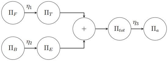
Figure 3.
Generalized diagram.
The available power equals the total power multiplied by the overall efficiency . Inversely,
The hybridization level defines the total power fraction the electric part must supply on total shaft power. The conventional engine part provides the remaining fraction.
If the parallel architecture is used, the total power is equal to the mechanical shaft power. Else, in the case of series configuration, the total power is equal to the electric motor input power.
The fuel must provide a chemical power that is equal to
where . On the other hand, the battery must provide a discharge power that is
2.1. The “Virtual Aircraft” Method
Imagine the hybrid aircraft as a composition of two “virtual” aircraft: a purely thermal aircraft and a purely electric aircraft. The “virtual electric” aircraft requires an amount of power equal to in order to fly at the required speed. The “virtual thermal” aircraft requires . These aircraft can virtually fly until they run out of fuel or charge. Since exhaustion is not simultaneous, each airplane can travel a different distance independently. Let the range of the first aircraft be the “virtual electric aircraft range” . Let the range of the second be the “virtual thermal aircraft range” . Based on the hypothesis made for the analysis performed in this paper, the minimum of these two values is the hybrid aircraft range, because having fixed the level of hybridization , the maximum range is determined by the energy source that runs out first.
2.1.1. Virtual Thermal Aircraft (VTA)
The VTA range analytical expression can be obtained by retracing the demonstration of the conventional Breguet range equation, including the factor , in order to take into account the power split.
It is obtained by integrating the differential equation governing the variation in fuel weight (or total weight). The VTA consumes a weight of fuel that depends on the required power of the thermal engine and thermodynamic efficiency.
The total weight is split into a fixed part and a variable part as discussed in (2). The differential equation is solved using the technique of variables separation.
Since , the t variable is replaced with R
The coefficient of the differential is assumed as a constant, and it is replaced with:
The previous integral has a closed-form solution:
If the generic range coincides with the maximum range that can be covered by the VTA, then the equation is rewritten as
Finally, an expression of the VTA range as a function of the weight of fuel consumed, the efficiency and the parameter is obtained.
The equation can be further developed by introducing mass instead of weight:
2.1.2. Virtual Electrical Aircraft (VEA)
The virtual electric aircraft, while utilizing only battery power, benefits from the weight of fuel consumed by its virtual thermal counterpart. For all intents and purposes, it is an electric aircraft with a weight that decreases over time. However, its range is related only to the consumption of electrical energy. At the initial instant, the battery contains a certain amount of energy. The change in energy over time is equal to the required power of the battery pack.
Separating the variables and replacing the time variable with the variable range gives the following expression:
At this point, it is necessary to determine a relationship between the weight of fuel consumed and the distance traveled . This relationship was obtained at (13), which, suitably inverted, allows to find a direct relationship between the total weight and the range.
Before proceeding with the integration, the coefficient preceding the differential is renamed.
Integrating from the initial instant to the final instant:
The closed expression of the previous integral is:
The inverted expression leads us to write:
Again substituting the auxiliary parameters and , it is possible to arrive at a definitive expression of the range of the virtual electric aircraft.
Sometimes, it is more convenient to use mass rather than weight.
Equations (16) and (27) can be rewritten using the fractions of weight, particularly useful in the conceptual design phases, when the maximum take-off weight of the aircraft is not yet known.
The fixed weight fraction is defined as the ratio of the fixed mass to the take-off mass. It can be expressed in terms of the other fractions.
Let be the energy density of the battery pack. The stored energy can be written as:
Given that part of the energy can be consumed in the preceding and following flight phases, it is useful to redefine the energy as a function of the state of charge of the battery, assuming that it works on a constant voltage range. Collecting the quantity in numerator and denominator:
is the minimum acceptable state of charge at the end of the cruise. It does not mean that the battery will be discharged to , it is just a lower limit. In fact, a certain amount of charge may be necessary for completing other flight phases.
Finally, the two definitive expressions of the ranges of the virtual aircraft are obtained:
where is the lowest acceptable amount of fuel at the end of the cruise. Again, not all the predicted fuel must be burnt, is the lowest limit.
Equation (32) can be derived from (33) calculating the amount of fuel at the end of the segment depending on the amount of battery energy used. Use this alternative procedure:
Integrating in the range :
The left member of the equation is the theoretically usable fuel energy, the right is the theoretically usable battery energy. The equation constrains the energy consumption so that the lower value limits the higher. For example, if the theoretically usable fuel energy is more than the theoretically usable battery energy, then the battery energy becomes the actual usable battery energy and limits the amount of fuel energy, indicated by , where L stands for “limited”.
Obviously, the equation can be reversed if the theoretically usable fuel energy is less than the theoretically usable battery energy. For now, let us assume the first possibility, so the fuel is limited by the charge. Switch to mass fraction and divide by :
2.1.3. Overall Range
The range of the real hybrid aircraft is given, for a certain value , by the minimum between the VTA range and the VEA range.
The solution of the maximum range can be determined numerically by imposing .
3. Reference Aircraft
As a test case airplane, the Dardo aircraft made by C.F.M. Air (a company based in Cirié (TO), Italy, who are active in the design and manufacturing of General Aviation airplanes) has been considered. Its most promising project is the Dardo, a single-engine propeller aircraft capable of carrying two passengers for about 1200 km at a speed of 250 km/h. The aircraft is undergoing certification. The aircraft is a low-wing with a positive dihedral angle, designed to have high efficiency and great maneuverability even at high speeds. The aircraft, with the engine in thermal configuration only, is a variable pitch propeller configuration powered by the 115 hp Rotax 914 UL with boost at take-off (84.5 kW for a maximum of 5 min, 73.5 kW in continuous operation). The motor weighs 78 kg and has a specific power of 0.94 kW/kg calculated on the continuously power delivered (1.08 kW/kg to the maximum power).
The hybrid version (Figure 4) will be developed starting from the one described above, minimizing changes and limiting them where strictly necessary. The most important and influential aspect of the hybrid Dardo project is the requirement to achieve the safety level of a twin engine: both engines (electric and piston) must be able to perform the airplane take off following standard of the CS-23. In this way, the chances of a severe accident following a piston engine failure during take off would be very low and the risk for passengers would be minimal. The same goes for reversing the electric motor with piston engine. The safety-oriented design philosophy leads to an engine design less performing than others: the best design combination, from the point of view of weight and range, would be to have an electric engine adequate to perform the takeoff and use a smaller piston engine for cruising. Moreover, the aircraft is able to complete takeoff in case of one engine (thermal or electric) loss. The battery pack would have minimum dimensions and would contain only the energy necessary to transfer the aircraft at cruising altitude reducing its weight. This strategy would be well suited to the new design of a hybrid aircraft, but does not introduce advantages either from the point of view of safety or from the point of view of CO2 emissions, as can be seen in the Section 4. The safety-oriented design philosophy, on the other hand, allows us to reach lower performances, but with a level of safety equal to that of a twin engine. Hybrid airplane mass fractions and reference parameters are reported in Table 2.

Figure 4.
Dardo hybrid with parallel motor configuration detail.

Table 2.
Hybrid airplane mass fractions and reference parameters used in the confrontation of the analytical equations found in the bibliography.
4. Results
Considering the typical parameters of the hybrid Dardo configuration indicated in Table 2, Equations (32) and (33) or the envelop expressed in (40) are compared with formulas proposed by the literature and, in particular, with formulas proposed by Reynard De Vries and Maurice Hoogreef in [15] and recently modified in [17].
4.1. Range Equation from the Literature [15,17]
Our concerns here are on how much residual fuel there is at the end. If the airplane runs out of fuel before running out of battery energy, the cruise is no more with a constant power split. The same happens if the battery energy runs out before fuel. In some cases, not all of the battery energy can be used, and in other situations, not all of the fuel can be burnt. After the definition of an aircraft’s initial mass and weight fractions, an appropriate value of and is set and a fixed power split is considered. There are three possibilities:
- The power split is constant, and the cruise ends when one of the energy sources does;
- The aircraft consumes all the energy sources, and, if one runs out before the other, the power split cannot be constant for all the cruise. (i.e., if the batteries are below then the must go to 0);
- The energy sources run out exactly at the same time.
Three forms of the formula proposed by authors have been considered.
Firstly, Equation (15) in [15] has been considered in its original form, but with a mass fraction. The fuel at the end of the cruise is imposed as a fraction of twenty percent of the initial fuel.
Let us divide by :
A fixed value of independent from the battery state of charge has been selected. The graph in Figure 5 shows that if the power split is increased then the range of the airplane goes to infinity, but this is inconsistent: if the amount of electric energy stored is known in advance, there is no way the range could increase using more electric power. This means that cannot assume any value. Hence, another definition of depending on the battery and must be formulated.
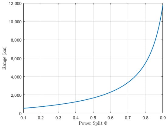
Figure 5.
Range using original Equation (15) of [15].
Equation (15) in [15] has been considered in an adapted form linked to the battery state of charge. The fuel at the end of the cruise is calculated based on how much battery energy is consumed. As the authors claim, if the power split is constant, the fuel energy used can be related to the battery energy consumed:
Note that is the power split at the energy source level, not at mechanical node level as . Integrate in
Switching to mass fractions:
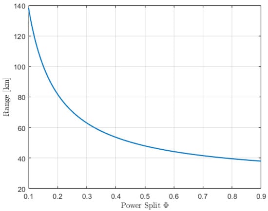
Figure 6.
Range using Equation (15) of [15].
Again, if the power split goes to zero, the range goes to infinity, which is inconsistent. If the airplane burns fuel only, its range must be limited in some way. So even the solution of linking the fuel burnt to the power split and state of charge is not correct. The authors formulate a second equation from Equation (15). Assuming that the power split is constant and moving the problem from mass consumption to energy consumption. As they say, this equation is useful for determining the necessary energy to achieve a specific range, so it should be read from left to right:
However, this form is useless for calculating the performance of a real airplane that already has a fixed and . Equation (17) of [15] just shows that transporting the energy in battery is more efficient than transporting it in fuel. This is due to the better efficiency of the electric power-train. Anyway, Equation (17) of [15] loses the reference to the fuel mass fraction and battery mass fraction and so on the airplane . Since the is so low, if increases then the increases, and so does the . A similar conclusion can also be obtained with the range equation reported in the recent paper [17].
4.2. Present New Range Equation
The range equation derived in this paper and shown in Figure 7 represents the two expressions of (32) and (33) as a function of the mechanical power split . Defining the hybridization level at the mechanical node results in an easier management of the power train than defining it at the power source level. The mechanical power is easier to measure than the fuel . Starting from = 0 and increasing it, we note that the range is limited by the red curve. This means that it is the fuel that runs out, while there is a residue of electric energy. Continuing we reach the corner point where a single value of is present and the range is maximum. This condition represents simultaneous exhaustion of electric energy and fuel. Continuing further the range is limited from the blue curve. This means that the batteries are running out and there is a residue of fuel. The maximum range solution can be numerically determined by imposing the condition . Moreover, the adequate set of , , values provides the condition of the maximum range.
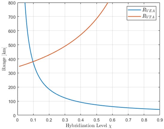
Figure 7.
Virtual airplane range for = 260 Wh/kg.
The range of the hybrid aircraft is given by the minimum between the VTA range and the VEA range as indicated in (40) and shown in Figure 8. Our best hypothesis is that the range of the hybrid version of the Dardo (with = 260 Wh/kg) is between 300 km and 350 km corresponding to a hybridization level of about , which also means an almost negligible impact on the reduction of emissions. By contrast, the original Dardo could fly 920 km according to this model (this observation is confirmed by the experimental data obtained with the real aircraft). In order to obtain a range comparable with the current one, an = 4000 Wh/kg would be needed, in correspondence to which we would also have a value of approximately , which would also mean a reduction in emissions. We can therefore conclude that at present, the hybrid version of the Dardo is of interest only from the point of view of increased safety during take-off, however, accepting a drastic reduction in the range. Increased range performance is possible considering the projection and development of future battery technologies. The authors of [2,18,19] predict values of on the order of 400–1000 Wh/kg by 2035, with which ranges between 400 km and 500 km begin to be feasible.
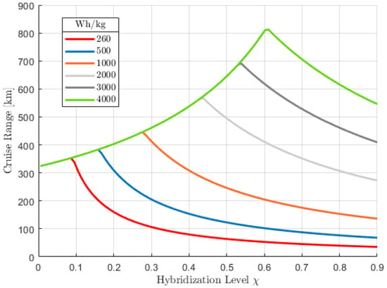
Figure 8.
Virtual airplane range envelope at different specific battery energy .
5. Validation with a Numerical Approach
A lot of data were available from the Dardo project, which were used to create a numerical model to approach the same problem and to obtain a verification of the analytical equation. This model is beyond the scope of this article and deserves separate discussion. In any case, a brief summary of the main concepts is given below.
The numerical model uses the equations of flight mechanics together with experimental data such as the operating curves of the propeller, internal combustion engine and electric motor. As input, it receives the aeroplane’s mass values, altitude, flight altitude, and degree of hybridization. The user also sets a limit on fuel consumption and energy stored in the batteries. The initial conditions are the fuel and energy level at the start of the cruise. The system of equations modeling the trend of residual fuel mass and residual energy is integrated over time. The integration is interrupted by a stopping criterion based on the fuel and state of charge (which is linked to the residual energy in batteries).
The algorithm solving the problem is reported in a simplified form in Figure 9. Assuming the fixed aircraft parameters as in Table 3, and varying the hybridization level from 0 to 1, Figure 10 has been obtained. Parameters have been tuned to represent the same aircraft. Efficiencies for the analytical model have been calculated as the mean value over time of the efficiencies computed by the numerical model. The results of the numerical model in Figure 10 match the analytical curve, demonstrating the validity of the proposed analytical formulation.
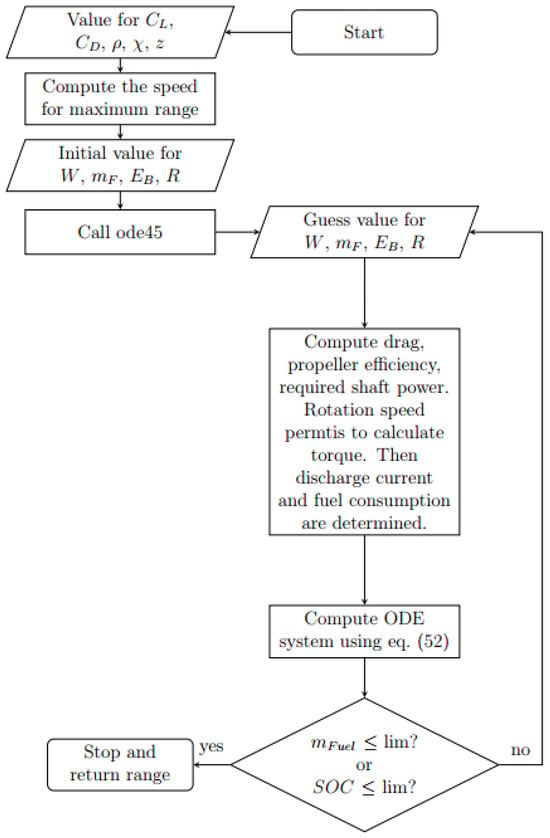
Figure 9.
Cruise algorithm implemented in MATLAB.

Table 3.
Hybrid airplane mass fractions and reference parameters for comparison with numerical model.
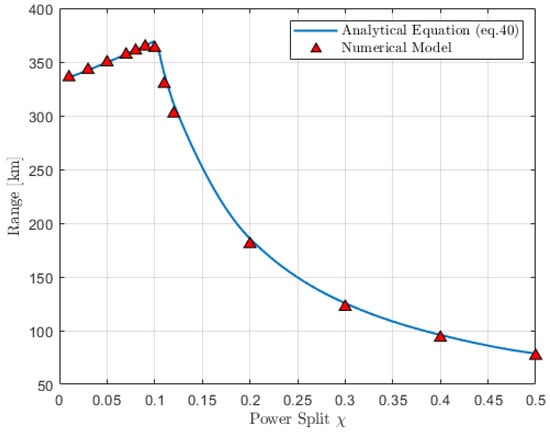
Figure 10.
Comparison between numerical and analytical models.
6. Conclusions
A new Range Equation based on comparison of Virtual Electrical Aircraft (VEA) and Virtual Thermal Aircraft (VTA) has been developed and validated with a reference composite VLA category aircraft. Range results are compared with previous developed range equations to show the differences with respect to the previous formulations and validated with a numerical flight mechanical model. A very good correlation between the present range equation and the numerical model was shown. The limitations of a hybrid aircraft have been highlighted with respect to different specific battery energy levels.
When used in the preliminary design phase of an aircraft from scratch, the analytical equations derived in this paper may be more complicated than others. Compared to others already found in the literature, the present range model require knowledge of a greater number of parameters such as the mass ratio of the batteries and the payload, which may be difficult to determine at an early design stage.
Author Contributions
Conceptualization, E.C. and D.P.; methodology, E.C. and D.P.; software, D.P. and E.C.; validation, D.P., E.C., V.S., V.M. and L.C.; formal analysis, D.P. and E.C.; investigation, E.C., D.P., V.S., L.C. and V.M.; data curation, D.P. and E.C.; writing – original draft, D.P., E.C., V.S., V.M. and L.C.; writing—review and editing, E.C., D.P., V.S., V.M. and L.C.; supervision, V.S., V.M. and L.C. All authors have read and agreed to the published version of the manuscript.
Funding
This research received no external funding.
Data Availability Statement
No new data were created or analyzed in this study. Data sharing is not applicable to this article.
Conflicts of Interest
The authors declare no conflict of interest.
Abbreviations
The following abbreviations are used in this manuscript:
| Proton Exchange Membrane Fuel Cell | |
| maximum take off mass | |
| empty operative mass | |
| battery pack mass | |
| payload mass | |
| propeller efficiency | |
| electric motor efficiency | |
| inverter efficiency | |
| thermal motor efficiency | |
| generator efficiency | |
| total power fraction | |
| power split | |
| E | aerodynamic efficiency |
| Virtual Electric Aircraft Range | |
| Virtual Thermal Aircraft Range | |
| Hybrid Aircraft Range | |
| Fuel energy density | |
| Battery energy density | |
| Battery initial cruise state of charge | |
| Battery end of cruise state of charge | |
| mass fractions |
References
- Bacchini, A.; Cestino, E. Key aspects of electric vertical take-off and landing conceptual design. Proc. Inst. Mech. Eng. Part G J. Aerosp. Eng. 2019, 234, 774–787. [Google Scholar] [CrossRef]
- Brelje, B.J.; Martins, J.R. Electric, hybrid, and turboelectric fixed-wing aircraft: A review of concepts, models, and design approaches. Prog. Aerosp. Sci. 2019, 104, 1–19. [Google Scholar] [CrossRef]
- Hepperle, M. Electric Flight—Potential and Limitations. In Proceedings of the NATO MPAVT-209-09, Energy Efficient Technologies and Concepts of Operation, Lisbon, Portugal, 22–24 October 2012. [Google Scholar]
- Romeo, G.; Cestino, E.; Correa, G.; Borello, F. A Fuel Cell Based Propulsion System for General Aviation Aircraft: The ENFICA-FC Experience. SAE Int. J. Aerosp. 2011, 4, 724–737. [Google Scholar] [CrossRef]
- Correa, G.; Santarelli, M.; Borello, F.; Cestino, E.; Romeo, G. Flight test validation of the dynamic model of a fuel cell system for ultra-light aircraft. Proc. Inst. of Mech. Eng. Part G J. Aerosp. Eng. 2015, 229, 917–932. [Google Scholar] [CrossRef]
- Romeo, G.; Cestino, E.; Pacino, M.; Borello, F.; Correa, G. Design and testing of a propeller for a two-seater aircraft powered by fuel cells. Proc. Inst. Mech. Eng. Part G J. Aerosp. Eng. 2012, 226, 804–816. [Google Scholar] [CrossRef]
- Schmollgruber, P.; Döll, C.; Hermetz, J.; Liaboeuf, R.; Ridel, M.; Cafarelli, I.; Atinault, O.; François, C.; Paluch, B. Multidisciplinary Exploration of DRAGON: An ONERA Hybrid Electric Distributed Propulsion Concept. In Proceedings of the 2019 AIAA Aerospace Sciences Meeting, San Diego, CA, USA, 7–11 January 2019. [Google Scholar] [CrossRef]
- C.F.M.Air. Blu Spark Hybrid Technology. Available online: https://cfm-air.net/projects/blu-spark-hybrid-technology/ (accessed on 8 October 2023).
- Diamond Aircraft. Diamond Aircraft Presents the World’s First Serial Hybrid Electric Aircraft “DA36 E-Star”. Available online: https://www.diamondaircraft.com/ (accessed on 8 October 2023).
- Raymer, D.P. Aircraft Design: A Conceptual Approach, 6th ed.; AIAA: Reston, VA, USA, 2018. [Google Scholar]
- Adu-Gyamfi, B.A.; Good, C. Pre-design strategies and sizing techniques for dual-energy aircraft. Aircr. Eng. Aerosp. Technol. 2014, 86, 525–542. [Google Scholar] [CrossRef]
- Finger, F.; Braun, C.; Bil, C. Initial Sizing Methodology for Hybrid-Electric General Aviation Aircraft. J. Aircr. 2019, 57, 245–255. [Google Scholar] [CrossRef]
- Wroblewski, G.E.; Ansell, P.J. A Bréguet Range Equation for Hybrid-Electric Jet Aircraft Sizing and Analysis. In Proceedings of the 2020 AIAA/IEEE Electric Aircraft Technologies Symposium (EATS), New Orleans, LA, USA, 26–28 August 2020; pp. 1–24. [Google Scholar]
- Kiesewetter, L.; Shakib, K.; Singh, P.; Rahman, M.; Khandelwal, B.; Kumar, S.; Shah, K. A holistic review of the current state of research on aircraft design concepts and consideration for advanced air mobility applications. Prog. Aerosp. Sci. 2023, 142, 100949. [Google Scholar] [CrossRef]
- de Vries, R.; Hoogreef, M.F.M.; Vos, R. Range Equation for Hybrid-Electric Aircraft with Constant Power Split. J. Aircr. 2020, 57, 552–557. [Google Scholar] [CrossRef]
- Rohacs, J.; Rohacs, D. Energy coefficients for comparison of aircraft supported by different propulsion systems. Energy 2020, 191, 116391. [Google Scholar] [CrossRef]
- Batra, A.; Raute, R.; Camilleri, R. On the Range Equation for Hybrid-Electric Aircraft. Aerospace 2023, 10, 687. [Google Scholar] [CrossRef]
- Finger, F.; de Vries, R.; Vos, R.; Braun, C.; Bil, C. A Comparison of Hybrid-Electric Aircraft Sizing Methods. In Proceedings of the AIAA SciTech 2020 Forum, Orlando, FL, USA, 6–10 January 2020; pp. 1–31. [Google Scholar]
- Adu-Gyamfi, B.A.; Good, C. Electric aviation: A review of concepts and enabling technologies. Transp. Eng. 2022, 9, 100134. [Google Scholar] [CrossRef]
Disclaimer/Publisher’s Note: The statements, opinions and data contained in all publications are solely those of the individual author(s) and contributor(s) and not of MDPI and/or the editor(s). MDPI and/or the editor(s) disclaim responsibility for any injury to people or property resulting from any ideas, methods, instructions or products referred to in the content. |
© 2023 by the authors. Licensee MDPI, Basel, Switzerland. This article is an open access article distributed under the terms and conditions of the Creative Commons Attribution (CC BY) license (https://creativecommons.org/licenses/by/4.0/).