Article

A Model and Methodology for Probability Assessment of Foreign Objects Crossing through an Aircraft Propeller

1
China Electronic Product Reliability and Environmental Testing Research Institute, Guangzhou 511370, China
2
Guangdong Provincial Key Laboratory of Electronic Information Products Reliability Technology, Guangzhou 511370, China
*
Authors to whom correspondence should be addressed.
Aerospace 2023, 10(11), 925; https://doi.org/10.3390/aerospace10110925
Submission received: 14 August 2023 / Revised: 10 October 2023 / Accepted: 23 October 2023 / Published: 30 October 2023
(This article belongs to the Section Aeronautics)

Abstract

:
Propeller-crossing probability analysis is crucial for evaluating the impact resistance and foreign object exclusion capability of turboprop engines. However, due to the complex structure of the propeller and the uncertainties associated with the impact location as well as the flight attitude of the foreign object, developing a comprehensive model for analyzing the propeller-crossing process remains a significant challenge. This paper presents a novel simulation method that can obtain the probability of a foreign object successfully crossing the propeller using a high-fidelity structure model of the propeller and a comprehensive substituted model of the foreign object. To validate the performance of the proposed method, an analytical model is developed that takes into account the spatial structure constraints of the propeller and the foreign object. The proposed method is applied to calculating the probability of bird ingestion, and the results reveal that the increments in flight speed and aspect ratio of the bird have opposite effects on the propeller-crossing probability, and the values eventually converge to a constant value.

1. Introduction

Among general aviation options, turboprop aircraft stand out as a highly economical means of global transportation. However, their operations may be impacted by foreign objects that may arise during all stages of flight, including hail and ice [1,2] while traversing in clouds or icing environments, birds [3,4] during takeoff and landing maneuvers, and even sand particles [5,6] originating from runways or inclement weather. Recently, unmanned aerial vehicles (UAVs), as foreign objects, have posed a growing threat to the safety management of aircraft operations. The potential hazards posed by foreign objects to turboprop engines manifest in two forms: a foreign object’s impact on the aircraft, that can inflict harm on its structural or component functions [7,8,9]; and the ingestion of foreign objects through the propeller and intake, engendering detrimental consequences that imperil both the engine and the entire aircraft’s safety [10,11]. These outcomes pose a significant threat to aviation safety and may result in substantial economic losses. As a result, the foreign object damage (FOD) problem is a significant challenge faced by the aviation engineering community, and aircraft equipped with turboprop engines must comply with related requirements in civil aviation airworthiness regulations [12,13].
During an impact event, a foreign object can strike an aircraft from any direction, potentially causing damage to any critical part of the aircraft. The primary form of damage inflicted on an aeronautical structure by a foreign object is attributed to the transient high-pressure load generated at the collision surface, which surpasses the aircraft or aircraft component’s structural strength. This generates substantial deformation and damage at the point of impact, directly impacting flight safety. As a result, the dynamic response mechanism of foreign object impact or ingestion has received considerable attention within the aviation field, leading to a multitude of research endeavors on impact load models [14,15,16], damage mechanisms [17,18], and numerical simulations [19,20,21]. These investigations seek to effectively capture and characterize the influence of foreign objects, which must be considered in the design and verification of aircraft and aero engines.
Regarding the core engine, particularly those in turboprop aircraft, the FOD problem can only occur if the object is ingested by the engine, which requires the foreign object to cross the propeller that is rotating in front of the engine inlet first, as illustrated in Figure 1. However, the probability of propeller crossing is still an area of limited research within the aviation field. Ruiz-Calavera [22] presented a simplified methodology for evaluating the effectiveness of a spinner anti-ice system in an A400M. The research utilized a kinematic model developed by the propeller manufacturer RFHS to estimate the probability that an ice slab/sheet can pass through the propeller without being struck by the blades, involving comparing the time it took for the ice mass to traverse the blade row to the time for a single blade passage, without considering the actual geometry of the propeller or the thickness of the blades. Metz [23] assumed that the probability of a bird impact event is related to the position and movement uncertainty of the bird. However, his model only focuses on the collision volume of the bird and fails to account for the potential scenario where foreign objects could pass through the gaps between the blades. Jiang [24] supposed that the propeller’s movement could serve as a form of protection against bird strikes on the windshield mounted behind it. The probability of the bird flying perpendicular through the rotary surface of the propeller was proposed as an index for evaluating the windshield’s resistance to bird strikes. In addition, the engine intake systems of turboprop aircraft are often designed with a bypass duct, and research in this field has mainly focused on the aerodynamic issue of the geometric shape designation of the intake system [25,26]. Mi and Zhan [27] performed a numerical simulation to investigate the performance of a novel intake system in excluding foreign objects, but in their hypothesis the foreign objects are assumed to be ingested through the center of the intake entrance. To date, few studies have considered scenarios in which foreign objects cross the propeller and enter the engine from arbitrary positions within the intake entrance.
In summary, the propeller-crossing probability serves as a critical parameter for evaluating the probabilistic impact risk of the propeller and intake system, as well as assessing the foreign object exclusion capabilities of turboprop engines. Despite its importance, there has been a lack of research on this topic. This paper introduces several key innovations and research ideas, which are as follows:
  • Development of a novel concentric-spherical foreign object substitution model that offers greater versatility and can accommodate various existing configurations of foreign objects;
  • Proposal of a numerical simulation algorithm for determining foreign object collisions based on the high-fidelity FEA model of the propeller. This algorithm enables accurate quantification of the probability of foreign object collisions or the traversal of the engine propeller;
  • Derivation of analytical models for evaluating the propeller-crossing probability in typical foreign object substitution configurations. These models are combined with the proposed numerical simulation algorithm to validate its usability and accuracy.
The FOD issue has been extensively investigated in various fields, such as wind energy, with a primary focus on developing collision-risk models (CRMs) to evaluate the probability that foreign objects may impact the turbine blade. In these studies, researchers agree that collision events are avoidable if foreign objects can successfully pass through the obstacle. Due to the high cost of real collision tests, researchers tried to establish analytical models for risk evaluation. These models [28] have been utilized in diverse scenarios, including birds and wind turbines, marine mammals and marine renewable energy devices, tidal stream turbines, fish and turbines, as well as shipping collisions with both stationary and moving objects. Tucker [29] developed a simplified model in 1996, taking into account factors such as the bird’s dimensions and flight speed, and the wind turbine blade’s radial position, shape, and rotational speed. The model disregarded the blade thickness and represented the wind turbine as a curved surface, while the bird was modeled as a two-dimensional rectangle moving parallel or perpendicular to the blade’s rotation plane. Tucker’s model was subsequently expanded by integrating flight height as a parameter to characterize the distribution of birds [30]. Bolker [31] developed a model for the geometry of wind farms to determine the average number of turbines encountered by birds. Podolsky [32] and Holmstrom [33] improved the bird model by taking into account its shape and oblique angles of approach. To mitigate the high cost and time consumption associated with conducting actual impact tests, many researchers have endeavored to develop analytical geometric models for illustrating the foreign-body impact process. Nevertheless, most of the models above have employed a simplified two-dimensional representation of the bird and wind turbine fan to enable easier determination of collision events. It is worth noting that Han [34] proposed a covariance ellipsoid model in three-dimensional space for collision warning of satellites, which showing high-precision performance.
This paper is organized as follows: Section 2 gives the model assumptions and the simulation modeling approach for analyzing the propeller crossing of foreign objects. In Section 3, an analytical geometric model is developed for validation purposes, and a comparative analysis with the proposed model is conducted under specific conditions. In Section 4, the proposed method and model are applied to a scaled model of a turboprop engine to demonstrate their applicability. The main conclusions are summarized in Section 5.

2. Methodology

The purpose of this article is to develop a model for calculating the propeller-crossing probability based on the essence of collision, that the propeller blades occupy the same space as a foreign object during the time it takes the object to pass through the rotor-swept volume of the propeller. Accordingly, the model can be established by the following terms:
(1) Modeling the rotational motion of the propeller. Due to the complex aerodynamic phenomena that influence the rotation of the propeller, including factors such as geometry configurations, rotary speed, blade number, aerodynamic pressures, etc, the propeller is simplified to be composed of a spinner and propeller blades rotating at a constant speed around the central axis of the spinner.
(2) Modeling the foreign object and its trajectory. Typical foreign objects (like birds, hail, dust, etc.) are usually represented as different two-dimensional geometries (circles, rectangles, cruciform, etc.) and assumed to fly perpendicular to the rotary propeller. A more comprehensive model is needed to unify the various-shaped substituted models of foreign objects and to consider their trajectories, including the initial position, attitude angle, and flight velocity.
(3) Specifying the crossing criteria based on the spatial constraints of the rotary propeller and foreign object’s flight trajectory. Given the challenge of establishing a realistic model for the crossing process, high-fidelity finite element analysis (FEA) and numerical simulation techniques are employed to transform the process into impact snapshots at discrete time points. The distance between the foreign object and the propeller blade is calculated at each time point to determine whether a collision event has occurred.

2.1. Model Assumption

Significant emphasis is placed on the process of a foreign object passing through the turboprop propeller in this paper. Several assumptions have been proposed:
(1) Both the foreign objects and the turboprop propeller are rigid structures.
(2) Owing to the brief duration of the foreign object’s crossing through the propeller rotation plane, it is assumed that the aerodynamic effects generated by the propeller can be disregarded.
(3) Foreign objects may fly towards the propeller from any position, at any speed/angle, and the aircraft does not affect their flight path.
(4) Only one foreign object flies towards the propeller at a time, and the case of multiple objects is neglected.
(5) A collision is defined as the first instance in which a foreign object makes contact with any part of the propeller, without taking into account possible subsequent contacts or the scenario in which the object is cut by the propeller blade.

2.2. Propeller-Crossing Modeling

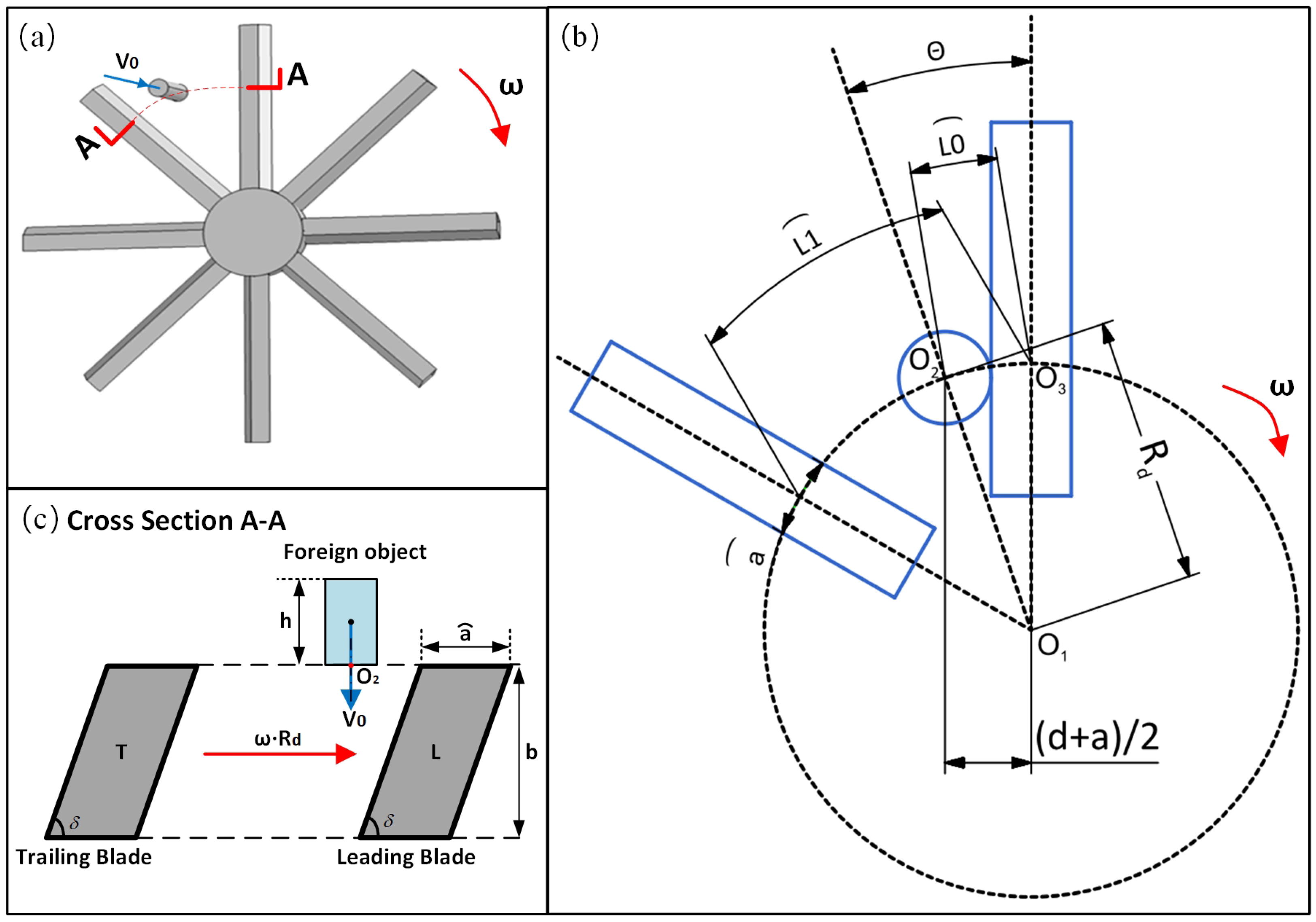
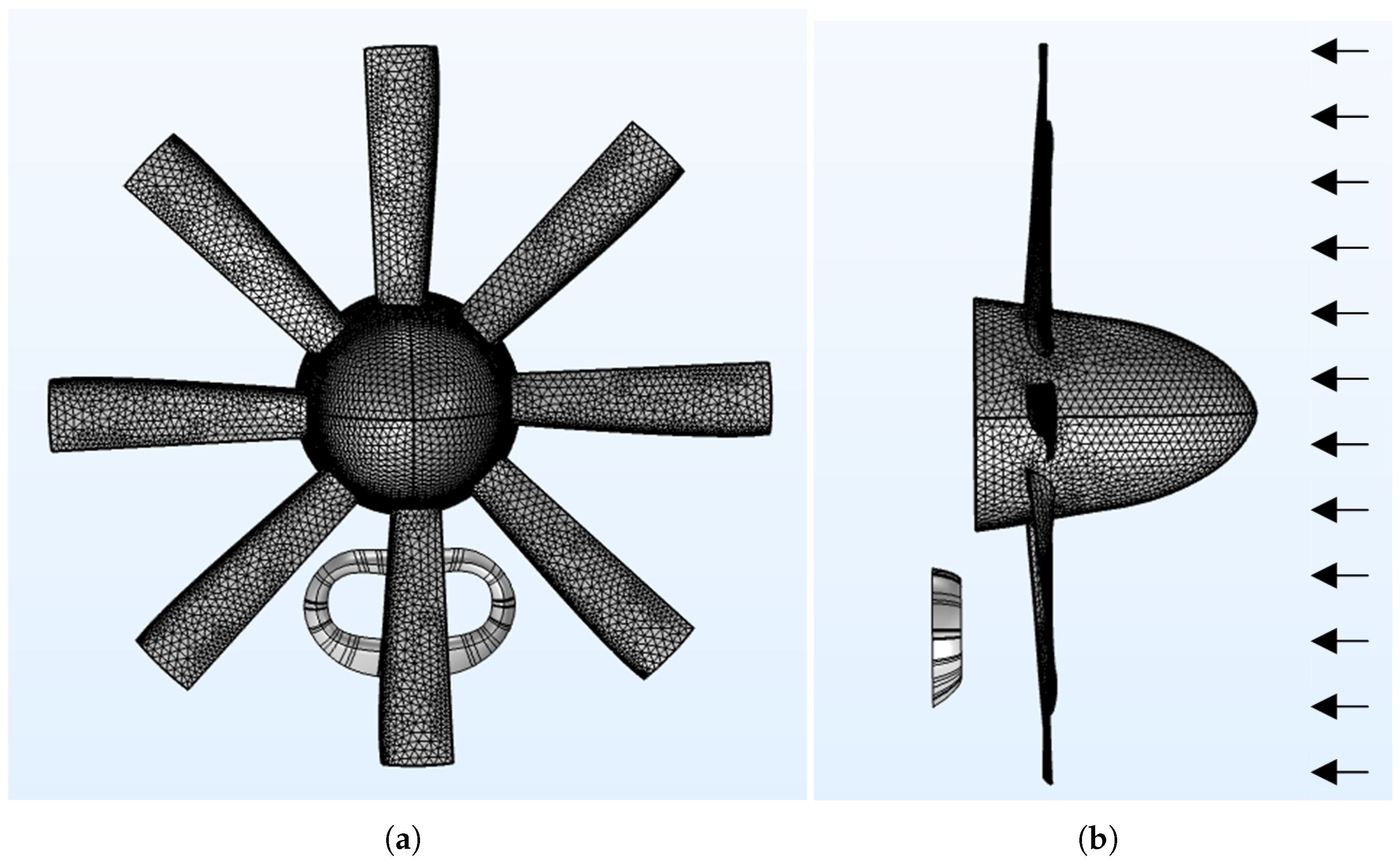
2.2.1. Discretization Model of Turboprop Propeller

Based on the high-fidelity FEA model of a turboprop propeller, the set of time-varying spatial coordinate points of the propeller and its blades can be obtained through the finite element mesh generation methods. A three-dimensional coordinate system is established according to a 3D model of the propeller, in which:
(1) the center of the spinner’s bottom is defined as the origin;
(2) the x-axis is aligned with the spinner’s central axis and is orientated towards the front of the spinner;
(3) the y-z plane denotes the specific plane in which the bottom of the spinner is situated.
The surface mesh is applied to the propeller model and the coordinate data of the grid nodes are collected to represent the outer surface ( Ω ) of the real propeller, as shown in Figure 2.
According to the coordinate system, the arbitrary node K Ω has coordinates x K , y K , z K , which is equal to x K , y K + z K i in complex form. When the propeller rotates around the x-axis, the x coordinate of K remains constant while its y and z coordinates will change periodically; the boundaries of the propeller on the x-axis are defined as x K , y K + z K i .

2.2.2. Concentric-Spherical Foreign Object Model

Researchers have long worked on developing a sufficiently simplified and consistent model to represent the complex geometrical configurations of various foreign objects. These five configurations [1,22,35], which are typical of bird, hail, and ice geometries, are shown schematically in Figure 3.
In this article, a concentric-spherical model is proposed to unify the different representations of foreign object configurations. This model is established based on the typical foreign-object-substituted models and consists of an inscribed sphere and a circumscribed sphere; the straight-ended cylinder bird model is taken as an example as Figure 4a shows; the other typical models are shown schematically in Figure 4b–e, and their geometrical parameters are listed in Table 1.

2.2.3. Crossing Process Modeling

Using the concentric-spherical model, the propeller-crossing process of the foreign object can be depicted as a specific portion of the model centroid’s trajectory within the propeller coordinate system (xyz), as the red solid line shown in Figure 5a; where θ is the angle between the trajectory and the x-axis. According to the boundaries of Ω , the possible collision location on the trajectory should be x min R , x max + R relative to the x-axis, implying that the initial and termination points of all trajectories are assumed to be placed on the plane Π 1 : x , y , z x = x max + R and Π 2 : x , y , z x = x min R , respectively. The radius of the inscribed sphere (r) is employed as the unit of measurement to divide the trajectory into discretized segments, indicating the step length of the crossing process, and thus, we have,
Δ l = λ · r , 0 < λ < 1 Δ t = Δ l Δ l V 0 V 0
where V 0 is the flight velocity, Δ l (step length) and Δ t (step time) denote the length of each segment and the time consumed in each segment, respectively. Hence, the dataset of model centroid coordinates C n during crossing can be acquired, the step number n should take values of 1 , 2 , , m + 1 , and m can be calculated by
m = x max x min + 2 R x max x min + 2 R Δ l cos θ Δ l cos θ
where · represents an operator in which the figure is rounded down to the nearest integer. Given the angular velocity of the propeller, ω , the data set of an arbitrary node’s coordinates K n on the propeller surface can be obtained, while the initial coordinates K 0 x K 0 , y K 0 , z K 0 can be generated from the stationary propeller.
Furthermore, it should be noted that the flight attitude of the foreign object is also defined based on the propeller coordinate system. The attitude angles of a foreign object can be illustrated by the angles α 1 , α 2 , α 3 between its central axis and the x-, y-, and z-axes, respectively, as depicted in Figure 5b.

2.3. Criteria for Propeller Crossing

Based on the established models, it can be determined whether the foreign object can pass through the rotating propeller depending on the distances between the concentric spheres and the points on the propeller surface. Therefore, the criteria for the crossing can be set as follows:
L 1 : d C K > R L 2 : r > d C K L 3 : R d C K r
in which d C K represents the distance between the identical centroid (C) of concentric spheres and a certain point (K) on the propeller surface ( Ω ). The value of d C K at a certain step n can be calculated by
d C K n = d x 2 + d y 2 + d z 2 = x C n x K n 2 + y C n y K n 2 + z C n z K n 2
where d x , d y , and  d z represent the absolute values of the difference between the point coordinates of C n and K n in the three coordinate axes, respectively.
For criterion L 1 , the distances between the points on the centroid’s trajectory and all nodes on the propeller surface must be larger than the radius of the circumscribed sphere (R), indicating that no collision occurs at that moment. On the contrary, if any one of the distances satisfies the criterion L 2 , it implies that the collision has occurred. For the other scenarios, that comply with L 3 , additional criteria need to be established by considering more characteristics, such as the attitude angles and configurations of the foreign object.

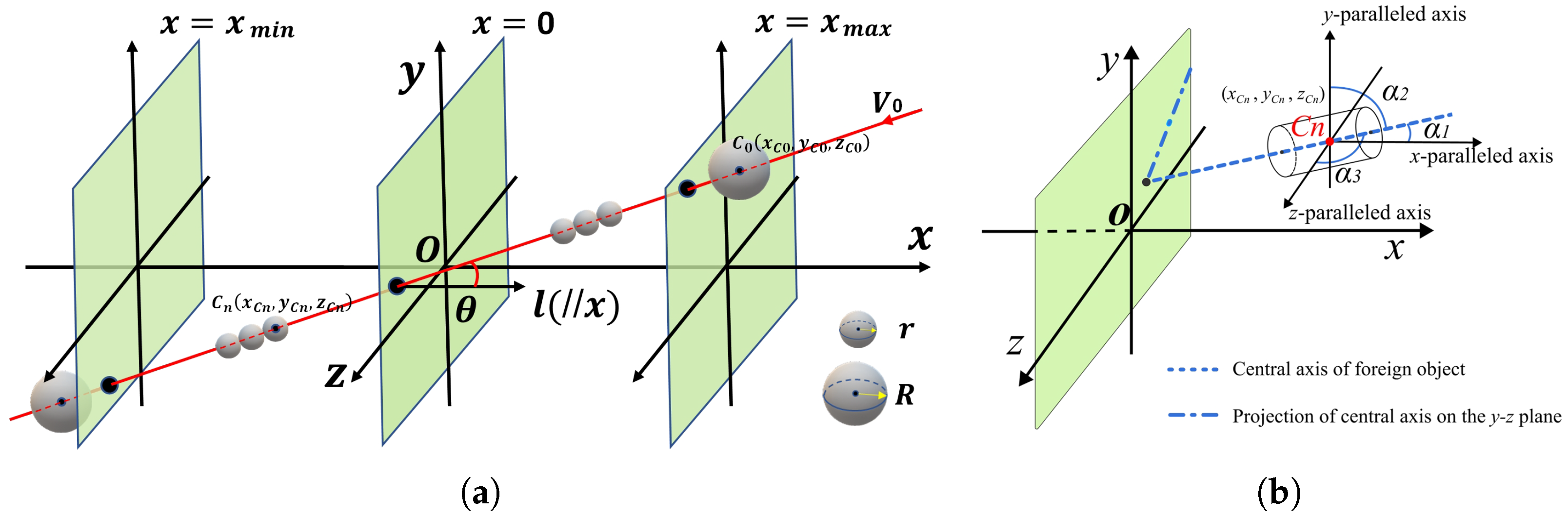
2.3.1. Consideration of the Flight Trajectory

The foreign object may collide with the propeller from any orientation, which results in a complex equation for the trajectory of the model centroid in the propeller coordinate system. However, the initial rotation angle of the propeller has no effect on the probability of propeller crossing. To facilitate the acquisition of the centroid’s real-time coordinates during flight, it is recommended to perform a coordinate transformation on the original propeller coordinate system.
Referring to Figure 6a, θ represents the angle formed between the flight trajectory and the x-axis, while β indicates the angle between the y-axis and the projection of the flight trajectory onto the yz plane. Let v ( f x , f y , f z ) be the directional vector of the flight trajectory, then θ and β have the following relationships:
θ = arccos f x f x 2 + f y 2 + f z 2 , 0 < θ < π 2 β = arctan f z f z f y f y , π 2 < β < π 2
By rotating the coordinate system around the x-axis by an angle of β , the translational motion of the foreign object centroid can be transformed into a linear motion parallel to the new x y plane, as illustrated in Figure 6b. The transformed coordinates of the foreign object centroid can be calculated as
x C n y C n z C n = 1 0 0 0 cos β sin β 0 sin β cos β x C n y C n z C n
hence,
x C n = x C n = x max + R n · Δ l · cos θ , n = 1 , 2 , , m + 1 y C n = x C n x C 0 · tan θ + y C 0 = x C n x C 0 · tan θ + y C 0 · cos β + z C 0 · sin β z C n = z C 0 = z C 0 · cos β y C 0 · sin β
The spatial coordinates of any arbitrary node K n x K n , y K n + z K n i on the outer surface of the propeller ( Ω ) in the transformed coordinate system can be obtained as follows:
x K n = x K n y K n = M K cos φ K n + β z K n = M K sin φ K n + β
in which M K and ϕ K denote the modulus and argument of the complex number, respectively, and  M K e i · φ K n = y K n + z K n i . Given the initial x K 0 , y K 0 + z K 0 i , we have
M K = y K 0 2 + z K 0 2 φ K n = φ K 0 + ω · n · Δ t φ K 0 = a r c tan ( z K 0 z K 0 y K 0 y K 0 ) , n = 1 , 2 , , t + 1

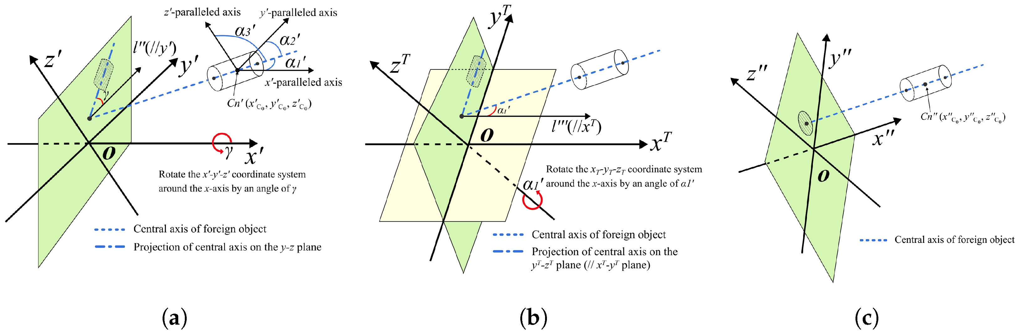
2.3.2. Consideration of the Attitude Angles

The attitude angles of the foreign object in the x y z coordinate system, as shown in Figure 7a, can also be obtained by substituting the direction vector of the foreign object’s central axis cos α 1 , cos α 2 , cos α 3 into Equation (6) using the conversion relationship
cos α 1 = cos α 1 cos α 2 = cos α 2 cos β + cos α 3 sin β cos α 3 = cos α 2 sin β + cos α 3 cos β
where α 1 , α 2 , α 3 are the transformed attitude angles, indicating the angles between the foreign object’s central axis and the x -, y -, and  z -axes, respectively. It should be noted that the central axis passing through the origin does not affect these angles. Moreover, the angle between the projection of the central axis onto the y z plane and the y -axis was defined as γ , which equals arctan cos α 3 cos α 3 cos α 2 cos α 2 .
To facilitate the acquisition of the surface equation of a foreign object, it is necessary to transform the coordinate system again. First, the ( x y z ) coordinate system is rotated around the x -axis by an angle of γ to obtain a temporary coordinate system ( x T y T z T ). Then, the temporary coordinate system should be rotated around the z T -axis by an angle of α 1 . This transformation results in the creation of a coordinate system ( x y z ) that satisfies the following conditions simultaneously: the central axis of the foreign object should be (1) parallel to the x -axis; and (2) perpendicular to the y z plane, as shown in Figure 7c.
Consequently, the coordinate values of all points on the foreign object and propeller in the coordinate systems before and after transformation have the following relationship:
x y z = cos α 1 sin α 1 · cos γ sin α 1 · sin γ sin α 1 cos α 1 · cos γ cos α 1 · sin γ 0 sin γ cos γ x y z

2.3.3. Refined Criteria for Typical Foreign Object Configurations

In the coordinate system x y z , the mathematical expressions of d x , d y , and  d z are transformed as
d x n = x C n x K n d y n = y C n y K n d z n = z C n z K n
Consequently, the criterion L 3 can be refined according to the configurations of the foreign object, as listed in Table 2. Similar to L 2 , collision will occur as long as the refined criteria are satisfied at any step of the flight trajectory. Otherwise, the foreign object is treated as crossing the propeller successfully.

2.4. Algorithm for Propeller-Crossing Probability

By obtaining the FEA model of the propeller and setting the initial motion parameters of the foreign object and propeller, we can calculate the probability of the foreign object crossing through the propeller using Algorithm 1 as follows.
Algorithm 1: Calculating the Probability of Propeller Crossing
Aerospace 10 00925 i001

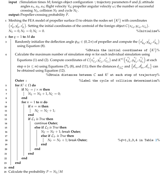
3. Scientific Demonstration

In order to establish the validity of the proposed model, it is imperative to conduct a demonstration aimed at assessing the accuracy of the crossing probability. To achieve this, we have developed an analytical geometric model founded upon the movements of idealized geometries. This analytical model facilitates the characterization of crucial crossing conditions and furnishes analytical solutions for the propeller-crossing probability through cost-effective calculations, circumventing the high-expense associated with real-world tests. Subsequently, we conduct simulations on predefined foreign object configurations, using the analytical solutions as a benchmark, to affirm the precision and effectiveness of the proposed methodology by comparing the analytical and simulation outcomes.

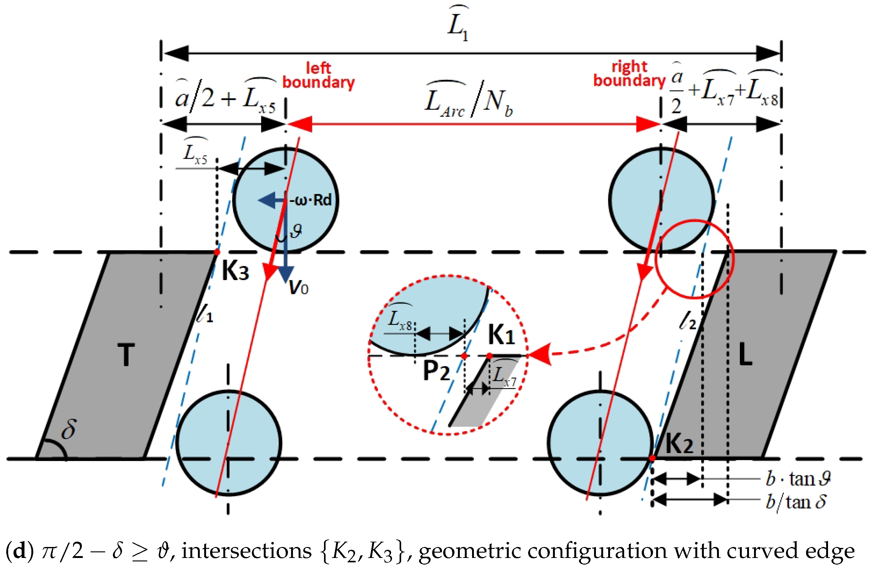
3.1. Geometric Relations in the Crossing Process

Assuming a foreign object approaches the surface of a rotary propeller, which has N b parallelepiped blades, in a vertical trajectory that coincides with its central axis, as illustrated in Figure 8a, we consider the fly-in position of the foreign object centroid to be represented by O 2 . Let the distance between O 2 and the propeller’s rotation center O 1 be defined as R d . By constructing a circle with O 1 as the center and R d as the radius, the arc length can be obtained by cutting the blade and represented by a . In addition, the arc length between adjacent blades is denoted by L 1 . Assuming the foreign object is tangent to a certain blade, the distance between O 2 and the blade’s central axis can be calculated as ( d + a ) / 2 . We further denote the intersection of the blade’s central axis and the circle as O 3 , with the arc length between O 2 and O 3 represented by L 0 , and the corresponding angle as Θ, as illustrated in Figure 8b.
Figure 8c displays the top view of the cross-section (AA) obtained by converting the curved cross-section of the foreign object and its adjacent blades along the circle with O 1 as the center and R d as the radius; the speed of the blades is assumed to be ω · R d . We define the leading blade as the blade that is positioned ahead of the adjacent blades in the speed direction, while the other blade is the trailing blade. The thickness and apex angle of the blade are denoted by b and δ , respectively.
The comprehensive derivation of the analytical model is presented in Appendix A. It is important to emphasize that while the analytical model boasts ease of calculation, it is constrained by two limitations. Firstly, it is exclusively suited for modeling the crossing process of objects moving vertically towards the rotating surface of the propeller. Secondly, the analytical model assumes an idealized propeller shape. Conversely, the simulation model offers versatility, enabling simulations for various directions and propeller shapes.

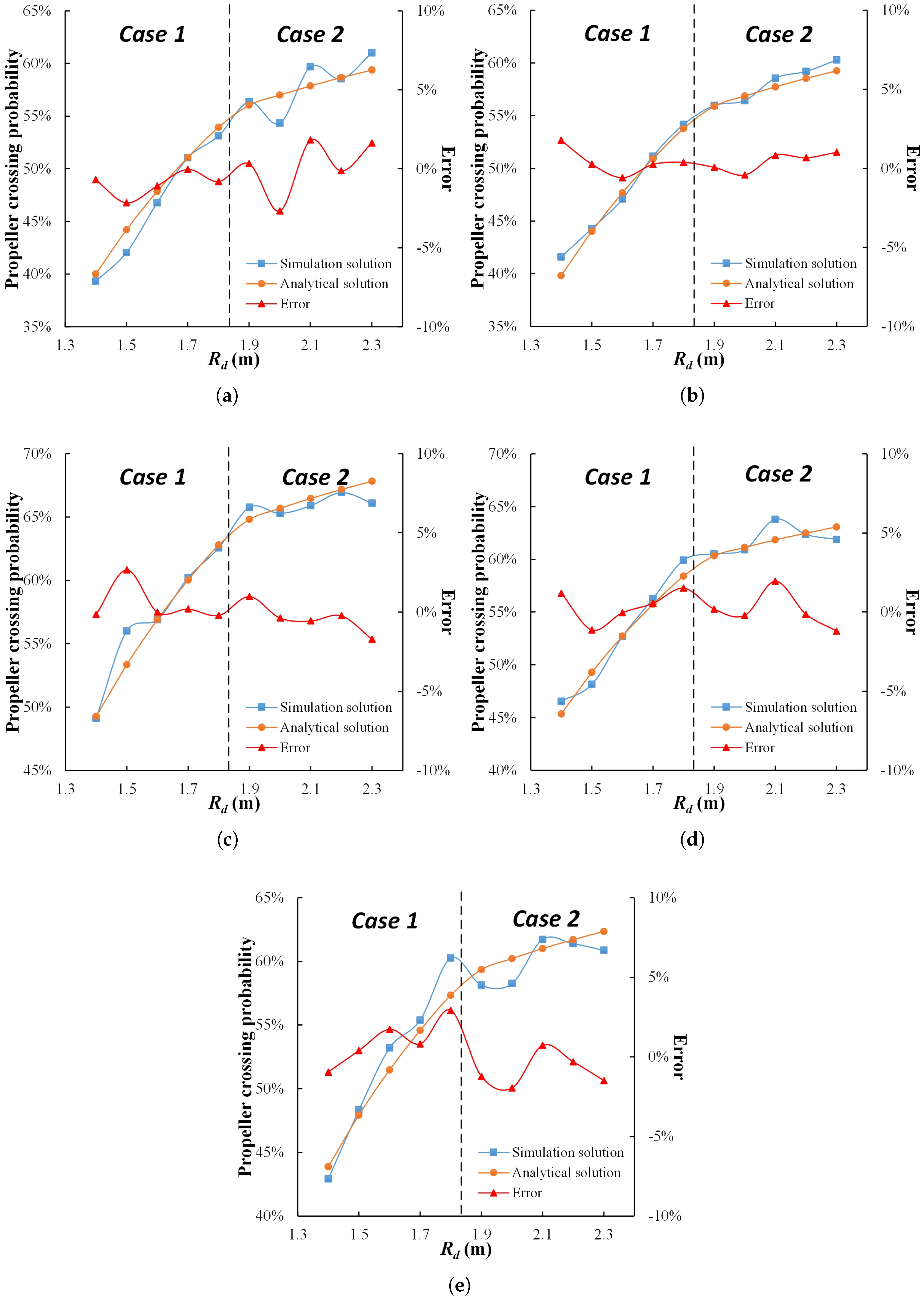
3.2. Model Validation

To validate the method proposed in Section 2, a comparative study is performed. We assume the idealized model parameters are V 0 = 180 m/s, ω = 96.34 rad/s, a = 0.4 m, b = 0.2 m, δ = 45 , N b = 8 , as well as the shape parameters of typical foreign objects listed in Table 3, and consider R d ranges from 1.4 to 2.3 m, with a length interval of 0.1 m. We first determine the crossing process scenario based on the geometric shape of typical foreign object configurations, and then identify the corresponding crossing boundaries with respect to R d , according to Equation (A2). For each typical foreign object configuration, we calculate the analytical solution of the propeller-crossing probability using Equations (A4)–(A7) and (A1). To verify the accuracy of our proposed method, we conduct simulations under identical parameters and compare the results to the analytical solutions. Under the idealized model assumptions, the trajectory parameters of the foreign object are initialized with θ = 0 and β = 0 in the simulation, while the attitude parameters are set to α 1 = 0 , α 2 = 90 , and α 3 = 90 . The simulation for each configuration is repeated 1000 times.
For illustration, a comparison between the simulation and analytical solutions of the propeller-crossing probability at each R d for five typical foreign object configurations is shown in Figure 9. The difference between the values of the simulation solution and analytical solution is considered the error in the proposed method.
According to Equation (A2), the magnitude of ϑ will increase with R d . As a result, the analytical solution formula for the propeller-crossing boundaries will change from the formula in case 1 to that in case 2 at R d = 1.8683 m, given the foreign object’s flight speed V 0 and propeller rotation speed ω . As can be seen, the propeller-crossing probability continues to increase as R d rises, but the upward trend slows down after the transformation of the solution formula in different cases. As Figure 9 shows, the errors between the analytical and simulation solutions for all configurations are within ± 3 % , indicating that the proposed method in this paper has a significant level of accuracy.
Since the sphere configuration model often substitutes for smaller ice-based foreign objects, its size parameter is set to roughly half that of the other configurations. As Figure 9c shows, this model exhibits the highest propeller-crossing probability, which is consistent with common sense expectations. By checking the remaining subplot in Figure 9 for the other configurations with approximated shape dimensions, we observe that the analytical solution for the propeller-crossing probabilities in scenario 2 exceed those of scenario 1 at the same R d . Furthermore, the gap between the scenarios decreases monotonically as R d increases, though this trend is less evident in the simulation solutions, which may be related to the number of simulations conducted.

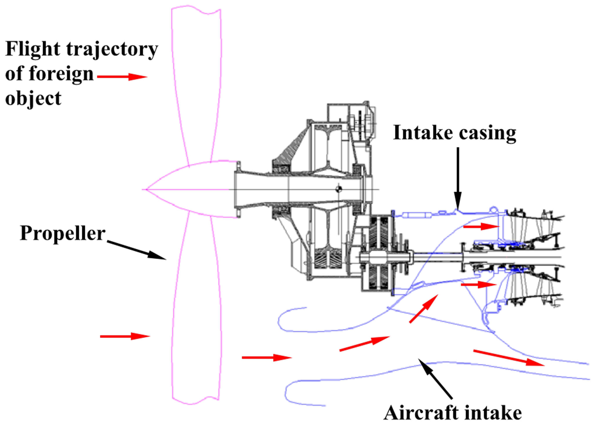
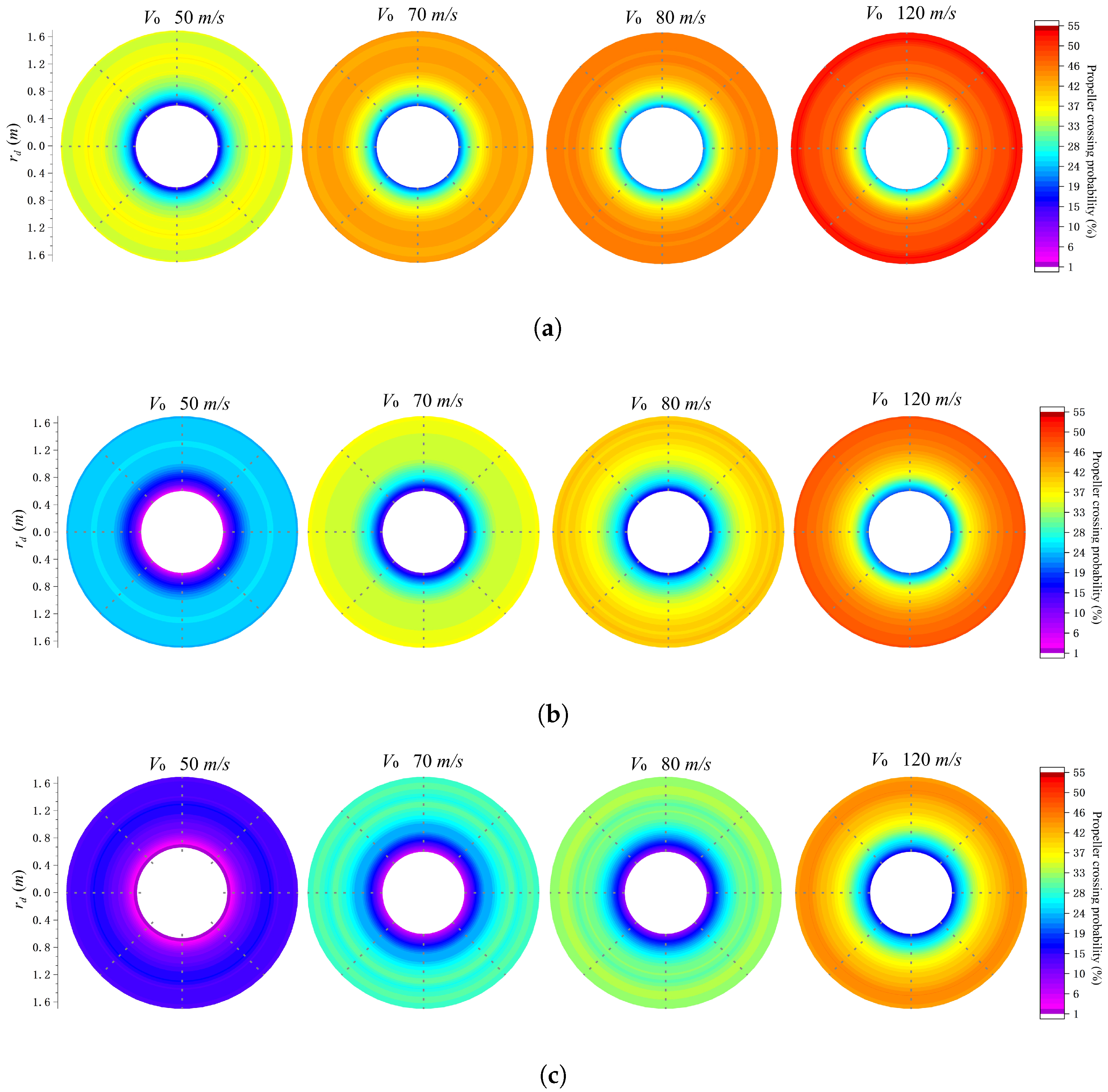
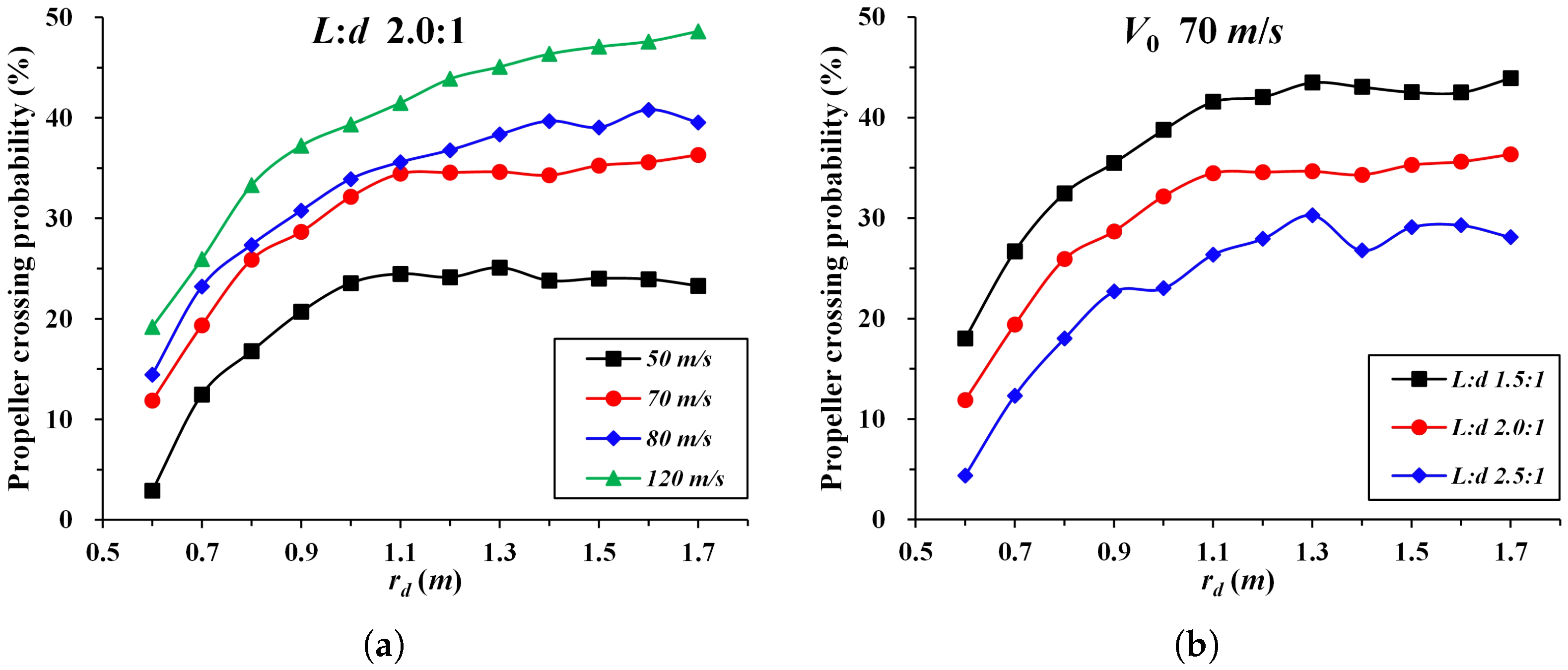
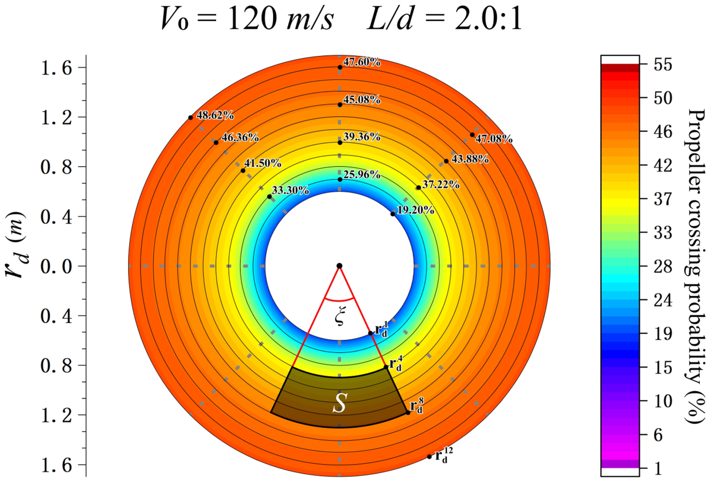
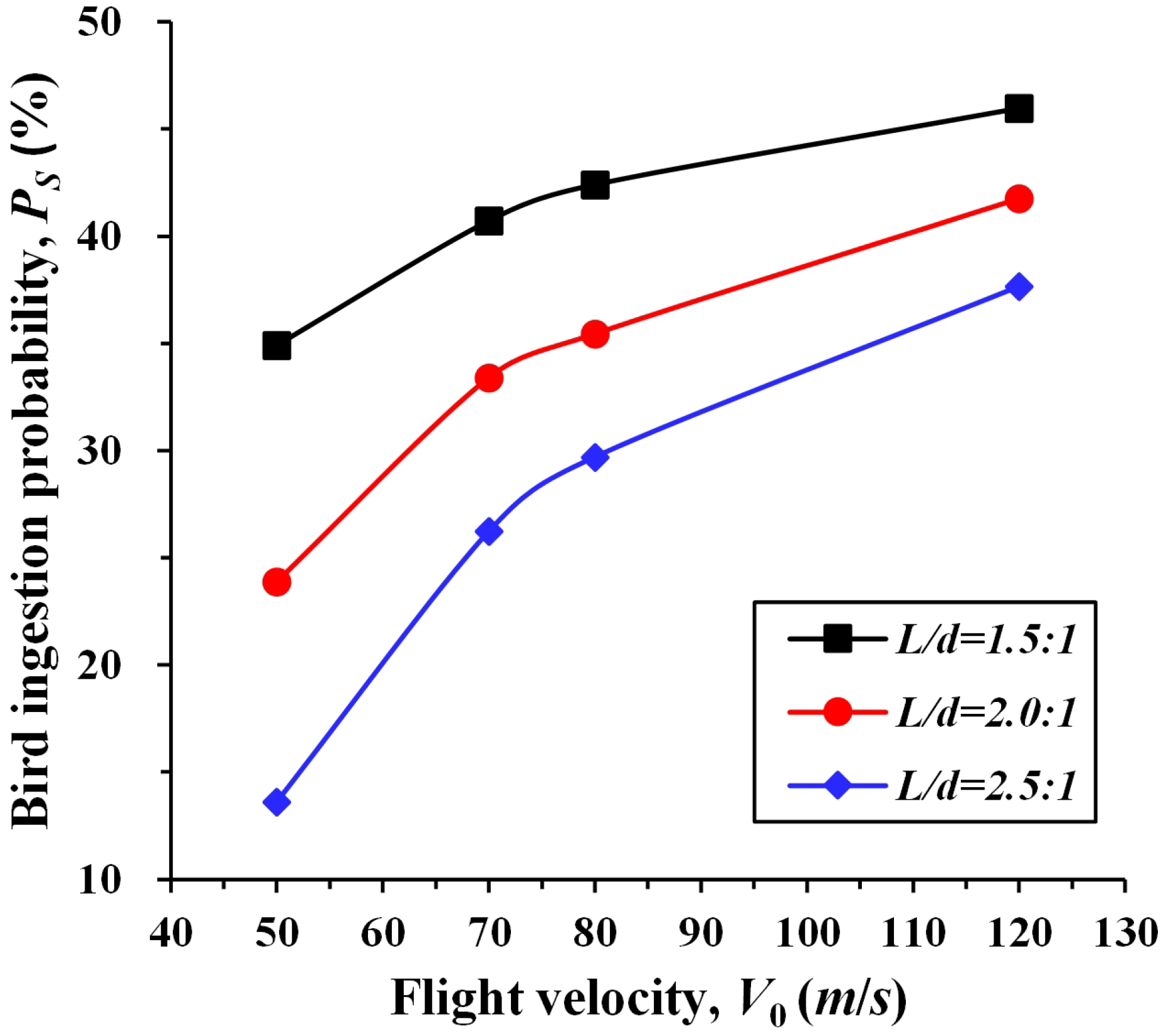
4. Application to bird-ingestion Probability of Turboprop Engine Intake

To further verify the proposed method, we apply it to compute the probability of bird ingestion in a turboprop engine’s air intake system. Figure 10 shows the FEA model of the propeller, including the spinner and engine air-inlet. A mesh of 3 · 10 5   e l e m e n t s is generated to obtain the initial coordinate sets of nodes on the surface of the FEA model. The propeller is given a constant angular velocity of ω = 96.34 r a d / s and the distances from the points on the blade to the propeller’s center axis range from 0.6 to 1.7 m.
The straight-ended cylinder configuration with diameter d = 0.08285 m is selected as the substituted model of a bird, which is assumed to fly vertically towards the rotation surface of the propeller blades, as shown by the arrows in Figure 10b, i.e., θ , β , α 1 , α 2 , α 3 = 0 , 0 , 0 , 90 , 90 . Denoting the minimum distances from the bird’s possible fly-in positions to the propeller center axis as r d = r d 1 , r d 2 , , apparently the propeller-crossing probability of the bird remains constant if the r d of the different flight trajectories above are equal.
To check the impact of the substituted model’s parameters on the changing trend in the propeller-crossing probability with respect to r d , four flight velocities V 0 = (50, 70, 80, 120) m/s and three aspect ratios L / d = (1.5:1, 2.0:1, 2.5:1), as well as twelve values of r d , from 0.6 to 1.7 m with an interval length of 0.1 m, are considered in our simulations. For each set of V 0 , L L d d , r d , the simulation is repeated 2500 times and the results are collected to generate the distribution plots of the propeller-crossing probability for all possible sets, as shown in Figure 11.
We randomly choose a pair of simulation conditions ( V 0 , L / d ) and maintain one variable at a constant value while varying the other, which allows a direct comparison of the influence of each variable on the propeller-crossing probability tendency, as shown in Figure 12.
As can be seen, with an increase in r d (indicating that the fly-in position is increasingly far away from the propeller’s center axis), the propeller-crossing probability of the bird rises. Additionally, as V 0 increases or L / d decreases, the probability also increases. However, it is worth noting that this upward trend will eventually reach a point of convergence, with the probability stabilizing at a certain value as r d continues to increase, which is inconsistent with engineering intuition. The point of convergence occurs at a larger r d for higher values of V 0 , indicating that the fly-in position is further from the propeller’s center axis. On the other hand, L / d does not appear to have a significant impact on this trend variation.
This phenomenon can be partially explained based on the idealized model presented in Section 3. By substituting Equations (A2)–(A7) into Equation (A1), the propeller-crossing probability can be derived as follows:
P R d = 1 N b 2 π · ω V 0 · L + b N b π · arcsin d + a 2 R d + N b 2 π · R d · b tan δ , C a s e 1 P R d = 1 N b 2 π · ω V 0 · L b N b π · arcsin d + a 2 R d N b 2 π · R d · b tan δ , C a s e 2
when R d , the N b N b π π · arcsin d + a d + a 2 R d 2 R d 0 and N b N b 2 π R d 2 π R d · b b tan δ tan δ 0 , thus, the P R d will eventually converge to a constant value that is determined solely by the shape parameter and movement conditions of both the propeller and the bird. The physical meaning of r d in this case is similar to that of R d in the idealized model, while the primary difference between the real case and the idealized model lies in the propeller blade structure. Nevertheless, the simulation results reveal that the trend in the propeller-crossing probability with real blades is consistent with that predicted by the idealized model. This finding provides additional evidence supporting the accuracy of the idealized model.
Suppose that the bird will be ingested into the engine intake if it crosses the propeller in front of the air-inlet. Denoting the probability of a bird-ingestion event as P S , and denote the probability of a bird crossing the propeller from a certain point as P i , it can be noted that these two probabilities are related as follows:
P S = S P i d S S d S , i S
We choose V 0 , L L d d = (120 m/s, 2.5:1) as the simulation condition for illustration, and mark the outline of the air-inlet on the probability distribution plot, as shown in Figure 13. It needs to be noted that, for ease of computation, the outline of the air-inlet is approximated as an annular-sector-shaped region, with a radius ranging from r d 4 to r d 8 and an angle of ξ . Given the flight trajectory of the bird in this case, P i can be expressed as a function with respect to r d . Therefore, the probability of bird ingestion, P S , can be obtained as
P S = 0 ξ r d 4 r d 8 r · P ( r ) d r d ξ 0 ξ r d 4 r d 8 r d r d ξ ξ · i = 4 8 1 r d i · P r d i + r d i + 1 · P r d i + 1 · ( Δ r / 2 ) ( ξ / 2 ) · r 2 r = r d 4 r = r d 8
As a result, the P S for each set of V 0 , L L d d conditions is plotted in Figure 14. It is evident that as V 0 increases or L / d decreases, P S increases and gradually converges to a constant value, similar to the trend in the propeller-crossing probability observed in Figure 12a. Since the outline of the air-inlet has limited the range of r d , which is equivalent to R d having a definite value in Equation (A1), the propeller-crossing probability approaches a stable value less than 1 as V 0 tends to infinity. This probability is solely determined by the shape parameters of both the propeller and the bird. Consequently, the P S achieved by the integration of the propeller-crossing probability will approach a stable value.

5. Conclusions

This paper proposes a novel model for evaluating the propeller-crossing probability of a flying foreign object using a simulation method. Based on the essence of object collision in space, this method determines whether the foreign object can successfully cross through the propeller by comparing the distance between the foreign object’s trajectory and the surface points of the propeller with a preset threshold value.
To achieve this, a high-fidelity element model of the propeller is utilized to obtain the real-time spatial coordinates set of its surface points. We incorporate a variety of typical foreign-object-substituted models into a new concentric-spherical model and construct the flight trajectory of the foreign object based on the model’s centroid. We take the inner and outer radius of the concentric sphere as the collision threshold and convert the spatial coordinate system to obtain a convenient computational judgment criteria. The proposed model enables us to simulate foreign objects crossing the propeller with different shapes, flight attitudes, and flying-in positions.
To validate the proposed model and simulation method, we constructed an analytical model that demonstrates its high accuracy in assessing the propeller-crossing probability, while avoiding the expensive financial, human, and time costs associated with real propeller-crossing tests. The proposed model and method are then applied to calculate the probability of bird ingestion by the engine of a turboprop aircraft, which revealed that increases in the flight speed and aspect ratio of the bird have opposite effects on the crossing probability. Additionally, the probability of bird ingestion eventually converges to a certain constant value.
Our future research will involve the exclusion performance of foreign objects for turboprop engines and provide a design optimization method based on the findings presented in this paper.

Author Contributions

Conceptualization, J.Z.; methodology, J.Z. and Y.L.; validation, K.C. and X.Y.; formal analysis, J.Z. and Z.Y.; investigation, J.Z. and Y.L.; data curation, X.Y. and Q.Z.; writing—original draft preparation: J.Z. and Y.L.; writing—review and editing: K.C., X.Y., Z.Y. and Q.Z; supervision, Z.Y. All authors have read and agreed to the published version of the manuscript.

Funding

This research was funded by the Civil Airplane Technology Development Program (MJ-2020-F-10).

Institutional Review Board Statement

Not applicable.

Informed Consent Statement

Not applicable.

Data Availability Statement

The data for this study is available upon request from the corresponding author.

Conflicts of Interest

The authors declare no conflict of interest.

Appendix A. Derivation of the Crossing Probability for Analytical Models

Since the crossing event has the potential to occur at any point on the surface of the propeller and R d represents the variable crossing position, the propeller-crossing probability at a certain R d can be determined as follows:
P R d = L A r c L C = L A r c 2 π · R d , L A r c > 0
where L C denotes the circumference of the circle with radius R d , while L A r c denotes the cumulative length of all the gap arcs on this circle. These arcs comprise fly-in points from which the foreign object may cross the propeller successfully.
Assuming the propeller blade remains stationary relative to the foreign object, the foreign object will possess a velocity of equal magnitude, but in the opposite direction to that of the blade motion, as shown in Figure A1.
Figure A1. Propeller crossing sketch (taking straight - ended cylinder configuration as an example).
Aerospace 10 00925 g0a1
The trajectory of the foreign object centroid is illustrated as a solid red line with black dots at both ends, and the angle ϑ between the trajectory and the foreign object velocity vector V 0 will depend on the values of V 0 and ω · R d . Hence,
tan ϑ = ω · R d V 0
Lines l 1 and l 2 are constructed parallel to the trajectory and intersecting with the leading and trailing blade, respectively, within the range of L 1 , indicated by the blue dashed lines. In cases where each parallel line and its intersecting blade have only one point of intersection, the corresponding intersection points could be { K 1 , K 4 } or { K 2 , K 3 } , where { K 1 , K 2 } and { K 3 , K 4 } correspond to the front and rear vertices of the leading and trailing blade, respectively, all within the range of L 1 .
The foreign object’s fly-in positions with respect to l 1 and l 2 determine the boundaries of the arc length O 2 L O 2 R , within which the foreign object can pass through the propeller unobstructed, and we have
O 2 L O 2 R = L A r c L A r c N b N b L 1 = L C L C N b N b
The propeller-crossing process can be classified into two scenarios based on the geometric configuration of the foreign object substitute models, as observed from the top view. The type of edges in these configurations, whether they are straight or curved, is a key determinant in establishing the fly-in boundaries for successful traversal, as shown in Figure. Meanwhile, let P 1 and P 2 denote the intersection points of l 1 and l 2 with the motion trajectory of the propeller blades’ front margin, respectively, these intersections may coincide with a certain vertex of the blades depending on the magnitude of π / 2 δ and θ .
Figure A2. Schematic illustration of the geometric relationship for propeller - crossing boundaries. (a,b) represent the geometric configuration of foreign object substitute models with straight edges from the top view, while (c,d) denote those with curved edges (taking sphere configuration as an example).
Aerospace 10 00925 g0a2aAerospace 10 00925 g0a2bAerospace 10 00925 g0a2c
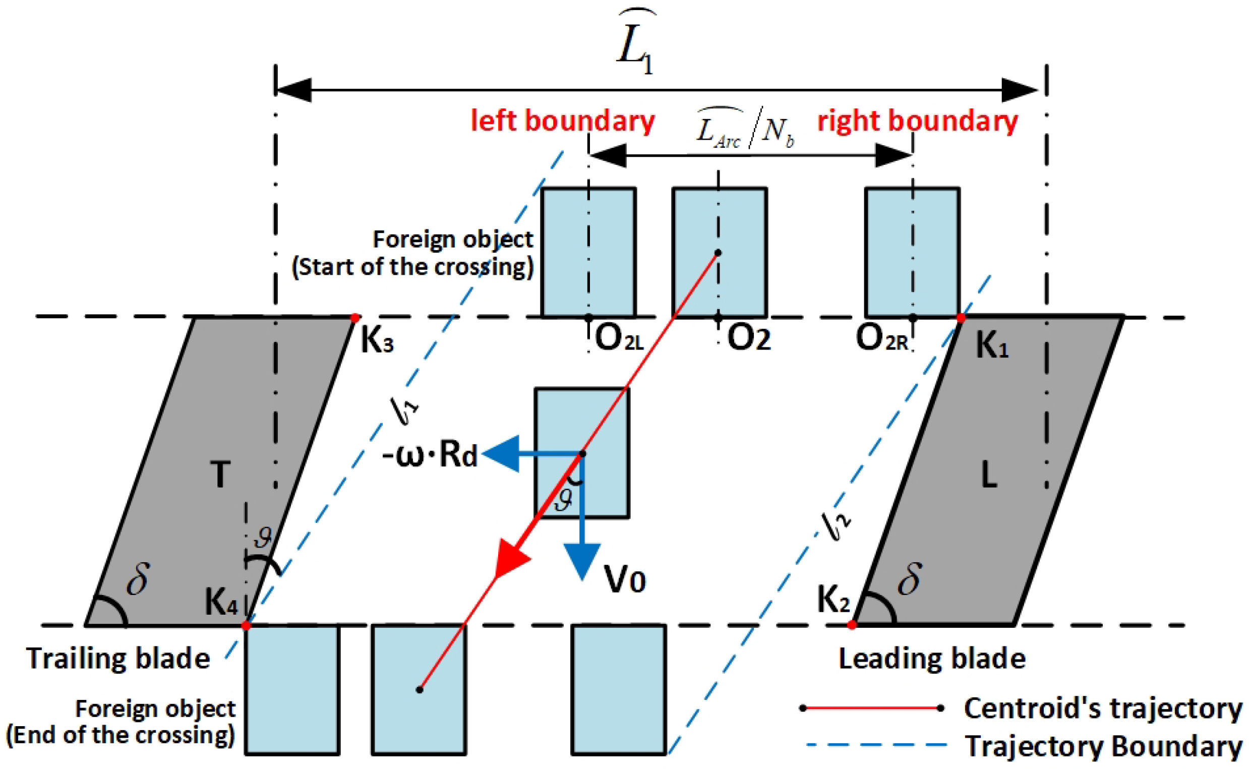
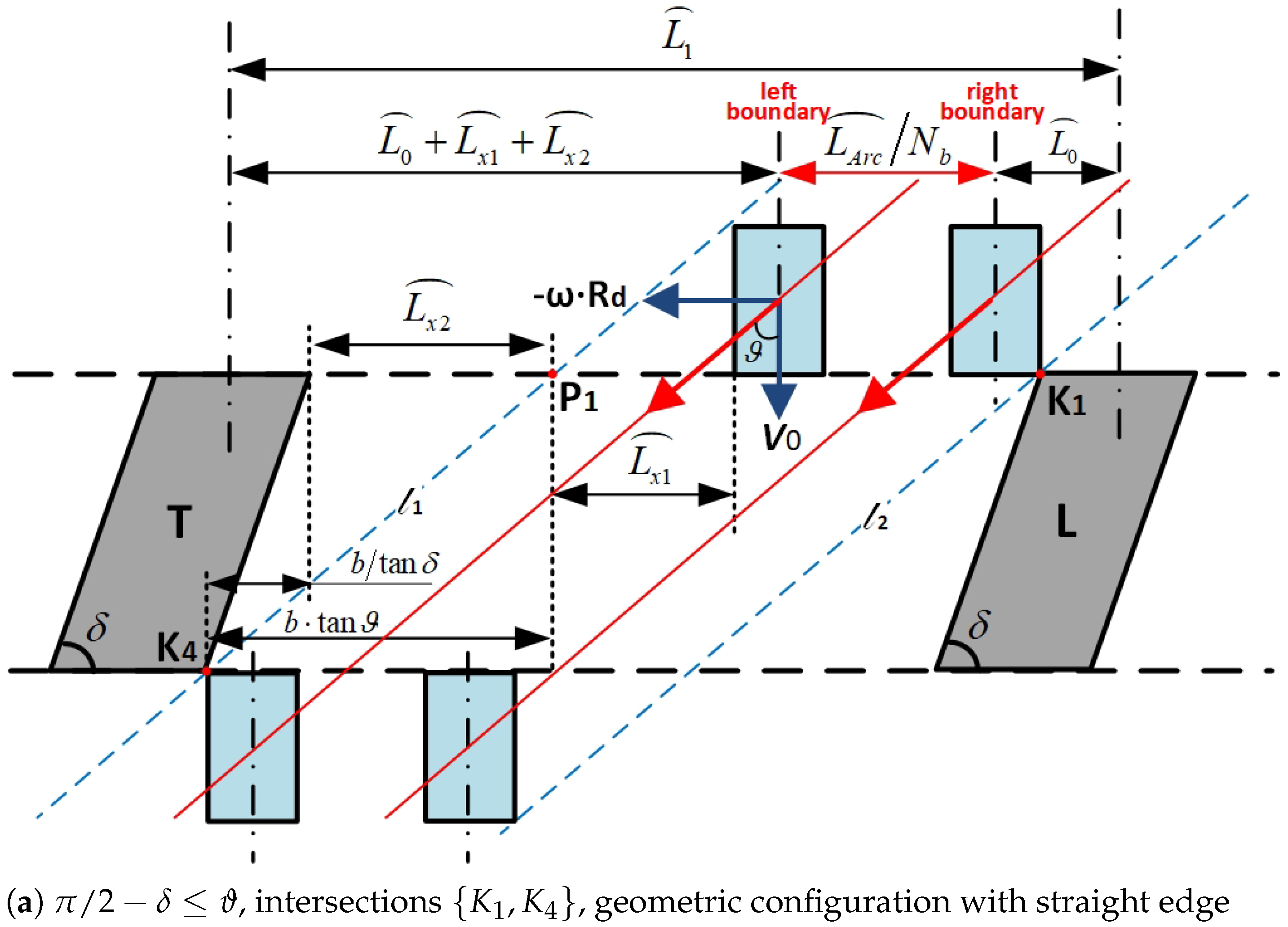
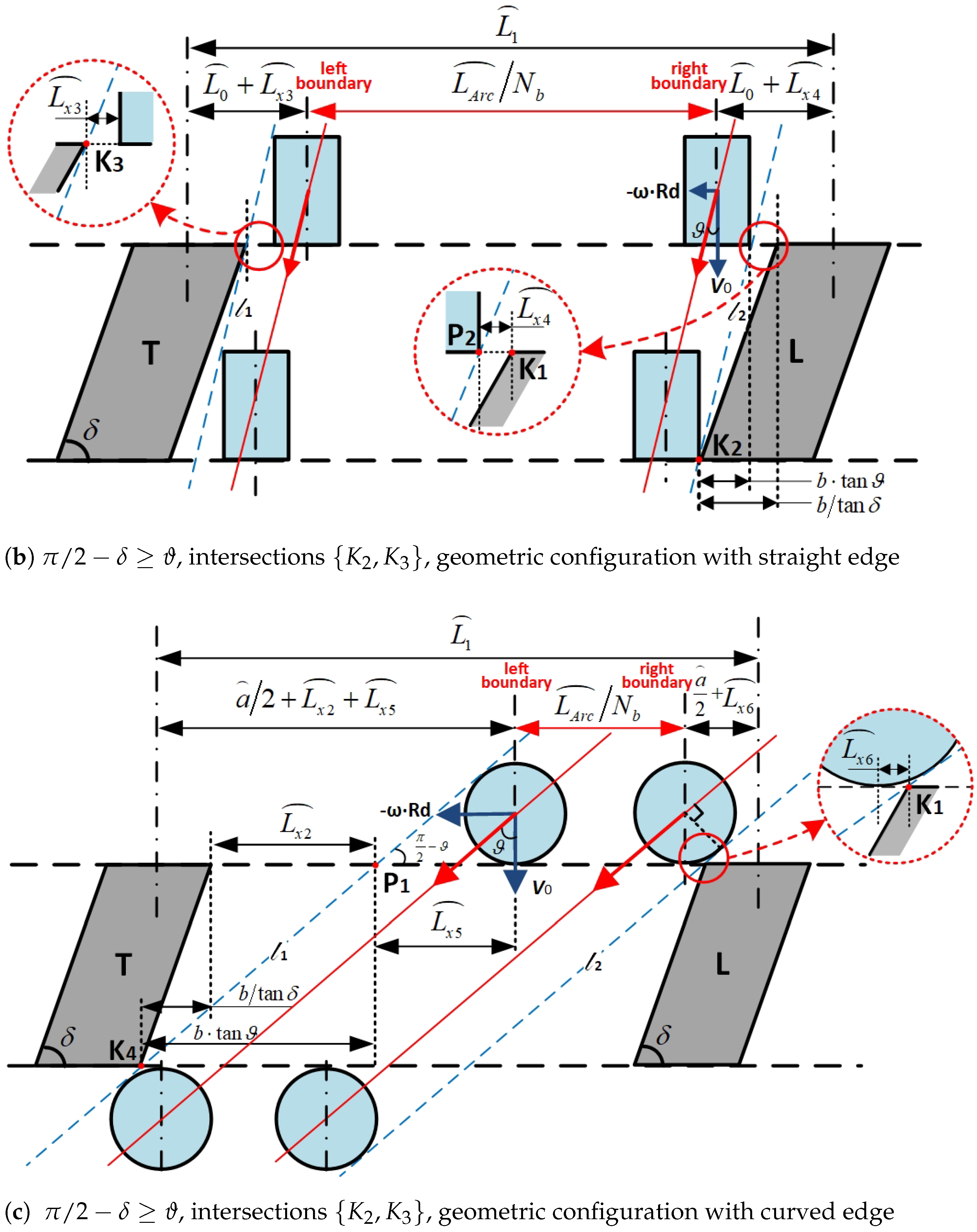
  • Scenario 1: Substitute Models With Straight Edges From the Top View
Foreign object substitution models of the straight-ended cylinder and rectangular configurations can be visualized as rectangles with straight edges in the top view. In such a scenario, there are two possible cases for the propeller-crossing boundaries based on the relationship between π / 2 δ and θ .
Case 1: When π π 2 2 δ ϑ , the intersection points of parallel lines and blades would be { K 1 , K 4 } , P 2 coincides with vertex K 1 of the leading blade, and the corresponding geometric relationship of the propeller-crossing boundary is shown in Figure a. Consequently, the propeller-crossing boundaries for case 1 in scenario 1 have the following relationship:
L A r c L A r c N b N b = L 1 2 L 0 + L x 1 + L x 2
where L x 1 and L x 2 denote the minimum distances between point P 1 to its closest edge of the foreign object and the trailing blade, respectively.
Case 2: When π π 2 2 δ ϑ , the intersection points of parallel lines and blades would be { K 2 , K 3 } , P 1 coincides with vertex K 3 of the trailing blade, and the corresponding geometric relationship of the propeller-crossing boundary is depicted in Figure b. Hence, the propeller-crossing boundaries for case 2 in scenario 1 have the following relationship:
L A r c L A r c N b N b = L 1 2 L 0 + L x 3 + L x 4
where L x 3 and L x 4 denote the minimum distances between point { K 2 , K 3 } to their closest edges of the foreign object, respectively.
Detailed expressions for each item in Equations (A4) and (A5) are listed in Table A1. Therefore, the propeller-crossing probability at a given value of R d can be calculated by substituting the relevant shape parameters of the foreign object and propeller blade into Equations (A4), (A5), and (A1).
Table A1. Details of propeller-crossing probability items in scenario 1.
ExpressionConfigurationStraight-Ended
Cylinder
Rectangular
Cases and Items
Common L 1 2 π · R d 2 π · R d N b N b
L 2 R d · arcsin d + a 2 R d R d · arcsin a 2 R d Δ z 2 + Δ y 2 + arctan Δ y 2 R d Δ z
Case1 L x 1 h · tan ϑ Δ x · tan ϑ
L x 2 b · tan ϑ 1 1 tan δ tan δ
Case2 L x 3 h · tan ϑ Δ x · tan ϑ
L x 4 b · 1 1 tan δ tan δ tan ϑ
  • Scenario 2: Substitute Models With Curved Edges From the Top View
Foreign object substitution models of sphere, ellipsoid, and hemispherical-ended cylinder configurations can be visualized as geometric shapes with curved edges in the top view, such as circles, ellipses, etc. Similarly, there are also two possible cases for the propeller-crossing boundaries, and we take the sphere configuration as an example.
Case 1: When π π 2 2 δ ϑ , the intersection points of parallel lines and blades would be { K 1 , K 4 } , P 2 coincides with vertex K 1 of the leading blade, and the corresponding geometric relationship of the propeller-crossing boundary is plotted in Figure c. The propeller-crossing boundaries for case 1 in scenario 2 are calculated as follows:
L A r c L A r c N b N b = L 1 a + L x 2 + L x 5 + L x 6
where L x 5 denotes the minimum distance between P 1 to the central axis of the foreign object which is tangent to l 1 , while L x 6 denotes the minimum distance between K 1 to the central axis of the foreign object tangent to l 2 .
Case 2: When π π 2 2 δ ϑ , the intersection points of parallel lines and blades would be { K 2 , K 3 } , P 1 coincides with vertex K 3 of the trailing blade, and the corresponding geometric relationship of the propeller-crossing boundary is depicted in Figure d, The propeller-crossing boundaries for case 2 in scenario 2 are obtained as follows:
L A r c L A r c N b N b = L 1 a + L x 5 + L x 7 + L x 8
where L x 7 and L x 8 denote the minimum distances between P 2 to the leading blade vertex ( K 1 ) and to the central axis of the foreign object which is tangent to l 1 , respectively.
Detailed expressions for each item of Equations (A6) and (A7) are listed in Table A2. As a result, the propeller-crossing probability at a given value of R d can be calculated by substituting the relevant shape parameters of the foreign object and propeller blade into Equations (A6), (A7), and (A1).
Table A2. Details of propeller-crossing probability items in scenario 2.
Expression ConfigurationSphereHemispherical-Ended
Cylinder
Ellipsoid
Cases and Items
Common a 2 R d arcsin a 2 R d
L 5 d 2 · tan π π 4 4 ϑ ϑ 2 2 d 2 + h + d 2 sin ϑ · tan ϑ h 2 · tan ϑ + 1 2 · u 1 h · tan ϑ 2 + u d 2 1 2
Case1 L x 2 b · tan ϑ 1 tan δ
L x 6 d 2 · tan π π 4 4 ϑ ϑ 2 2 d 2 · tan π π 4 4 ϑ ϑ 2 2 h 2 · tan ϑ 1 2 · u 1 h · tan ϑ 2 + u d 2 1 2
Case2 L x 7 b · 1 tan δ tan ϑ
L x 8 d 2 · tan π π 4 4 ϑ ϑ 2 2 d 2 · tan π π 4 4 ϑ ϑ 2 2 h 2 · tan ϑ 1 2 · u 1 h · tan ϑ 2 + u d 2 1 2
where u = d 2 ( h · tan ϑ ) 2 + d 2 .

References

  1. Böhm, H.; Högner, L.; Meyer, M.; Mailach, R.; Hornig, A.; Gude, M. A Methodology for a Coupled Structural–Computational Fluid Dynamics Analysis of Compressor Rotor Blades Subjected to Ice Impact With Uncertain Impactor Parameters. J. Eng. Gas Turbines Power 2023, 145, 031001. [Google Scholar] [CrossRef]
  2. Yang, Q.; Guo, X.; Dong, W.; Wang, A. Ice Accretion and Aerodynamic Effects on a Turbofan Engine Nacelle under Takeoff Conditions. Aerosp. Sci. Technol. 2022, 126, 107571. [Google Scholar] [CrossRef]
  3. Dolbeer, R.A.; Begier, M.J.; Miller, P.R.; Weller, J.R.; Anderson, A.L. Wildlife Strikes to Civil Aircraft in the United States, 1990–2019. Technical Report DOT/FAA/TC-21/19; United States Department of Transportation; Federal Aviation Administration; William J. Hughes Technical Center: Atlantic City, NJ, USA, 2021. [Google Scholar]
  4. Juračka, J.; Chlebek, J.; Hodaň, V. Bird Strike as a Threat to Aviation Safety. Transp. Res. Procedia 2021, 59, 281–291. [Google Scholar] [CrossRef]
  5. Bojdo, N.; Filippone, A.; Parkes, B.; Clarkson, R. Aircraft Engine Dust Ingestion Following Sand Storms. Aerosp. Sci. Technol. 2020, 106, 106072. [Google Scholar] [CrossRef]
  6. Liu, H.; Che Man, M.H.; Low, K.H. UAV Airborne Collision to Manned Aircraft Engine: Damage of Fan Blades and Resultant Thrust Loss. Aerosp. Sci. Technol. 2021, 113, 106645. [Google Scholar] [CrossRef]
  7. Pepi, M.; Squillacioti, R.; Pfledderer, L.; Phelps, A. Solid Particle Erosion Testing of Helicopter Rotor Blade Materials. J. Fail. Anal. Prev. 2012, 12, 96–108. [Google Scholar] [CrossRef]
  8. Smith, J.G.; Wohl, C.J.; Palacios, J.L.; Connelly, B.D.; Culver, G.F.; Torchia, P.J.; Chauby, M.J.; Denkins, M.H.; Beck, D.M. Impact Ice Adhesion Strength of Stainless Steel 304 as Determined on a Centrifuge Test Stand. Cold Reg. Sci. Technol. 2022, 196, 103492. [Google Scholar] [CrossRef]
  9. Tan, J.F.; Yon, T.; He, L.; Yu, L.J.; Wang, C. Accelerated Method of Helicopter Brownout with Particle-Particle Collisions. Aerosp. Sci. Technol. 2022, 124, 107511. [Google Scholar] [CrossRef]
  10. Li, J.; Lou, Y.; Chai, X.; Ma, Z.; Jin, X. Numerical Simulation of Bird Strike on Jet Engine Considering Bird Ingestion Requirements. J. Aircraft 2022, 59, 761–773. [Google Scholar] [CrossRef]
  11. Guo, J.; Zuo, H.; Zhong, Z.; Jiang, H. Foreign Object Monitoring Method in Aero-Engines Based on Electrostatic Sensor. Aerosp. Sci. Technol. 2022, 123, 107489. [Google Scholar] [CrossRef]
  12. Cai, J.; Bao, H.; Zuo, H.; Huang, Y. Safety Evaluation of Airworthiness Requirement of Bird-Strike on Aeroplane. Eng. Fail. Anal. 2019, 102, 407–416. [Google Scholar] [CrossRef]
  13. US Department of Transportation. CFR14 Part 33: Airworthiness Standards: Aircraft Engines; Federal Aviation Administration: Washington, DC, USA, 2015.
  14. Long, S.; Mu, X.; Liu, Y.; Wang, H.; Zhang, X.; Yao, X. Failure Modeling of Composite Wing Leading Edge under Bird Strike. Compos. Struct. 2021, 255, 113005. [Google Scholar] [CrossRef]
  15. Luo, G.; Xu, Z.; Shen, H.; Chen, W.; Zhang, H. Experimental Study on the Impact Load of Internally Supported Gelatin Bird Projectiles. Eng. Fail. Anal. 2021, 124, 105336. [Google Scholar] [CrossRef]
  16. Liu, L.; Shao, H.; Zhu, X.; Zhao, Z.; Zhang, G.; Luo, G.; Chen, W. Bird Impact Response and Damage Mechanism of 3D Orthogonal Woven Composite Aeroengine Blades. Compos. Struct. 2023, 304, 116311. [Google Scholar] [CrossRef]
  17. Zhou, Y.; Sun, Y.; Cai, W. Bird-Striking Damage of Rotating Laminates Using SPH-CDM Method. Aerosp. Sci. Technol. 2019, 84, 265–272. [Google Scholar] [CrossRef]
  18. Yupu, G.; Zhenhua, Z.; Wei, C.; Deping, G. Foreign Object Damage to Fan Rotor Blades of Aeroengine Part I: Experimental Study of Bird Impact. Chin. J. Aeronaut. 2007, 20, 408–414. [Google Scholar] [CrossRef]
  19. Yupu, G.; Zhenhua, Z.; Wei, C.; Deping, G. Foreign Object Damage to Fan Rotor Blades of Aeroengine Part II: Numerical Simulation of Bird Impact. Chin. J. Aeronaut. 2008, 21, 328–334. [Google Scholar] [CrossRef]
  20. Zhou, J.; Liu, J.; Zhang, X.; Yan, Y.; Jiang, L.; Mohagheghian, I.; Dear, J.P.; Charalambides, M.N. Experimental and Numerical Investigation of High Velocity Soft Impact Loading on Aircraft Materials. Aerosp. Sci. Technol. 2019, 90, 44–58. [Google Scholar] [CrossRef]
  21. Guida, M.; Marulo, F.; Belkhelfa, F.Z.; Russo, P. A Review of the Bird Impact Process and Validation of the SPH Impact Model for Aircraft Structures. Prog. Aerosp. Sci. 2022, 129, 100787. [Google Scholar] [CrossRef]
  22. Ruiz-Calavera, L.P.; Cid-Arroyo, S.; Benitez-Montañes, L. Spinner Shed Ice Engine Ingestion Assessment Methodology. In Proceedings of the 29th Congress of the International Council of the Aeronautical Sciences, ICAS Paper. St. Petersburg, Russia, 7–12 September 2014; Volume 66, pp. 1–10. [Google Scholar]
  23. Metz, I.C.; Ellerbroek, J.; Mühlhausen, T.; Kügler, D.; Hoekstra, J.M. Analysis of Risk-Based Operational Bird Strike Prevention. Aerospace 2021, 8, 32. [Google Scholar] [CrossRef]
  24. Panpan, J.; Taofeng, H.; Qi, H.; Yiqian, D.; Liming, W. Method for Evaluating Probability of Collision of Flying Birds With Wind Shield Over Oar. CN Patent CN108090257B, 4 May 2021. [Google Scholar]
  25. Wang, K.; Huang, H.x.; Liu, L.; Zheng, G.j.; Lin, Z.k.; Sun, S.; Tan, H.j. A New Distortion Evaluation Method Based on Geometric Association for Arbitrary Cross-Sectional Shape of Inlet. Aerosp. Sci. Technol. 2022, 128, 107728. [Google Scholar] [CrossRef]
  26. Xu, K.; Zha, G. System Energy Benefit Using Co-Flow Jet Active Separation Control for a Serpentine Duct. Aerosp. Sci. Technol. 2022, 128, 107746. [Google Scholar] [CrossRef]
  27. Mi, B.; Zhan, H. Numerical Simulation on Rigid Foreign Object Exclusion in the Turboprop Engine Intake System With a Bypass Duct. IEEE Access 2019, 7, 61920–61933. [Google Scholar] [CrossRef]
  28. Masden, E.; Cook, A. Avian Collision Risk Models for Wind Energy Impact Assessments. Environ. Impact Assess. Rev. 2016, 56, 43–49. [Google Scholar] [CrossRef]
  29. Tucker, V.A. A Mathematical Model of Bird Collisions With Wind Turbine Rotors. J. Sol. Energy Eng. 1996, 118, 253–262. [Google Scholar] [CrossRef]
  30. Johnston, A.; Cook, A.S.C.P.; Wright, L.J.; Humphreys, E.M.; Burton, N.H.K. Modelling Flight Heights of Marine Birds to More Accurately Assess Collision Risk with Offshore Wind Turbines. J. Appl. Ecol. 2014, 51, 31–41. [Google Scholar] [CrossRef]
  31. Bolker, E.D.; Hatch, J.J.; Zara, C. Modeling How Windfarm Geometry Affects Bird Mortality. arXiv 2014, arXiv:1408.1580. [Google Scholar]
  32. Podolsky, R. Method of and Article of Manufacture for Determining Probability of Avian Collision. U.S. Patent US7315799B1, 1 January 2008. [Google Scholar]
  33. Holmstrom, L.A.; Hamer, T.E.; Colclazier, E.M.; Denis, N.; Verschuyl, J.P.; Ruché, D. Assessing Avian-Wind Turbine Collision Risk: An Approach Angle Dependent Model. Wind. Eng. 2011, 35, 289–312. [Google Scholar] [CrossRef]
  34. Han, C.; Gu, Y.; Sun, X.; Liu, S. Rapid Algorithm for Covariance Ellipsoid Model Based Collision Warning of Space Objects. Aerosp. Sci. Technol. 2021, 117, 106960. [Google Scholar] [CrossRef]
  35. Meguid, S.A.; Mao, R.H.; Ng, T.Y. FE Analysis of Geometry Effects of an Artificial Bird Striking an Aeroengine Fan Blade. Int. J. Impact Eng. 2008, 35, 487–498. [Google Scholar] [CrossRef]
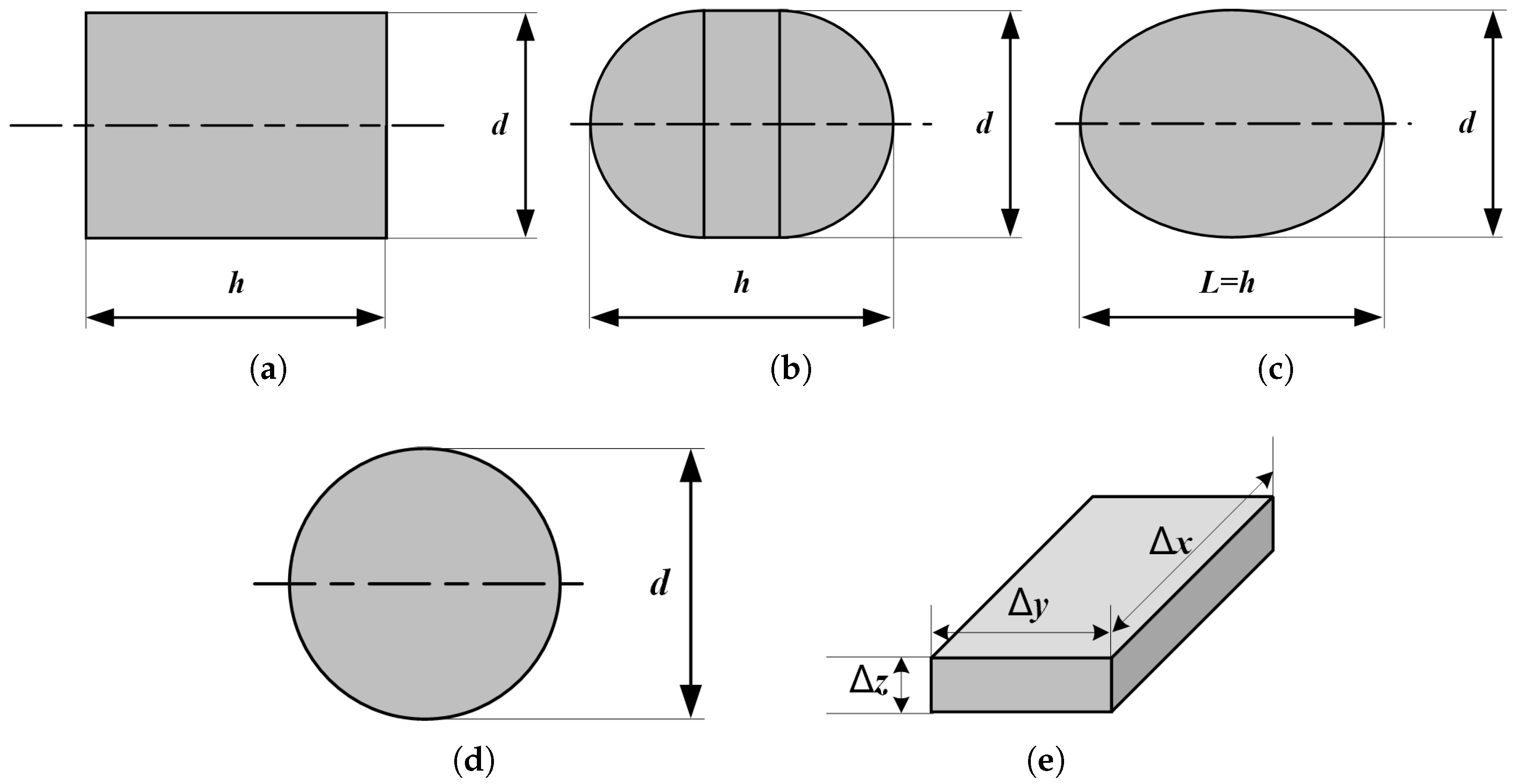
Figure 1. The schematic of foreign object crossing the propeller and ingested by the engine.
Aerospace 10 00925 g001
Figure 2. Schematic of the propeller coordinate and discretization result. (a) The origin of the coordinate system. (b) The point clouds generated by the mesh on the surface of the propeller FEA model.
Aerospace 10 00925 g002
Figure 3. The five model configurations considered for foreign objects: (a) straight-ended cylinder model of a bird, (b) hemispherical-ended cylinder model of a bird, (c) ellipsoid model of a bird, (d) spherical model of hail and dust, and (e) rectangular model of an ice slab.
Aerospace 10 00925 g003
Figure 4. Concentric-spherical model for the typical foreign object configurations: (a) straight-ended cylinder, (b) hemispherical-ended cylinder, (c) ellipsoid, (d) sphere, and (e) rectangular.
Aerospace 10 00925 g004
Figure 5. Diagrams of (a) the propeller-crossing process, and (b) the description of foreign object attitude angles (take the straight-ended cylinder configuration substituted model as an example).
Aerospace 10 00925 g005
Figure 6. Schematic diagram of coordinate system transformed according to flight trajectory. (a) Coordinate system (xyz); (b) coordinate system ( x y z ).
Aerospace 10 00925 g006
Figure 7. Schematic diagram of coordinate system transformed according to attitude angles (using straight-ended cylinder model as an example). (a) Coordinate system ( x y z ); (b) coordinate system ( x T y T z T ); (c) coordinate system ( x y z ).
Aerospace 10 00925 g007
Figure 8. Schematic diagram of the kinematic and geometric relationships during the crossing process from (a) 3D view, (b) front view, and (c) top view, taking straight-ended cylinder configuration as an example.
Aerospace 10 00925 g008
Figure 9. Scatterplots of comparison between simulation and analytical solutions of the propeller-crossing probability for typical foreign object configurations: (a) straight-ended cylinder, and (b) rectangular in scenario 1; (c) sphere, (d) hemispherical-ended cylinder, and (e) ellipsoid in scenario 2.
Aerospace 10 00925 g009
Figure 10. FEA model of propeller blades, spinner, and air-inlet section from (a) the front view, and (b) the lateral view.
Aerospace 10 00925 g010
Figure 11. Distribution plot of propeller-crossing probability with respect to r d . Given the aspect ratio (a) L / d = 1.5 : 1 , (b) L / d = 2.0 : 1 , and (c) L / d = 2.5 : 1 , with corresponding flight velocity V 0 = ( 50 , 70 , 80 , 120 ) m/s, respectively.
Aerospace 10 00925 g011
Figure 12. Comparison of the influence of substituted model’s parameters on the tendency of the propeller-crossing probability with respect to r d . (a) Aspect ratio L / d = 2.0:1, flight velocity V 0 = ( 50 , 70 , 80 , 120 ) m/s. (b) V 0 = 70 m/s, L / d = (1.5:1, 2.0:1, 2.5:1).
Aerospace 10 00925 g012
Figure 13. Schematic of bird-ingestion probability calculation using approximated air-inlet with simulation condition of ( V 0 , L / d ) = ( 70 m/s, 2.0:1).
Aerospace 10 00925 g013
Figure 14. Bird-ingestion probability with respect to the flight velocity V 0 and the aspect ratio L / d .
Aerospace 10 00925 g014
Table 1. Geometrical parameters of concentric-spherical model transformed by typical foreign object configuration.
Typical Foreign Object ConfigurationConfiguration ParametersRadius of the Inscribed Sphere (r)Radius of the Circumscribed Sphere (R)
Straight-ended cylinder h , d min { h / 2 , d / 2 } h 2 + d 2 h 2 + d 2 2 2
Hemispherical-ended cylinder h , d d / 2 ( h + d )/2
Ellipsoid h , d min { h / 2 , d / 2 } max { h / 2 , d / 2 }
Sphered d / 2 d / 2
Rectangular Δ x , Δ y , Δ z min { Δ x , Δ y , Δ z } Δ x 2 + Δ y 2 + Δ z 2 Δ x 2 + Δ y 2 + Δ z 2 2 2
Table 2. Refined criteria for propeller crossing according to object configuration.
CriterionTypical Foreign Object ConfigurationConfiguration ParametersDescription of the Refined Criterion
L 31 Straight-ended cylinder h , d d x < h 2 & d y 2 + d z 2 < d 2
L 32 Ellipsoid h , d h 2 2 d x 2 + d 2 2 d y 2 + d z 2 < 1
L 33 Rectangular Δ x, Δ y, Δ z d x < Δ x 2 & d y < Δ y 2 & d z < Δ z 2
L 34 Hemispherical-ended cylinder h , d d x < h 2 & d y 2 + d z 2 < d 2 d x > h 2 & Λ 1 o r Λ 2 *
* Λ 1 : x C n x K n h h 2 2 2 + d y 2 + d z 2 < d / 2 ; Λ 2 : x C n x K n + h h 2 2 2 + d y 2 + d z 2 < d / 2 .
Table 3. Shape parameters of typical foreign objects.
Configuration TypeShape Parameters (m)
Straight-ended cylinder L = 0.166 , d = 0.083
Rectangular Δ x = 0.166 , Δ y = 0.084 , Δ z = 0.013
Sphered = 0.085
Hemispherical-ended cylinderh = 0.083, d = 0.083
Ellipsoidh = 0.166, d = 0.083
Disclaimer/Publisher’s Note: The statements, opinions and data contained in all publications are solely those of the individual author(s) and contributor(s) and not of MDPI and/or the editor(s). MDPI and/or the editor(s) disclaim responsibility for any injury to people or property resulting from any ideas, methods, instructions or products referred to in the content.

