Article

Nonlinear Rigid-Elastic Coupled Modeling and Oscillation Mechanism Analysis of Rotor-Body-Slung-Load System

1
College of Equipment Management and UAV Engineering, Air Force Engineering University, Xi’an 710000, China
2
National Key Laboratory of Helicopter Aeromechanics, College of Aerospace Engineering, Nanjing University of Aeronautics and Astronautics, Nanjing 210016, China
*
Author to whom correspondence should be addressed.
Aerospace 2023, 10(10), 872; https://doi.org/10.3390/aerospace10100872
Submission received: 15 July 2023 / Revised: 30 September 2023 / Accepted: 30 September 2023 / Published: 7 October 2023
(This article belongs to the Special Issue Flight Dynamics, Control & Simulation)

Abstract

:
In order to reveal the mechanism of Category II rotor-body-slung-load coupled oscillation (RBSLCO) with the frequency range of 2.5~8 Hz, a novel nonlinear rigid-elastic coupled model is presented for the helicopter and slung load system (HSLS) with explicit formulation. The slung load system model is coupled with the current rigid-elastic coupled helicopter model, considering fuselage hook point rigid-elastic coupled movements, cable stretching, and hook point force from the slung load system. The results show that carrying the heaviest load is the vital state for Category II RBSLCO. As slung load mass ratio increases, rotor-fuselage coupling becomes stronger and the oscillation frequency shifts slightly, causing a maximum of 15% reduction in stability margin. In addition, even when the load is lightweight, another form of Category II RBSLCO may appear involving fuselage bending and cable stretching. This Category II RBSLCO behaves like the vertical bouncing but is divided into a high-frequency anti-phase oscillation and a relatively low-frequency in-phase oscillation.

1. Introduction

Helicopters are widely used to operate with external slung loads due to their ability to take off and land in various environments with arbitrary-shaped loads. However, according to National Transportation Safety Board investigations [1], over 10% of helicopter accidents were related to slung load operations, indicating severe safety issues. Unstable rotor-body-slung-load coupled oscillations (RBSLCOs) are usually the cause for slung load operation accidents.
RBSLCOs refer to self-excited oscillations of the helicopter and slung load system (HSLS) during flight. There are 2 categories of RBSLCOs. Category I RBSLCO has a frequency range below 1 Hz while that of Category II RBSLCO is 2.5~8 Hz. Most efforts were devoted to Category I RBSLCO related to load swinging since the risk is obvious because a swinging heavy load may drive the helicopter to move against the pilot. However, Category II RBSLCO received little attention and its mechanism is still obscure. This is because Category II RBSLCO may not be as dangerous as Category I RBSLCO, but it causes an annoying transient vibration. However, in fact, Category II RBSLCOs have already caused several mishaps that resulted in hard landings and jettisoned loads [2]. Additionally, since Category II RBSLCOs were related to lowest-order fuselage structural modes, it could be very dangerous with respect to airframe structural damage accumulation and strength limitations [3]. Thus, more research should be carried out on Category II RBSLCO to understand its mechanism.
For Category II RBSLCO study, the mathematical model of the HSLS should be established considering the ingredients as follows.
  • Rotor dynamics: To provide more lift for the slung load, the main rotor should increase collective pitch. However, high collective pitch destabilizes rotor flap-lag coupled motion such that Category II RBSLCO stability margin reduces [4].
  • Fuselage elasticity: According to a representative medium helicopter modal frequency chart [5], helicopter lowest-order fuselage structural modes may be excited by periodic rotor hub load and time-variant hook point force in the frequency range of Category II RBSLCOs.
  • All slung load system motions: Except from load swinging motion, sling stretching and load rigid-body rotation should also be modeled because their frequencies are usually in 2.5~8 Hz, which may be related to Category II RBSLCOs.
Many HSLS models have been established based on double-rigid-body assumption, aiming at load swinging analysis [6,7,8,9,10] and stability augmentation [11,12,13], as well as other purposes like slung load aerodynamics [14], slung load flight simulation [15,16,17,18], pilot-induced slung load oscillation analysis [19], etc. However, the assumption of a double-rigid-body is not applicable for Category II RBSLCO study since rotor dynamics and fuselage elasticity are essential. Thus, there is a need to establish a rigid-elastic coupled rotor-body-slung-load system model. To achieve that goal, two crucial problems should be treated ahead.
The first problem to establish the nonlinear rigid-elastic coupled HSLS model is nonlinear rotor-fuselage couplings during slung load operations. Methods could be found in research fields of rotor-fuselage coupled analysis and vibration reduction along with rotor modeling. Bauchau [20] established a rotor-fuselage coupled model for large-angle maneuver analysis. The model considered the couplings of fuselage elastic deformations and rigid-body motions using a formulation based on the floating frame attached to an arbitrary material point. Cribbs [21] presented a model based on the mean axes floating frame, avoiding the arbitrary point selection, while Meirovitch [22] pointed out that mean axes were time-varied. To avoid the tedious task of expressing aerodynamic loads in the time-varying mean axes, a model based on quasi-coordinates was presented. However, the obtained formulation was too complicated and symbolic, making it difficult for Category II RBSLCO analysis.
The second problem is to assemble the nonlinear rotor-fuselage coupled model with HSLS. The closest research field is heavy lift helicopter (HLH) aeroservoelasticity (ASE), which requires coupled modeling of rotor dynamics, fuselage elasticity, rigid-body motions, etc. In fact, except from ASE, HLHs are faced with a more severe Category II RBSLCO problem. This is because an HLH usually has a larger and softer fuselage and a slower turning main rotor, leading to overlapped frequency ranges of fixed-frame rotor modes, lowest-order fuselage modes, cable stretching modes, and slung load rigid-body motions. For example, during the development of the CH-53K helicopter, fuselage structural modes were coupled in the system model to evaluate ASE stability during slung load operations [23,24]. However, the CH-53K engineering model considered only the one-directional inertial force from rigid-body motion to fuselage deformation such that coupled dynamics of Category II RBSLCO could not be fully reflected. Moreover, Masarati [25] developed modern aeroservoelastic state-space tools with a generalized and linearized approach for helicopter rigid-elastic modeling, making the mechanisms behind the coupled behaviors obscure, neither a good choice for Category II RBSLCO study.
Recently, Wang [26] established a nonlinear helicopter rigid-elastic coupled model based on the floating frame with explicit formulation considering all necessary rigid-elastic couplings. Two crucial problems could be well treated with the model. In addition, since the model was derived based on analytical acceleration coupling matrix production, it could easily be extended to other research fields such as Category II RBSLCO study. However, since the model was originally developed to predict HLH ASE instabilities, it should be modified to support Category II RBSLCO study. The total system becomes more complicated when the slung load system is connected to the helicopter. The motion of hook point on the helicopter is the superposition of helicopter rigid-body motion and fuselage elastic deformation. Meanwhile, the force acted on the helicopter hook is huge and time-variant, including slung load gravity, aerodynamics, and inertial force.
The objective of this paper is to analyze the mechanism of Category II RBSLCO. To achieve that goal, a nonlinear rigid-elastic coupled HSLS model should be established first. The model should consider: (1) HSLS rigid-body motion and fuselage elastic deformation couplings; (2) Rotor dynamics and rigid-elastic coupled HSLS dynamics couplings.
In order to achieve our goal, in Section 2, we modified the nonlinear rigid-elastic coupled helicopter model and developed the slung load system model. Then, they were coupled with each other to establish the HSLS model, which was validated using flight test results. In Section 3, the model was applied on a sample HLH and slung load system of 36,000 kg gross weight to understand the mechanism of Category II RBSLCO.

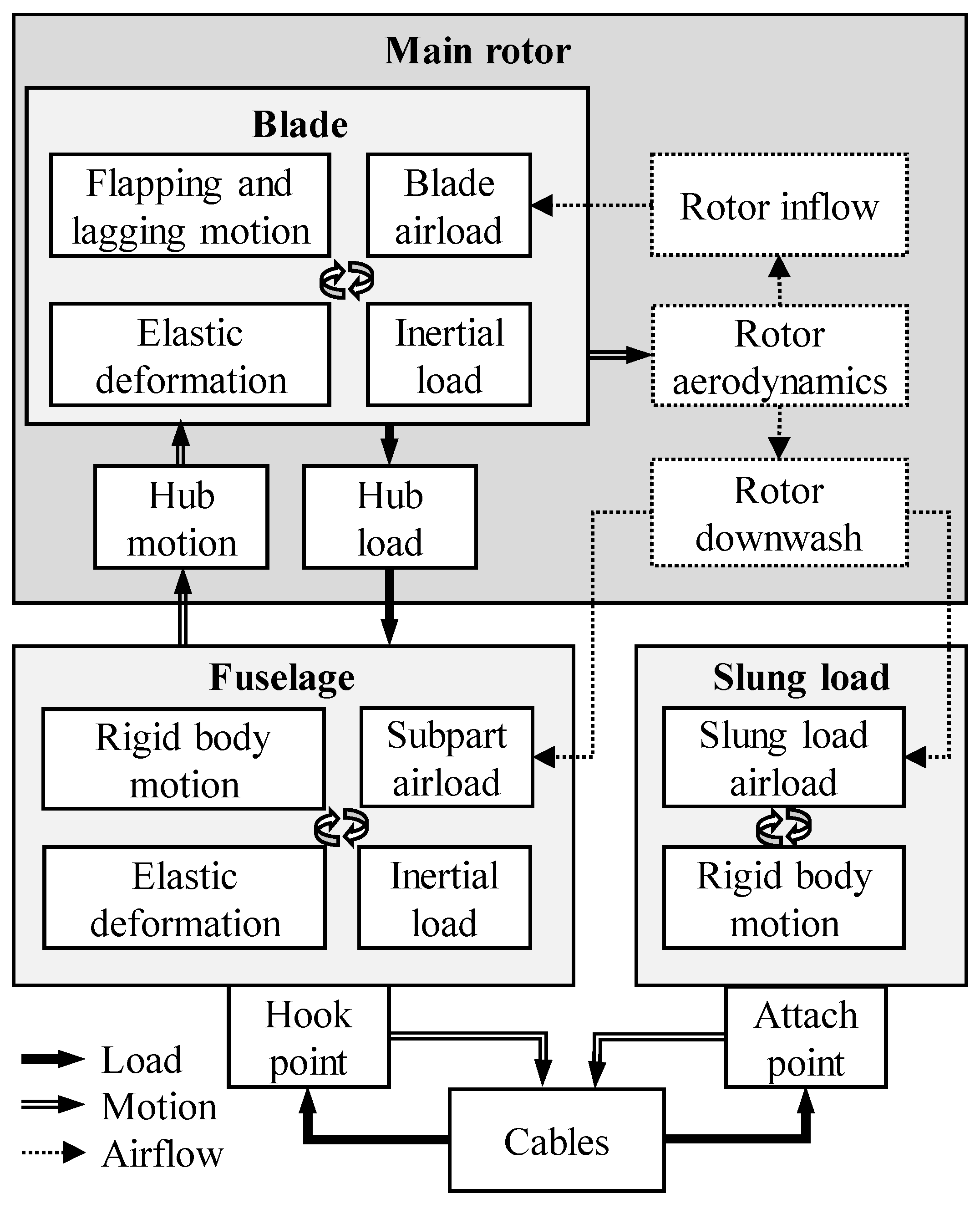
2. Nonlinear Rigid-Elastic Coupled HSLS Modeling and Validation

Figure 1 is an illustration of a heavy lift helicopter and slung load system with elastic fuselage and blades. To reveal the mechanism of Category II RBSLCO, the HSLS model should include rotor dynamics, helicopter and slung load rigid-body motions, fuselage and cable elasticity, and reflect nonlinear inertial, aerodynamic and kinematic couplings among these subsystems. Thus, the nonlinear rigid-elastic coupled modeling method was adopted to build the helicopter model in this research. Then, the slung load system model consisted of a slung load and several cables were modeled. The load was modeled as a 6 degree-of-freedom rigid body with quasi-steady nonlinear aerodynamic characteristics obtained from wind tunnel tests. Cables were modeled as linear spring damping systems. Lastly, the helicopter model and the slung load system model were assembled to form a coupled HSLS model.

2.1. Nonlinear Helicopter Rigid-Elastic Coupled Modeling

Aimed at Category II RBSLCO analysis, the helicopter model should cover a wider frequency range including rigid-body motion, low-order fuselage structural modes, and rotor modes. To achieve this goal, the nonlinear helicopter rigid-elastic coupled model developed in Ref. [26] is used. However, since slung load is suspended below the helicopter through the hook point, the helicopter model should be modified to include the contribution of hook point force. The modified external force term in helicopter Equations of Motions (EOMs) could be written in detail as:
Q _ e , F = Q _ e , V Q _ e , ω Q _ e , p F = n T ¯ F n F _ e , n n N _ e , n n + T ¯ F K F _ e , K K
in which  Q _ e , F  is divided into three parts of translation, rotation, and deformation denoted by subscripts  V ω , and  p , respectively. The notation  n  denotes the n-th subcomponent connected to the fuselage including the main rotor (1st), the tail rotor (2nd), the horizontal tail (3rd) and the vertical tail (4th).  F _ e , n n  and  N _ e , n n  denote the n-th subcomponent applied force and moment on the fuselage.  T ¯ F n  denotes the transformation matrix converting the n-th subcomponent force and the moment to fuselage generalized external force.  F _ e , K K  denotes the hook force acted on the fuselage expressed in the hook point frame, which is obtained from the slung load system.  T ¯ F K  denotes the transformation matrix converting hook force to fuselage generalized external force that could be written as:
T ¯ F K = A ¯ F K s k e w r _ K F + Ψ ¯ V , K F p _ F A ¯ F K Ψ ¯ V , K F T A ¯ F K
in which  A ¯ F K  denotes the rotation matrix from the hook point frame to body frame.  r _ K F  denotes the undeformed position vector of the hook point in body frame.  Ψ ¯ V , K F  and  Ψ ¯ ω , K F  denote the translational and rotational shape matrices at the hook point in the body frame.  p _ F  denotes the deformation generalized coordinate of the helicopter fuselage.

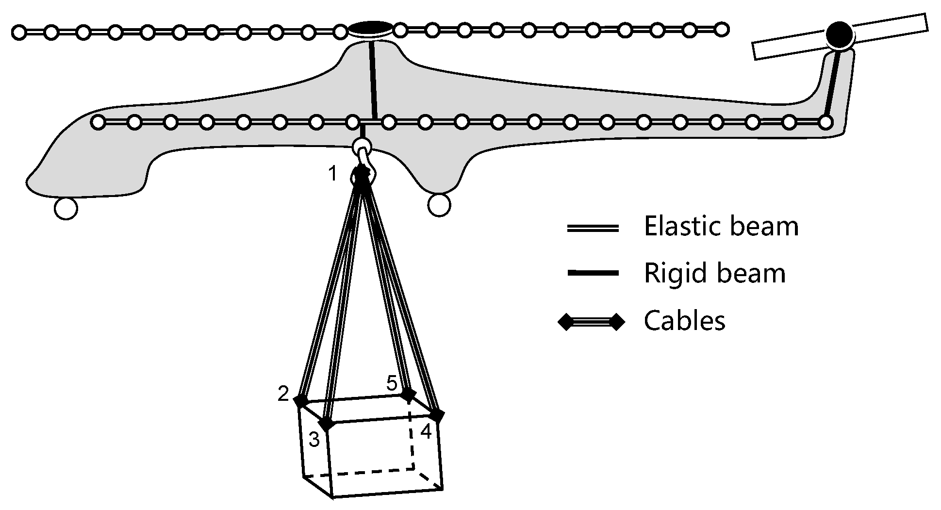
2.2. Slung Load System Modeling

The slung load system consists of a rigid-body load and several linear elastic cables. The slung load system model is based on a hook point. The position,  R _ K 0 , and velocity,  V _ K 0 , of the hook point is determined by helicopter rigid-body motions and fuselage deformation, which could be expressed as:
R _ K 0 = R _ F 0 + A ¯ 0 F r _ K F + Ψ ¯ V , K F p _ F
V _ K 0 = V _ F 0 + A ¯ 0 F ω _ F F × r _ K F + Ψ ¯ V , K F p _ F + A ¯ 0 F Ψ ¯ V , K F p _ ˙ F
in which  R _ F 0 V _ F 0 , and  ω _ F F  denotes the position, translational velocity, and rotational velocity of the helicopter, respectively.  A ¯ 0 F  denotes the rotation matrix from body frame to earth frame.  p _ ˙ F  denotes the deformation generalized velocity of fuselage.
(1)
Load Modeling
The slung load is modeled as a 6 degree-of-freedom rigid body with EOMs in slung load body frame, denoted as a superscript  L , expressed as Equation (5):
V _ ˙ L L = g _ L ω _ L L × V _ L L + F _ a e L + i F _ S i L / m L ω _ ˙ L L = I ¯ L 1 ω _ L L × I ¯ L ω _ L L + N _ a e L + i r _ S i L × F _ S i L
in which  ω _ L L  and  V _ L L  are the slung load rotational and translational velocities, while  ω _ ˙ L L  and  V _ ˙ L L  are their accelerations.  m L  and  I ¯ L  are the slung load mass and inertia moment matrix, respectively.  g _ L  is gravity vector.  F _ S i L  and  r _ S i L  denote the cable attach point force and position of the  i -th attach point on the slung load.  F _ a e L  and  N _ a e L  are the slung load aerodynamic forces and moments based on the aerodynamic coefficient interpolation tables obtained from the wind tunnel tests, which are expressed as Equation (6):
F _ a e L N _ a e L = 1 2 ρ | V _ a s L | 2 S L C _ f r c L α L , β L S L L L C _ m m t L α L , β L
in which  S L  and  L L  denote the slung load equivalent area and length.  ρ  is air density.  V _ a s L  is the slung load relative airspeed consisting of the slung load translational velocity, environment flow field, and main rotor downwash.  C _ f r c L  and  C _ m m t L  are the aerodynamic force and moment coefficients under the slung load body coordination system. They are functions of the slung load angle of attack,  α L , and sideslip angle,  β L , which are derived from  V _ a s L .
Position,  R _ S i 0 , and velocity,  V _ S i 0 , of the  i -th attach point on the slung load are obtained from the slung load motions, which could be expressed as:
R _ S i 0 = R _ L 0 + A ¯ 0 L r _ S i L
V _ S i 0 = A ¯ 0 L V _ L L + ω _ L L × r _ S i L
in which  R _ L 0  denotes the position of the slung load.  A ¯ 0 L  denotes the rotation matrix from load body frame to earth frame.
(2)
Cable Modeling
Cables are modeled as a linear spring damping system without aerodynamics. Since the damping of the cable primarily comes from material features, it is very small compared with stiffness. Cables are used to connect the hook point on the helicopter and attach point on the slung load. As is shown in Figure 1, hook point force is the result of the tensions in the four cables while attach point forces are tensions in each cable. Since both ends of the cables are connected to the helicopter hook point and slung load attach points, the relative position and velocity of the cables at both ends are obtained based on the helicopter and slung load motions, as obtained from Equations (3), (4), (7) and (8). After numbering the hook point and attach points as in Figure 1; relative position,  r _ i j , and velocity,  r _ ˙ i j , which are vectors of cables connecting  i -th and  j -th point, could be expressed as:
r _ 1 j = R _ S j 0 R _ K 0 , j = 2 ,   3 ,   4 ,   5
r _ ˙ 1 j = V _ S j 0 V _ K 0 , j = 2 ,   3 ,   4 ,   5
Tensions in the cables are calculated based on the relative position and velocity of both ends, which could be expressed as follows:
T _ i j = 0 _ , r _ i j l i j 0 r _ i j r _ i j K i j r _ i j l i j + D i j r _ ˙ i j r _ i j r _ i j , r _ i j l i j > 0
in which  T _ i j  denotes the tension vector along the cable connecting  i -th and  j -th point.  l i j K i j , and  D i j  are original length, stiffness, and damping of the cable. Hook point force in Equation (1) and cable attach point force in Equation (5) could be expressed as:
F _ e , K K = A ¯ K 0 j = 2 ,   3 ,   4 ,   5 T _ 1 j
F _ S i L = A ¯ L 0 T _ i 1
in which  A ¯ K 0  denotes the rotation matrix from the hook point frame to earth frame.  A ¯ L 0  denotes the rotation matrix from the slung load body frame to earth frame.

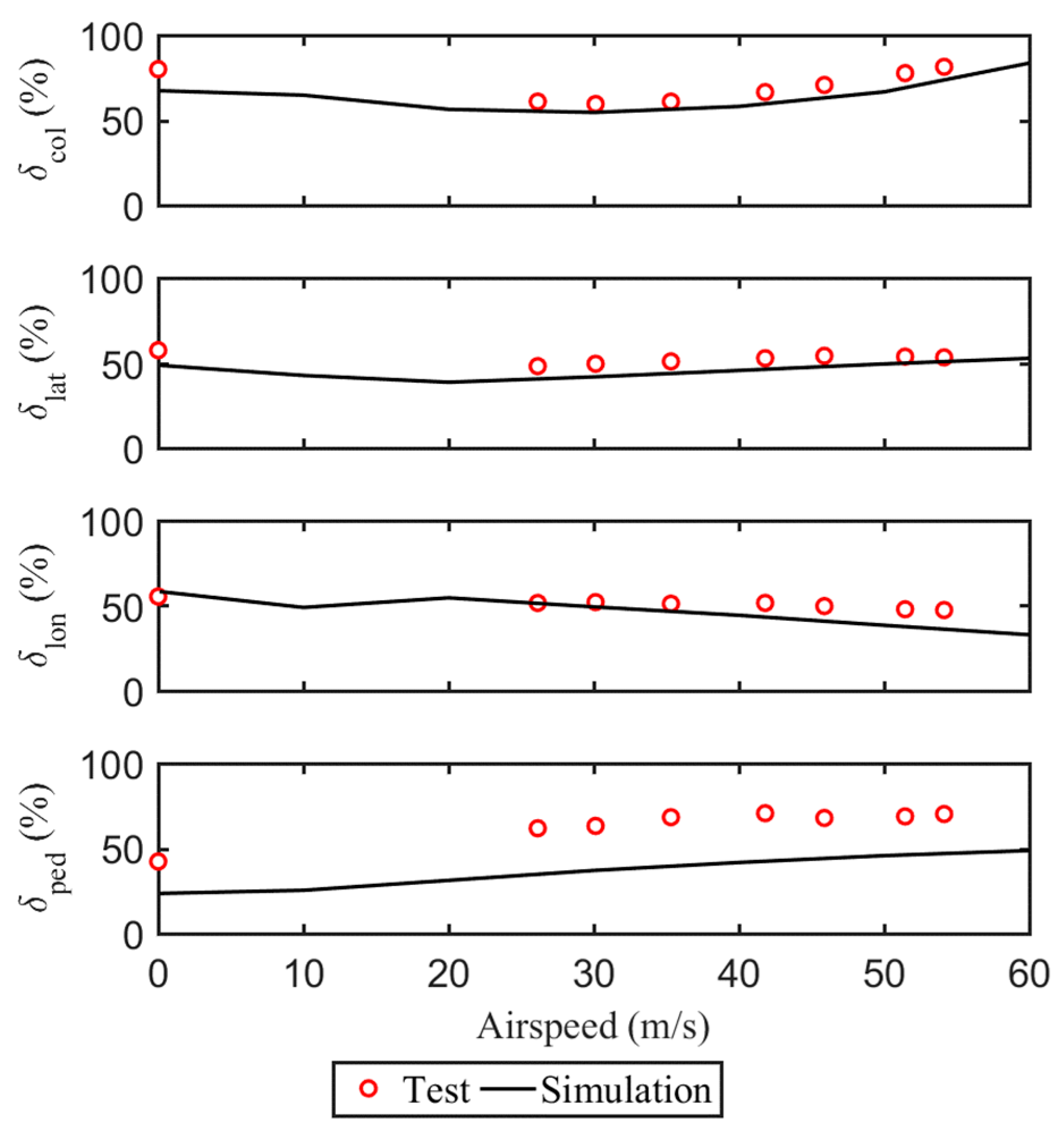
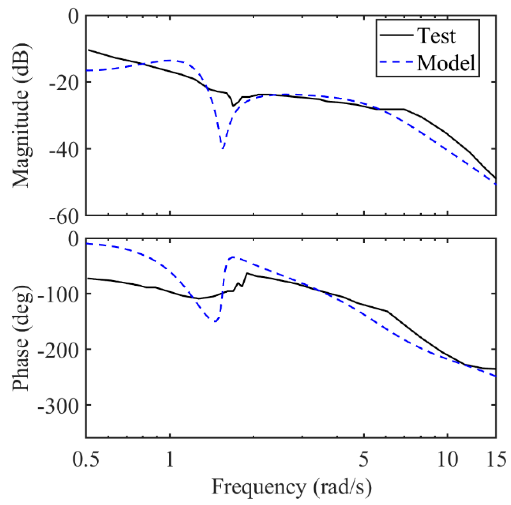
2.3. Coupled HSLS Modeling and Validation

The coupled HSLS model is established by substituting the obtained hook point force from Equation (12) to Equation (1) and cable attach point force from Equation (13) to Equation (5).
Figure 2 illustrates the couplings in HSLS. Generally, the system consists of the main rotor, fuselage, and slung load. For fuselage, the rigid-body motion, elastic deformation, subpart airloads and inertial load are all coupled. Subparts refer to the fuselage aerodynamics model, tail rotor model, empennage model, and fin model, whose motions are obtained from the superposition of the fuselage rigid-body motion and elastic deformation. Subpart airloads are calculated using the interpolation method (for fuselage aerodynamics, empennage, and fin) and rotor disk theory (for tail rotor) while subpart masses are neglected. Fuselage elastic deformation is coupled with rigid-body motion based on the floating frame theory of a deformable body, in which inertial load is considered.
The main rotor is connected to the fuselage through the hub, whose motion is the superposition of fuselage rigid-body motion and elastic deformation. Meanwhile, the main rotor hub load acting on the fuselage is affected by the main rotor motions. Thus, there is inertial coupling between the main rotor and fuselage, which is well treated by separating the acceleration matrix analytically from the rotor EOMs. Rotor blades themselves are a deformable body, whose flapping and lagging motion, elastic deformation, airloads, and inertial load are all coupled as well. Rotor blade motions are affected by the main rotor hub motions, while the hub load contains the resultant force and moment of the rotor blades, forming additional inertial coupling. The main rotor aerodynamic model is based on the Pitt–Peters dynamic inflow theory. The rotor downwash model is based on the momentum theory to calculate aerodynamic interference on fuselage subparts and the slung load.
The slung load is a rigid body with aerodynamic loads. Cables are used to connect the hook points on the fuselage and the attached points on the slung load, which have been introduced in Section 2.2 in detail.
Generally, helicopter EOMs are modified by adding the hook point force term to consider the effects of the slung load system on the helicopter. Slung load system EOMs were also derived based on a movable hook point to consider the effects of the helicopter on the slung load system. As a result, the coupled rotor-body-slung-load system was established by acting the hook force on the helicopter obtained from the slung load system and forcing the hook point of the slung load system to move according to the helicopter’s motions.
Considering the couplings in Figure 2, we obtain the EOMs of HSLS,  h _ s y s , expressed as Equation (14):
q _ ¨ s y s = h _ s y s q _ s y s , q _ ˙ s y s , δ _ s y s , t
in which  q _ s y s q _ ˙ s y s , and  q _ ¨ s y s  denote the system generalized coordinate, velocity, and acceleration vectors, respectively.  δ _ s y s  is the system control vector, including collective lever displacement,  δ c o l , control stick lateral and longitudinal displacement,  δ l a t  and  δ l o n , and pedal displacement,  δ p e d t  in Equation (14) indicates that the model is time-variant.
The UH−60A helicopter and CONEX container flight test results are used for slung load validation, including trimmed characteristics [18,27], shown in Figure 3 and Figure 4, and frequency response [16], shown in Figure 5. In general, the model’s calculated results agree well with the flight tests. However, several obvious disagreements should be explained. Figure 3 shows a constant pedal displacement deviation, which is mainly caused by the sidewind and sideslip, but the related environmental information is not given. Thus, the increase in pedal displacement for overcoming the sidewind and sideslip is not reflected in model’s results. However, the correctness of pedal displacement for a helicopter without slung load has been validated [26]. Figure 4b shows the trimmed characteristics of the trail angle,  α c , defined in Figure 4a, while  β c  and  l c  in Figure 4a are side swing angle and generalized cable length, respectively. The model’s calculated trail angle agrees well with the test results in low speed, but the agreement deteriorates in high speed. This is because slung load spinning is restricted in the model but unconstrained in real flight. In Figure 5, the model’s frequency responses agree well with the test response except at frequencies around the load swing frequency. This is because pilots tend to suppress the load swing motion by instinct in real flight to avoid loss of control, leading to less significant magnitude attenuation and phase jumps. Thus, although there are some disagreements, the model can reflect all interested characteristics of HSLS and can be used for Category II RBSLCO study.

3. Mechanism Analysis of Category II RBSLCO

3.1. Details of Sample HSLS

The sample HSLS illustrated in Figure 1 is detailed in this section. Basic parameters of the helicopter are obtained through estimation based on a report on heavy lift helicopter primary design [28], a report on CH−54 modeling and simulation [15], and some empirical parameters from statistics [26]. The original length and stiffness of cables are set as 4.572  m  and  1.41 × 10 5   N / m . The slung load shape is assumed to be the same as the CONEX container with a quasi-static aerodynamic load obtained from wind tunnel tests [18].
Five typical flight configurations are listed in Table 1. The total mass of the system is 36,000 kg. Tag “no load” denotes the configuration without the slung load, while other tags denote the load mass ratio,  m L , of slung load respect to total mass; 0.06, 0.1, 0.2, and 0.33  m L  represent light, medium, heavy, and maximum slung load weight. Inertia moments are scaled to match helicopter and slung load masses.

3.2. Mechanism Analysis
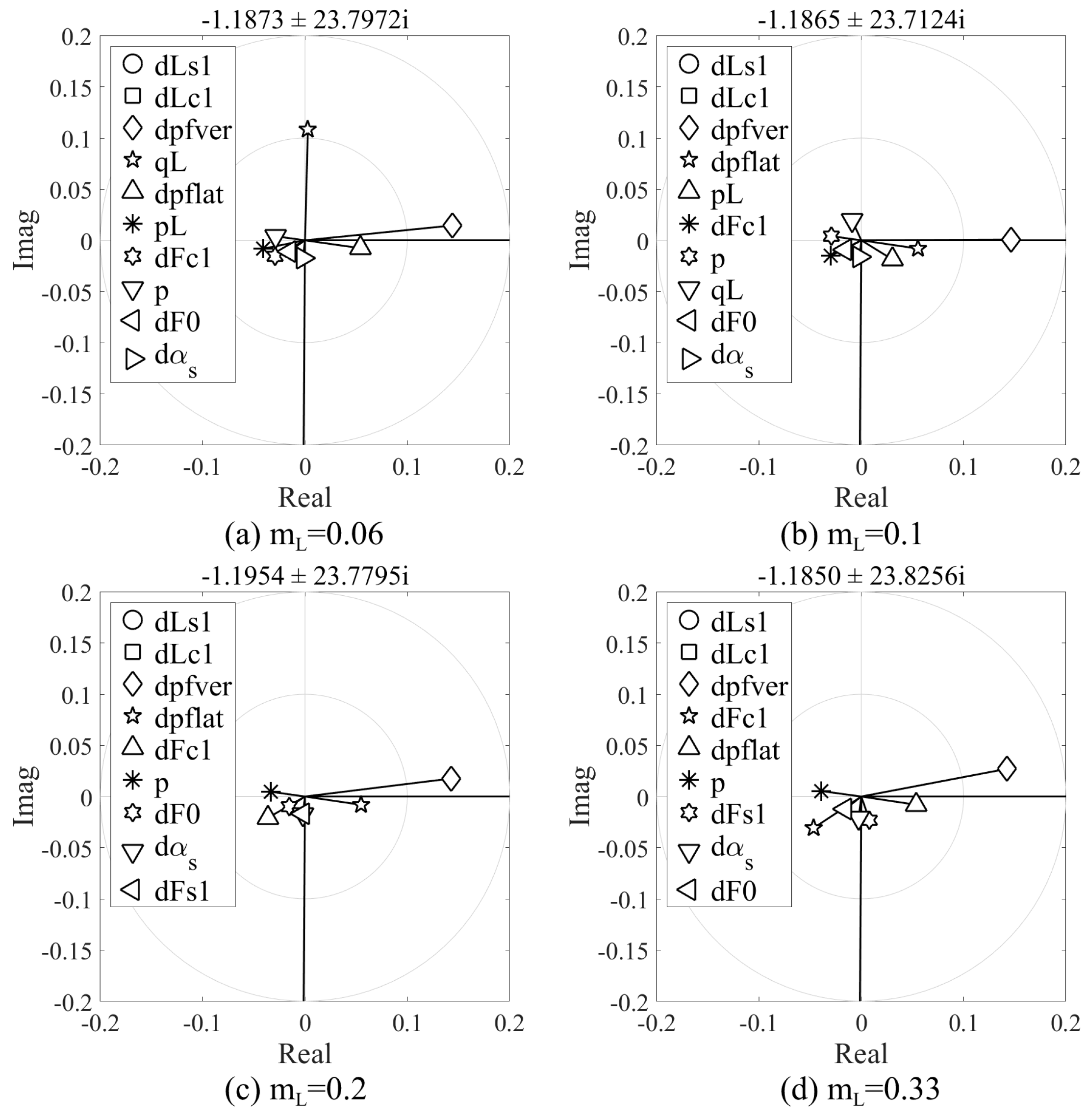
(1)
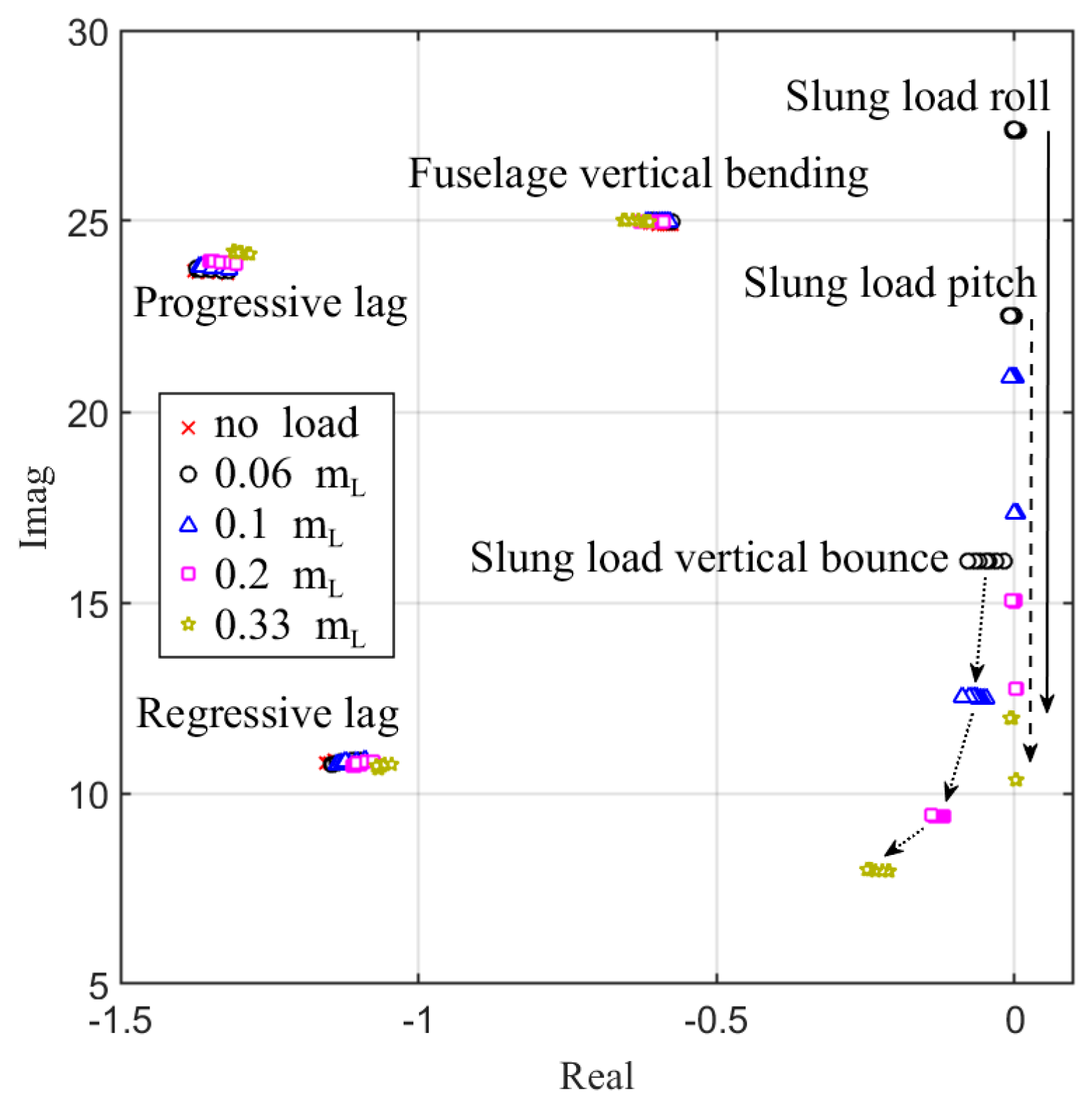
Influence mechanism of slung load mass on Category II RBSLCO
Figure 6 shows the effect of  m L  on critical eigenvalues related to Category II RBSLCO of the sample HSLS in different flight speeds. These critical eigenvalues are progressive and regressive lag modes, fuselage vertical bending mode and slung load rolling, and pitching and vertical bouncing modes.
It was found that the flight speed has few effects on the HSLS eigenvalues, while  m L  has slight effects on the stability margins of progressive and regressive lag modes as well as the fuselage vertical bending mode. As the  m L  increases, the stability margins of progressive and regressive lag modes decrease while the fuselage vertical bending mode stability margin increases, although the effects are relatively small. For example, the stability margin of the regressive lag mode decreases for about 10 %  at heavy load conditions.
It was also be found that the roll and pitch modes of the slung load are neutral oscillation modes.  m L  only affects their frequencies, which decrease as  m L  increases. However, there is a significant improvement of the vertical bouncing mode stability of the slung load with the increment of  m L .
In order to analyze the effect of  m L  on the coupling between the progressive lag and fuselage vertical bending modes, the coupling is analyzed without the slung load at first, as shown in Figure 7. The fuselage vertical bending frequency is set from 90 %  to 100 %  of its nominal value of 3.95 Hz. It can be found that their eigenvalues quickly approach each other followed with separation in the narrow frequency range. The frequency of the nearest approach of the two modes is located at 95.4 %  of nominal frequency with the reduction of the progressive lag mode stability margin at about 15 % . This indicates the coupling between the two modes can induce a decrease in stability when the frequencies of the two modes are close to each other.
Since the coupling is the strongest at 95.4 %  nominal frequency of the fuselage vertical bending mode, the effect of  m L  on the coupling is further studied. Figure 8 shows the effect of  m L  on the frequency and damping characteristics of the progressive lag and fuselage vertical bending modes. The horizontal axis is the ratio of rotational speed with respect to the operating rotational speed of the main rotor,  Ω ¯ , ranging from 0.94 to 1.06. The “no load” condition at  Ω ¯ = 1  corresponds to the condition with 95.4% frequency of the fuselage vertical bending mode in Figure 7. It can be seen in Figure 8 that the intersection point of frequency curves of the two modes shifts left as  m L  increases. The point is called as the resonant main rotor rotational speed as shown in Figure 8. At the resonant rotational speed, the damping ratio of the progressive lag mode is the least while that of the fuselage vertical bending mode is the largest. However, the peak values of the damping ratio of the two modes remain the same at the resonant rotational speed for different  m L .
Furthermore, Figure 9 shows the eigenvectors of the progressive lag mode for various  m L  at the resonant main rotor rotational speed. It was found that the rotor flapping motion (dFc1 in Figure 9) becomes more dominant as  m L  increases, while the slung load rolling and pitching motions (pL and qL in Figure 9) become less dominant. This indicates that the effect of the slung load motion on the progressive lag mode become weaker with the increment of  m L .
.
Based on the above analysis, Figure 10 shows the mechanism of the progressive lag and fuselage vertical bending mode coupled oscillation. The first-order harmonic lag motion is physically represented by the forward and backward movement of the combined center of the gravity of blades, which generates the longitudinal excitation force at the rotor hub. Then, the force transmits to the fuselage through the rotor shaft to generate a pitching moment, exciting the fuselage vertical bending oscillation, which causes additional forward and backward displacement of the rotor hub in return. Since the cable and slung load mode frequencies are far from the oscillation frequency, they are not involved in the progressive lag and fuselage vertical bending mode coupled oscillation.
(2)
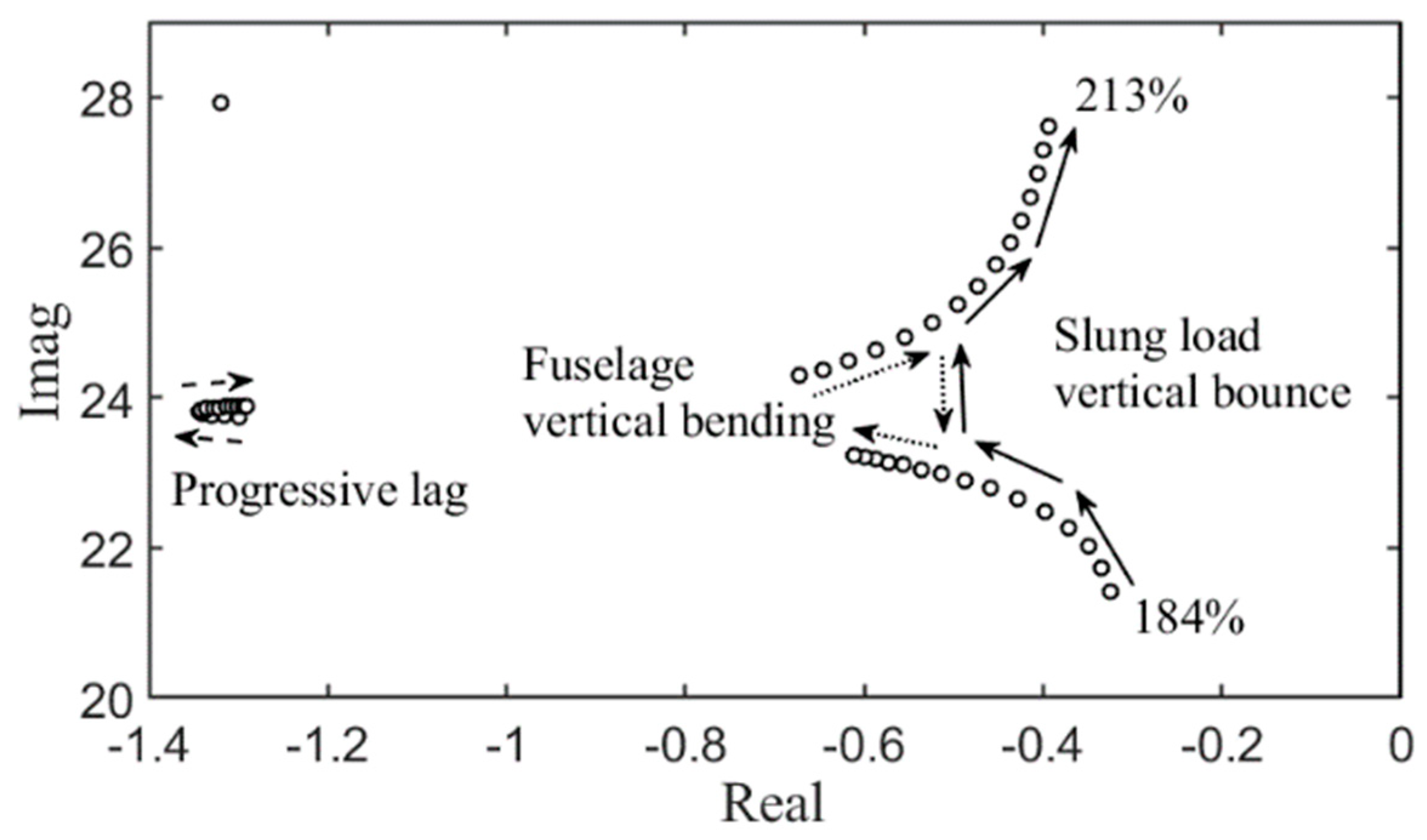
Influence mechanism of cable stiffness on Category II RBSLCO
Figure 11 shows the effect of cable stiffness on the coupling in progressive lag mode, fuselage vertical bending mode, and slung load vertical bouncing mode. Cable stiffness varies from 184% to 213% of nominal value  1.41 × 10 5   N / m  while  m L  equals to 0.06 and fuselage bending mode frequency equals to the baseline value of 95.4 % . It was found that the coupling between the slung load vertical bouncing mode and fuselage vertical bending mode becomes stronger as cable stiffness increases at first. Then, the coupling becomes weaker as cable stiffness continues to increase. However, the progressive lag mode has relatively smaller changes.
Figure 12 shows the coupled oscillation mechanism of the slung load vertical bouncing mode and fuselage vertical bending mode. The oscillation appears to be more like the “vertical bouncing” phenomenon when the slung load jumps upside down along with the fuselage vertical bending oscillation. When the slung load vertical bouncing mode frequency is lower than the fuselage vertical bending frequency, the fuselage bending mode behaves as the anti-phase oscillation shown in Figure 12a, while the slung load vertical bouncing mode behaves as the in-phase oscillation shown in Figure 12b. When the slung load vertical bouncing mode frequency is higher than the fuselage vertical bending frequency, the two oscillations are exchanged.

4. Conclusions

This paper gave a detailed description on the modeling and validation of the nonlinear rigid-elastic coupled HSLS model. Rotor dynamics, helicopter and slung load rigid-body motions, fuselage and cable elasticity, and nonlinear inertial, aerodynamic, and kinematic couplings were integrated into the model. The mechanism of Category II RBSLCO (2.5–8 Hz) was studied in detail. Through analysis, we concluded that:
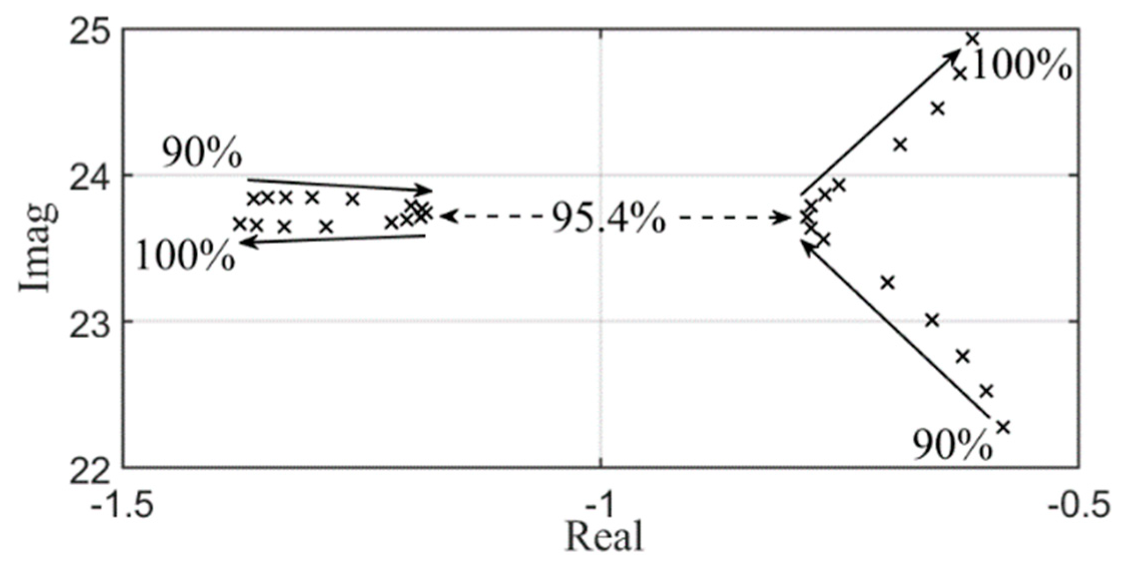
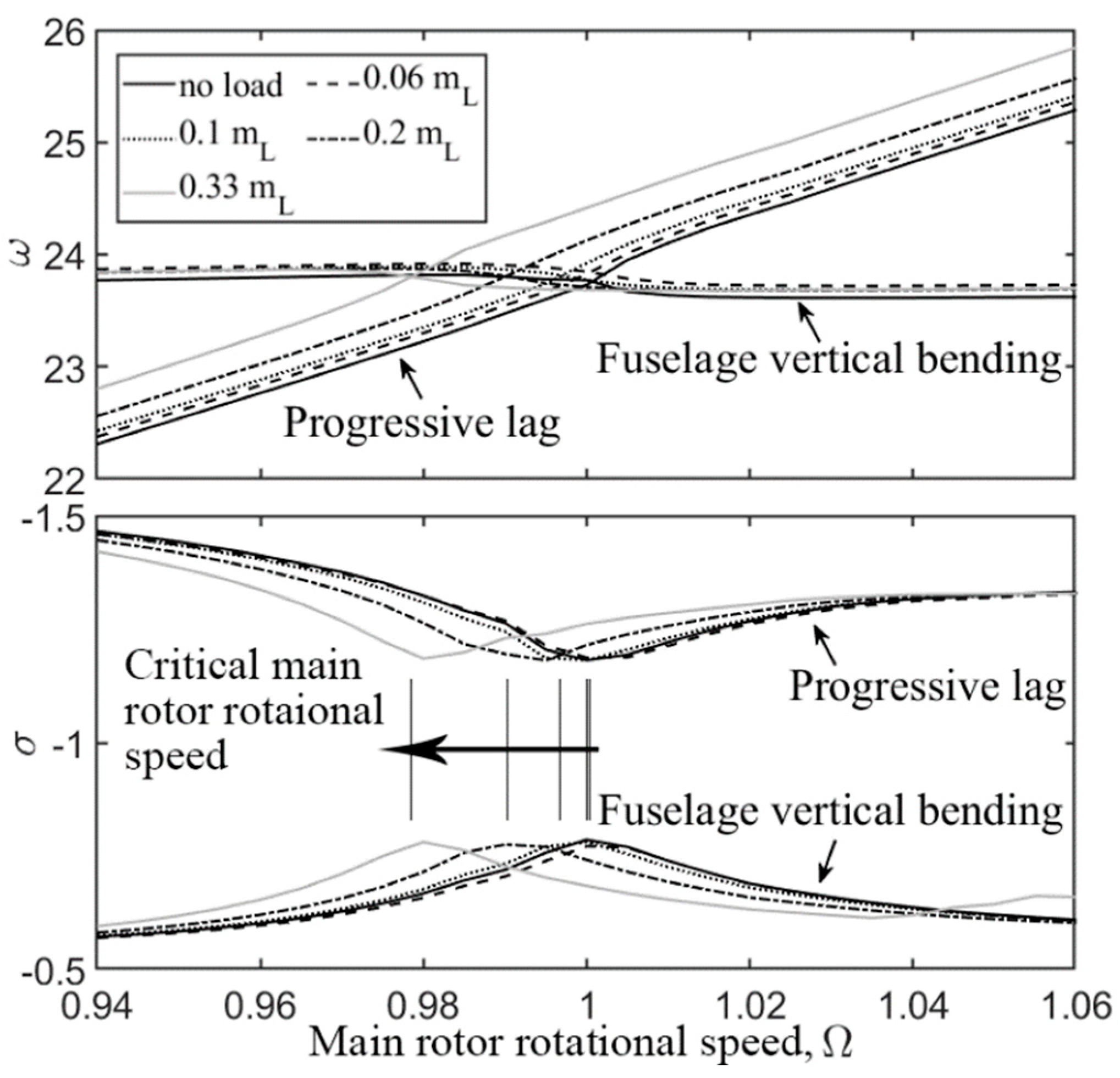
  • The coupling between the progressive lag mode and fuselage vertical bending mode became stronger for a larger slung load mass ratio. However, the airspeed had few influences on coupled characteristics. Thus, carrying the heaviest slung load was a vital state for Category II RBSLCO.
  • The coupling between the progressive lag mode and fuselage vertical bending mode caused a slight reduction of the stability margin of the progressive lag mode. Carrying a slung load also had a slight influence on the coupled oscillation frequency.
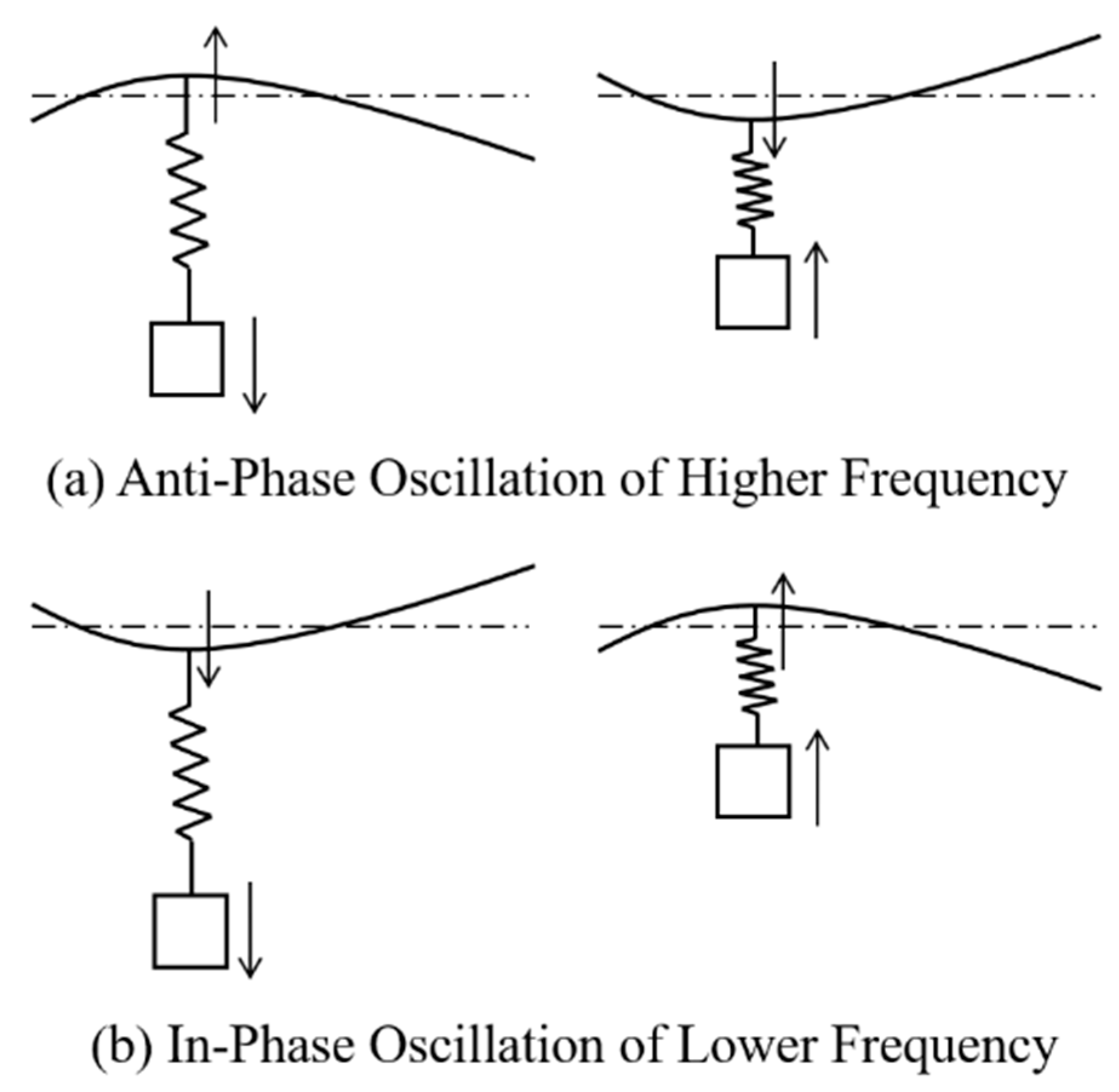
  • When cable stiffness was selected improperly, the slung load vertical bouncing mode frequency could approach the fuselage vertical bending mode frequency. This could cause the Category II RBSLCO to behave like the “vertical bouncing” phenomenon. The phenomenon included a high-frequency anti-phase oscillation and a relatively low-frequency in-phase oscillation.

Author Contributions

Conceptualization, L.W.; methodology, L.W.; software, L.W.; validation, Y.T.; formal analysis, Y.T., L.W., Z.Z. and R.C.; investigation, Y.T.; resources, R.C.; data curation, Z.Z.; writing—original draft preparation, Y.T. and L.W.; writing—review and editing, Y.T., L.W., Z.Z. and R.C.; visualization, Z.Z.; supervision, R.C.; project administration, L.W. and R.C.; funding acquisition, Z.Z. and R.C. All authors have read and agreed to the published version of the manuscript.

Funding

This research was funded by National Natural Science Foundation of China grant number 11672128, Project funded by the Priority Academic Program Development of Jiangsu Higher Education Institutions, Jiangsu Excellent Postdoctoral Program. And The APC was funded by National Natural Science Foundation of China grant number 11672128.

Data Availability Statement

The data presented in this study are available on request from the corresponding author. The data are not publicly available due to privacy or ethical restrictions.

Conflicts of Interest

The authors declare no conflict of interest.

References

  1. Manwaring, J.C.; Conway, G.A.; Garrett, L.C. Epidemiology and Prevention of Helicopter External Load Accidents. J. Saf. Res. 1998, 29, 107–121. [Google Scholar] [CrossRef]
  2. Walden, R.B. A Retrospective Survey of Pilot-Structural Coupling Instabilities in Naval Rotorcraft. In Proceedings of the the American Helicopter Society 63rd Annual Forum, Virginia Beach, VA, USA, 1–3 May 2007. [Google Scholar]
  3. Pavel, M.D.; Jump, M.; Dang-Vu, B.; Masarati, P.; Gennaretti, M.; Ionita, A.; Zaichik, L.; Smaili, H.; Quaranta, G.; Yilmaz, D.; et al. Adverse Rotorcraft Pilot Couplings—Past, Present and Future Challenges. Prog. Aeronaut. Sci. 2013, 62, 1–51. [Google Scholar] [CrossRef]
  4. Johnson, W. Recent Developments in the Dynamics of Advanced Rotor Systems, 2nd ed.; NASA Ames Research Center: Hampton, VA, USA, 1985. [Google Scholar]
  5. Kuczynsky, W.A.; Cooper, D.E.; Twomey, W.J.; Howlett, J.J. The Influence of Engine/Fuel Control Design on Helicopter Dynamics and Handling Qualities. J. Am. Helicopter Soc. 1980, 25, 26–34. [Google Scholar] [CrossRef]
  6. Lucassen, L.R.; Sterk, F.J. Dynamic Stability Analysis of A Hovering Helicopter with a Sling Load. J. Am. Helicopter Soc. 1965, 10, 6–12. [Google Scholar] [CrossRef]
  7. Dukes, T.A. Maneuvering Heavy Sling Loads Near Hover Part I: Damping the Pendulous Motion. J. Am. Helicopter Soc. 1973, 18, 2–11. [Google Scholar] [CrossRef]
  8. Ronen, T. Dynamics of a Helicopter with a Sling Load. Ph.D. Thesis, Stanford University, Stanford, CA, USA, 1986. [Google Scholar]
  9. Cicolani, L.S.; Kanning, G. Equations of Motion of Slung-Load Systems, Including Multilift Systems; Ames Research Center: Moffett Field, CA, USA, 1992. [Google Scholar]
  10. Cao, Y.; Nie, W.; Wang, Z.; Wan, S. Dynamic Modeling of Helicopter-Slung Load System under the Flexible Sling Hypothesis. Aerosp. Sci. Technol. 2020, 99, 105770. [Google Scholar] [CrossRef]
  11. Ivler, C. Design and Flight Test of a Cable Angle Feedback Control System for Improving Helicopter Slung Load Operations at Low Speed; Stanford University: Stanford, CA, USA, 2012. [Google Scholar]
  12. Enciu, J.; Singh, A.; Horn, J.F. Stabilization of External Loads in High-Speed Flight Using an Active Cargo Hook. J. Am. Helicopter Soc. 2020, 65, 1–12. [Google Scholar] [CrossRef]
  13. Ren, Y.; Li, K.; Ye, H. Modeling and Anti-Swing Control for a Helicopter Slung-Load System. Appl. Math. Comput. 2020, 372, 124990. [Google Scholar] [CrossRef]
  14. Komerath, N.; Hiremath, N.; Shukla, D. Testing-Based Approach to Determining the Divergence Speed of Slung Loads. Aerospace 2018, 5, 24. [Google Scholar] [CrossRef]
  15. Shaughnessy, J.D.; Deaux, T.N.; Yenni, K.R. Development and Validation Piloted Simulation Helicopter and External Sling Load; NASA: Hampton, VA, USA, 1979. [Google Scholar]
  16. Tyson, P.H. Simulation Validation and Flight Prediction of UH−60 Black Hawk Helicopter Slung Load Characteristics. Master’s Thesis, Nacal Postgraduate School, Monterey, CA, USA, 1999. [Google Scholar]
  17. Cicolani, L.S.; McCoy, A.H.; Sahai, R.; Tyson, P.H.; Tischler, M.B.; Rosen, A.; Tucker, G.E. Flight Test Identification and Simulation of a UH−60A Helicopter and Slung Load. J. Am. Helicopter Soc. 2001, 46, 140–160. [Google Scholar] [CrossRef]
  18. Cicolani, L.S.; Lusardi, J.; Greaves, L.D.; Robinson, D.; Rosen, A.; Raz, R. Flight Test Results for the Motions and Aerodynamics of a Cargo Container and a Cylindrical Slung Load; Army Aviation-Missile Research Development-Engineering Center: Moffett Field, CA, USA, 2010. [Google Scholar]
  19. Enciu, J.; Rosen, A. Simulation of Coupled Helicopter–Slung Load–Pilot Dynamics. J. Am. Helicopter Soc. 2017, 62, 1–13. [Google Scholar] [CrossRef]
  20. Bauchau, O.A.; Rodriguez, J.; Chen, S.-Y. Coupled Rotor-Fuselage Analysis with Finite Motions Using Component Mode Synthesis. J. Am. Helicopter Soc. 2004, 49, 201–211. [Google Scholar] [CrossRef]
  21. Cribbs, R.C.; Friedmann, P.P.; Chiu, T. Coupled Helicopter Rotor/Flexible Fuselage Aeroelastic Model for Control of Structural Response. AIAA J. 2000, 38, 1777–1788. [Google Scholar] [CrossRef]
  22. Meirovitch, L.; Tuzcu, I. The Lure of the MeanAxes. J. Appl. Mech. 2007, 74, 497–504. [Google Scholar] [CrossRef]
  23. Sahasrabudhe, V.; Faynberg, A.; Kubik, S.; Tonello, O.; Xin, H.; Engel, D.; Renfrow, J. CH-53K Control Laws: An Overview and Some Analytical Results. In Proceedings of the the American Helicopter Society 66th Annual Forum, Phoenix, AZ, USA, 11–13 May 2010. [Google Scholar]
  24. Sahasrabudhe, V.; Pozdin, M.; Cheng, R.; Tischler, M.; Stumm, A.; Lavin, M. Balancing CH-53K Handling Qualities and Stability Margin Requirements in the Presence of Heavy External Loads. In Proceedings of the the American Helicopter Society 63rd Annual Forum, Virginia Beach, VA, USA, 1–3 May 2007. [Google Scholar]
  25. Masarati, P.; Muscarello, V.; Quaranta, G. Linearized Aeroservoelastic Analysis of Rotary-Wing Aircraft. In Proceedings of the 36th European Rotorcraft Forum, Paris, France, 7–9 September 2010; Association Aéronautique & Astronautique de France: Paris, France, 2010. [Google Scholar]
  26. Wang, L.; Chen, R. Nonlinear Helicopter Rigid-Elastic Coupled Modeling with Its Applications on Aeroservoelasticity Analysis. AIAA J. 2022, 60, 102–112. [Google Scholar]
  27. Gassaway, B.; Strope, K.; Cicolani, L.; Lusardi, J.; He, C.; Robinson, M.D. Predictive Capabilities of a UH−60 FLIGHTLAB® Model with an External Sling Load. In Proceedings of the American Helicopter Society 62nd Annual Forum, Phoenix, AZ, USA, 9–11 May 2006. [Google Scholar]
  28. Dutton, W.J. Parametric Analysis and Preliminary Design of a Shaft-Driven Rotor System for a Heavy Lift Helicopter; Lockheed-California Company Division of Lockheed Aircraft Corporation: Burbank, CA, USA, 1967. [Google Scholar]
Figure 1. Illustration of a heavy lift helicopter and slung load system.
Aerospace 10 00872 g001
Figure 2. Couplings of a helicopter and slung load system.
Aerospace 10 00872 g002
Figure 3. Validation of UH−60A and CONEX container forward flight trimmed controls.
Aerospace 10 00872 g003
Figure 4. Definition and validation of UH−60A and CONEX container forward flight trimmed trail angle. (a) Trail angle definition. (b) Trimmed trail angle validation.
Aerospace 10 00872 g004
Figure 5. Frequency response validation of UH−60A and CONEX container  ϕ / δ l a t  at hovering.
Aerospace 10 00872 g005
Figure 6. Sample HSLS eigenvalues of various  m L  and flight speeds.
Aerospace 10 00872 g006
Figure 7. Progressive lag and fuselage vertical bending mode eigenvalues at various fuselage bending frequencies for isolated helicopter without slung load.
Aerospace 10 00872 g007
Figure 8. The effect of  m L  on frequency and damping characteristics of progressive lag mode and fuselage vertical bending mode.
Aerospace 10 00872 g008
Figure 9. Progressive lag eigenvectors of various  m L .
Aerospace 10 00872 g009
Figure 10. Category II RBSLCO mechanism of progressive lag and fuselage vertical bending.
Aerospace 10 00872 g010
Figure 11. Eigenvalues under various sling stiffness in 0.06  m L  at hovering.
Aerospace 10 00872 g011
Figure 12. Category II RBSLCO mechanism of slung load vertical bouncing and fuselage vertical bending.
Aerospace 10 00872 g012
Table 1. HSLS typical flight configurations.
TagMass, kgInertia kg·m2
  I x x   I y y   I z z
no load36,000214,880866,540735,540
0.06Helicopter33,936202,560816,858693,369
Slung Load2064187413461701
0.1Helicopter32,400193,392779,886661,986
Slung Load3600271519512466
0.2Helicopter28,800171,904693,232588,432
Slung Load7200431030973914
0.33Helicopter24,000143,253577,693490,360
Slung Load12,000605843535502
Disclaimer/Publisher’s Note: The statements, opinions and data contained in all publications are solely those of the individual author(s) and contributor(s) and not of MDPI and/or the editor(s). MDPI and/or the editor(s) disclaim responsibility for any injury to people or property resulting from any ideas, methods, instructions or products referred to in the content.

