
Study on Ground Experimental Method of Stagnation Point Large Heat Flux of Typical Sharp Wedge Leading Edge Structure


Abstract
:1. Introduction
2. CFD Numerical Simulation of the Sharp Wedge under Hypersonic Aerodynamic Heating
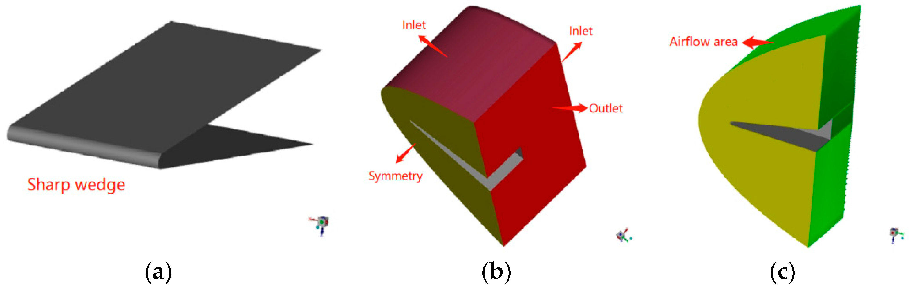
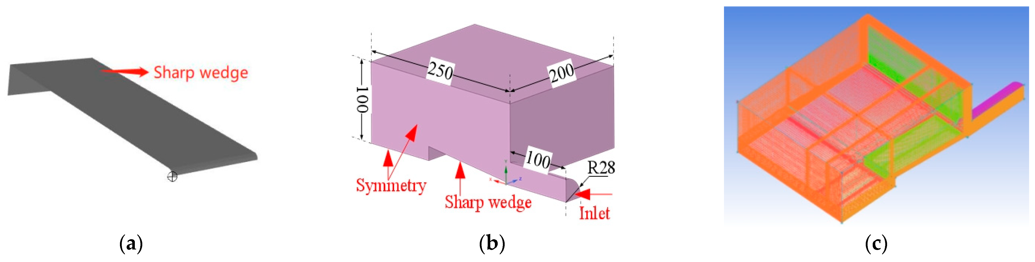
2.1. Computational Domain and Boundary Conditions
2.2. Governing Equations and Numerical Methods
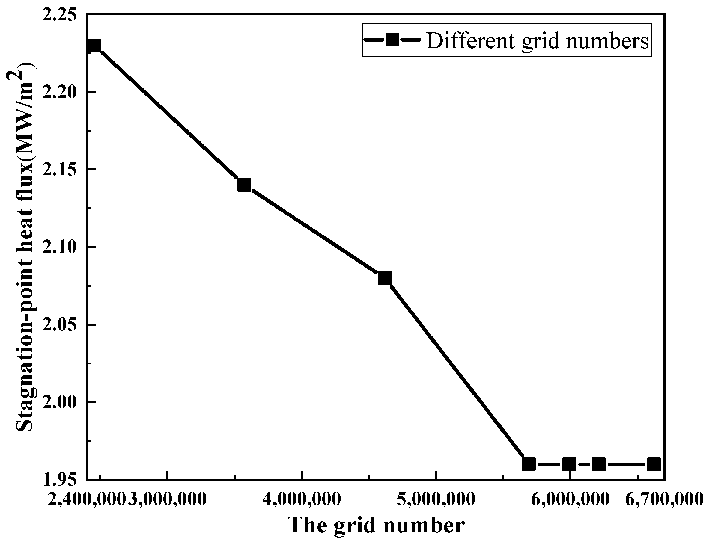
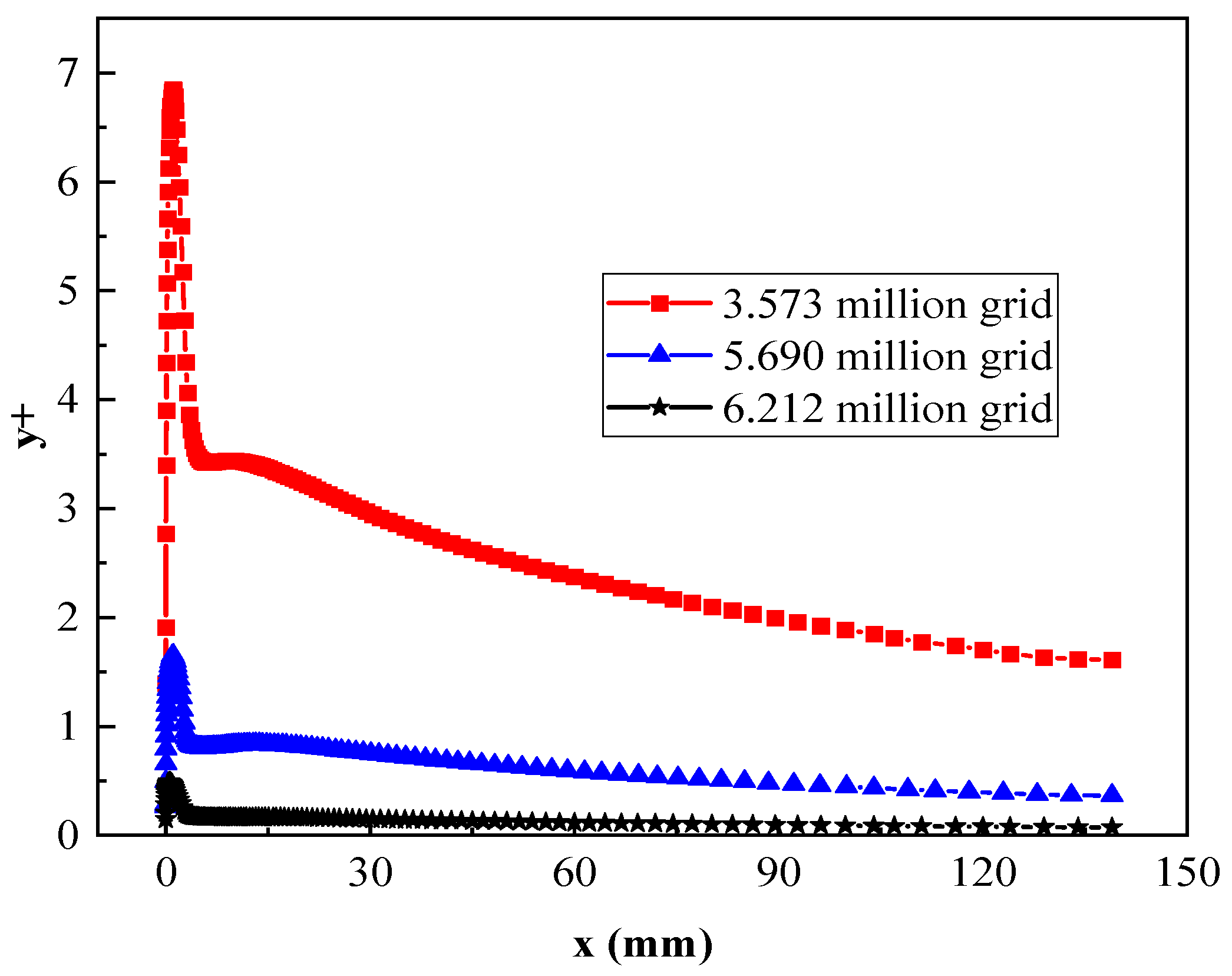
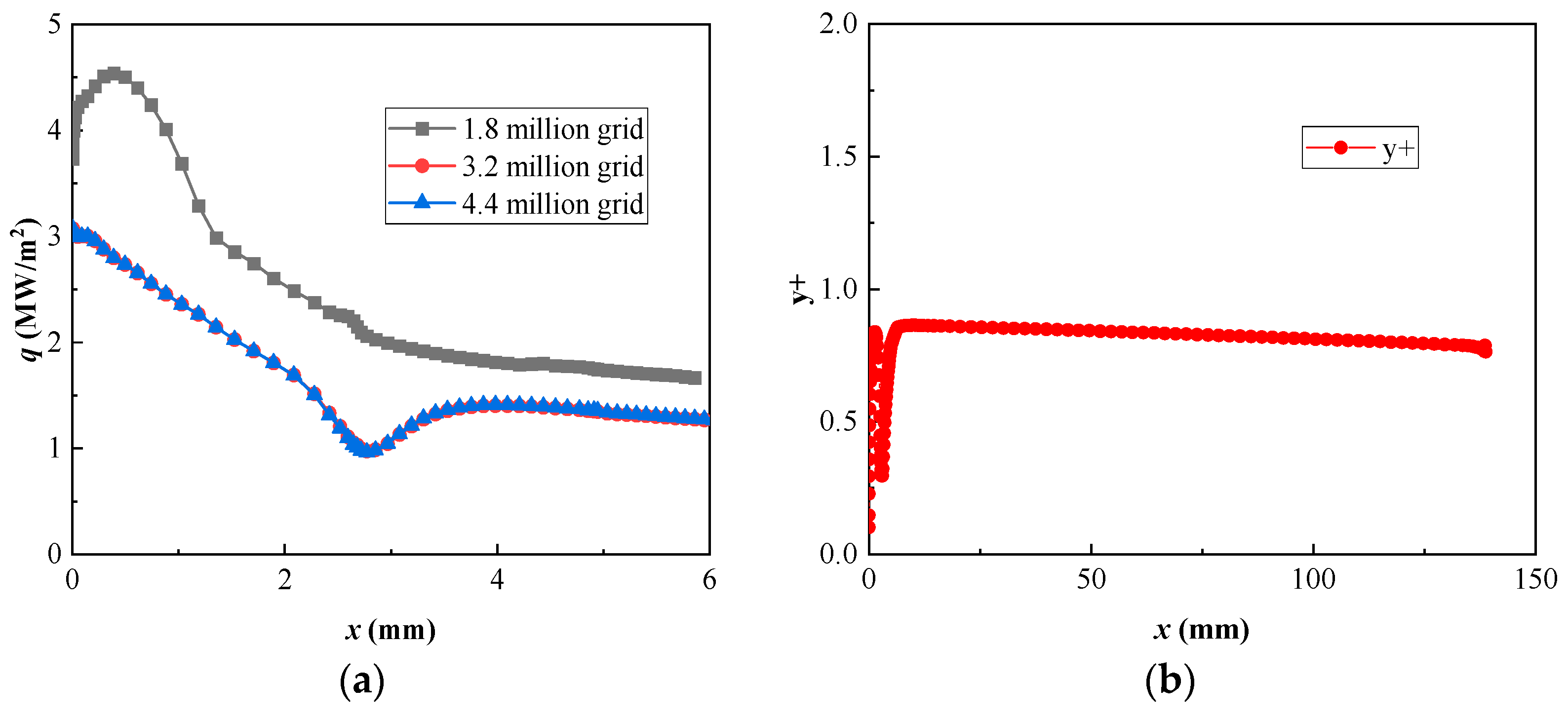
2.3. Grid Independence Verification
2.4. Stagnation Point Heat Flux Simulation Target
3. Experimental Device and Method
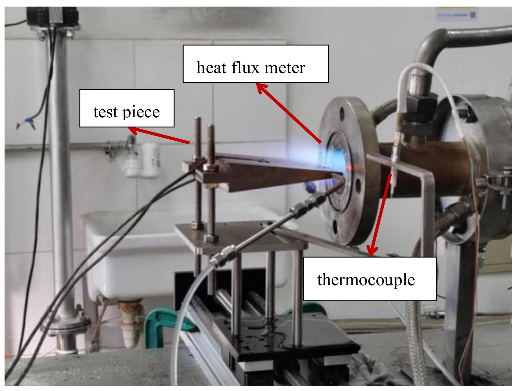
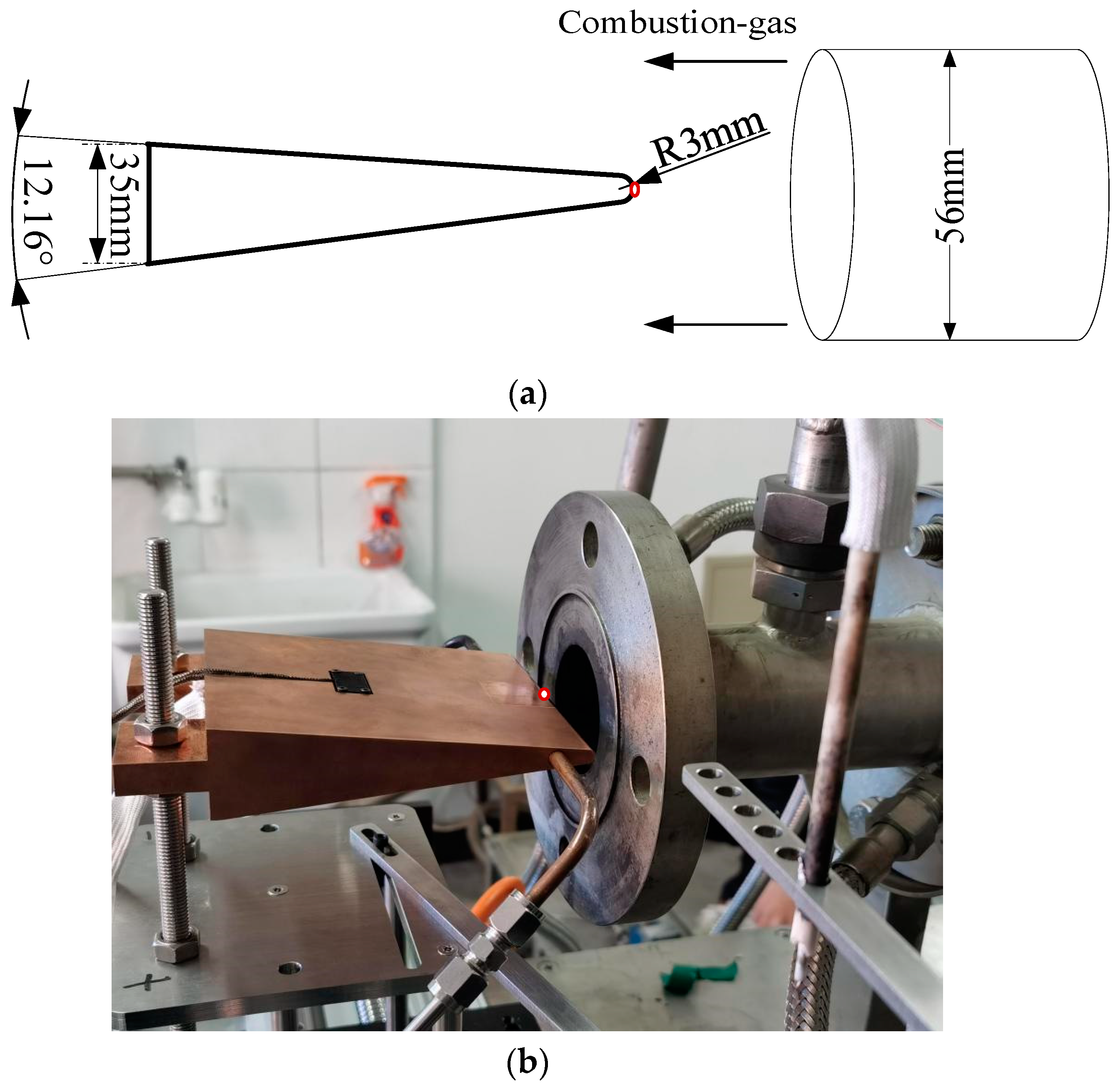
3.1. Experimental Device
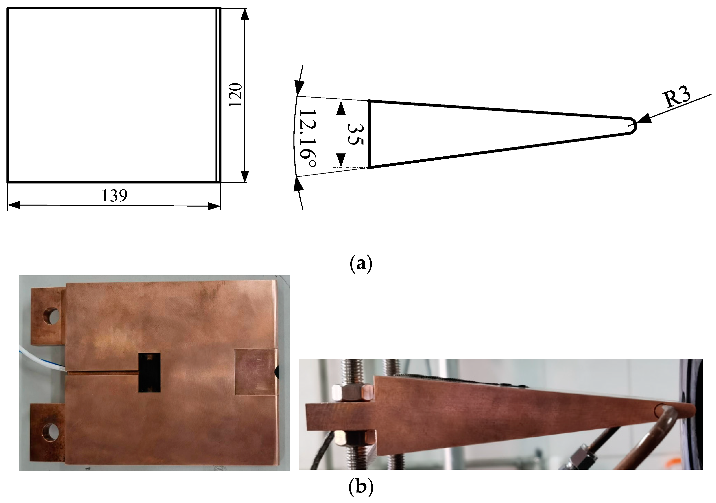
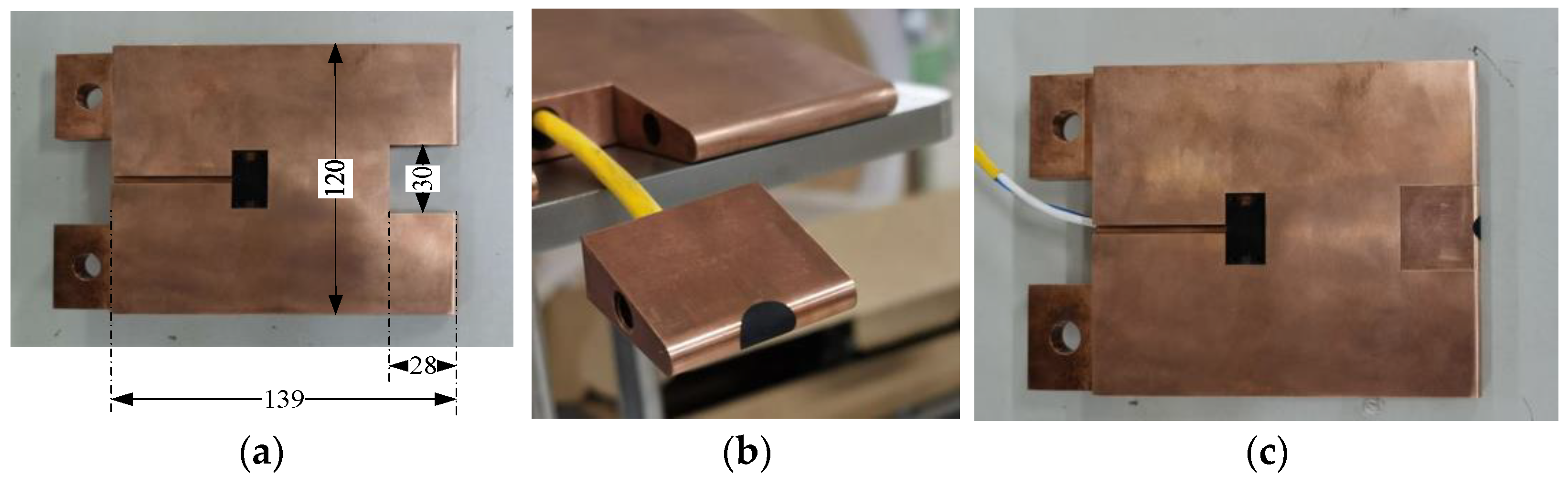
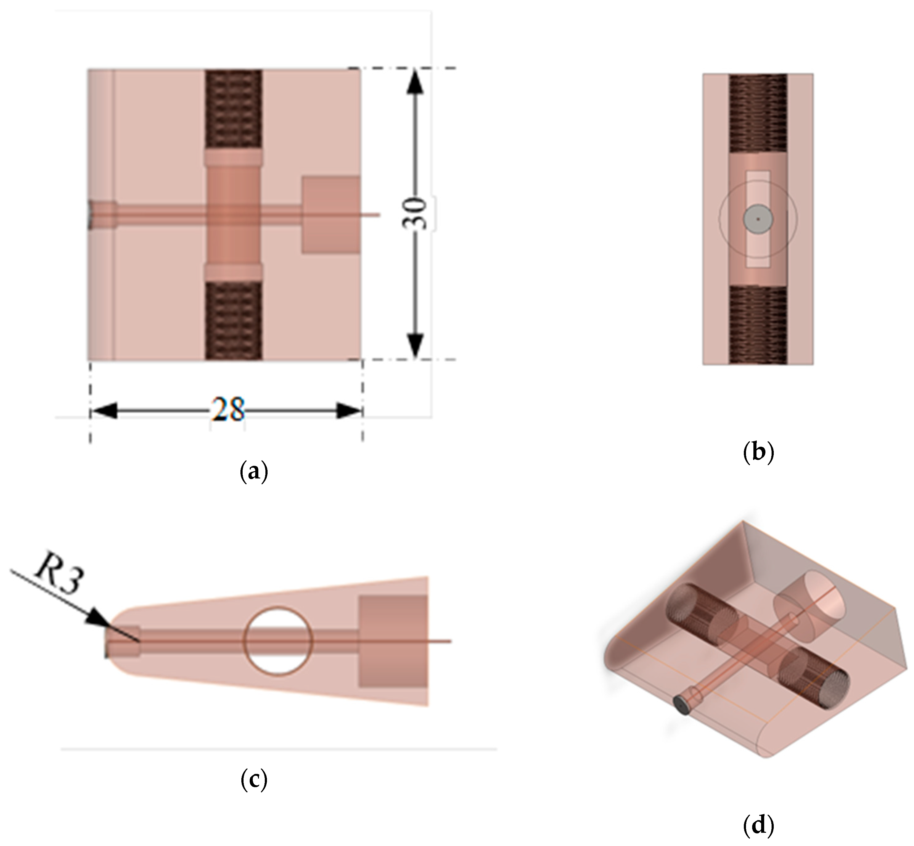
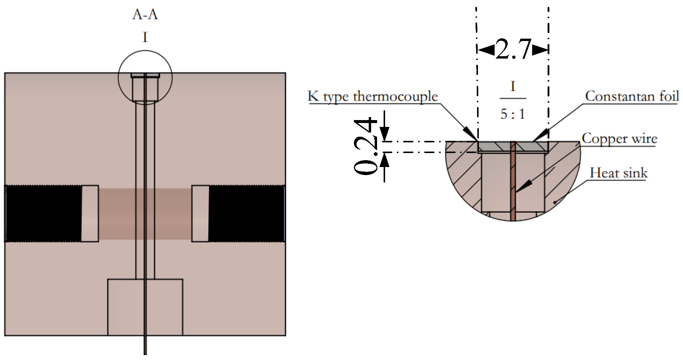
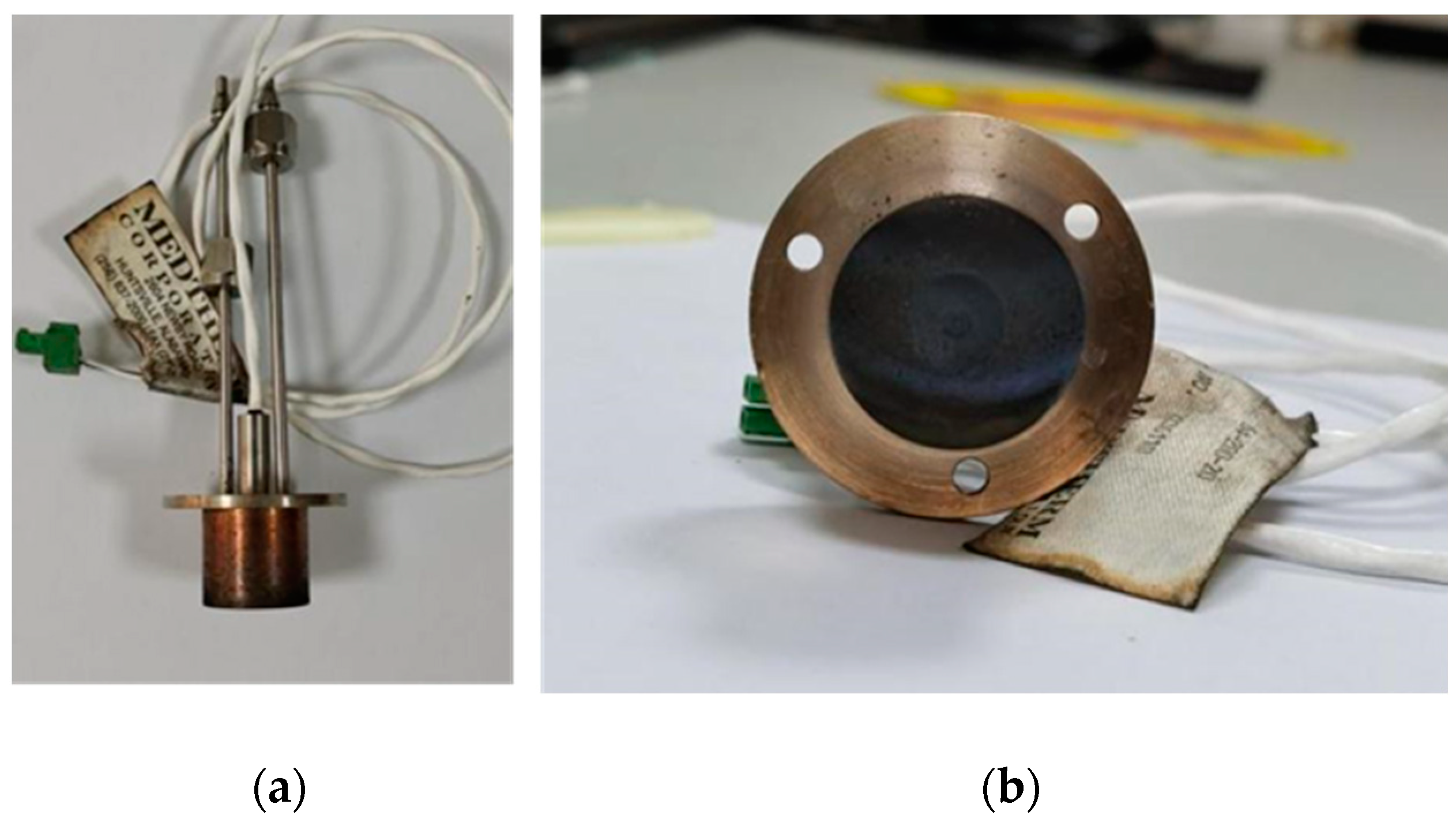
3.2. Experimental Specimen with Gardon Heat Flux Meter
3.3. Experimental Specimen Installation
3.4. Uncertainties of Experimental Parameters
3.5. Experimental Method
- ①
- Fixt the specimen with the water-cooled Gardon heat flux meter and temperature thermocouple on the slide rail support, respectively, with the height of adjustment consistent with the center position of the nozzle, as close as possible to the section of the nozzle;
- ②
- Start the chiller, with the water supply temperature of the cooling water at 4 °C. Start the measurement and control system, and set the sampling frequency of heat flow to 0.2 s/time;
- ③
- Debug the electric slide rail, first move the heat flux meter to the center of the airflow as the initial position, and then enter the command +200 mm to move the thermocouple to the center of the airflow;
- ④
- Open the high pressure air supply system, and adjust the air quality flow rate at 150 g/s;
- ⑤
- Start the combustion gas generator, keep the ignition state, and burn steadily for 60 s;
- ⑥
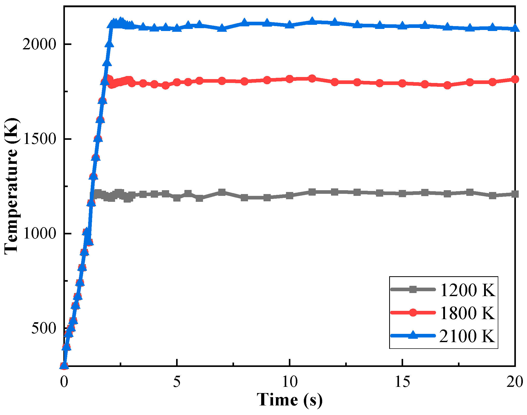
- Set the gas flow temperature control target, turn on the measurement and control system to automatically adjust the oil supply flow, and burn steadily for more than 30 s after reaching the control target;
- ⑦
- Input the sliding rail movement instruction so that the heat flux meter quickly reaches the experimental median. After 30 s, input the sliding rail movement instruction again, so that the heat flux meter moves back to the initial position and the thermocouple reaches the airflow center.
- ⑧
- Repeat steps 5 and 6 to complete a variety of gas flow temperature condition tests.
- ⑨
- Adjust the fuel flow to the ignition state, and when combustion is stable for over 60 s, close the oil supply valve so that the burner is extinguished, and stop data collection.
4. Construction of the Kriging Surrogate Model
4.1. Method Overview
- (1)
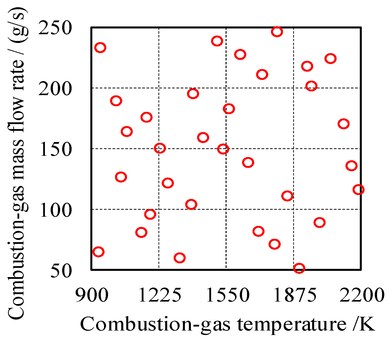
- Use the Latin hypercube sampling method to obtain sample points in the design space.
- (2)
- Under SHCH conditions, use the CFD numerical simulation to obtain the stagnation point heat flux density of the sharp wedge.
- (3)
- Use the Kriging surrogate model to construct an approximate fitting relationship between the design sample points and stagnation point heat flux. Analyze the accuracy of the constructed surrogate model, and if the accuracy is not satisfactory, reconstruct the model by increasing the number of sample points until the accuracy meets the requirements.
- (4)
- Take the specified hypersonic aerodynamic heat flux as the target value and solve for the corresponding experimental parameters.
4.2. Obtaining Sample Points in the Design Space
4.3. Generation of Stagnation Point Heat Flux by CFD Numerical Simulation
4.4. Kriging Surrogate Model of Combustion Gas Heating Flux
4.5. Uncertainty Analysis
5. Experimental Results and Discussion
5.1. Combustion Gas Temperature Determination Based on Kriging Surrogate Model
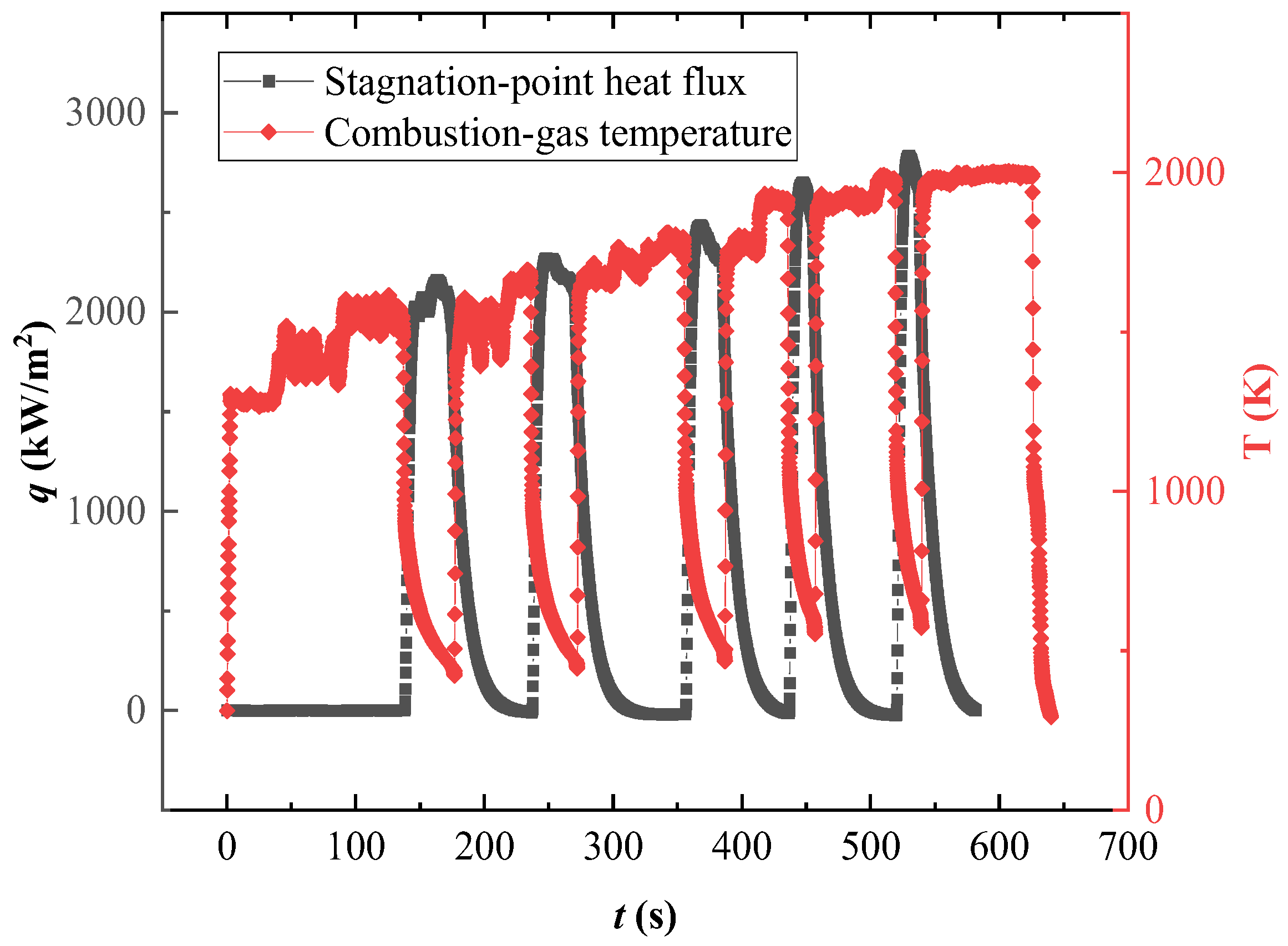
5.2. Experimental Results
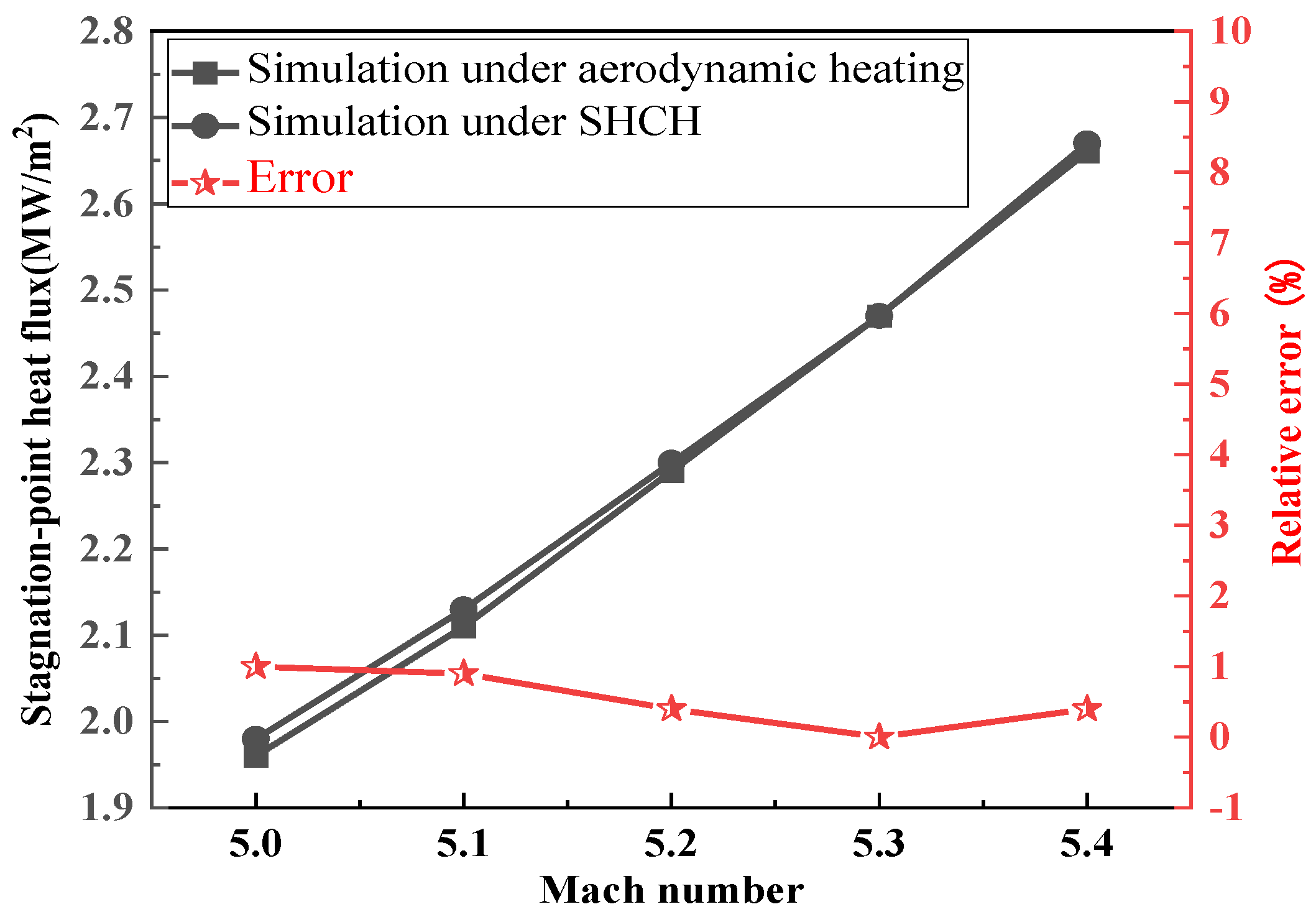
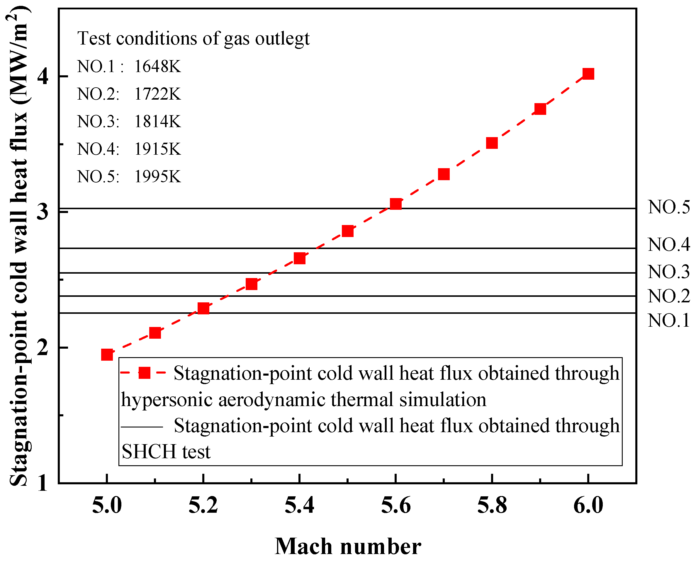
5.3. Verification of the Stagnation Point Heat Flux Simulation Ability of SHCH
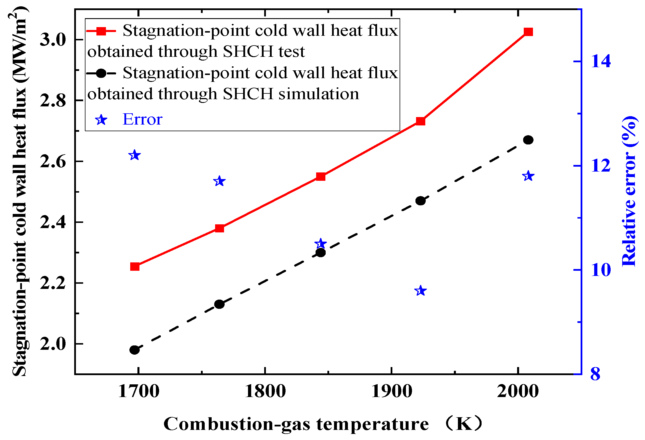
5.4. Verification of the Accuracy of Numerical Simulation of High-Temperature Gas Flow
- (1)
- The numerical simulations did not account for the radiation from the combustion gas flow. In the CFD numerical simulation of ground gas flow, the outer surface of the sharp wedge was set to 300 K, and the obtained heat flux was the 300 K cold wall heat flux. At this time, the heat radiating outward was relatively small, and the radiation model was not opened because of its complexity. In the actual test process, the wall temperature gradually rose and finally converted into the 300 K cold wall heat flux, so radiation heat transfer was considered in the test process. However, in reality, due to the presence of moisture molecules in the combustion products of fuel at higher temperatures, there is a certain radiative capability under high-temperature conditions. Therefore, in the comparison between the simulation and experimental results, the experimental results were higher.
- (2)
- During the test, the leading edge of the sharp wedge was very close to the nozzle, and the surroundings of the test piece were enveloped by the gas flow. In this region, some combustion reactions might have occurred within the gas flow, leading to an enhancement in the actual heat capability. Such complex scenarios were not considered in the numerical simulations. Another factor is that the heat dissipation environment near the stagnation point differed in the simulations, as the outlet consisted of a predetermined temperature airflow devoid of any combustion process. However, in practical experiments, the stagnation point was enveloped by gas flames, potentially still harboring combustion reactions. The heat dissipation conditions might have been poor, leading to larger measured heat flux values.
- (3)
- As mentioned above, the actual measurement results of the Gardon heat flux meter corresponded to the average heat flux in the arc area, which was very small near the stagnation point and should be lower than the stagnation point heat flow value, in theory. The measured results were higher than the numerical simulation results of the stagnation point heat flux, which showed that the deviation from the numerical simulation results should be slightly increased on the current basis.
6. Conclusions
Author Contributions
Funding
Data Availability Statement
Conflicts of Interest
References
- Lou, F.; Dong, S.; Ma, Y.; Qi, B.; Zhu, K. Numerical study of the influence of coupling interface emissivity on aerogel metal thermal protection performance. Gels 2021, 7, 250. [Google Scholar] [CrossRef]
- Huang, W.; Yan, L.; Liu, J.; Jin, L.; Tan, J. Drag and heat reduction mechanism in the combinational opposing jet and acoustic cavity concept for hypersonic vehicles. Aerosp. Sci. Technol. 2015, 42, 407–414. [Google Scholar] [CrossRef]
- Mashaei, P.; Shahryari, M.; Madani, S. Analytical study of multiple evaporator heat pipe with nanofluid; A smart material for satellite equipment cooling application. Aerosp. Sci. Technol. 2016, 59, 112–121. [Google Scholar] [CrossRef]
- Qin, Q.; Xu, J. Numerical evaluation of aerodrome and cooling jet for aero heating reduction. Aerosp. Sci. Technol. 2019, 86, 520–533. [Google Scholar] [CrossRef]
- Rivier, M.; Lachaud, J.; Congedo, P. Ablative thermal protection system under uncertainties including pyrolysis gas composition. Aerosp. Sci. Technol. 2019, 84, 1059–1069. [Google Scholar] [CrossRef]
- Zhu, L.; Li, Y.; Chen, X.; Li, H.; Li, W.; Li, C. Hypersonic flow characteristics and relevant structure thermal response induced by the novel combined spike-aerodome and lateral jet strategy. Aerosp. Sci. Technol. 2019, 95, 105459. [Google Scholar] [CrossRef]
- Kuznetsov, A.; Lunev, V. Heating of a Sharp Slender Wedge in Supersonic Flow. Fluid Dyn. 2021, 56, 116–120. [Google Scholar] [CrossRef]
- Mao, X.; Cao, W. Prediction of hypersonic boundary layer transition on sharp wedge flow considering variable specific heat. Appl. Math. Mech. 2014, 35, 143–154. [Google Scholar] [CrossRef]
- Kasen, S.; Wadley, H. Heat Pipe Thermal Management at Hypersonic Vehicle Leading Edges: A Low Temperature Model Study. J. Therm. Sci. Eng. Appl. 2019, 11, 061001. [Google Scholar] [CrossRef]
- Li, S.; Huang, W.; Lei, J.; Wang, Z. Drag and heat reduction mechanism of the porous opposing jet for variable blunt hypersonic vehicles. Int. J. Heat Mass Transf. 2018, 126, 1087–1098. [Google Scholar] [CrossRef]
- Zhang, R.; Huang, W.; Li, L.; Yan, L.; Moradi, R. Drag and heat flux reduction induced by the pulsed counterflowing jet with different periods on a blunt body in supersonic flows. Int. J. Heat Mass Transf. 2018, 127, 503–512. [Google Scholar] [CrossRef]
- Wang, Z.; Sun, X.; Huang, W.; Li, S.; Yan, L. Experimental investigation on drag and heat flux reduction in supersonic/hypersonic flows: A survey. Acta Astronaut. 2016, 129, 95–110. [Google Scholar] [CrossRef]
- Ou, M.; Yan, L.; Huang, W.; Li, S.; Li, L. Detailed parametric investigations on drag and heat flux reduction induced by a combinational spike and opposing jet concept in hypersonic flows. Int. J. Heat Mass Transf. 2018, 126, 10–31. [Google Scholar] [CrossRef]
- Reddy, D.; Saikia, B.; Sinha, K. Effect of High-Enthalpy Air Chemistry on Stagnation Point Heat Flux. J. Thermophys. Heat Transf. 2014, 28, 356–359. [Google Scholar] [CrossRef]
- Rocher, M.; Hermann, T.; McGilvray, M. Correlation for Species Concentration on a Hypersonic Stagnation Point with Mass Injection. AIAA J. 2022, 60, 2798–2809. [Google Scholar] [CrossRef]
- Ju, S. Study on Testing Environment Simulation Method for Thermal Flux Density of Aerothermal. J. Phys. Conf. Ser. 2019, 1267, 012065. [Google Scholar]
- Simonenko, E.P.; Simonenko, N.P.; Gordeev, A.N.; Papynov, E.K.; Shichalin, O.O.; Kolesnikov, A.F.; Avramenko, V.A.; Sevastyanov, V.G.; Kuznetsov, N.T. Study of the Thermal Behavior of Wedge-Shaped Samples of HfB2-45 vol % SiC Ultra-High-Temperature Composite in a High-Enthalpy Air Flow. Russ. J. Inorg. Chem. 2018, 63, 421–432. [Google Scholar] [CrossRef]
- Monteverde, F.; Savino, R. ZrB2–SiC Sharp Leading Edges in High Enthalpy Supersonic Flows. J. Am. Ceram. Soc. 2012, 95, 2282–2289. [Google Scholar] [CrossRef]
- Yang, J.; Liu, M. A wall grid scale criterion for hypersonic aerodynamic heating calculation. Acta Astronaut. 2017, 136, 137–143. [Google Scholar] [CrossRef]
- Liu, J.; Hou, Z.; Ding, G.; Chen, X.; Chen, X. Numerical and experimental study on waverider with blunt leading edge. Comput. Fluids 2013, 84, 203–217. [Google Scholar] [CrossRef]
- Lees, L. Laminar Heat Transfer Over Blunt-Nosed ies at Hypersonic Flight Speeds. J. Jet Propuls. 1956, 26, 259–269. [Google Scholar] [CrossRef]
- Fay, J.; Riddell, F. Theory of Stagnation Point Heat Transfer in Dissociated Air. J. Aerosp. Sci. 1958, 25, 73–85. [Google Scholar] [CrossRef]
- Regan, F.; Anandakrishnan, S. Dynamics of Atmospheric Re-Entry; American Institute of Aeronautics and Astronautics Press: Reston, VA, USA, 1993. [Google Scholar]
- Singh, N.; Schwartzentruber, T. Heat flux correlation for high-speed flow in the transitional regime. J. Fluid Mech. 2016, 792, 981–996. [Google Scholar] [CrossRef]
- Gross, E.; Jackson, E. Kinetic models and the linearized Boltzmann equation. Phys. Fluids 1959, 2, 432–441. [Google Scholar] [CrossRef]
- Mott-Smith, H. The Solution of the Boltzmann Equation for a Shock Wave. Phys. Rev. 1951, 82, 885–892. [Google Scholar] [CrossRef]
- Bhatnagar, P.; Gross, E.; Krook, M. A Model for Collision Processes in Gases. I. Small Amplitude Processes in Charged and Neutral One-Component Systems. Phys. Rev. 1954, 94, 511–525. [Google Scholar] [CrossRef]
- Xiao, F.; Li, Z.; Zhang, Z.; Zhu, Y.; Yang, J. Hypersonic Shock Wave Interactions on a V-Shaped Blunt Leading Edge. AIAA J. 2018, 56, 356–367. [Google Scholar] [CrossRef]
- Li, B.; Bao, L.; Tong, B. Physical criterion study on forward stagnation point heat flux CFD computations at hypersonic speeds. Appl. Math. Mech. 2010, 31, 839–850. [Google Scholar] [CrossRef]
- Dong, S.; Li, Z. Research on the combined heating method using dual subsonic gas flow of high and middle temperature for thermal test of tip wedge structure. In Proceedings of the 18th AIAA/3AF International Space Planes and Hypersonic Systems and Technologies Conference, Tours, France, 24–28 September 2012. [Google Scholar]
- Kolesnikov, A. Conditions of simulation of stagnation point heat transfer from a high-enthalpy flow. Fluid Dyn. 1993, 28, 131–137. [Google Scholar] [CrossRef]
- Kolesnikov, A. The concept of local simulation for stagnation point heat transfer in hypersonic flows—Applications and validation. In Proceedings of the 21st Aerodynamic Measurement Technology and Ground Testing Conference, Denver, CO, USA, 19–22 June 2000. [Google Scholar]
- Yang, S.; Tao, W. Heat Transfer; Higher Education Press: Beijing, China, 2014. [Google Scholar]
- Wang, W.; Qian, W.; Bai, Y.; Wang, K. Numerical studies on the thermal-fluid-structure coupling analysis method of hypersonic flight vehicle. Therm. Sci. Eng. Prog. 2023, 40, 101792. [Google Scholar] [CrossRef]
- Lou, F.; Dong, S.; Zhao, B.; Qi, B. Structure design and performance test of a high temperature combustor based on combustion-gas wind tunnel device. Heat Transf. Res. 2022, 53, 21–36. [Google Scholar] [CrossRef]
- A, R.; Qi, B.; Chen, X.; Wang, R.; Song, S.; Zhou, Y. Parameter optimization of dual gas flow combined thermal test based on surrogate model. J. Aerosp. Power 2023, 38, 2097–2106. [Google Scholar]
- Xiong, K.; Li, Y.; Dong, S. Temperature distribution of a test specimen with high-speed heat airflow passing through. Therm. Sci. 2018, 22, 2527–2538. [Google Scholar] [CrossRef]
- Simpson, T.W.; Mauery, T.M.; Korte, J.J.; Mistree, F. Kriging Models for global approximation in simulation-based multidisciplinary design optimization. AIAA J. 2001, 39, 2233–2241. [Google Scholar] [CrossRef]


| Grid Number (Million) | Grid Height of the First Layer (mm) |
|---|---|
| 2.456 | 0.05 |
| 3.573 | 0.02 |
| 4.619 | 0.01 |
| 5.690 | 0.007 |
| 5.990 | 0.005 |
| 6.212 | 0.002 |
| 6.623 | 0.001 |
| Mach Number | Stagnation Point Heat Flux (MW/m2) |
|---|---|
| 6.5 | 5.54 |
| 6 | 4.02 |
| 5.5 | 2.86 |
| 5 | 1.98 |
| 4.5 | 1.35 |
| 4 | 0.88 |
| Sensor | Number | Accuracy | Full Scale | Model |
|---|---|---|---|---|
| Temperature | 1 | ±1 K | 2100 K | B type |
| Flow meter | 2 | ±0.2% of full scale | 180 g/s | Shouke |
| Gardon heat flux meter | 1 | ±3% of full scale | 3 MW/m2 | GD-4000 |
| Recirculating cooler | 1 | ±0.2% of full scale | 313 K | FLW2503 |
| Data acquisition instrument | 1 | ±0.2% of full scale | - | HP34972A |
| Flattening oven | 1 | 3% | - | HFC-3000 |
| Component | CO2 | H2O | O2 | N2 |
| Mass proportion (%) | 14.8 | 72.9 | 6.7 | 5.6 |
| Test Condition | Combustion Gas Temperature (K) | Combustion Gas Mass Flow (g/s) | Predicted Heat Flux of Surrogate Model (MW/m2) | Calculated Heat Flux Value of CFD (MW/m2) |
|---|---|---|---|---|
| 1 | 930 | 200 | 0.7589 | 0.756 |
| 2 | 2064 | 70.6 | 1.8866 | 1.88 |
| 3 | 1328 | 110 | 1.0874 | 1.09 |
| 4 | 1821 | 210 | 2.6825 | 2.68 |
| No. | Target Stagnation Point Heat Flux | Optimal SHCH Test Conditions Based on Kriging Surrogate Model | |||
|---|---|---|---|---|---|
| Mach Number | Stagnation Point Cold Wall Heat Flux (MW/m2) | Combustion Gas Mass Flow (g/s) | Combustion Gas Temperature (K) | Mach Number | |
| 1 | 5.0 | 1.96 | 150 | 1697 | 0.36 |
| 2 | 5.1 | 2.11 | 150 | 1764 | 0.37 |
| 3 | 5.2 | 2.29 | 150 | 1844 | 0.38 |
| 4 | 5.3 | 2.47 | 150 | 1923 | 0.39 |
| 5 | 5.4 | 2.66 | 150 | 2008 | 0.40 |
| No. | Test Conditions | Gardon Heat Flux Meter | Cold Wall Heat Flux of 300 K (MW/m2) | ||
|---|---|---|---|---|---|
| Ma | Gas Temperature (K) | Temperature (K) | Stagnation Point Heat Flux (MW/m2) | ||
| 1 | 0.35 | 1648 | 366 | 2.14 | 2.255 |
| 2 | 0.36 | 1722 | 370 | 2.26 | 2.38 |
| 3 | 0.37 | 1814 | 377 | 2.42 | 2.55 |
| 4 | 0.38 | 1915 | 384 | 2.59 | 2.732 |
| 5 | 0.39 | 1995 | 466 | 2.73 | 3.026 |
| No. | Hypersonic Conditions | Gas Temp | Experimental Results | Deviation | |||||
|---|---|---|---|---|---|---|---|---|---|
| Ma | STP CW HFlux | Gas Temp | STP Temp | STP HFlux | STP CW HFlux | Gas Temp | CW HFlux | ||
| MW/m2 | K | K | K | MW/m2 | MW/m2 | K | % | ||
| 1 | 5.0 | 1.96 | 1697 | 1648 | 366 | 2.14 | 2.255 | −49 | +13.1 |
| 2 | 5.1 | 2.11 | 1764 | 1722 | 370 | 2.26 | 2.38 | −42 | +11.3 |
| 3 | 5.2 | 2.29 | 1844 | 1814 | 377 | 2.42 | 2.55 | −30 | +10.2 |
| 4 | 5.3 | 2.47 | 1923 | 1915 | 384 | 2.59 | 2.732 | −8 | +9.6 |
| 5 | 5.4 | 2.66 | 2008 | 1995 | 466 | 2.73 | 3.026 | −13 | +12.1 |
Disclaimer/Publisher’s Note: The statements, opinions and data contained in all publications are solely those of the individual author(s) and contributor(s) and not of MDPI and/or the editor(s). MDPI and/or the editor(s) disclaim responsibility for any injury to people or property resulting from any ideas, methods, instructions or products referred to in the content. |
© 2023 by the authors. Licensee MDPI, Basel, Switzerland. This article is an open access article distributed under the terms and conditions of the Creative Commons Attribution (CC BY) license (https://creativecommons.org/licenses/by/4.0/).
Share and Cite
Wang, R.; Lou, F.; Qi, B.; A, R.; Zhou, Y.; Dong, S. Study on Ground Experimental Method of Stagnation Point Large Heat Flux of Typical Sharp Wedge Leading Edge Structure. Aerospace 2023, 10, 871. https://doi.org/10.3390/aerospace10100871
Wang R, Lou F, Qi B, A R, Zhou Y, Dong S. Study on Ground Experimental Method of Stagnation Point Large Heat Flux of Typical Sharp Wedge Leading Edge Structure. Aerospace. 2023; 10(10):871. https://doi.org/10.3390/aerospace10100871
Chicago/Turabian StyleWang, Ri, Fengfei Lou, Bin Qi, Rong A, Yuanye Zhou, and Sujun Dong. 2023. "Study on Ground Experimental Method of Stagnation Point Large Heat Flux of Typical Sharp Wedge Leading Edge Structure" Aerospace 10, no. 10: 871. https://doi.org/10.3390/aerospace10100871
APA StyleWang, R., Lou, F., Qi, B., A, R., Zhou, Y., & Dong, S. (2023). Study on Ground Experimental Method of Stagnation Point Large Heat Flux of Typical Sharp Wedge Leading Edge Structure. Aerospace, 10(10), 871. https://doi.org/10.3390/aerospace10100871