Abstract
While the growth of unmanned aerial vehicle (UAV) usage over the next few years is indisputable, cooperative operation strategies for UAV swarms have gained great interest in the research community. Mission capabilities increase while contingencies can be mitigated through intelligent management between the operating swarm and the available fleet. The importance of observing the system reliability and of risk assessment grows because the dysfunction of one asset within a system of systems endangers the superordinate mission goals of the operating UAV swarm. Thus, not only is trajectory planning beneficial for usage optimization, but prognostic and health management (PHM) methods, including diagnostics and prognostics, also enable situational awareness and condition-driven asset management to achieve higher mission reliability. The novelty of this work is the observation of asset states based upon a generically modeled multi-component degradation behavior and the integration of PHM methods with real-time capabilities in order to support decision making during mission execution in a highly dynamic and event-based environment. The developed simulation enables the testing and comparison of different maintenance strategies that are integrated into the simulation to show and discuss the effectiveness and benefits of real-time-capable PHM methods.
1. Introduction
Due to their various configurations and characteristics, unmanned aerial vehicles (UAVs) show a high potential for civil [1] and military use cases [2]. In addition, they gain more operational possibilities when they are operated in a cooperative way or in swarm-like constellations, so a swarm of UAVs exceeds the mission capabilities of more traditional aircraft or helicopters in terms of quality, cost, and time. The comparatively low costs and the projected increase in the number of UAVs in use [3] emphasize this statement. However, superordinate missions can only be achieved by having a highly reliable system. In the case of a UAV swarm, the term “system” is no longer sufficient. Rather, a system of systems (SoS) describes a constellation in which every individual UAV is responsible for a part of the superordinate mission. Reliability is achieved through operational stability and the awareness of the system status of every individual asset of the SoS. Furthermore, observing the system states in real-time with the help of prognostics and health management (PHM) methods enables the compensation of contingencies and enforces reliability within the SoS. The goal of this paper is to present a framework for health-oriented UAV fleet operations that incorporate PHM methods to enable decision making. The manipulation of a fleet’s behavior increases reliability within superordinate UAV swarm missions. To support the development of intelligent maintenance strategies, the developed software was released under an open-source license [4].
1.1. Related Work
The management of UAV swarms is a topic with varying focuses in the recent literature. The areas of interest include UAV operations, specific trajectory planning, sharing of tasks and decision making, and health and usage monitoring for a number of vehicles or individual assets.
Different use cases for UAV swarms were depicted in [1], which showed the potential of a cooperating strategy to fulfill tasks that exceed the capabilities of an individual asset. An interesting approach was shown in [5], where UAVs with different payloads that had an effect on the maximum range had to be used in the most efficient way. While respecting UAVs’ capabilities in the mission planning phase, no changing effects during the mission execution were considered. A similar approach was shown in [6], where individual entities of a UAV swarm were equipped with different auxiliaries that enabled specific capabilities. While the authors of [5] focused on a superordinate mission with a static environment, the authors of [6] considered a dynamic environment in which a UAV swarm could react according to their equipment. The tasks of every UAV were updated due to the changing environment. However, the configuration and the capabilities of every UAV stayed the same within a mission. The authors of [7] presented an approach in which the task allocation of the UAVs changed within a mission, but with respect to external influences, and again, the UAV status did not change over time. The focus lay on a good quality of service that should be guaranteed due to dynamic in-mission task allocation and the planning of trajectories.
The authors of [8] described an optimization process for trajectory planning that was based on the probability of failure and an RUL prognosis that was performed with the help of a fault tree analysis. The mission reliability was increased due to PHM-driven trajectory planning. The authors of [9] provided an extension to the paper mentioned above with maintenance planning being the main objective. This aimed at a scheduling problem that was accompanied by fleet availability; thus, it had an impact on mission reliability as well. It enforced the thought of the application of PHM to achieve a benefit through properly timed maintenance procedures, but it did not focus on in-mission possibilities. The authors of [10] also took health data into account for UAV capabilities and derived possible actions. In addition, an environment estimator was used to consider external parameters, such as obstacles. The limiting mission-critical parameter was the energy capacity in the form of a battery. As an early approach to PHM-driven UAV swarm management, only the actual battery capacity was regarded, so real-time observation of the battery status is required for dynamic and reliable inter-mission planning. Dependencies between subsystems were not highlighted, and scheduling maintenance procedures were mentioned as an interesting field of research and as future work. Refs. [11,12] considered weather during the mission planning phase and enabled online and proactive planning. Compared to [6], the authors of this work stated that environmental conditions have an impact on UAV performance and capabilities. As mentioned before, energy consumption was the mission-limiting parameter. The use-case scenario described a constant flow of material to a disaster-affected area; swarm-like cooperation of individual UAVs was not mentioned. Task scheduling and task allocation within the fleet and with respect to the weather to guarantee material flow into the disaster-affected area were the focus of this work. Not focusing on UAVs, but on a fleet of aircraft engines, the authors of [13] proposed a cloud-based PHM approach to fostering service quality. The focus lay on inter-mission maintenance procedures, but not on in-mission decision making. In addition, considering post-flight maintenance tasks, the authors of [14,15] addressed the issue of maintenance task scheduling. Advanced methods were used for task allocation, e.g., reinforcement learning algorithms, which could also be useful for in-mission decision making.
Taking an UAV as a system and neglecting cooperation or multi-UAV teaming, recent research also showed interesting approaches in which the focus drifted into real-time PHM topics and safe operations. Ref. [16] depicted the need for real-time UAV state monitoring to guarantee safety and contingency mitigation during operations. The experiment conducted in the paper was strongly connected to trajectory planning and the deviation of approaching waypoints. A UAV was described through a lumped-mass model and a controller that was in charge of following the desired trajectory. The deviation from a planned trajectory was compensated by dynamic replanning during the mission. The same concept was used in [17], where the deviation in the flown trajectory was complemented by the degradation of the components of the UAV. The internal resistance of the battery and one of the motors were considered as degrading subsystems. To ensure safe operation, the degradation was analyzed (diagnostics) during the flight and predicted after the flight for the next mission (prognostics). The flight itself seemed to be quite homogeneous due to the simulation in a 2D environment and at constant speed. Nevertheless, a variation of the degradation was assumed in order to obtain a non-linear curve that depends on several external factors, such as load demand and external disturbances.
Corbetta et al. [18] focused their work on the types of uncertainty that can arise during low-altitude missions of low-cost UAVs. These uncertainties were classified into model, method, measurement and input uncertainties. Again, the deviation in the flown trajectory was taken as an indicator of degradation within the system. The drive train subsystem, which consists of a battery, an electronic speed controller (ESC), and a brushless direct-current (BLDC) motor, was used to model the degradation. The authors assume that the RUL of the system is shortened when the degradation of several subsystems is taken into account. This specifies the characteristics of the RUL progression for complex systems.
Degradation is tightly coupled to the usage of the system. For this reason, the authors in [19] considered multiple, heterogeneous inputs to update fixed maintenance intervals during operation. This hybrid approach integrates environmental and operational conditions to promote the implementation of PHM-methods where data-acquisition is complicated or impossible. The authors in [20] extended operational capabilities by using the UAVs’ hybrid propulsion system in a requirement-specific manner. This shows that utilization determines operational capabilities and that an intelligent utilization strategy can increase operational capabilities. In [21], the authors move from strategic planning to decision making, noting that an intelligent decision-making process can increase effectiveness, technical systems suitability and affordability of an operation. This emphasizes that an intelligent decision process also affects costs, which is the objective of the approach presented in this paper.
In summary, and in support of the goals of this paper, cooperative UAV swarms have tremendous potential in terms of operational capabilities and reliability. In addition, the usage of the individual systems of the swarm has a significant influence on the degradation of the subsystems. Intelligent use of each individual system affects degradation and thus safety and reliability of the higher-level mission. In conclusion, reliable operations are fundamental to achieve higher-level mission objectives. Trajectory planning is essential to the execution of UAV swarm operations. It is also directly related to the usage of the UAVs within the swarm. Nevertheless, trajectory planning will not be the focus of this paper. At this point, limitations are accepted. An additional benefit to the literature presented comes from a real-time environment and the implementation of system degradation through use-specific mission scenarios. Integrating the degradation process into the real-time environment for an entire fleet enables decision making regarding advanced deployment strategies as well as contingency mitigation in a highly dynamic system-of-systems.
1.2. Structure of Work
After motivation and integration into current and relevant research, the paper continues with the use case setup and a detailed description of the degradation mechanisms, which are integrated into the UAV fleet simulation in Section 2. A continuous data flow is used to evaluate different maintenance strategies and their impact on fleet availability in Section 3. The data flow is stored in a database so that data analysis allows validation of the real-time performance of the simulation, which is presented in Section 4.1. The paper ends with a conclusion in Section 5 that summarizes the insight gained from this approach and outlines the motivation for upcoming developments in real-time UAV swarm PHM methods.
2. Setup of UAV Fleet Simulation
This section is divided into three parts. The first section describes the fundamental setup of the UAV fleet simulation. The second section describes the degradation modeling of the components along with associated dependencies. The third section combines the previously mentioned implementations with PHM methods to achieve optimization in terms of time, cost, and quality of the service provided by the UAV fleet.
2.1. Hybrid VTOL UAV
There are several possibilities for hybridization of UAVs. While the authors in [22] described a hybridization within the propulsion system, the hybridization of UAVs considered in this work refers to the possibility of flying in energy-efficient fixed-wing mode with a pusher motor or flying in quadcopter mode to enable vertical takeoff and landing (VTOL). At the Institute of Flight Systems and Automatic Control, such a UAV has been developed as part of the ACoRUs project [23], which can be seen in Figure 1.
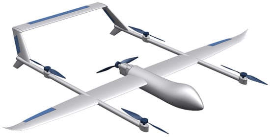
Figure 1.
Hybrid VTOL UAV—Skyhunter from the ACoRUs Project [23].
The advantage of such UAVs is that they can be used in densely built-up areas and small places, as there is no need for a runway. This allows for easier and broader application of UAVs. While individual hybrid VTOL UAVs are capable of performing simple delivery missions, such as medical transports [24], the deployment of UAV swarms is of greater importance for more challenging mission objectives. This could be monitoring a disaster area [25] or conducting search and rescue missions (SaR-missions). Combining individual and swarm missions is also conceivable in the case of providing a missing person with a first aid kit. In SaR missions, launching UAVs from seagoing vessels combines the interaction of different types of assets, making the use case even more complex [26]. Even though the focus of this work is on the management of a fleet of UAVs through PHM methods, some complexity of the use case is required. To keep this as low as possible, the next section describes how the use case is implemented in the UAV fleet simulation.
2.2. Simulation Use-Case
As described before, there are several possible use cases in which multiple hybrid VTOL UAVs act cooperatively. For simplicity, this work focuses on a maritime SaR mission conducted by a UAV swarm of random size, with additional UAVs conducting an individual mission representing the provision of a first aid kit to one or more missing persons. A program is used to create arbitrary mission configurations. It starts by assigning a mission ID and then randomly decides whether the upcoming mission is a SaR or a delivery mission and adds this to the mission configuration as a binary parameter. While each delivery mission is given a unique ID, the SaR mission configurations have the same ID with respect to the UAVs involved. Next, the mission length is defined. In the case of a delivery mission, the mission length is simply the distance from the origin to the destination. In the case of a SaR mission, the mission length exceeds the capacity of a single UAV as it relates to the search pattern that must be flown within the mission over the area of interest. In addition, a random distance is added for the approach, representing different distances between the area of interest and different heliports on the coast line. Another parameter needed for detailed mission generation is the number of UAVs involved. In the case of a delivery mission, it is always a single UAV, while in the case of a SaR-mission, the number of UAVs depends on the overall length of the mission and the search pattern that needs to be flown over the area of interest. In the case of a SaR mission, two to four UAVs are involved. This information is stored in a csv file so that it is the same for multiple experiments. They also serve as input to the mission generation program, which will be described in the next section.
2.3. Simulation Framework Overview
In addition to the mission queue, there are several other software modules that enable the processing of pending missions, the deployment of the UAVs, and the storage of historical usage data. The entire simulation framework can be seen in Figure 2. The simulation is implemented in Python, with the threading package [27] playing an important role in enabling parallel degradation simulation of multiple UAVs. The whole simulation can be divided into two parts. The main part is responsible for the deployment strategy and is shown in the upper part of Figure 2. It is connected to the lower part of Figure 2, which is responsible for the mission execution and degradation modeling. All data generated during mission execution is stored in a database so that historical data is available to implement machine learning models later. Each part of the simulation is described in more detail in the following sections.
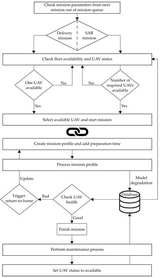
Figure 2.
Flowchart.
2.4. Mission Generation
After the mission queue has been created, each configuration can be translated into detailed mission profiles. As described earlier, the mission profiles differ between a delivery-mission and a SaR-mission. The mission profile for a delivery mission consists of a takeoff and landing phase connected by a fixed-wing flight from the takeoff point to the destination. A typical mission profile for a delivery-mission can be seen in Figure 3.
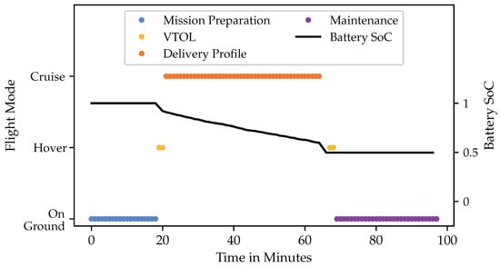
Figure 3.
Delivery mission profile with different mission phases and energy consumption.
The SaR mission profile is more complex. It contains the same takeoff and landing phase, but after take-off and before landing, there is a fixed-wing flight to reach the area of interest. Within this area, the UAV alternates between fixed-wing and hover flight to represent a more exploratory flight during the search. A typical mission profile for a SaR mission can be seen in Figure 4.
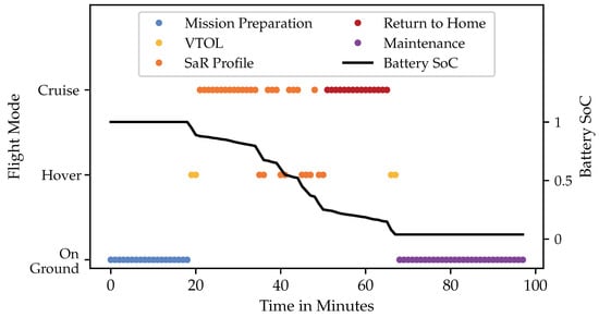
Figure 4.
Search and rescue mission profile with different mission phases and energy consumption.
Depending on the mission type, the UAV is deployed differently, resulting in different degradation, which is described in more detail in the next section. Another important aspect of mission generation is that it allows the mission to be executed in real-time. This means that for each specified interval, an observation of the UAV is made, regardless of whether it is in fixed-wing or hover mode. In addition, other values are stored in the database, such as the health values of the subsystem’s components. The real-time capability is based on the definition of soft real-time given by [28]. The performance of the real-time data storage is described in Section 4.1, the additional mission phases in Section 2.6, while the energy consumption is described in Section 2.5. It can be concluded that the mission execution can be observed in equidistant time steps to meet real-time requirements, and that usage differs between delivery missions and SaR mission, which also results in different energy consumption and degradation.
2.5. UAV Model with Degradation
The main objective of the UAV model is to describe the degradation of mission critical subsystems in real-time. The selection falls on the following subsystems:
- Pusher motor: The pusher motor is responsible for energy-efficient fixed-wing flight. If it is defective, the distances required by the mission profiles can no longer be achieved.
- Hover motor: The hover motor is responsible for the VTOL capability, which is defined as a key component for the selected mission scenarios.
- Battery: The battery is responsible for providing sufficient energy to operate the UAV. The discharge rate depends on the state of the previously mentioned subsystems.
A UAV is simplified from a pusher motor, four hover motors and one battery. A bearing failure and a winding short circuit are implemented for both motor types. The difference is that the pusher motor is assumed to be more robust compared to a hover motor due to its larger size. Therefore, the degradation of a hover motor is faster than that of the pusher motor. The battery shows two time-dependent processes. One of these processes is the discharge rate. Depending on the use of the drone, the discharge rate can be higher or lower. Using all four hover motors results in a high discharge rate, while using only the single pusher motor results in a lower discharge rate. This behavior can be seen in Figure 3 and Figure 4, where the discharge over time is represented by the black curve. The second time-dependent process is the reduction in battery capacity during recharge between missions. This degradation process is described in [29] as well as in [30] and is assumed in this work to be a linear process, depending on the charge-cycles. Motor wear has an impact on energy consumption. A motor with higher degradation is not as powerful as a healthy motor, so more energy needs to be drawn from the battery to achieve the same performance. This allows for constant flight performance of the UAV while maintaining inter-dependencies between subsystems. This highlights the focus of this work, which is on subsystem degradation and the application of PHM methods. Both the health initialization (due to manufacturing variation) and the degradation process of the different components are subject to randomization so that a more realistic progression can be modeled. In the case of the winding failure in one of the hover motors, the progression of degradation can be seen 52 times in Figure 5.
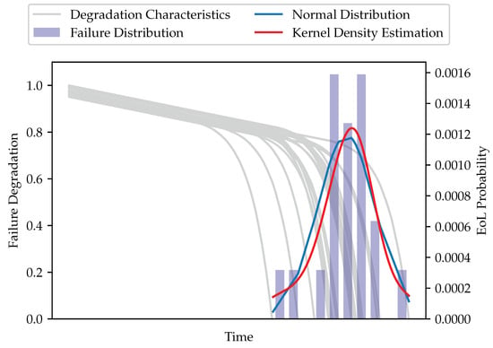
Figure 5.
Degradation progression and failure distribution of hover coil failure.
The gray slopes show the time course of the degradation. To avoid confusion between simulation time and actual time, the exact indication of the time unit on the x-axis has been removed. The course of degradation corresponds to the degradation process required for the implementation of PHM methods, as described in [31]. The degradation process begins with a healthy system (Health = 1), and the initial degradation is subject to some randomization to account for differences in manufacturing. In addition, degradation begins with a linear progression until a fault occurs in the component. Thereafter, the degradation is exponential and decreases to a health of 0 where the component can no longer be used.
The integrated bar chart shows the distribution of failures, the blue curve shows the normal distribution of failures, the red curve shows the Kernel Density Estimate of failures. While the normal distribution is based on statistical values drawn from the data, the kernel density estimation is fitted to the actual data. It is beneficial to see that both slopes have the same characteristics, which is a validation of the realistic distribution of the failures. A closer look at the degradation process reveals a linear trend at first (wear phenomena), which is continued from a point in time (fault occurrence) with an exponential course. Other failure types show the same characteristics. The difference is the timing of the failure occurrence. Again, it is assumed that the pusher motor is more robust, so the mean value for the occurrence of failure is higher compared to the occurrence of failures of the hover motor. A bearing failure is assumed to occur more frequently than a winding short—therefore, the time of occurrence of bearing failure is much shorter than that of a winding short. The combination of different failure characteristics creates a complex degradation process for the higher-level system, the UAV itself.
To meet the requirements of the simulation, the UAV model must be deployed such that degradation is applied incrementally (in real-time) to each UAV instance during mission execution. In the case of swarm missions, multiple UAV instances are deployed simultaneously.
2.6. UAV Deployment and Mission Execution
The main program of the simulation processes the mission queue by assigning the available UAVs to the upcoming missions. To check the current status of the UAVs, the main program interacts with a database. In addition to availability, health data can be queried to provide a robust assignment. To launch a delivery mission, only one UAV must be available. For SaR missions, multiple UAVs must be available to launch the mission simultaneously. When the available UAV is selected, it starts its mission. According to the Figure 3 and Figure 4, a mission consists of the following three phases:
- Mission preparation: The UAV needs must be prepared, e.g., by installing the necessary equipment, performing checks, etc.
- Mission execution: Execution of the generated mission profile beginning and ending with a VTOL phase. Due to the high fixed-wing portion of delivery missions, the energy consumption is not that high and the battery capacity will always provide enough energy for the mission. Due to the hover portion of SaR missions and the randomness of energy consumption, as well as the effects of degradation on energy consumption, battery capacity can be critical for SaR missions. To ensure safe operation, the mission is aborted at a certain capacity threshold so that the UAV can still fly to the next base with sufficient battery capacity to perform a safe landing. Neglecting exact distances, the return-to-home process is modeled rather generically.
- Maintenance: After each flight, each UAV is serviced. Maintenance includes several steps, starting with a minimal maintenance procedure in the form of a battery replacement to prepare the UAV for its next mission. Depending on the maintenance strategy chosen and the degradation of the subsystems, other steps may also be included. For each type of fault, there is a corresponding maintenance procedure with an average maintenance time. If multiple faults are identified and maintenance is triggered for them, the processes are not performed sequentially but in parallel, i.e., the longest maintenance procedure determines the downtime of the UAV. After maintenance is completed, the status of the UAV is set back to “available” and it is ready for the next mission.
All equidistant steps of the mission execution are used to store usage and degradation data in a database for later use in PHM algorithm development. Failure data is generated across multiple missions with different remaining useful lives (RUL) each time due to different failure constellations. An example of a typical failure constellation is shown in Figure 6:
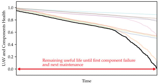
Figure 6.
Fault constellation of one UAV with its subsystems.
The diagram shows the degradation of the UAV over time. To avoid confusion between simulation time and actual time, the exact indication of the time unit on the x-axis has been removed. Black represents the system state derived from the most degraded component. The colored curves represent the individual state of the components. As mentioned earlier, the degradation characteristics of the different subsystems differ from each other. There are components with more constant degradation and components where failure occurs more suddenly. The combination of the different degradation characteristics of the components leads to unique RUL time intervals. Different maintenance strategies can be used to manipulate the time intervals between maintenance events. This paper mainly focuses on a predetermined and a condition-based maintenance (CBM) strategy. The results and differences are described in Section 3 and Section 4.
3. Simulation and Application of Maintenance Strategies
The simulation is run over the number of missions listed in the mission queue. For each experiment, the mission queue is the same, ensuring high comparability of results. The program generates 10,000 missions consisting of 8022 delivery and 1978 SaR missions. Since SaR missions include multiple individual missions (totaling 7955 individual missions), the total number of missions executed increases to 15,977. As a result, about the same number of delivery and SaR-missions are executed.
Several experiments with different maintenance strategies have been conducted. Starting from a run-to-failure approach as a basis, further implementations are a predetermined maintenance strategy and a condition-based maintenance strategy. Detailed descriptions of the strategies follow in the next subsection. During the experiment, several key performance parameters were used to evaluate the performance of the different maintenance strategies. A comparison of the results is given in Section 4.
3.1. Run-to-Failure Approach
A run-to-failure approach is used as a basis and to develop subsequent strategies. In this approach, a component is used until the health state of this component reaches zero. Exactly after the mission at which the health state falls below the threshold, a maintenance operation is performed on that specific component. This allows validation of the occurrence of failures (compare with Figure 5), derivation of maintenance intervals for the predetermined maintenance strategy, and gives a first impression about the functionality of the simulation.
3.2. Predetermined Maintenance Strategy
Based on the run-to-failure data from the previous approach, a fixed maintenance interval can be derived. To avoid sudden failures of individual components, a safety margin is added. Since the failure progression is implemented with some degree of randomness, failures occur at different times. The earliest failure from the run-to-failure approach is an indicator of the maintenance interval for a specific component. The safety margin, which shortens the maintenance interval, is an additional measure. The predetermined maintenance strategy does not take into account any knowledge about the condition or health of the UAV, and maintenance is performed in fixed intervals. To make it more realistic and comparable, a maintenance operation is assumed to be a health check of the whole UAV. Thus, if a component already shows severe degradation, the maintenance personnel will identify other faulty components and replace them as part of the maintenance procedure. Based on an assumed visual inspection, this is done for components that are close to failure. This prevents maintenance work from being carried out at very short intervals, which would drive up downtime in an unrealistic manner.
3.3. CBM Strategy
The condition-based maintenance strategy takes into account real-time health information from each UAV. On the one hand, this information is used to initiate maintenance procedures, on the other hand, it is used to assign suitable UAV for upcoming missions in order to extend maintenance intervals.
Maintenance procedures are not initiated by a fixed time interval, but by a threshold for the condition of the UAVs’ components. Like predetermined maintenance, condition based maintenance is assumed to be a complete UAV check. However, health information is used to identify components that have already experienced faults in an early state. Depending on the performance of the fault diagnosis module, fault detection can be assumed to be delayed. As a first approach in this work, fault detection is assumed to be ideal. A maintenance procedure then consists of maintaining the component that has fallen below the maintenance threshold, as well as all components where a fault has been detected.
Of course, smarter maintenance scheduling could lead to better results, but as a first approach and to show the effectiveness of this simulation, the above strategies lead to promising results, which are discussed in the next section.
4. Results
The simulation is reviewed and evaluated with respect to two functionalities. First, the real-time capability is evaluated based on the time intervals of the entries in the database. The results can be found in the next section. Second, the manipulation of maintenance key parameters by different maintenance strategies is evaluated. The results can be found in the subsequent section.
4.1. Validation of Real-Time Capability
According to [28], the basic definition of real-time is that a technical process is recorded with the help of a computer system. The system is divided into an external system, which specifies the temporal conditions and an internal system, which observes the temporal condition. Furthermore, real-time is differentiated between soft and hard real-time. While soft real-time tolerates deviations from the specified time condition, hard real-time does not tolerate any violation of the specified time condition. In avionics, real-time is described in more detail by the ARINC653 and ARINC644 standards. The former standard talks about partitioning, where each process is cyclically assigned a fixed time step. The second standard deals with deterministic transmission times between control systems.
To dive deeper into the real-time capability of the simulation, the database entries were statistically evaluated by calculating the mean and the standard deviation of the entries. The simulation system presented in this work fits the properties of real-time described in the literature as follows:
- The external time condition was set to be an observation of the entire fleet every minute in reality, which corresponds to a time interval of 0.05 s in the accelerated simulation environment.
- The system operates in more of a soft real-time environment, as the database entries do not strictly adhere to the specified timing (see Figure 6). The deviation from the given time constraint is small and does not affect the functionality of the simulation. The figure shows that almost every entry in the database is slightly delayed (blue dots) compared to the given time condition. Nevertheless, there are database entries that have a larger deviation from the default time condition. These entries are not within the standard deviation from the given time constraint for the simulation (orange dots) and account for just under 14 percent of the entries in terms of volume, which is negligible compared to the given functionality of the simulation.
- The ARINC653 and ARINC644 standards are met to a small extend. The predefined time condition is comparable to a cyclically occurring fixed time step, which is met almost exactly. The communication between the systems of the simulation (checking the UAV availability of the fleet) is done with a given time condition, so there is a deterministic transmission time regarding the communication of the models within the simulation.
An important feature of the simulation is that the status is stored in the database during mission execution and not only between missions. Thus, component degradation during mission execution is visible and can be matched with UAV usage, which is an important feature for algorithm development and PHM method application. In addition, the UAV mission can be manipulated during mission, e.g., by changing the waypoints or flight mode, to alter the UAV usage and degradation accordingly.
A program that checks the time differences of the database entries allows the visualization of the real-time capability of the simulation, as shown in Figure 7:
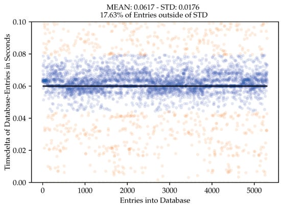
Figure 7.
Real-time capability observed through time differences of data entries into database.
The figure shows the given time condition in black; the database entries within the standard deviation are shown in blue and the entries outside the standard deviation in orange. The figure displays the database entries for the complete processing of a mission queue of one single UAV.
4.2. Impact of Different Maintenance Strategies
To test the simulation in terms of applicability of PHM methods, the predetermined and condition-based maintenance strategies mentioned in Section 3 were integrated. Intelligent maintenance strategies should impact at least one of the key parameters of time, quality or cost of service. Two metrics have been developed to compare the different maintenance strategies. Metric one is given in the following equation:
The metric relates the total mission time, consisting of the time in delivery deployment () and time in SaR deployment (), and the time the UAV is not in deployment or maintenance (). The goal of this metric is to show whether the UAV fleet is being used efficiently. For example, it would be beneficial to deploy more UAVs on a SaR mission, if available, and complete the mission earlier. This would have a beneficial effect on the key parameter of time, but could have a detrimental effect on the key parameter cost.
The second metric is given by the equation:
This metric looks very similar to metric in Equation (1), but relates total deployment time () to maintenance time and thus focuses more on efficient use of the fleet. If the maintenance time is delayed, e.g., by properly deploying UAVs to a suitable mission profile, and subsystem degradation is reduced, maintenance intervals will increase and the value for should increase.
Both metrics are simple, but lead to different results in evaluating the performance of the applied maintenance strategy. They are used for both the predetermined maintenance experiment and the condition-based maintenance experiment.
Evaluation of Predetermined and CBM Experiment
Using the given metrics (1) and (2), the experiments were evaluated with a predetermined maintenance strategy as well as with a condition-based maintenance strategy. Missions from the mission queue were evenly distributed across the fleet so that mission dwell times were nearly equal across all UAVs. Figure 8 shows the dwell times of each UAV within the fleet for each mission phase for an experiment with a predetermined maintenance strategy.
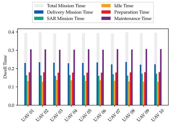
Figure 8.
Evaluation of fleet usage with a predetermined maintenance strategy.
While UAVs are deployed randomly in the predetermined strategy, the CBM strategy selects UAVs by choosing an appropriate UAV for an upcoming mission with respect to the upcoming load profile. An UAV with a worn pusher motor is preferably no longer used for delivery missions, since the use of the pusher motor is predominant in such missions. Since the bar chart from the predetermined maintenance experiment looks almost exactly the same, this figure is not shown. However, the differences are illustrated by the results in the evaluation metrics. For the predetermined experiment, is 3.012 and takes a value of 1.351. For the CBM experiment, is about 3.018 and takes a value of 1.379.
When the metrics yield larger values, better performance is achieved in terms of fleet utilization and maintenance. It could be concluded that the CBM strategy performs better compared to the predetermined maintenance strategy due to higher values. However, due to the marginal difference and randomization in the degradation modeling and other parts of the simulation, the results may look different between experiments. Therefore, the simulation for each maintenance strategy was run thirty times with the same parameters to obtain reliable results. The normal distributions of the metrics are shown in Figure 9.
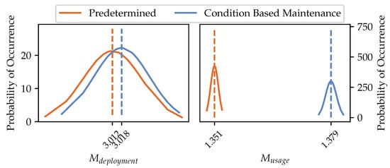
Figure 9.
Normal distribution of evaluation results for ten predetermined maintenance experiments and ten condition-based maintenance intervals.
For , the mean values of the predetermined and the CBM strategy are quite close to each other. The distribution of the values of the predetermined maintenance strategy is almost the same compared to the distribution of the CBM strategy. The small difference in the mean values can be explained by the similar deployment strategy of the UAVs. Improvements could be achieved by changing the deployment strategy, e.g., by integrating unused UAVs. More UAVs could be used for a SaR mission if the next missions cannot be launched due to a lack of available UAV. This would result in a faster mission execution and higher utilization of available UAVs. However, it is questionable whether there will always be outstanding missions in reality. More UAVs deployed for a SaR mission means faster mission completion on the one hand, but higher costs on the other. Cost is not directly accounted for in this metric. The distributions of can be better distinguished from each other. The dispersion looks very similar again, but the mean values of the distributions are clearly separated between the two maintenance strategies. This suggests that the enhanced maintenance strategies using PHM methods are having their desired effect. Checking the UAV status before deployment, deploying for the most appropriate mission, and initiating maintenance actions depending on the condition of the components lead to less degradation and maintenance actions. This would also reduce the cost in an indirect way, which again cannot be directly captured by this metric.
Of course, more complex metrics are possible, but the metrics presented are intended to illustrate that the simulation allows the observation of various performance parameters. Depending on the desired outcome, additional metrics can be developed to review and improve the utilization of the UAV fleet.
Due to the randomization of the initialization and the degradation processes within the simulation, the execution of multiple simulation runs produces results that are also subject to a certain degree of randomness. These simulations are also referred to as Monte Carlo simulations [32]. To prove that the simulation produces robust results, the means and standard deviations (STD) for the metrics that evaluate the Monte Carlo simulation are investigated over the number of experiments. The progression of the statistical values can be seen in Figure 10 and Figure 11.
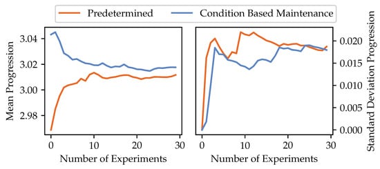
Figure 10.
Progression of mean and standard deviation over the number of simulation runs for .
The figure shows that the mean value for becomes stable after about 12 simulation runs. The mean values of the predetermined and the CBM simulations converge. The STD becomes stable at about 20 simulation runs and a convergence of the STD for the two maintenance strategies can be observed again.
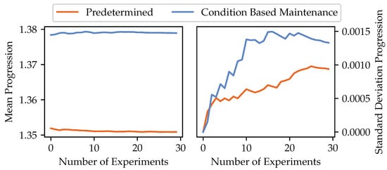
Figure 11.
Progression of mean and standard deviation over the number of simulation runs for .
For , the mean becomes stable after about 5 simulation runs. The STD is not stable after 20 simulation runs, but the value for the STD is pretty low. These values are assumed to converge with further simulation runs, leading to comparable normal distributions in Figure 9. The development of the statistical values over the number of experiments carried out confirms the results in Figure 9 and thus a stable run and the usefulness of the simulation itself. The section also addressed the real-time capability of the simulation, which can be verified by transferring data from the simulation to the database. In conclusion, the simulation meets the desired requirements and can be used to test and compare different PHM methods and maintenance strategies.
5. Conclusions and Future Work
This work describes the design of a simulation framework that maps the wear and tear of individual UAVs in a fleet for simplified mission profiles. Changes in UAV status and health due to degradation processes are captured at fixed time intervals during their specific use for mission execution. These degradation effects are partially interdependent and affect UAV performance parameters. The simulation enables the implementation of different mission deployment and maintenance strategies to influence the performance of the UAVs, which affects the availability of the assets.
It is shown that the simulation is observable in two different ways. The real-time performance is measurable by the input times of the UAV status in the connected database. An initial evaluation shows that the simulation is operating at an acceptable level of real-time performance. Improvements to the implementation could increase the performance of the simulation. In addition, it is possible to evaluate the deployment and maintenance strategy with metrics. The goal is to increase the fleet utilization in terms of cost, time and quality. While the implementation of simple metrics does not directly measure costs, a CBM maintenance strategy can be expected to decrease costs due to fewer maintenance operations. This demonstrates the ability to impact UAV utilization through various operational and maintenance strategies. The more complicated the mission becomes, the more precise the metrics must be designed to verify the desired target parameters.
In the future, more complex mission scenarios will be integrated into the simulation. These will include 2D waypoints so that distances can be taken into account during mission execution. It is conceivable that the return-to-home function will not be triggered due to a battery threshold, but distances to possible heliports will be taken into account. A 2D extension also allows the consideration of weather effects, such as wind, on the UAVs’ performance. In addition, focus should be placed on health-related swarm management during missions to benefit more from the real-time capability of the simulation. To further approximate the presented methodology to reality, it would be necessary to replace the generic degradation models with degradation models based on experimental data. The modular structure of the simulation favors the inclusion of different models, so that the effectiveness of different maintenance strategies could also be evaluated on real degradation models.
Funding
This research is part of the RTAPHM research project funded by the Federal Aeronautical Research Programme of the German Federal Ministry for Economic Affairs and Climate Action (grant number 20X1736L). The APC was funded by the Technical University of Darmstadt.
Data Availability Statement
The simulation frameworks presented in this study are openly available in the TUdatalib repository at https://tudatalib.ulb.tu-darmstadt.de/handle/tudatalib/3680 (accessed on 16 December 2022).
Acknowledgments
The author acknowledges support by the Deutsche Forschungsgemeinschaft (DFG—German Research Foundation) and the Open Access Publishing Fund of the Technical University of Darmstadt.
Conflicts of Interest
The author declares no conflict of interest. The funders had no role in the design of the study; in the collection, analyses, or interpretation of data; in the writing of the manuscript, or in the decision to publish the results.
Abbreviations
The following abbreviations are used in this manuscript:
| ARINC | Aeronautical Radio Incorporated |
| BLDC | Brush-less Direct-current |
| CBM | Condition Based Maintenance |
| Del | Delivery |
| EoL | End of Life |
| ESC | Electronic Speed Controller |
| PHM | Prognostics and Health Management |
| RUL | Remaining Useful Life |
| SaR | Search and Rescue |
| SoC | State of Charge |
| SoS | System of Systems |
| STD | Standard Deviation |
| UAV | Unmanned Aerial Vehicle |
| VTOL | Vertical Take-off and Landing |
References
- Shakhatreh, H.; Sawalmeh, A.H.; Al-Fuqaha, A.; Dou, Z.; Almaita, E.; Khalil, I.; Othman, N.S.; Khreishah, A.; Guizani, M. Unmanned Aerial Vehicles (UAVs): A Survey on Civil Applications and Key Research Challenges. IEEE Access 2019, 7, 48572–48634. [Google Scholar] [CrossRef]
- Myjak, M.V.K.; Ranganathan, P. Unmanned Aerial System (UAS) Swarm Design, Flight Patterns, Communication Type, Applications, and Recommendations. In Proceedings of the 2022 IEEE International Conference on Electro Information Technology (eIT), Mankato, MN, USA, 19–21 May 2022; pp. 586–594. [Google Scholar] [CrossRef]
- Federal Aviation Administration. Aerospace Forecast Fiscal Years 2022–2042. Available online: https://www.faa.gov/sites/faa.gov/files/2022-06/FAA_Aerospace_Forecasts_FY_2022-2042.pdf (accessed on 24 October 2022).
- Dingeldein, L. UAV Fleet Simulation (Version 0). 2022. Available online: https://tudatalib.ulb.tu-darmstadt.de/handle/tudatalib/3680 (accessed on 27 December 2022).
- Zadeh, S.M.; Yazdani, A.; Elmi, A.; Abbasi, A.; Ghanooni, P. Exploiting a Fleet of UAVs for Monitoring and Data Acquisition of a Distributed Sensor Network. Neural Comput. Appl. 2022, 34, 5041–5054. [Google Scholar] [CrossRef]
- Alighanbari, M. Task Assignment Algorithms for Teams of UAVs in Dynamic Environments. Master’s Thesis, Massachusetts Institute of Technology, Cambridge, MA, USA, 2004. [Google Scholar]
- Hayat, S.; Yanmaz, E.; Bettstetter, C.; Brown, T.X. Multi-objective drone path planning for search and rescue with quality-of-service requirements. Auton. Robot. 2020, 44, 1183–1198. [Google Scholar] [CrossRef]
- Paixão de Medeiros, I.; Rodrigues, L.R.; Santos, R.; Shiguemori, E.H.; Nascimento Júnior, C.L. PHM-based Multi-UAV task assignment. In Proceedings of the 2014 IEEE International Systems Conference Proceedings, Ottawa, ON, Canada, 31 March–3 April 2014; pp. 42–49. [Google Scholar] [CrossRef]
- Paixão de Medeiros, I.; Ramos Rodrigues, L.; Strottmann Kern, C.; Duarte Coelho dos Santos, R.; Hideiti Shiguemori, E. Integrated task assignment and maintenance recommendation based on system architecture and PHM information for UAVs. In Proceedings of the 2015 Annual IEEE Systems Conference (SysCon) Proceedings, Vancouver, BC, Canada, 13–16 April 2015; pp. 182–188. [Google Scholar] [CrossRef]
- Valenti, M.; Bethke, B.; How, J.P.; de Farias, D.P.; Vian, J. Embedding Health Management into Mission Tasking for UAV Teams. In Proceedings of the 2007 American Control Conference, New York, NY, USA, 9–13 July 2007; pp. 5777–5783. [Google Scholar] [CrossRef]
- Radzki, G.; Bocewicz, G.; Golińska-Dawson, P.; Jasiulewicz-Kaczmarek, M.; Witczak, M.; Banaszak, Z. Periodic planning of UAVs’ fleet mission with the uncertainty of travel parameters. In Proceedings of the 2021 IEEE International Conference on Fuzzy Systems (FUZZ-IEEE), Luxembourg, 11–14 July 2021; pp. 1–8. [Google Scholar] [CrossRef]
- Radzki, G.; Golińska-Dawson, P.; Bocewicz, G.; Banaszak, Z. Modelling Robust Delivery Scenarios for a Fleet of Unmanned Aerial Vehicles in Disaster Relief Missions. J. Intell. Robot. Syst. 2021, 103, 63. [Google Scholar] [CrossRef]
- Bouzidi, Z.; Terrissa, L.S.; Zerhouni, N.; Ayad, S. QoS of cloud prognostic system Application to aircraft engines fleet. Eur. J. Ind. Eng. 2020, 14, 34–57. [Google Scholar] [CrossRef]
- Deng, Q.; Santos, B.; Verhagen, W. A Novel Decision Support System for Optimizing Aircraft Maintenance Check Schedule and Task Allocation. Decis. Support Syst. 2021, 146, 113545. [Google Scholar] [CrossRef]
- Andrade, P.; Silva, C.; Ribeiro, B.; Santos, B.F. Aircraft Maintenance Check Scheduling Using Reinforcement Learning. Aerospace 2021, 8, 113. [Google Scholar] [CrossRef]
- Corbetta, M.; Banerjee, P.; Okolo, W.; Gorospe, G.; Luchinsky, D. Real-time UAV Trajectory Prediction for Safety Monitoring in Low-Altitude Airspace. In Aiaa Aviation 2019 Forum; Aerospace Research Central: Dallas, TX, USA, 2019. [Google Scholar] [CrossRef]
- Darrah, T.; Quiñones-Grueiro, M.; Biswas, G.; Kulkarni, C.S. Prognostics Based Decision Making for Safe and Optimal UAV Operations. In Aiaa Aviation 2021 Forum; Aerospace Research Central: Dallas, TX, USA, 2021; p. 394. [Google Scholar] [CrossRef]
- Corbetta, M.; Kulkarni, C.; Banerjee, P.; Robinson, E. Uncertainty Quantification Framework for Autonomous System Tracking and Health Monitoring. Int. J. Progn. Health Manag. 2021, 12. [Google Scholar] [CrossRef]
- Heier, H.; Mehringskötter, S.; Preusche, C. The use of PHM for a dynamic reliability assessment. In Proceedings of the 2018 IEEE Aerospace Conference, Big Sky, MT, USA, 3–10 March 2018; pp. 1–10. [Google Scholar] [CrossRef]
- Zhang, H.; Song, B.; Li, F.; Xuan, J. Multidisciplinary design optimization of an electric propulsion system of a hybrid UAV considering wind disturbance rejection capability in the quadrotor mode. Aerosp. Sci. Technol. 2020, 110, 106372. [Google Scholar] [CrossRef]
- Andersson, K.; Bang, M.; Marcus, C.; Persson, B.; Sturesson, P.; Jensen, E.; Hult, G. Military utility: A proposed concept to support decision-making. Technol. Soc. 2015, 43, 23–32. [Google Scholar] [CrossRef]
- Zong, J.; Zhu, B.; Hou, Z.; Yang, X.; Zhai, J. Evaluation and Comparison of Hybrid Wing VTOL UAV with Four Different Electric Propulsion Systems. Aerospace 2021, 8, 256. [Google Scholar] [CrossRef]
- Prochazka, F. Fehlertolerante Regelung üBeraktuierter Unbemannter Flugsysteme; Internal Report; TU Darmstadt: Darmstadt, Germany, 2017. [Google Scholar]
- Sambodo, F.A.; Wahyanto, W.; Wijaya, M.; Mustofa, G.H.; Isrinanto, M.F.A.F.; Arifianto, O. Preliminary design of dual-system hybrid VTOL UAV for medical delivery purpose. AIP Conf. Proc. 2021, 2366, 030007. [Google Scholar] [CrossRef]
- Gabbert, B. Hybrid Rotor/Fixed Wing Drone was Used Extensively over SCHNEIDER SPRINGS FIRE. Available online: https://fireaviation.com/2021/10/29/hybrid-rotor-fixed-wing-drone-was-used-extensively-over-schneider-springs-fire/ (accessed on 25 October 2022).
- Eye, H. Applications of Unmanned Helicopter Systems. Available online: https://www.higheye.com/applications-and-missions/ (accessed on 25 October 2022).
- Python Core Team. Python Threading: Thread-Based Parallelism. 2022. Available online: https://docs.python.org/3/library/threading.html (accessed on 27 December 2022).
- Zöbel, D. Echtzeitsysteme; Springer Vieweg: Berlin/Heidelberg, Germany, 2020. [Google Scholar] [CrossRef]
- Ungurean, L.; Carstoiu, G.; Micea, M.; Groza, V. Battery state of health estimation: A structured review of models, methods and commercial devices. Int. J. Energy Res. 2016, 41, 151–181. [Google Scholar] [CrossRef]
- Azis, N.; Joelianto, E.; Widyotriatmo, A. State of Charge (SoC) and State of Health (SoH) Estimation of Lithium-Ion Battery Using Dual Extended Kalman Filter Based on Polynomial Battery Model. In Proceedings of the 2019 6th International Conference on Instrumentation, Control, and Automation (ICA), Bandung, Indonesia, 31 July–2 August 2019; pp. 88–93. [Google Scholar] [CrossRef]
- Kim, N.; An, D.; Choi, J.H. Prognostics and Health Management of Engineering Systems; Springer: Cham, Switzerland, 2017; pp. 25–28. [Google Scholar] [CrossRef]
- Müller-Gronbach, T.; Novak, E.; Ritter, K. Monte Carlo-Algorithmen; Springer: New York, NY, USA, 2012. [Google Scholar]
Disclaimer/Publisher’s Note: The statements, opinions and data contained in all publications are solely those of the individual author(s) and contributor(s) and not of MDPI and/or the editor(s). MDPI and/or the editor(s) disclaim responsibility for any injury to people or property resulting from any ideas, methods, instructions or products referred to in the content. |
© 2023 by the author. Licensee MDPI, Basel, Switzerland. This article is an open access article distributed under the terms and conditions of the Creative Commons Attribution (CC BY) license (https://creativecommons.org/licenses/by/4.0/).