Article

On the Aeroelasticity of the Active Span and Passive Pitching Polymorphing Wing: Effect of Morphing Rate

1
Department of Aerospace Engineering, Khalifa University, Abu Dhabi 127788, United Arab Emirates
2
Khalifa University Robotics Institute, Khalifa University, Abu Dhabi 127788, United Arab Emirates
*
Author to whom correspondence should be addressed.
Aerospace 2023, 10(1), 57; https://doi.org/10.3390/aerospace10010057
Submission received: 15 November 2022 / Revised: 27 December 2022 / Accepted: 28 December 2022 / Published: 5 January 2023
(This article belongs to the Special Issue Aeroelasticity: Recent Advances and Challenges)

Abstract

:
This paper studies the effect of morphing rate on the aeroelasticity of a polymorphing wing capable of active span extension and passive twist/pitch. A variable domain size finite element model is developed to capture the dynamic effects due to the presence of a variable span in the Euler–Bernoulli beam model, which introduces a structural damping term in the equations of motion. The effect of various morphing rates on the aeroelastic boundaries of the system, namely, flutter velocity and flutter frequency, is examined for a beam undergoing span extension and retraction, from baseline span to 25% span extension and vice versa, respectively. Three points of interest are analyzed: at the start of the span morphing, at the mid-point of morphing, and just before the morphing process ends. The parametric analysis is carried out to determine the effect of varying critical parameters, such as the elastic axis location of the outboard wing section and adjoining spring torsional rigidity on the aeroelastic boundaries of the polymorphing wing.

1. Introduction

Morphing wing technologies offer the potential for unfolding superior aircraft performance by reaping the advantages offered by changes in size and shape that subsequently affect the structural and aerodynamic properties of the system; rendering it suitable to perform effectively over a range of flight conditions in comparison to a fixed-wing conventional aircraft, which can only be optimized for a specific mission profile. Over the years, considerable research has been conducted on morphing wing aircraft by introducing wing camber, thickness, twist, sweep, chord, and span. The reader is referred to [1,2,3] for detailed information regarding morphing types, their properties, and mechanisms. The ability to manipulate shape and size enables the aircraft to be utilized concurrently for various flight conditions, such as a higher aspect ratio for improved endurance and a shorter aspect ratio for greater maneuverability, which would otherwise pose contradictory design conditions on a conventional aircraft. Morphing aircraft can truly result in the conception of multi-role, multi-mission capable aircraft, and they are poised to play a significant role in enhancing the flight performance of future aircraft by reducing fuel consumption, augmenting endurance, decreasing noise, and lessening carbon footprint; helping the aviation industry achieve future sustainability goals, such as ACARE 2020 and FlightPath2050 [4,5].
Although morphing wings offer numerous benefits over their conventional fixed-wing counterparts, their performance is still limited due to their one-dimensional change in size or shape, known as monomorphing. Furthermore, morphing in one wing property can result in reduced performance in any other aspect due to the ensuing aero-structural interaction. For example, span morphing can improve flight range and endurance; however, such advantages come with a penalty of poor maneuverability and increased root loads on the aircraft structure [6]. Similarly, a twist-morphing wing can reduce root loads by active or passive twisting about fore positions of the elastic axis (ea) on the twisting section; however, this results in reduced aeroelastic flutter velocity of the aircraft [7,8].
An emerging research area is concerning the application of several morphing mechanisms into a single aircraft wing, i.e., a polymorphing wing [3,9], to overcome constraints associated with single-degree-of-freedom morphing. These multi-mission aircraft wings could not only be capable of overcoming the limitations posed by a certain morphing scheme on the aircraft dynamics and aero-structural properties, but also improve flight performance by utilizing the flexibility of operation due to available degrees of freedom and optimizing the aircraft for various situation-dependent dynamic changes. One such effort to design a multi-mission capable wing has been made by Ajaj et al. [10], culminating in the conception of the Active Span and Passive Pitching (ASAPP) wing.
Presently, most of the literature about morphing aircraft has been concerned with the development of morphing mechanisms and their actuation, whereas less attention has been paid to its aeroelastic effects. Aeroelastic properties are significantly affected by morphing type, the actuation mechanism, and morphing rate. Therefore, it is imperative to quantify its aeroelastic consequences to obtain substantial advantages from any morphing scheme. Several studies have been conducted on the aeroelasticity of monomorphing wings [11,12,13,14,15,16]; however, the literature is scarce regarding the aeroelasticity of polymorphing wings. Moreover, no low-fidelity finite elements-based mathematical model has been developed for axially moving Euler–Bernoulli beams that incorporates the effect of beam bending as well as torsion, and no study exists that analyses the effect of morphing rates on the aeroelasticity of polymorphing wings incorporating twist and span morphing, to the author’s best knowledge.
The effect of morphing rate on the dynamic aeroelastic stability, particularly on flutter, has been somewhat documented in the literature [1,14,17]. It has been shown that flutter velocity increases for span extension, rising with an increase in actuation rate, and vice versa for retraction. This means that while the morphing rate will play a role during various flight phases for a multi-role morphing aircraft, the effect would be most pronounced in cases where a high actuation rate is required. One such scenario where this could be applicable is when asymmetric span actuation is required for lateral control of the aircraft. This would require a high actuation rate coupled with an extension on one side of the wing and retraction on the other side of the aircraft. The complex interaction of vibration, structural, and aerodynamic properties that ensue make it essential for the aeroelastic properties of the system to be clearly understood before application. Therefore, it is essential to understand and analyze the effect of the morphing rate on the aeroelastic boundaries of a morphing wing aircraft in the initial design stage.
The paper focuses on the effect of morphing rate on the aeroelastic characteristics of the ASAPP wing, capable of span and twist morphing. For this purpose, a variable domain beam finite element model is developed based on the works of Stylianou and Tabbarok [18,19]. This study extends the previous work on variable-length beams by incorporating the effect of twisting in the Euler–Bernoulli beam model. Therefore, the paper is unique in its attempt to derive a variable domain finite element Euler–Bernoulli beam model which can account for changes in twist along the variable span of the beam. A parametric analysis is conducted to quantify the effect of morphing rate on the aeroelastic phenomena of flutter for various elastic axis positions of the outboard wing, and torsional rigidities of the spring adjoining the inboard and outboard wing sections. The analysis is carried out for three respective positions during the morphing process: just after initiation, at the midpoint, and just before ending. Both effects of span retraction and extension are considered, and their effects on the flutter velocity and flutter frequency are examined.

Active Span Extension and Passive Pitching (ASAPP) Wing

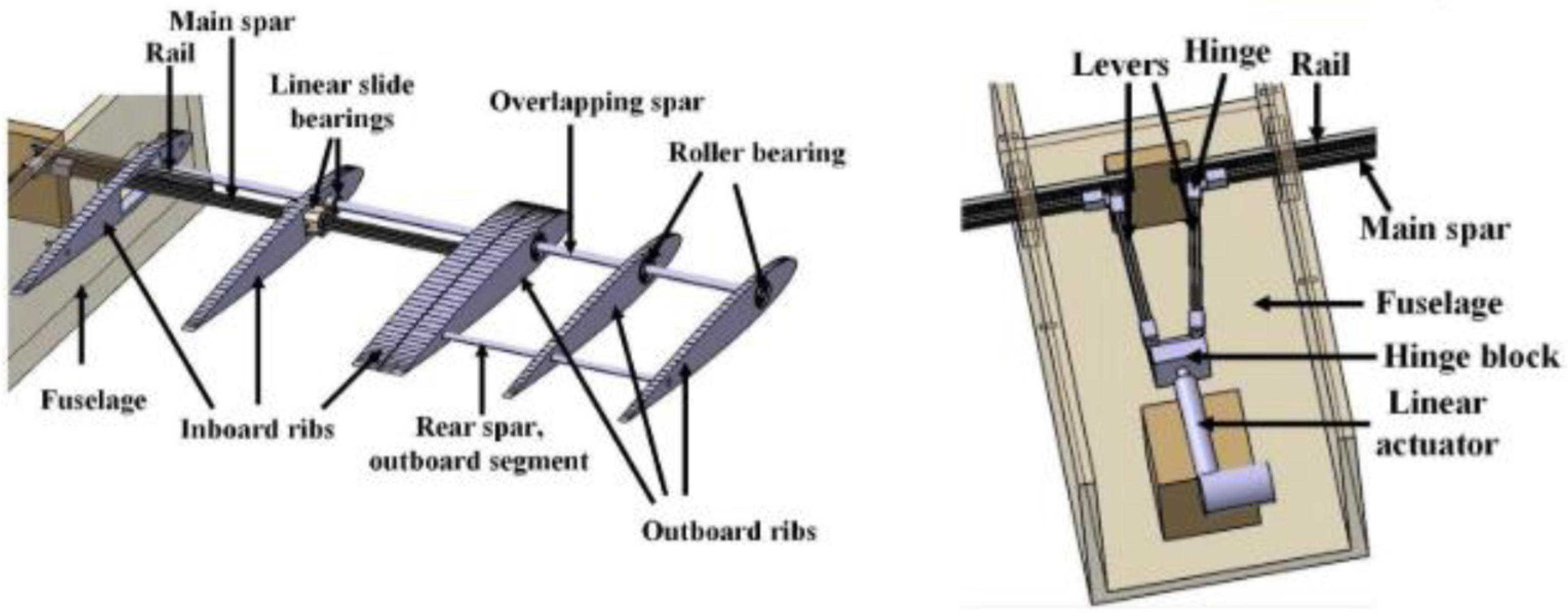
ASAPP wing is a novel wing concept incorporating a two-degrees-of-freedom morphing structure with the wing span divided into two sections, inboard and outboard, connected by an adjoining torsional spring, as shown in Figure 1 and Figure 2. The inboard section is responsible for span morphing due to the extension and retraction movement of the main spar, which is connected to a linear actuator situated inside the fuselage. The twist-morphing outboard section moves passively due to the influence of external loading factors. The elastic axis of the outboard wing section and the adjoining spring are kept ahead of the aerodynamic center, thereby making the passive twisting action oppose any forces that bring about a change in its angle of attack. This leads to a reduction in root bending moment and root shear forces acting on the wing structure. For a detailed insight into the structure, mechanisms, and performance of the ASAPP wing, the reader is recommended to refer to the following study [9,16].

2. Modeling and Validation

2.1. Structural Dynamics Model

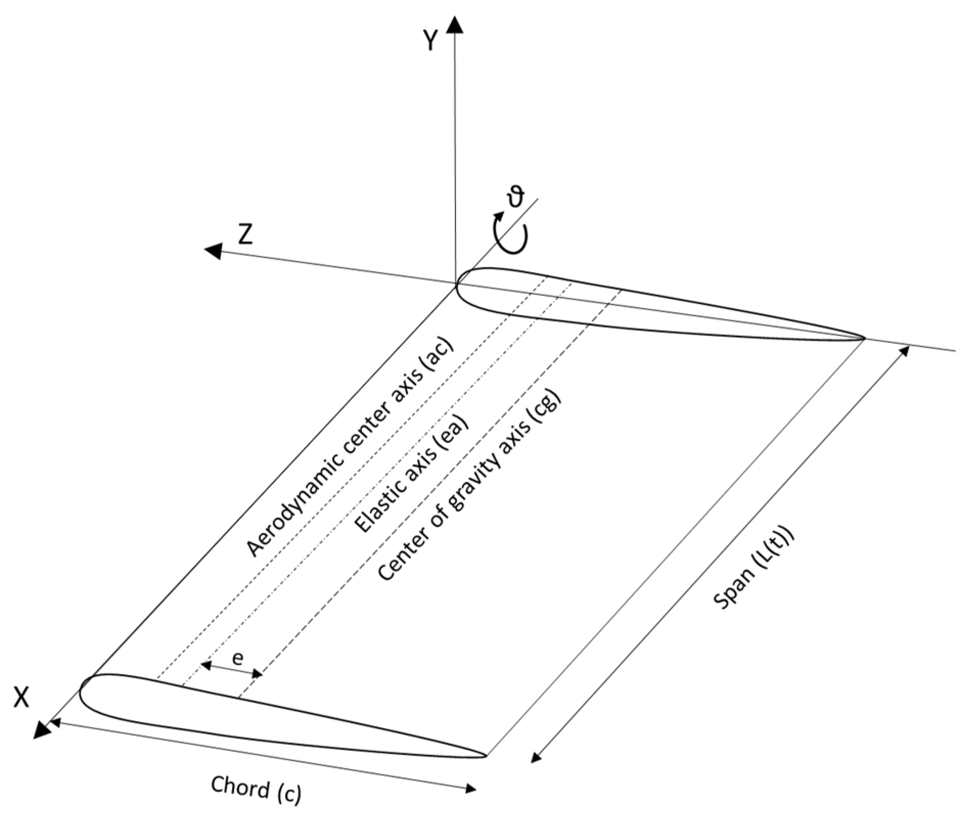
A uniform, rectangular, clean configuration wing (no flaps, slaps, or other high lift devices) is chosen to minimize the underlying effects due to interacting lifting surfaces. The structural dynamics model is developed using an Euler–Bernoulli beam approximation, which is then discretized and solved using a finite element solver on MatlabTM. While it is possible to carry out fixed domain size finite element formulation for time-dependent problems by increasing the number of elements, this approach is not practically feasible as it requires a large number of elements to obtain sufficient smoothness in the solution. This, coupled with an increasing degree of freedom with an increase in total fixed-domain elements, has a considerable toll on the computational power requirements for any case [19]. Therefore, a variable domain size elemental formulation is developed based on the works of Stylianou and Tabarrok [18,19], in which the element size varies with time in a prescribed fashion whilst keeping the total elements number constant. The dynamic axially moving beam model developed by Stylianou and Tabbarok is extended in this study to incorporate the effects of beam torsion, for cases where the shear center and center of mass are not coincident, therefore enabling it to be used to accurately study the bending-torsion wing dynamics and aeroelastic properties for a span-morphing wing. The schematic of a typical wing section is shown in Figure 3.
Using a cantilever Euler–Bernoulli beam approximation, the kinetic energy (T) of the axially moving beam undergoing bending and torsion is defined as:
T   =   m 2 0 L Y t +   X t Y X 2 dX   +   2 e 0 L Y t ϑ t dX +   r α 2 0 L ϑ t + X t ϑ X 2 dX +   m 2 L B L ˙ 2
where Y and   ϑ   are the bending deflection and torsional twist, respectively, in the global coordinate system (GCS), m’ is the mass per unit length, L(t) is the instantaneous length of the beam at time t, LB is the total length of the beam,   L ˙   is the rate of change in length (morphing rate), e is the distance between the center of gravity (cg) and elastic axis (ea), rα is the radius of gyration, and X is the position along the span. The first three terms in Equation (1) represent the kinetic energy due to bending-torsion coupling, and the last term denotes the complementary longitudinal kinetic energy. The potential energy for the system is characterized as:
U   =   EI 2 0 L 2 Y X 2 2 dX + GJ 2 0 L ϑ X 2 dX   0 L m 2 ( L X ) L ¨ Y X 2 dX
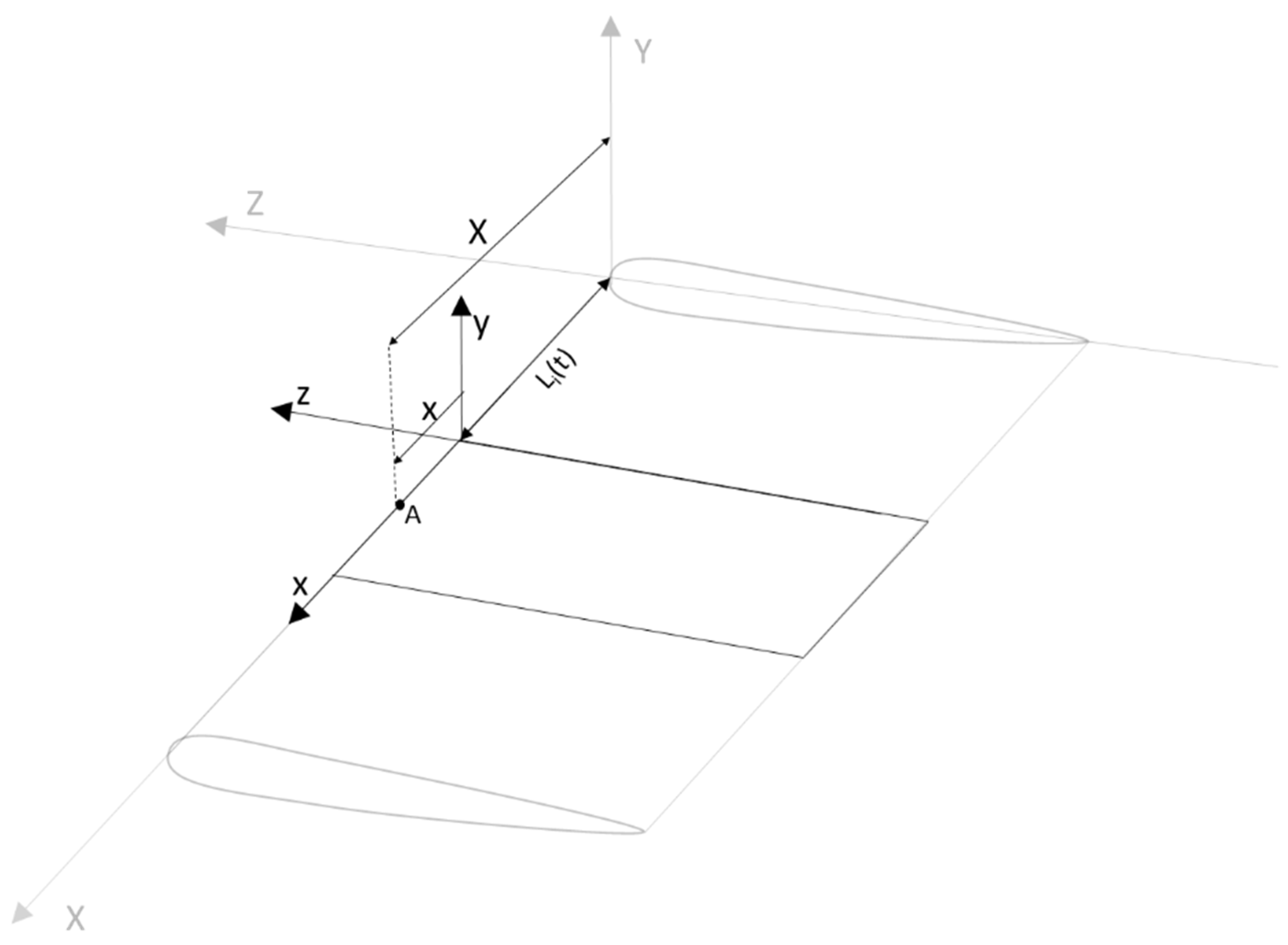
where EI is the bending rigidity of the beam and GJ is torsional rigidity. The first two terms represent the elastic strain energy due to bending and torsional deflection of the beam, whereas the last term denotes the potential energy due to axial loading. In the case of a constant acceleration field, the last term vanishes and is only relevant for the case of force application at the root. The schematic of the variable domain size beam is shown in Figure 4 where Ȳ represents the combined bending and torsion displacement vector.
An assumption of axial rigidity allows the substitution of   X . = L ˙   and   X ¨ = L ¨   in Equations (1) and (2) and the Lagrangian (𝓛) equation for the system can be written as:
𝓛 =   m 2 0 L Y t + L ˙ Y X 2 dX   +   2 e 0 L Y t ϑ t   dX   +   r α 2 0 L ϑ t   +   L ˙ ϑ X 2 dX +   m 2 L B   L ˙ 2     EI 2 0 L 2 Y X 2 2 dX   +   GJ 2 0 L ϑ X 2 dX     0 L m 2 ( L     X ) L ¨ Y X 2 dX  
The varying domain model consists of n number of equally sized elements with a time-varying length as shown in Figure 2; hence, the length of each element can be written as l(t) = L(t)/n. The Lagrangian for an arbitrary element, i, in the elemental coordinate system (ECS) is given as:
𝓛 i =   m 2 0 l y t +   L ˙ y x 2 dx   +   2 e 0 l y t θ t   dx   +   r α 2 0 l θ t   +   L ˙ θ x 2 dx +   m 2 L B   L ˙ 2   EI 2 0 l 2 y x 2 2 dx     GJ 2 0 l θ x 2 dx   +   m 2 0 l L     x L ¨ y x 2 dx
where y,   θ   and x correspond to element bending deflection, torsional twist, and spanwise position in the ECS, respectively. The relationship between the global coordinate system (X, Y, t) and the element coordinate system (x, y, t) can be defined as shown in Figure 5.
X = L i + x
Using the above relationship, a new parameter, di, can be defined to relate the instantaneous length of the beam to the spanwise elemental location.
d i = L     L i  
d i = L 1     i     1 n
where i is the element number, and i = 1, 2, …, n.
Substituting the above expression in (4) yields the Lagrangian for the beam element:
L i =   m 2 0 l y t +   d i ˙ y x 2 dx + 2 e 0 l y t θ t   dx   +   r α 2 0 l θ t +   d i ˙ θ x 2 dx +   m 2 L B   L ˙ 2   EI 2 0 l 2 y x 2 2 dx     GJ 2 0 l θ x 2 dx +   m 2 0 l d i     x L ¨ y x 2 dx
The finite element discretization is carried out by assuming a cubic shape function for transverse deflection (Equation (9)) and a linear shape function for torsional deflection (Equation (10)).
y = a 0   + a 1 x + a 2 x 2 + a 3 x 3  
where a0, a1, a2, and a3 are the associated shape functions and are a function of time only, and x is the position along the element. Similarly, c0 and c1 are shape functions for torsional deflection. Since the used function for torsion is linear, no warping effects can be captured with this model.
θ = c 0 + c 1 x  
Correspondingly, the nodal displacement vector can be represented by {de} and shape function vector [N].
d e = w 1 ϕ 1 θ ¯ 1 w 2 ϕ 2 θ ¯ 2   ,   N = 1     3 x 2 l ( t ) 2 + 2 x 3 l ( t ) 3   x     2 x 2 l ( t ) + x 3 l ( t ) 2 1     x l ( t )   3 x 2 l ( t ) 2     2 x 3 l ( t ) l 3   x 2 l ( t ) + x 3 l ( t ) 2 x l  
For transverse vibration of the Euler–Bernoulli beam, w 1 , w 2 , ϕ 1 , and ϕ 2 and are the four nodal variables; which represent the bending deflection and slope on the 2 nodes of the beam element, and θ ¯ 1 and θ ¯ 2 represent the angle of twist at the given node. The displacement vector of any node in the beam can be written as:
y   ¯ =   Nd e ,   y   ¯ =   y 1 , w y 1 , φ θ 1 y 2 , w y 2 , φ θ 2
By substituting the derived expression in Equations (9)–(11) into the Lagrangian Equation (8), it can be written in terms of nodal displacement vectors and shape functions.
m = ρ A N b T N b + I o N t T N t     ρ A N b T N t     ρ A N t T N b  
k = EI N b T N b + GJ N t T N t    
k 1 = ρ A l ˙ N b ˙ T N b + l ˙ N b T N b ˙ e N b ˙ T N t ˙ + N b ˙ T N b ˙ + l ˙ 2 N b T N b e N t ˙ T N b ˙ l ˙ e N b T N t ˙ l ˙ e N t ˙ T N b + I p l ˙ 2 N t T N t + l ˙ N t ˙ T ˙ N t + l ˙ N t T N t ˙ + I 0 N t ˙ T N t ˙
c 1 = ρ A   N b ˙ T N b + l ˙ N b N b     e N b ˙ T N t     e N t ˙ T N b       l ˙ e N ˙ b T N t + I p   l ˙ N t N t + I o N t ˙ T N t
c 2 = ρ A   N b T N b ˙ +   l ˙ N ˙ b T N b     e N t T N b ˙     e N b T N t ˙     l ˙ e N t T N b + I p   l ˙ N t T N t + I o N t T N t ˙  
The expression can then be used to derive the equation of motion by the implementation of the Lagrange equation for the beam element and simplified to obtain the mass (M), stiffness (K), and damping (C) matrices.
M = m
C =   m ˙ + c 2     c 2 T
K = k + c 2 ˙     k 1  

2.2. Aerodynamic Model

The aerodynamic model is developed using Theodorsen’s unsteady lifting model. The wing span is discretized into several elements according to aerodynamic strip theory, and each element is assumed to have an infinite span so that 2D aerodynamic approximations can be applied and integrated over the entire wing length. According to Theodorsen’s model, the aerodynamic forces about the elastic axis position for a symmetric airfoil in unsteady flow can be defined using circulatory and non-circulatory terms to account for the effect of wake vortices and fluid acceleration, respectively. The lift and moment equation according to Theodorsen’s unsteady model is given as such:
L =   π ρ b 2 [ y ¨   +   θ ˙   a ^ θ ¨ ]   +   2 π ρ Vb θ   +   w   ˙ +   θ ˙ 1 2   a ^ C   k
M = π ρ b 2   b a ^ y   ¨ + Vb ( 1 2   a ^ )   θ ˙   b 2 ( 1 2 + a ^ 2 ) θ ¨   + 2 π ρ Vb 2   a ^ + 1 2   V θ + b ˙ + b   θ ˙ 1 2   a ^ C   k
where   ρ   represents fluid density, b is the half chord,   a   ^ is normalized pitch axis location, k is reduced frequency, and V is airspeed. The first term in Equation (21) is the apparent inertia term whereas the second term incorporates the wake effects. C(k) is Theodorsen’s transfer function which accounts for the degree of unsteadiness in the flow. The principle of virtual work method is used to obtain aerodynamic loads on the strip element and integrate them over the wing span. It is expressed as:
W   =   0 l y 0 θ 0   N e T   d L dM
where y0 and θ0 represent the plunge and pitch amplitude, respectively, and Ne is the combined bending-torsion shape function matrix, defined as:
N e =   1   3 x 2 l ( t ) 2 +   2 x 3 l ( t ) 3 x   2 x 2 l ( t ) +   x 3 l ( t ) 2 0 3 x 2 l ( t ) 2     2 x 3 l ( t ) l 3   x 2 l ( t )   +   x 3 l ( t ) 2 0 0 0 1     x l ( t )   0 0 x l
The oscillatory harmonic pitching and heaving expressions can be substituted into Equations (21) and (22) to derive the following form of Theodorsen’s expression:
dL dM =   ρ VB * y ¯ ˙ θ ¯ ˙ +   ρ V 2 D * y ¯ θ ¯   dx  
y ¯ ˙ θ ¯ ˙ = [ N e ] ˙ d e + [ N e ] d e ˙  
where B* and D* are represented as:
B * =   bL w ˙ b 2 L   θ ˙ b 2 M   w ˙ b 3 M θ ˙ ,   D * = L w bL θ   bM w b 2 M θ    
The aerodynamic damping ( B ^ ^ ) and stiffness matrices ( D ^ ^ ) are then calculated as:
B ^ =   ρ V 0 l ( t ) N e T B * N e   dx  
D ^ = ρ V 2 0 l ( t ) N e T C * N e   dx + ρ V   0 l ( t ) N e T B * N e ˙   dx

2.3. Aeroelastic Model

The structural and aerodynamic matrices are combined to form the aeroelastic equation for the system. The wing span is discretized into several elements and solved for mass, stiffness, and damping matrices using a variable domain size finite element solver developed on MATLAB. Theodorsen’s aerodynamic model is reduced frequency (k) dependent; therefore, a frequency matching technique (p-k method) is required to solve the aeroelastic expression. The structural and aerodynamic contributions of the mass, stiffness, and damping matrices are assembled and expressed as:
M ¯ q ¨   +   ρ V B ¯ + C ¯ q   ˙ +   ρ V 2 D ¯ + K ¯ q   =   0  
where M ¯ , C ¯ , and K ¯ are the assembled structural mass, damping and stiffness matrices, and B ¯ and D ¯ represent the assembled aerodynamic damping and stiffness matrices, respectively. Before assembly into globalized form, each element matrix is multiplied by an Euler transformation matrix to convert from the local coordinate system to the global coordinate system as it renders the current model to be used for various wing geometries (sweep, dihedral, etc.) without restriction to be constrained to a rectangular wing model.

2.4. Model Validation

The developed model is validated by carrying out an aeroelastic analysis by integrating the ASAPP wing concept into a Goland wing configuration and calculating the aeroelastic flutter and divergence velocity. Numerous studies are present in the literature that analyze the aeroelastic properties of Goland wing, which is a simple numerical benchmark and therefore serves as an ideal test subject for validation purposes. Moreover, this study is aimed at quantifying the relative change in performance due to variation in several parametric features, rather than absolute quantities; therefore, the performed analyses are achieved by integration of Goland wing design features on the ASAPP wing. Goland wing design specifications are presented in Table 1.
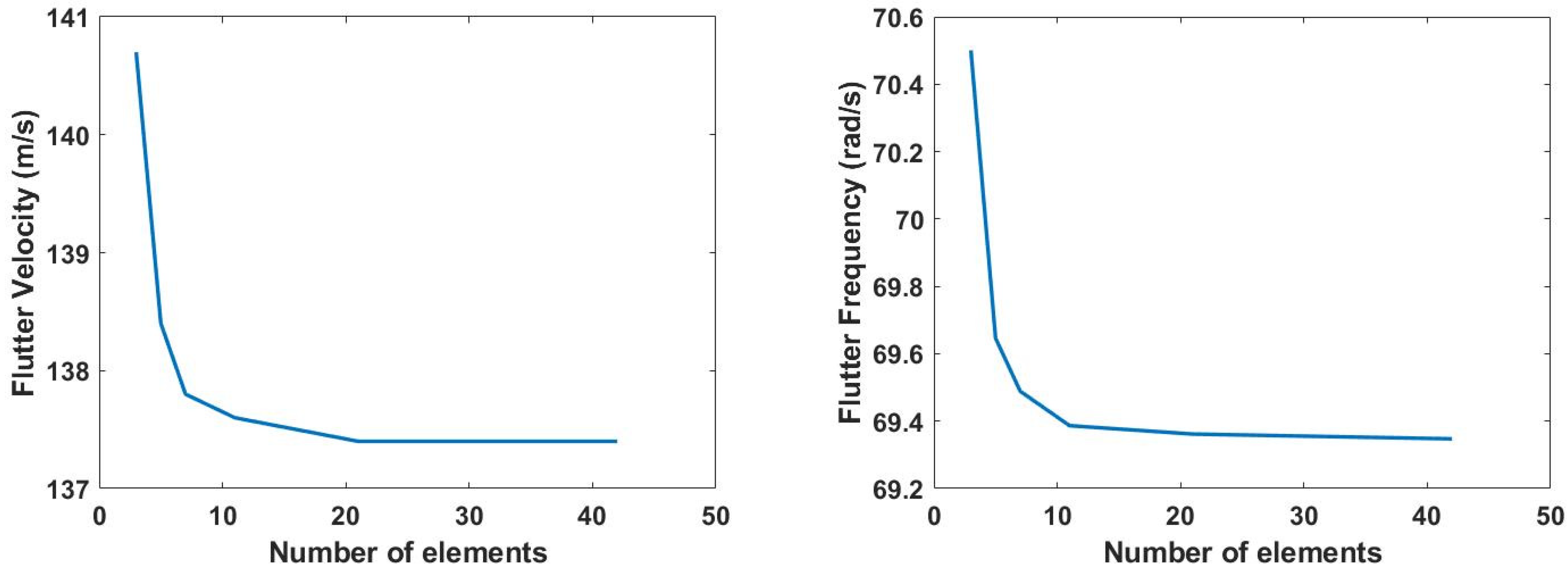
The Goland wing is discretized into three main sections: the inboard section, the outboard section, and the adjoining torsional spring. The inboard and outboard sections are divided into an equal number of elements, whereas the spring is represented by a single element of fixed length (0.1 m). The torsional rigidity of the spring element can be varied by altering the GJ term in Equation (2). A convergence study is performed to determine the optimum number of required elements to achieve a reliable solution. It has been found that the solution converges for a total number of 21 elements, as seen in Figure 6.
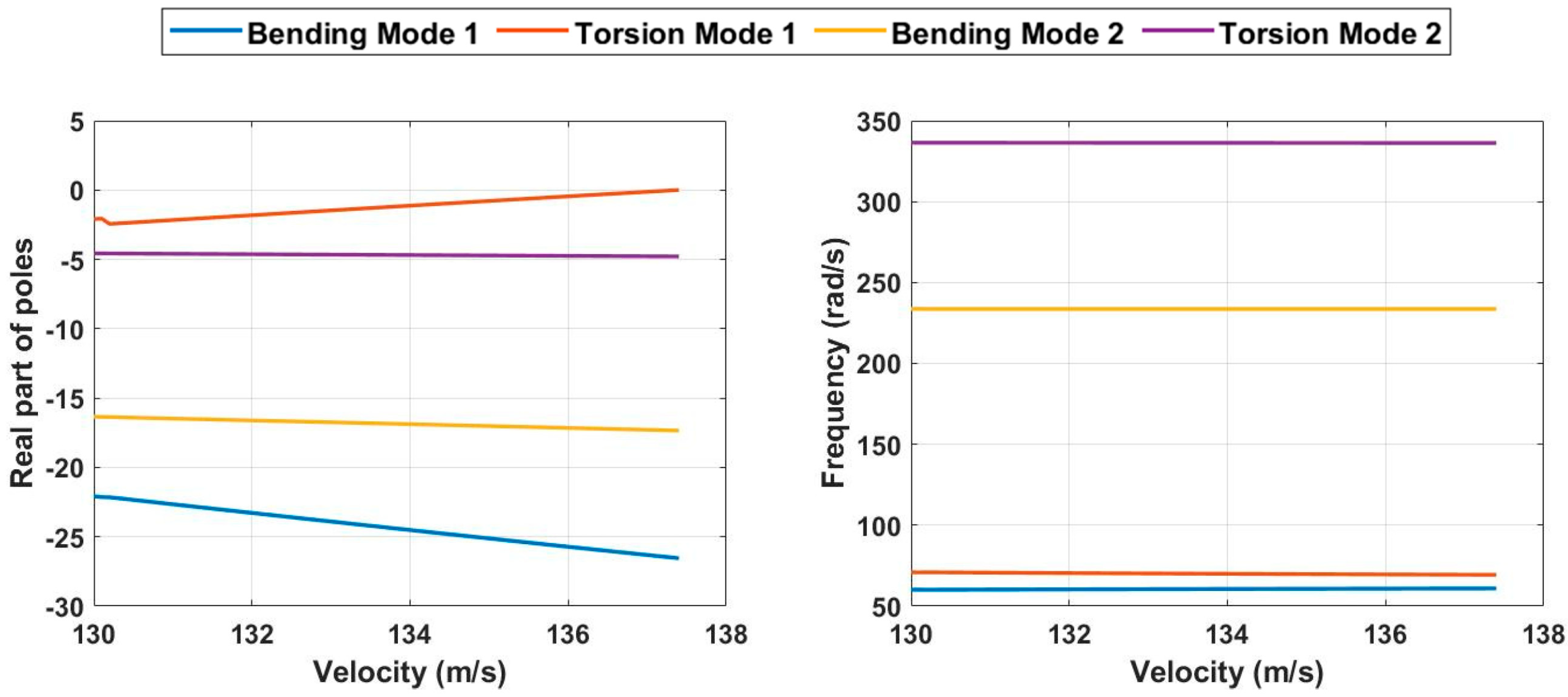
The developed model is validated by determining the aeroelastic boundaries of the Goland wing, and the results for flutter behavior are expressed as the real part of poles and frequency response of the system in Figure 7. The system exhibits instability at the velocity of 137.4 m/s, where the real part of the first torsional model becomes positive, indicating aeroelastic flutter. The result is compared to various studies present in the literature and is shown in Table 2. Similarly for divergence, the model exhibits a high degree of accuracy in comparison to other results reported in the literature.

3. Parametric Analysis

A parametric analysis is performed on the developed model to evaluate the effect of morphing rate on the aeroelastic behavior of the ASAPP wing, as well as to quantify morphing rate influence on load alleviating capabilities. The ASAPP wing is integrated into a Goland wing configuration; therefore, the baseline wing configuration consists of 33% chordwise elastic axis position and 43% chordwise center of gravity location. Moreover, for the baseline case, the torsional rigidity of the torsional spring would be considered equal to the torsional rigidity of the Goland wing. The role of morphing acceleration is ignored, and it is assumed that span extension/retraction takes place at a constant speed. Although the role of morphing acceleration would not be insignificant in certain cases, it is dependent on the exact morphing method and mechanism used to achieve span extension. This is beyond the scope of this paper, and hence, the ensuing effects are ignored. However, it should be noted that the developed model explicitly contains span-morphing acceleration terms and, hence, can account for its effect in future studies. The study is carried out for the ASAPP wing undergoing span morphing from baseline configuration (100% span) to fully extended (125% span extension) for the extension case and vice versa for retraction. For a fair comparison, each analysis is carried out at identical span lengths, characterized by a particular time fraction of the total morphing time. The length of the ASAPP wing for each analysis at the particular time fractions is given in Table 3.

3.1. Morphing Rate Effect on Flutter Behavior at a Half-Span of 6.11 m

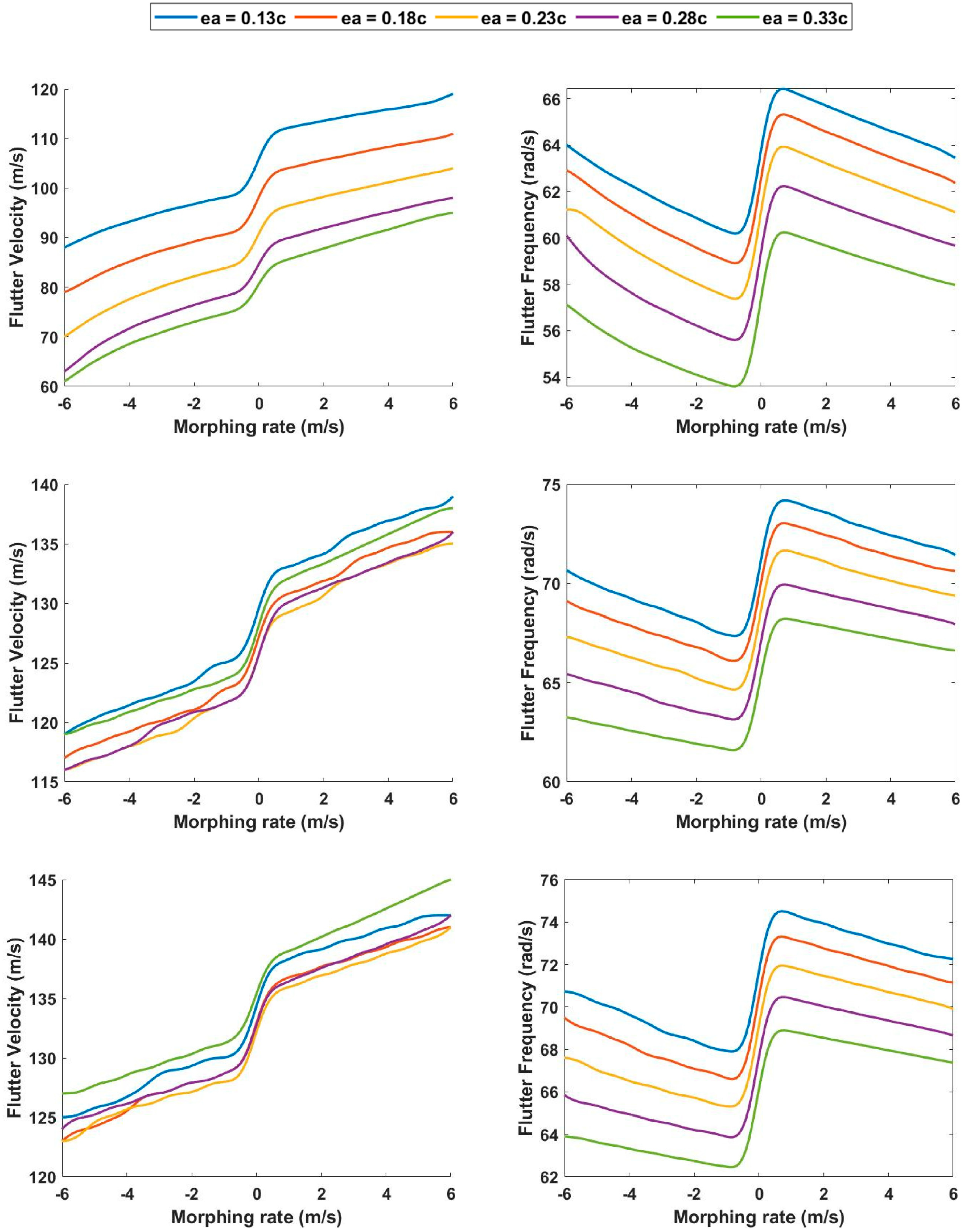
For this analysis, the elastic axis (ea) position of the adjoining torsional spring is varied from 13% to 33% chordwise position, which corresponds to baseline wing configuration, with an increment of 5% for each calculation. Three values of torsional spring rigidity corresponding to 1%, 10%, and 100% torsional rigidity of the baseline wing are selected for the analysis, and the results are plotted in Figure 8. The analysis is carried out at the 1% time fraction of the total morphing time, at a span of 6.111 m, to capture the effects of the morphing rate just after initiation for the extension case, and just before the stoppage for the retraction phase. The results exhibit that a positive morphing rate (extension) contributes to a higher flutter velocity, with higher extension rates having a higher flutter point. The opposite can be seen for negative morphing rates (retraction), with flutter velocity decreasing as the retraction rates are increased. Positive morphing rates add to the system’s damping capabilities and therefore lead to a greater aeroelastic dynamic stability, whereas the opposite is true for negative morphing rates or retraction cases. This behavior is in line with results from previous studies concerning morphing rates of span morphing wings [14,17]. A sharp change in gradient for the flutter velocity can be seen for morphing rate cases very near to the static (0 m/s) case. This can be attributed to the presence of the damping matrix (Equation (19)), which is not present for the static case, but manifests as the system starts to morph at a certain rate. For negative morphing rate (retraction), this damping matrix reduces system stability and therefore causes a sudden decline in flutter velocity, and the opposite is true for positive morphing rate (extension). This region where a sharp change in flutter gradient is evident will be referred to as the morphing rate-dependent flutter transition (MRFT) region in this study. Outside the MRFT boundary, the magnitude of the decrease in the gradient of flutter velocity with increasing retraction rates exceeds the increase in flutter velocity rate of change during extension. Moreover, the rate of change in flutter velocity varies, both inside and outside the MRFT boundary, depending on the elastic axis location of the outer wing section. For the minimum elastic axis position (0.13c) case, the jump in velocity is greatest for the lowest GJ (1% of baseline wing) case and gradually progressively decreases with an increase in GJ from 10% to 100% of the baseline value. For the lowest GJ case, the most forward ea position exhibits the greatest flutter velocity, which decreases as the elastic axis (the torsional spring position) is moved backward. For the 10% GJ case, the most fore ea position still exhibits the highest flutter velocity for extension; however, it is very close to the 0.33c ea position case (baseline case) for higher retraction rates. The baseline wing position of the ea (0.33c) exhibits the greatest flutter velocity for both extension and retraction for the 100% GJ case. It is closely followed by the 0.13c ea case, for which the flutter velocity becomes very close to the 28% ea position case for the highest extension rate. The flutter frequency plots show that a decrease in frequency occurs as the system moves from higher retraction rates to the MRFT boundary. A sharp increase in flutter frequency is observed during the MRFT region, following which a gradual decrease in flutter frequency is evident with an increasing morphing rate. For all three cases, the greatest flutter frequency is observed for the most forward ea position, and it decreases as the elastic axis position is moved backward. It should be noted that for all the presented cases, flutter occurs in the first torsional mode of vibration. It can also be seen that the flutter frequency increases with an increase in spring torsional rigidity.

3.2. Morphing Rate Effect on Flutter Behavior at a Half-Span of 6.86 m

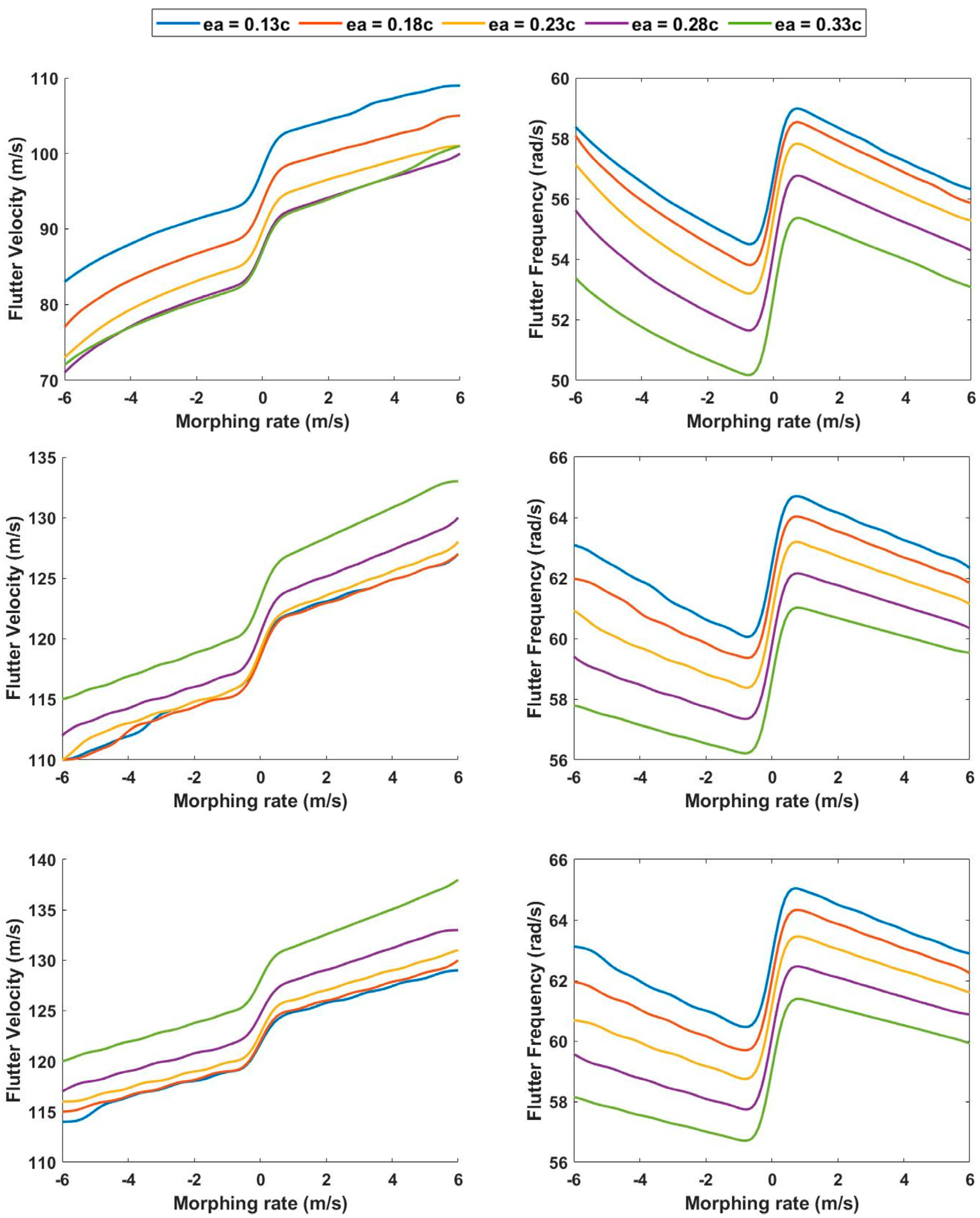
For this analysis, the effect of morphing rate on flutter velocity and flutter frequency is analyzed at the midpoint during the extension/retraction between the baseline span and 125% span configuration. A reduction in overall flutter velocity for all cases in comparison to the previous case of similar GJ is evident in Figure 9. For GJ of 1%, 10%, and 100%, a decrease of 7.6%, 4.5%, and 4.8% is evident for the highest flutter velocity encountered for each of the cases, respectively. It is pertinent to notice that for both the mentioned cases, the greatest flutter velocity occurs for differing ea positions. The overall behavior of the plots is similar to Figure 8; however, for this span for the GJ of 10% and 100%, the most aft position of the elastic axis leads to the greatest flutter velocity, which decreases as the position of ea is moved forward.
During the MRFT zone, the 1% GJ case displays the highest gradient, which lowers as the spring torsional rigidity is increased, and is minimum for the 100% GJ case. The flutter frequency plots exhibit identical behavior to the previous case, being the highest for the most fore position of the elastic axis and decreasing as the ea is moved aft. Overall, the flutter frequencies decrease with the span extension but still increase with greater spring torsional rigidity.

3.3. Morphing Rate Effect on Flutter Behavior at a Half-Span of 7.61 m

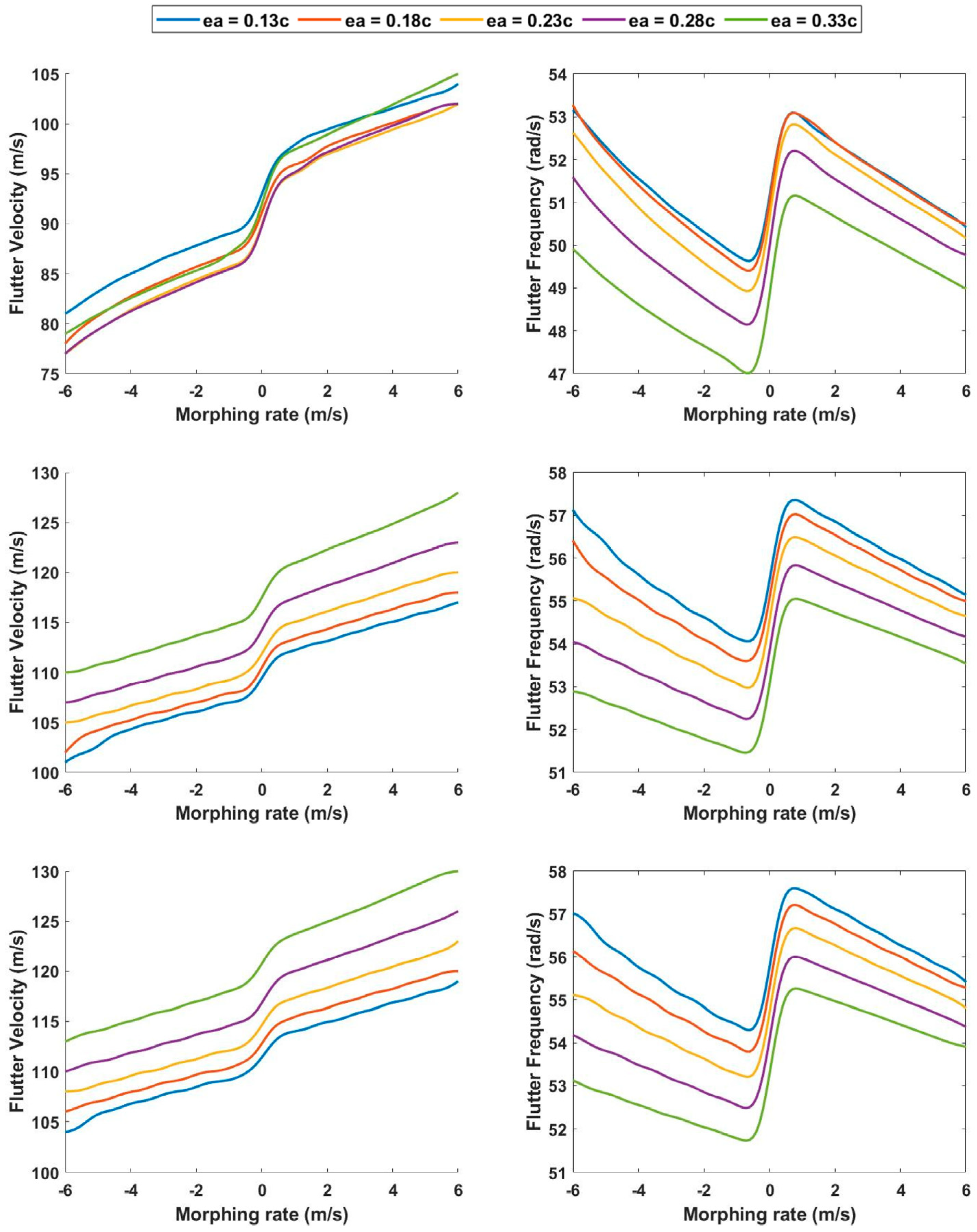
This case was analyzed at a 7.61 m span extension, at the 99th fraction of the total morphing time, to simulate the aeroelastic effects of extraction rate just before the morphing process ends, and also the initiation case for the retraction from 125% span length. For the lowest GJ case, a high overlap of plot lines is evident in Figure 10, with very little difference between the 0.33c and 0.13c ea position at the maximum morphing rate. The other ea positions also exhibit overlapping, becoming identical at times, and converging to a similar value for the highest extension rate calculated. For the minimum GJ position, there exists only a 2.85% difference in the flutter velocity for the maximum and minimum cases. The difference is slightly more pronounced for retraction rates, where the 0.23c and 0.28c cases assume similar values for the highest rate, and 0.33c and 0.28c rates exhibit proximity. For GJ of 1%, 10%, and 100%, a decrease of 11.02 %, 7.91%, and 10.34% is evident for the highest flutter velocity encountered for each of the cases in comparison to 1% of morphing time case, respectively. It is once again important to mention, that these comparisons are drawn for the maximum flutter velocity encountered among all the test cases for a particular GJ value; therefore, the elastic axis position used for the comparison is not necessarily identical. The flutter frequency exhibits similar patterns as per the previous two cases, except a high degree of overlapping is evident for the 0.13c and 0.18c cases at minimum GJ.

4. Conclusions

This paper is concerned with analyzing the effects of morphing rate on the aeroelastic properties of the ASAPP wing, which is a representative polymorphing wing with span and twist-morphing capabilities. A novel variable domain size finite element model is developed based on the Euler–Bernoulli beam formulation, which incorporates the bending and torsional effects. Theodorsen’s unsteady aerodynamic model is used to estimate the aerodynamic loads of the model and strip theory is applied for integration over the half-span. The Lagrangian method is employed for developing the equations of motion and a frequency matching method; the p-k method is used to estimate the aeroelastic flutter boundary of the system. A parametric study is performed which evaluates the effect of morphing rate on flutter velocity and flutter frequency of the ASAPP wing, with change in adjoining spring torsional rigidity and elastic axis location of the passive twisting outboard section.
Morphing rate has considerable effects on the aeroelastic properties of the ASAPP wing. It is shown that for a specific span length, the flutter velocity increases with an increase in extension rate, and decreases with an augmented retraction rate. A morphing rate-dependent flutter transition (MRFT) region is identified, in which the flutter velocity varies more rapidly in comparison to its neighboring quantities, and occurs around the boundary of negative and positive morphing rates. It should be noted that the gradient increase and decrease in flutter outside the MRFT zone are dependent on the span length. An increase in flutter speed of up to 19% is recorded for the highest extension rate, whereas up to 24% decrease in flutter velocity during retraction is recorded in the parametric study. This significant change in aeroelastic stability due to its dependency on span morphing rates highlights the severe need to evaluate these features, especially in cases where high morphing rates are desired, such as asymmetric morphing for roll control one instance. Moreover, this emphasizes that even though an increase in wing stiffness is expected with a decrease in span, the effects of negative structural damping cannot be ignored during the actual morphing process of retraction from a higher to a lower wing span. Overall, the results of this study stress the need to incorporate the effects of the mentioned parameters in the initial design features of any morphing aircraft to reap the complete benefits of the associated morphing technology.

Author Contributions

Conceptualization, Z.H. and R.M.A.; methodology, Z.H. and R.M.A.; validation, Z.H. and R.M.A.; formal analysis, Z.H.; investigation, Z.H. and R.M.A.; resources, R.M.A.; data curation, Z.H.; writing—original draft preparation, Z.H.; writing—review and editing, Z.H., R.M.A. and L.S.; supervision, R.M.A. and L.S.; project administration, Z.H. and R.M.A.; funding acquisition, R.M.A. All authors have read and agreed to the published version of the manuscript.

Funding

The work presented herein has been funded by Abu Dhabi Education Council Award for Research Excellence Program (AARE 2019) through grant number AARE19-213.

Institutional Review Board Statement

Not applicable.

Informed Consent Statement

Not applicable.

Data Availability Statement

The data presented in this study are available on request from the corresponding author.

Conflicts of Interest

The authors declare no conflict of interest.

Nomenclature

B ^ Aerodynamic damping matrix
B ¯ Aerodynamic damping matrix
C ^ Aerodynamic stiffness matrix
C ¯ Structural damping matrix
D ¯ Aerodynamic stiffness matrix
K ¯ Structural stiffness matrix
  L ˙ Rate of change in beam length
M ¯ Structural inertia matrix
m Mass per unit length
CDamping Matrix
C(k)Theodorsen’s transfer function
cgCenter of gravity
EDistance between cg and ea
eaElastic axis location
EIBending Rigidity
GJTorsional Rigidity
KStiffness Matrix
L(t)Instantaneous length of beam
LBTotal length of beam
MMass Matrix
NbHermite’s cubic shape functions
NeCombined bending-torsion shape functions
NtTorsional shape functions
qGeneralized coordinate
rαRadius of gyration
tTime
TKinetic Energy
UPotential Energy
xSpanwise position in ECS
XSpanwise position in GCS
yBending deflection in ECS
YBending deflection in GCS
ȲCombined bending-torsion displacement vector
θ Bending slope in EXS
ϑ Bending slope in GCS
ρDensity
𝓛Lagrangian

References

  1. Ajaj, R.M.; Parancheerivilakkathil, M.S.; Amoozgar, M.; Friswell, M.I.; Cantwell, W.J. Recent developments in the aeroelasticity of morphing aircraft. Prog. Aerosp. Sci. 2021, 120, 100682. [Google Scholar] [CrossRef]
  2. Abdulrahim, M.; Lind, R. Using Avian Morphology to Enhance Aircraft Maneuverability. In Proceedings of the AIAA Atmospheric Flight Mechanics Conference and Exhibit, Keystone, CO, USA, 21–24 August 2006; pp. 1328–1344. [Google Scholar] [CrossRef]
  3. Weisshaar, T. Morphing aircraft technology-new shapes for aircraft design. Multifunct. Struct. Integr. Sens. Antennas 2006, O1-1–O1-20. Available online: http://oai.dtic.mil/oai/oai?verb=getRecord&metadataPrefix=html&identifier=ADA479821 (accessed on 12 November 2022).
  4. Schmitt, D. On the Way to ACARE 2020 and Beyond. In Variational Analysis and Aerospace Engineering: Mathematical Challenges for Aerospace Design; Springer: Boston, MA, USA, 2012; pp. 379–394. [Google Scholar]
  5. Directorate-General for Mobility and Transport and Directorate-General for Research and Innovation. In Flightpath 2050—Publications Office of the EU; EU Publications: Luxembourg, Luxembourg, 2011; pp. 1–32. Available online: https://op.europa.eu/en/publication-detail/-/publication/296a9bd7-fef9-4ae8-82c4-a21ff48be673 (accessed on 2 October 2022).
  6. Ajaj, R.; Flores, E.S.; Amoozgar, M.; Cooper, J. A Parametric Study on the Aeroelasticity of Flared Hinge Folding Wingtips. Aerospace 2021, 8, 221. [Google Scholar] [CrossRef]
  7. Cooper, J.E.; Chekkal, I.; Cheung, R.C.M.; Wales, C.; Allen, N.J.; Lawson, S.; Peace, A.J.; Cook, R.; Standen, P.; Hancock, S.D.; et al. Design of a Morphing Wingtip. J. Aircr. 2015, 52, 1394–1403. [Google Scholar] [CrossRef] [Green Version]
  8. Guo, S.; Li, D.; Sensburg, O. Optimal design of a passive gust alleviation device for a flying wing aircraft. In Proceedings of the 12th AIAA Aviation Technology, Integration, and Operations (ATIO) Conference and 14th AIAA/ISSMO Multidisciplinary Analysis and Optimization Conference, Indianapolis, IN, USA, 17–19 September 2012; pp. 1–12. [Google Scholar] [CrossRef]
  9. Parancheerivilakkathil, M.S.; Haider, Z.; Ajaj, R.M.; Amoozgar, M. A Polymorphing Wing Capable of Span Extension and Variable Pitch. Aerospace 2022, 9, 205. [Google Scholar] [CrossRef]
  10. Ajaj, R.M.; Parancheerivilakkathil, M.S.; Amoozgar, M. ASAPP: A polymorphing wing capable of active span extension and passive pitch. In Proceedings of the AIAA Scitech 2021 Forum, Virtual, 11–15 & 19–21 January 2021; pp. 1–19. [Google Scholar]
  11. Gamboa, P.V.; Santos, P.D.R.; Silva, J.M.A.; Santos, P.M.B. Flutter Analysis of a Composite Variable-span Wing. In Proceedings of the 4th International Conference on Integrity, Reliability and Failure, Funchal, Portugal, 23–27 June 2013; Volume 1, pp. 1–14. [Google Scholar]
  12. Kidane, B.; Troiani, E. Static Aeroelastic Beam Model Development for Folding Winglet Design. Aerospace 2020, 7, 106. [Google Scholar] [CrossRef]
  13. Ajaj, R.M.; I Friswell, M. Aeroelasticity of compliant span morphing wings. Smart Mater. Struct. 2018, 27, 105052. [Google Scholar] [CrossRef] [Green Version]
  14. Andersen, G.; Cowan, D.; Piatak, D. Aeroelastic Modeling, Analysis and Testing of a Morphing Wing Structure. In Proceedings of the 48th AIAA/ASME/ASCE/AHS/ASC Structures, Structural Dynamics, and Materials Conference, Honolulu, HI, USA, 23–26 April 2007; Volume 1. [Google Scholar] [CrossRef]
  15. Zhang, J.; Shaw, A.D.; Wang, C.; Gu, H.; Amoozgar, M.; Friswell, M.I.; Woods, B.K. Aeroelastic model and analysis of an active camber morphing wing. Aerosp. Sci. Technol. 2021, 111, 106534. [Google Scholar] [CrossRef]
  16. Haider, Z.; Ajaj, R.M.; Seneviratne, L. On the Aeroelasticity of the Active Span and Passive Pitching Polymorphing Wing: A Parametric Study. Aerospace 2022, 9, 483. [Google Scholar] [CrossRef]
  17. Huang, R.; Qiu, Z. Transient aeroelastic responses and flutter analysis of a variable-span wing during the morphing process. Chin. J. Aeronaut. 2013, 26, 1430–1438. [Google Scholar] [CrossRef] [Green Version]
  18. Stylianou, M.C. Dynamics of a Flexible Extendible Beam. Ph.D.Thesis, University Microfilms Int./UMI, Ann Arbor, MI, USA, 1993. [Google Scholar]
  19. Stylianou, M.; Tabarrok, B. Finite Element Analysis Of An Axially Moving Beam, Part I: Time Integration. J. Sound Vib. 1994, 178, 433–453. [Google Scholar] [CrossRef]
  20. Patil, M.J.; Hodges, D.H.; Cesnik, C.E.S. Nonlinear Aeroelastic Analysis of Complete Aircraft in Subsonic Flow. J. Aircr. 2000, 37, 753–760. [Google Scholar] [CrossRef] [Green Version]
  21. Raghavan, B.; Patil, M.J. Flight Dynamics of High Aspect-Ratio Flying Wings: Effect of Large Trim Deformation. J. Aircr. 2009, 46, 1808–1812. [Google Scholar] [CrossRef]
Figure 1. ASAPP wing before (top) and after (bottom) span extension [9].
Aerospace 10 00057 g001
Figure 2. ASAPP wing internal structure (left) and actuation mechanism (right) [9].
Aerospace 10 00057 g002
Figure 3. Schematic of a typical wing section.
Aerospace 10 00057 g003
Figure 4. Schematic for cantilever beam with time-varying length L(t).
Aerospace 10 00057 g004
Figure 5. An element in the cantilever beam.
Aerospace 10 00057 g005
Figure 6. Convergence study performed for the finite element model with 1 element for adjoining torsional spring and an equal number of elements for inboard and outboard wing sections.
Aerospace 10 00057 g006
Figure 7. Goland wing flutter modes. Left: Real part of poles vs. Velocity. Right: Frequency vs. Velocity.
Aerospace 10 00057 g007
Figure 8. Left: Flutter Velocity vs. morphing rate for span of 6.111 m. Right: Left: Flutter Frequency vs. morphing rate for span of 6.11 m. Top: GJ = 1% of baseline wing. Middle: GJ = 10% of baseline wing. Bottom: GJ = 100% of baseline wing.
Aerospace 10 00057 g008
Figure 9. Left: Flutter Velocity vs. morphing rate for span of 6.858 m. Right: Left: Flutter Frequency vs. morphing rate for span of 6.86 m. Top: GJ = 1% of baseline wing. Middle: GJ = 10% of baseline wing. Bottom: GJ = 100% of baseline wing.
Aerospace 10 00057 g009
Figure 10. Left: Flutter Velocity vs. morphing rate for span of 7.605 m. Right: Left: Flutter Frequency vs. morphing rate for span of 7.61 m. Top: GJ = 1% of baseline wing. Middle: GJ = 10% of baseline wing. Bottom: GJ = 100% of baseline wing.
Aerospace 10 00057 g010
Table 1. Properties of Goland wing.
SpecificationsGoland Wing
Half span (m)6.096
Chord (m)1.8288
Mass per unit length (m’) (kg/m)35.71
Air density (ρ) (kg/m3)1.225
Moment of inertia per unit length (kgm) around ea8.64
Center of gravity (from leading edge)43% of chord
Elastic axis location (from leading edge)33% of chord
Flexural rigidity (EI) (Nm2)9.77 × 10⁶
Torsional rigidity (GJ) (Nm2)9.87 × 10⁵
Table 2. Comparison of calculated aeroelastic boundaries of Goland wing.
Method
Present WorkRef. [11]Ref. [6]Ref. [14]Ref. [20]Ref. [21]
Flutter Velocity (m/s)137.4137.4136.99137.11135.60136.22
Flutter Frequency (rad/s)69.36169.35169.9769.9070.2070.06
Divergence Speed (m/s)252.54252.31252.47252.80-250.82
Table 3. Span extension lengths of inboard and outboard wing sections.
ASAPP WingInboard Length (m)Outboard Length (m)Total Length (m)
Without span extension4.2671.82886.456
25% span extension4.6331.82886.462
Span at 1% of total morphing time4.2821.82886.111
Span at 50% of total morphing time5.0291.82886.858
Span at 99% of total morphing time5.7761.82887.604
Disclaimer/Publisher’s Note: The statements, opinions and data contained in all publications are solely those of the individual author(s) and contributor(s) and not of MDPI and/or the editor(s). MDPI and/or the editor(s) disclaim responsibility for any injury to people or property resulting from any ideas, methods, instructions or products referred to in the content.