Data Gathering from a Multimodal Dense Underwater Acoustic Sensor Network Deployed in Shallow Fresh Water Scenarios

 ,
,  ,
,
Abstract
:
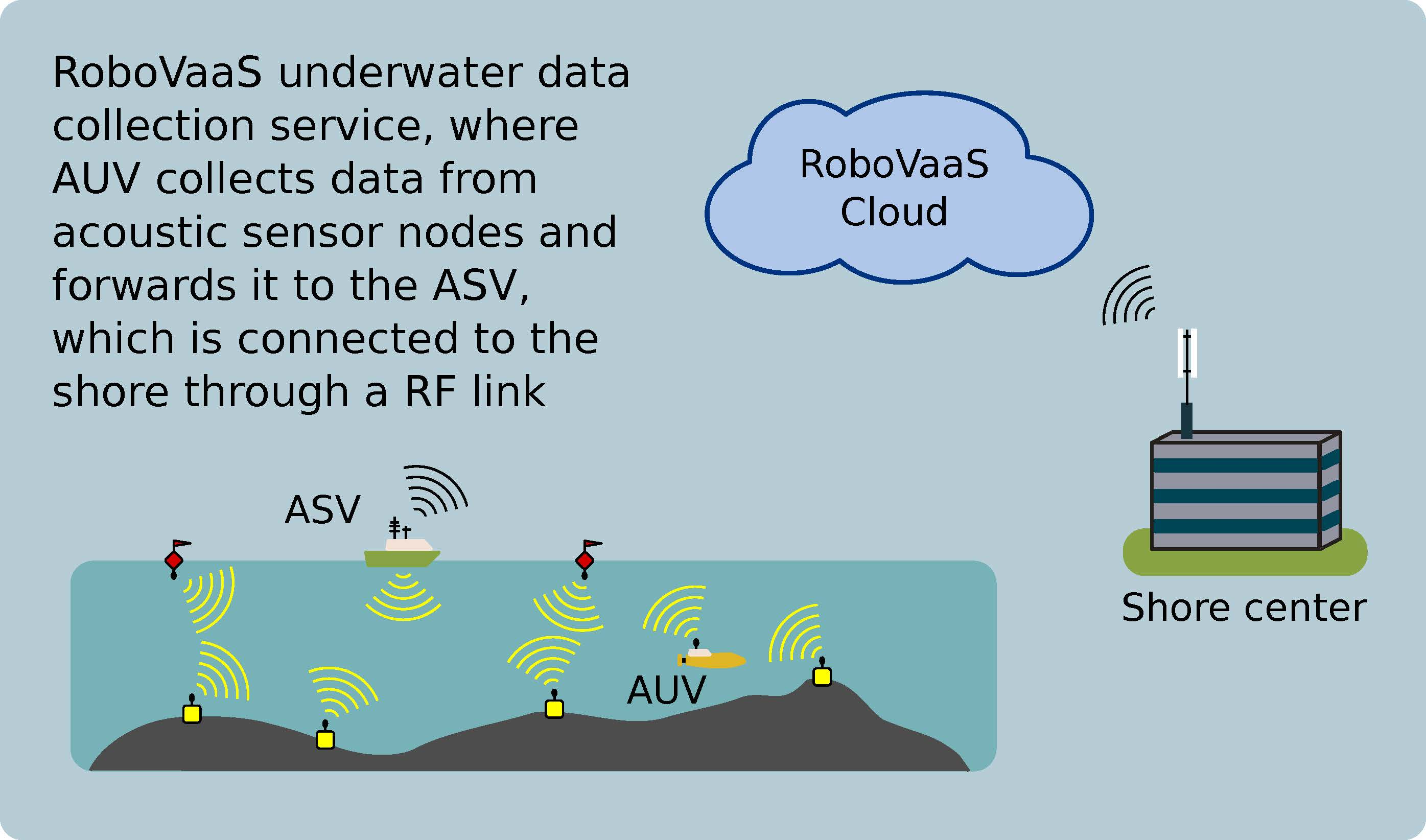
1. Introduction
2. State of the Art
3. Smartport Acoustic Underwater Modem
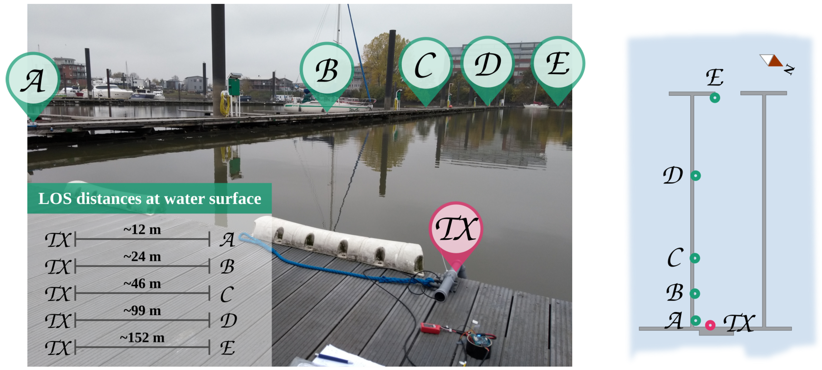
3.1. AHOI Modem Performance in Very Shallow Water
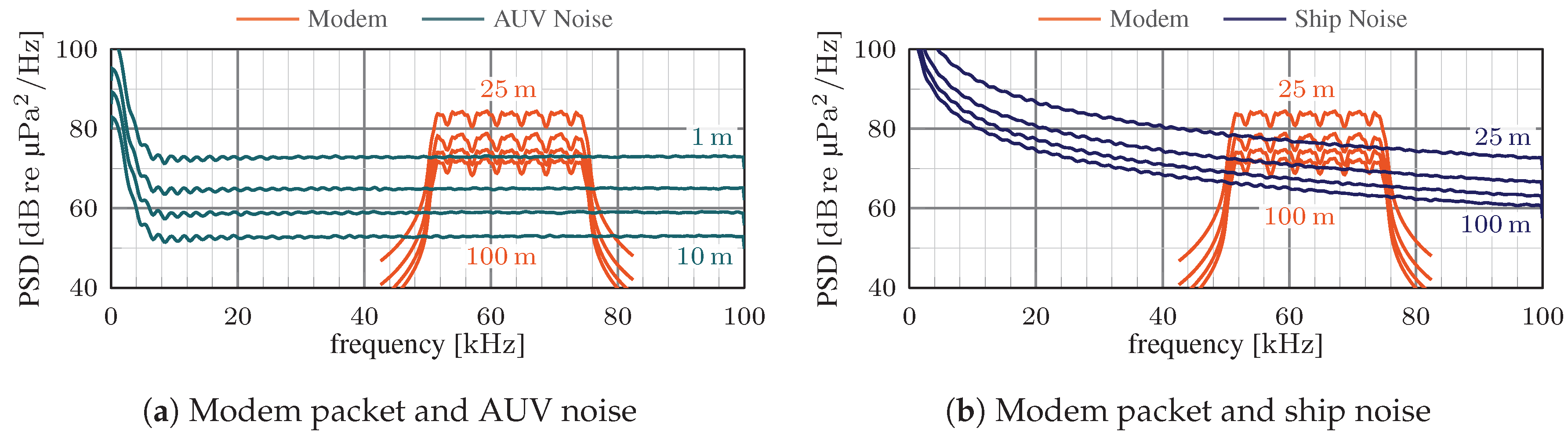
3.2. AHOI Modem’s Reaction to Shipping Noise
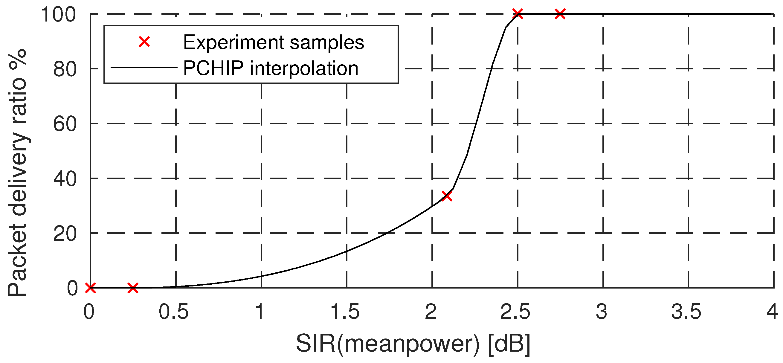
3.3. Modem’s Reaction to Interference
3.4. AHOI Performance Inclusion in the DESERT Underwater Network
4. Protocols Description
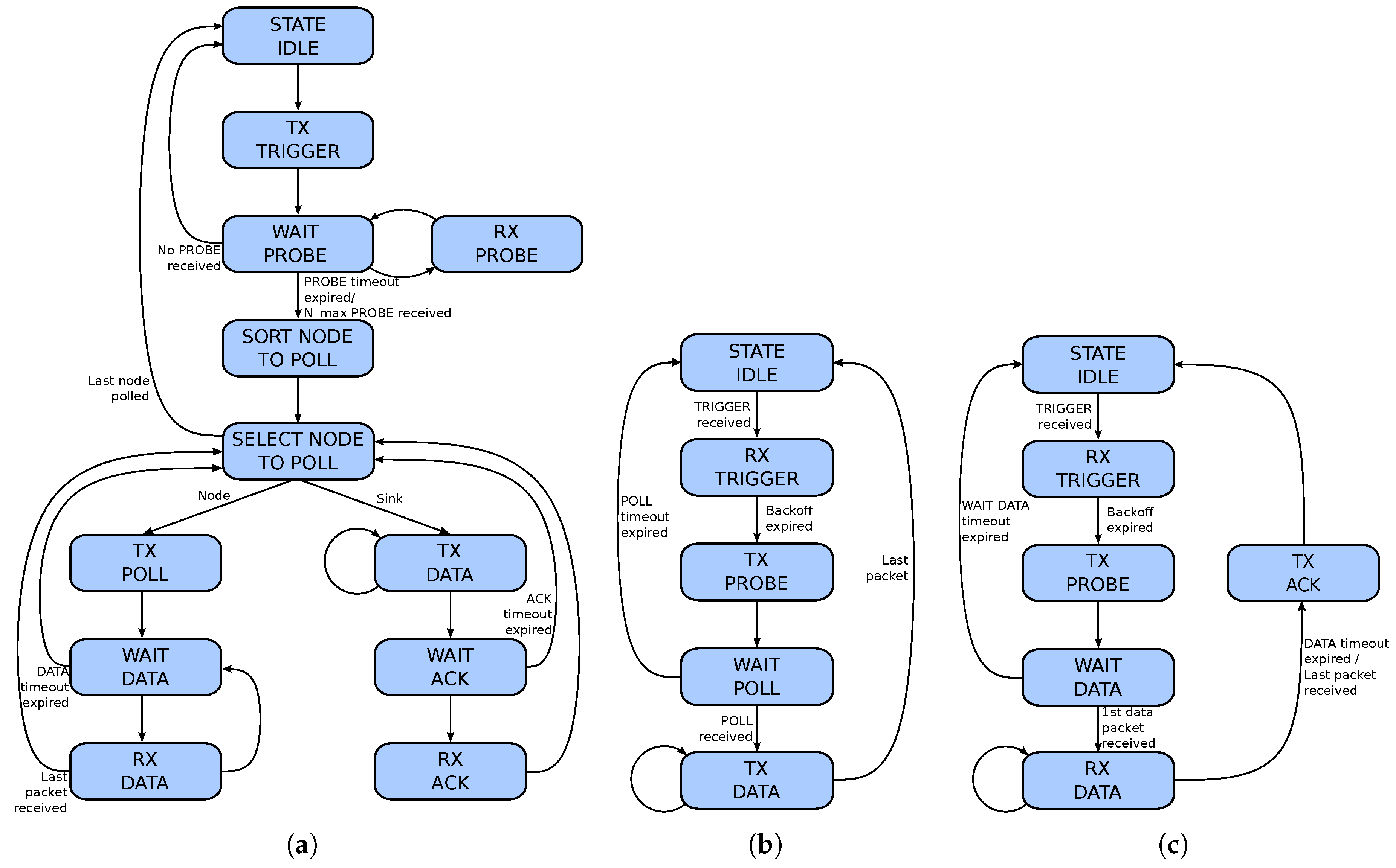
4.1. A Polling-Based Mac Protocol for Underwater Acoustic Networks
4.1.1. Timeout Setting
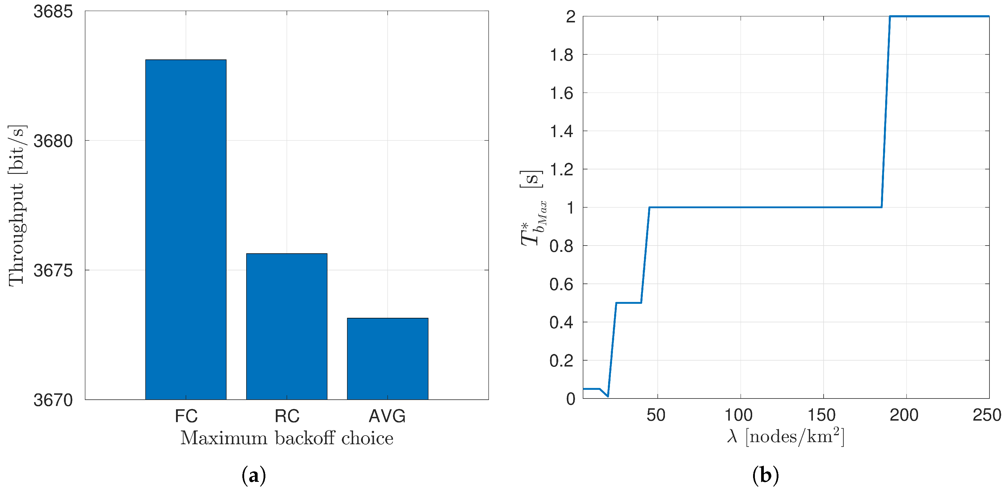
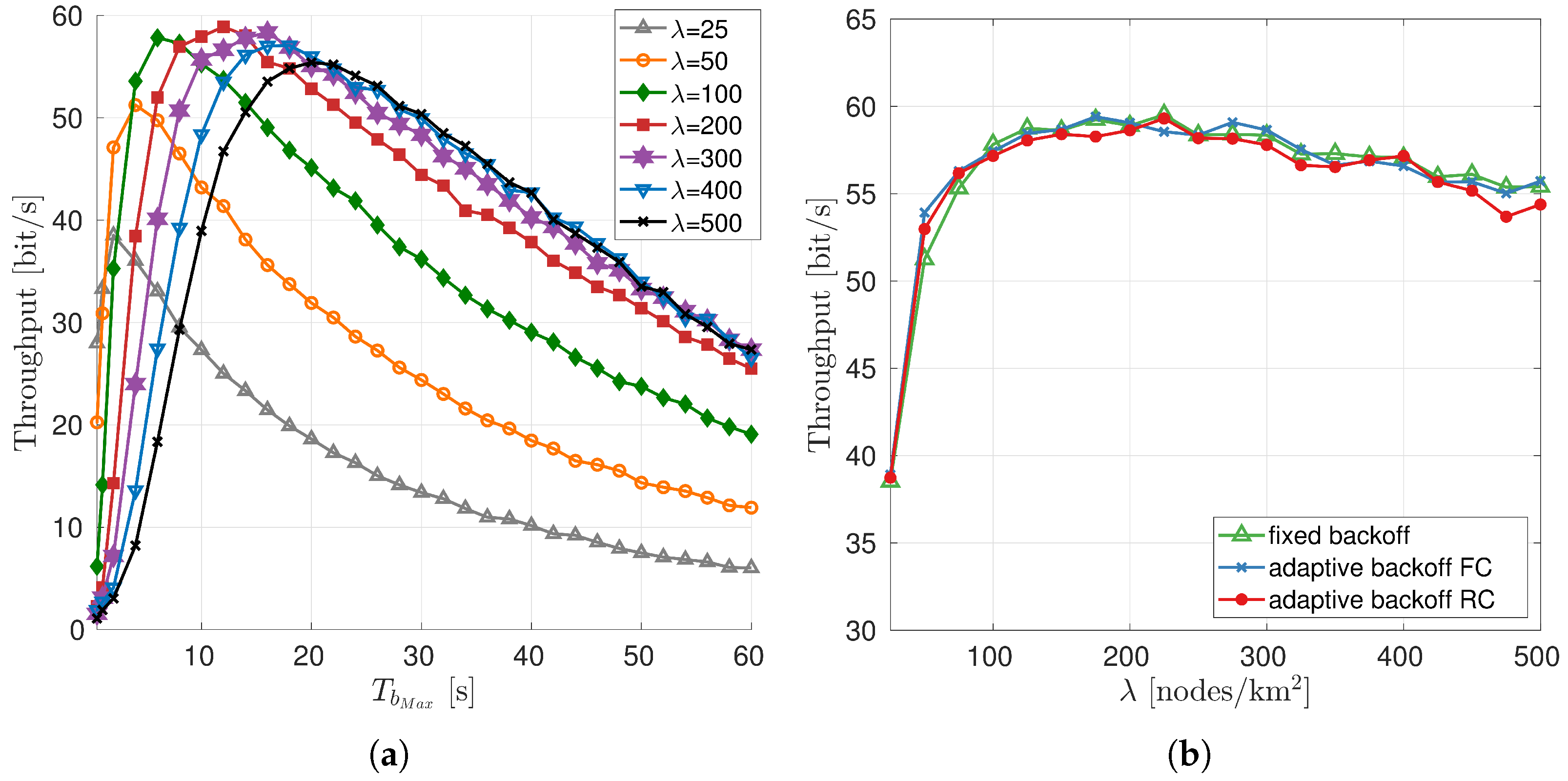
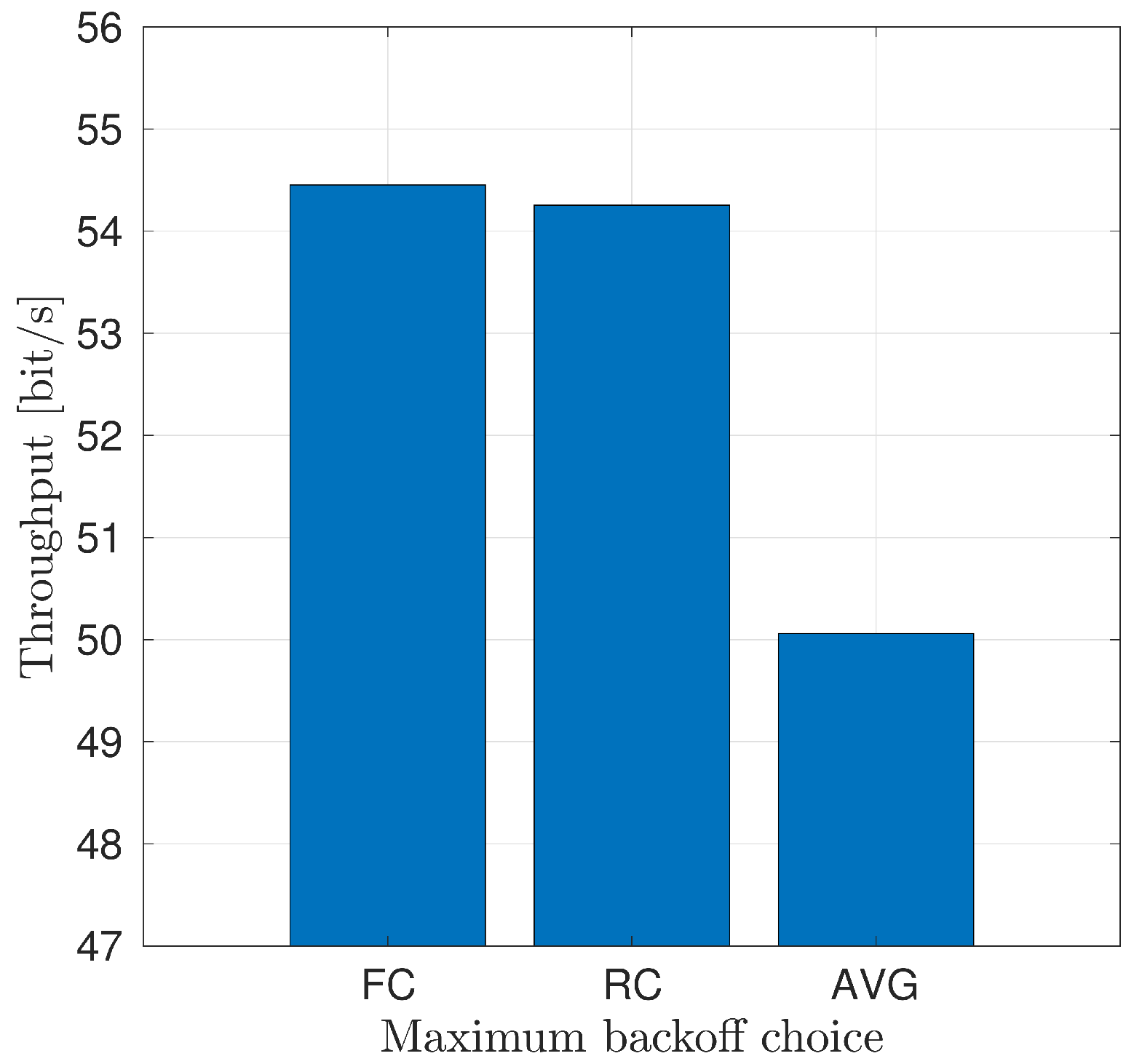
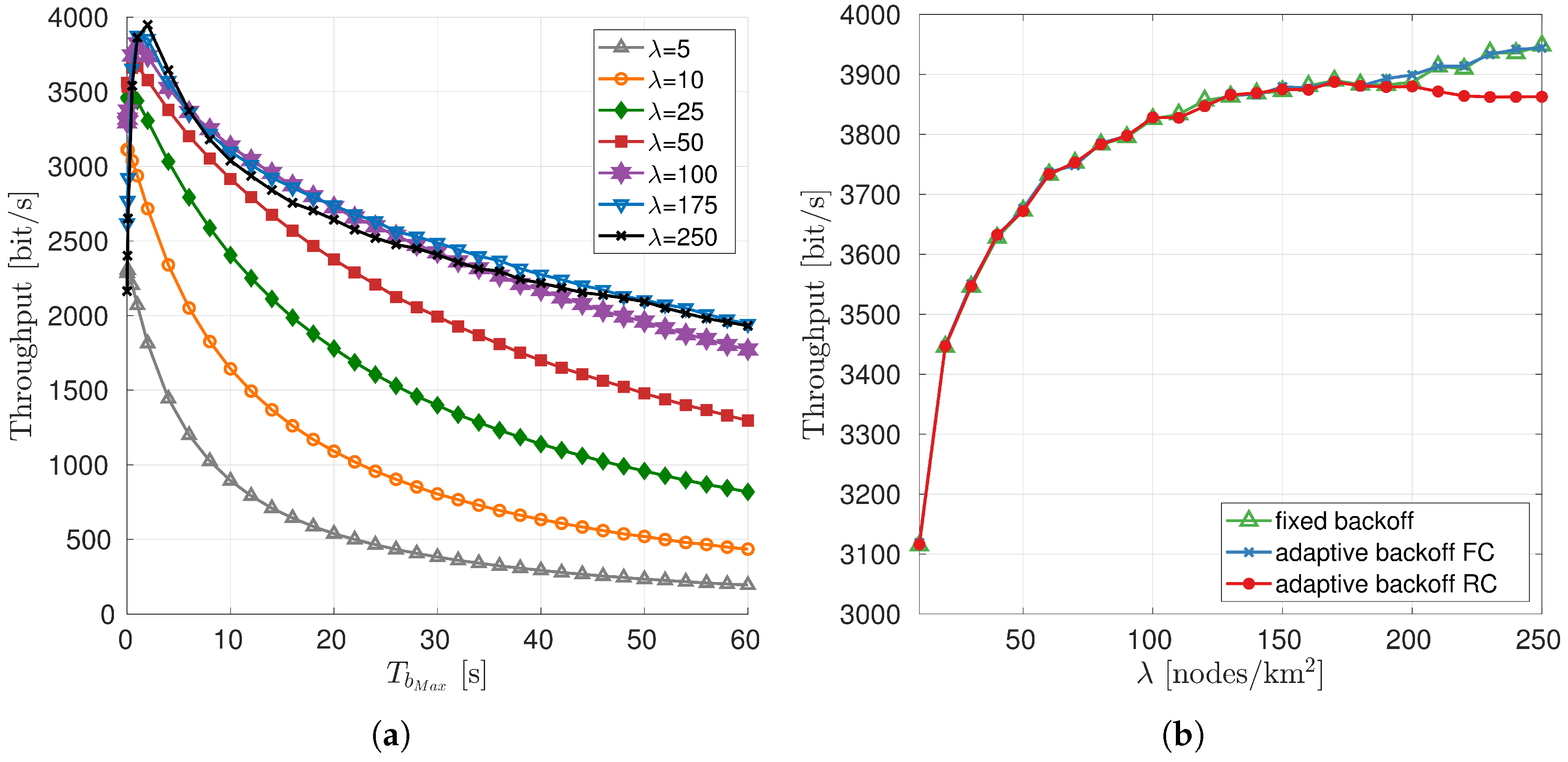
4.1.2. Choice of the Maximum Backoff Time
- assumes full knowledge of the number of s that have been correctly received in the k-th discovery phase and the number of packets discarded () by the physical layer at any time during the simulation. While the former is a parameter well known by the MAC layer, the latter can rarely be determined with high accuracy by a real modem: for this reason the algorithm is used as an upper-bound benchmark. With , the estimated number of neighbors during the k-th discovery phase is calculated aswhere is the total number of lost packets at the beginning of the k-th discovery phase and the total number of lost packets at the end of the same discovery phase.
- assumes knowledge of and , that is, the number of probe packets that have been correctly received and discarded by the MAC layer in the k-th discovery phase, respectively. In this case, both parameters are known by the MAC layer of realistic modems, therefore we are not introducing any assumptions that may favor our solution (this is particularly true for both the AHOI and the EvoLogics modems, although the latter has to be employed with the extended notification activated). The estimated number of neighbors during the k-th discovery phase is calculated as
5. Protocol Evaluation in the Case of a High Speed Acoustic Modem
5.1. Simulation Scenarios and System Settings
5.2. Results
6. Protocol Evaluation in the Case of a Low Rate Acoustic Modem
6.1. Simulation Scenarios and System Settings
6.2. Results
7. Protocol Evaluation in a Multimodal Scenario
7.1. Simulation Scenarios and System Settings
7.2. Results
8. Conclusions
Author Contributions
Funding
Acknowledgments
Conflicts of Interest
Abbreviations
| TRIGGER packet, sent by the AUV to the nodes | |
| PROBE packet, sent by the nodes to the AUV | |
| POLL packet, sent by the AUV to the nodes | |
| Minimum backoff time a node waits before transmitting a | |
| Maximum backoff time a node waits before transmitting a | |
| Number of data packets node i is going to transmit | |
| Maximum number of packets a node can transmit in a polling phase | |
| Maximum number of PrP AUV can receive in a discovery phase | |
| Total number of packets received by AUV from node i | |
| Maximum number of packets AUV can transmit to sink in a polling phase | |
| Node density, that is, the average number of nodes deployed in 1 km2 |
References
- Heidemann, J.; Stojanovic, M.; Zorzi, M. Underwater sensor networks: Applications, advances and challenges. Philos. Trans. R. Soc. A 2012, 370, 158–175. [Google Scholar] [CrossRef] [PubMed]
- Folaga Data Sheet. Available online: https://www.graaltech.com/folaga-features (accessed on 30 November 2019).
- Campagnaro, F.; Francescon, R.; Casari, P.; Diamant, R.; Zorzi, M. Multimodal Underwater Networks: Recent Advances and a Look Ahead. In Proceedings of the International Conference on Underwater Networks & Systems (WUWNET’17), Halifax, NS, Canada, 6–8 November 2017. [Google Scholar]
- Signori, A.; Campagnaro, F.; Zorzi, M. Modeling the Performance of Optical Modems in the DESERT Underwater Network Simulator. In Proceedings of the Fourth Underwater Communications and Networking Conference (UComms), Lerici, Italy, 28–30 August 2018. [Google Scholar]
- Chitre, M.; Shahabudeen, S.; Stojanovic, M. Underwater Acoustic Communications and Networking: Recent Advances and Future Challenges. Mar. Tech. Soc. J. 2008, 42, 103–116. [Google Scholar] [CrossRef]
- Stojanovic, M. On the Relationship Between Capacity and Distance in an Underwater Acoustic Communication Channel. SIGMOBILE Mob. Comput. Commun. Rev. 2007, 11, 34–43. [Google Scholar] [CrossRef]
- Renner, C.; Golkowski, A.J. Acoustic Modem for Micro AUVs: Design and Practical Evaluation. In Proceedings of the 11th ACM International Conference on Underwater Networks & Systems, Shanghai, China, 24–26 October 2016. [Google Scholar]
- Develogic Subsea Systems. Available online: http://www.develogic.de/ (accessed on 30 November 2019).
- S2CR 18/34 Acoustic Modem. Available online: http://www.evologics.de/en/products/acoustics/s2cr_18_34.html/ (accessed on 30 November 2019).
- Teledyne-Benthos Acoustic Modems. Available online: https://teledynebenthos.com/product_dashboard/acoustic_modems (accessed on 30 November 2019).
- Coccolo, E.; Campagnaro, F.; Signori, A.; Favaro, F.; Zorzi, M. Implementation of AUV and Ship Noise for Link Quality Evaluation in the DESERT Underwater Framework. In Proceedings of the Thirteenth ACM International Conference on Underwater Networks & Systems, Shenzhen, China, 3–5 December 2018. [Google Scholar]
- Akyildiz, I.F.; Pompili, D.; Melodia, T. Underwater Acoustic Sensor Networks: Research Challenges. Ad Hoc Netw. 2005, 3, 257–279. [Google Scholar] [CrossRef]
- Signori, A.; Campagnaro, F.; Zordan, D.; Favaro, F.; Zorzi, M. Underwater Acoustic Sensors Data Collection in the Robotic Vessels as-a-Service Project. In Proceedings of the MTS/IEEE OCEANS, Marseille, France, 17–20 June 2019. [Google Scholar]
- Campagnaro, F.; Steinmetz, F.; Signori, A.; Zordan, D.; Renner, B.C.; Zorzi, M. Data Collection in Shallow Fresh Water Scenarios with Low-Cost Underwater Acoustic Modems. In Proceedings of the International Conference and Exhibition on Underwater Acoustics, UACE2019, Crete, Greece, 30 June–5 July 2019. [Google Scholar]
- EvoLogics S2C M HS Modem. Available online: http://www.evologics.de/en/products/acoustics/s2cm_hs.html (accessed on 30 November 2019).
- Campagnaro, F.; Francescon, R.; Guerra, F.; Favaro, F.; Casari, P.; Diamant, R.; Zorzi, M. The DESERT Underwater Framework v2: Improved Capabilities and Extension Tools. In Proceedings of the Third Underwater Communications and Networking Conference (UComms), Lerici, Italy, 30 August–1 September 2016. [Google Scholar]
- Diamant, R.; Casari, P.; Campagnaro, F.; Zorzi, M. Leveraging the Near–Far Effect for Improved Spatial-Reuse Scheduling in Underwater Acoustic Networks. IEEE Trans. Wirel. Commun. 2017, 16, 1480–1493. [Google Scholar] [CrossRef]
- Campagnaro, F.; Guerra, F.; Diamant, R.; Casari, P.; Zorzi, M. Implementation of a Multi-Modal Acoustic-Optic Underwater Network Protocol Stack. In Proceedings of the OCEANS, Shanghai, China, 10–13 April 2016. [Google Scholar]
- Favaro, F.; Casari, P.; Guerra, F.; Zorzi, M. Data Upload from a Static Underwater Network to an AUV: Polling or Random Access? In Proceedings of the OCEANS, Yeosu, Korea, 21–24 May 2012. [Google Scholar]
- Peleato, B.; Stojanovic, M. Distance aware collision avoidance protocol for ad hoc underwater acoustic sensor networks. IEEE Commun. Lett. 2007, 11, 1025–1027. [Google Scholar] [CrossRef]
- Liu, W.; Weaver, J.; Weaver, L.; Whelan, T.; Bagrodia, R.; Forero, P.A.; Chavez, J. APOLL: Adaptive Polling for Reconfigurable Underwater Data Collection Systems. In Proceedings of the MTS/IEEE Kobe Techno-Oceans (OTO), Kobe, Japan, 28–31 May 2018. [Google Scholar]
- Nam, H. Data-Gathering Protocol-Based AUV Path-Planning for Long-Duration Cooperation in Underwater Acoustic Sensor Networks. IEEE Sens. J. 2018, 18, 8902–8912. [Google Scholar] [CrossRef]
- Pescosolido, L.; Petrioli, C.; Picari, L. A multi-band Noise-aware MAC protocol for underwater acoustic sensor networks. In Proceedings of the IEEE 9th International Conference on Wireless and Mobile Computing, Networking and Communications (WiMob), Lyon, France, 7–9 October 2013. [Google Scholar]
- Campagnaro, F.; Favaro, F.; Guerra, F.; Calzado, V.S.; Zorzi, M.; Casari, P. Simulation of Multimodal Optical and Acoustic Communications in Underwater Networks. In Proceedings of the OCEANS, Genova, Italy, 18–21 May 2015. [Google Scholar]
- Han, S.; Noh, Y.; Liang, R.; Chen, R.; Cheng, Y.J.; Gerla, M. Evaluation of underwater optical-acoustic hybrid network. IEEE China Commun. 2014, 11, 1518–1547. [Google Scholar]
- Basagni, S.; Blöni, L.; Gjanci, P.; Petrioli, C.; Phillips, C.A.; Turgut, D. Maximizing the value of sensed information in underwater wireless sensor networks via an autonomous underwater vehicle. In Proceedings of the IEEE INFOCOM 2014—IEEE Conference on Computer Communications, Toronto, ON, Canada, 27 April–2 May 2014. [Google Scholar]
- Gjanci, P.; Petrioli, C.; Basagni, S.; Phillips, C.A.; Boloni, L.; Turgut, D. Path Finding for Maximum Value of Information in Multi-Modal Underwater Wireless Sensor Networks. IEEE Trans. Mob. Comput. 2017, 17, 404–418. [Google Scholar] [CrossRef]
- Kaushal, H.; Kaddoum, G. Underwater Optical Wireless Communication. IEEE Access 2016, 4, 1518–1547. [Google Scholar] [CrossRef]
- Anguita, D.; Brizzolara, D.; Parodi, G.; Hu, Q. Optical wireless underwater communication for AUV: Preliminary simulation and experimental results. In Proceedings of the IEEE/OES Oceans, Santander, Spain, 6–9 June 2011. [Google Scholar]
- Subnero. Available online: https://subnero.com/ (accessed on 30 November 2019).
- MATS 3G Multi-Modulation Acoustic Telemetry System. Available online: http://www.sercel.com/products/Pages/mats3g.aspx (accessed on 30 November 2019).
- LinkQuest Underwater Acoustic Modems. Available online: http://www.link-quest.com/html/models1.htm (accessed on 30 November 2019).
- Beaujean, P.P.; Spruance, J.; Carlson, E.A.; Kriel, D. HERMES—A high-speed acoustic modem for real-time transmission of uncompressed image and status transmission in port environment and very shallow water. In Proceedings of the MTS/IEEE OCEANS, Quebec City, QC, Canada, 15–18 September 2008. [Google Scholar]
- Pelekanakis, C.; Stojanovic, M.; Freitag, L. High rate acoustic link for underwater video transmission. In Proceedings of the Oceans 2003. Celebrating the Past... Teaming Toward the Future (IEEE Cat. No.03CH37492), San Diego, CA, USA, 22–26 September 2003. [Google Scholar]
- Demirors, E.; Shankar, B.G.; Santagati, G.E.; Melodia, T. SEANet: A Software-Defined Acoustic Networking Framework for Reconfigurable Underwater Networking. In Proceedings of the 10th International Conference on Underwater Networks & Systems, ACM WUWNet, Arlington, VA, USA, 22–24 October 2015. [Google Scholar]
- Shimura, T.; Kida, Y.; Deguchi, M. High-rate acoustic communication at the data rate of 69 kbps over the range of 3600 m developed for vertical uplink communication. In Proceedings of the MTS/IEEE OCEANS, Marseille, France, 17–20 June 2019. [Google Scholar]
- Underwater Wireless Acoustic Video Communications Channel. Available online: http://www.baltrobotics.com/index.php/products-services-mnu/item/269-underwater-wireless-acoustic-video-communications-channel (accessed on 30 November 2019).
- Sherlock, B.; Neasham, J.A.; Tsimenidis, C.C. Implementation of a spread-spectrum acoustic modem on an android mobile device. In Proceedings of the MTS/IEEE OCEANS, Aberdeen, UK, 19–22 June 2017. [Google Scholar]
- Low Cost Underwater Acoustic Modem for Makers of Underwater Things and OEMs! Available online: https://dspcommgen2.com/news-flash-low-cost-acoustic-modems-and-transducers-available-for-sale-now/ (accessed on 30 November 2019).
- Cario, G.; Casavola, A.; Lupia, M.; Rosace, C. SeaModem: A Low-Cost Underwater Acoustic Modem for Shallow Water Communication. In Proceedings of the OCEANS, Genova, Italy, 18–21 May 2015. [Google Scholar]
- Sanchez, A.; Blanc, S.; Yuste, P.; Perles, A.; Serrano, J.J. An Ultra-Low Power and Flexible Acoustic Modem Design to Develop Energy-Efficient Underwater Sensor Networks. Sensors 2012, 12, 6837–6856. [Google Scholar] [CrossRef] [PubMed]
- Morozs, N.; Mitchell, P.D.; Zakharov, Y.; Mourya, R.; Petillot, Y.R.; Gibney, T.; Dragone, M.; Sherlock, B.; Neasham, J.A.; Tsimenidis, C.C.; et al. Robust TDA-MAC for practical underwater sensor network deployment: Lessons from USMART sea trials. In Proceedings of the Thirteenth ACM International Conference on Underwater Networks & Systems, ACM WUWNet, Shenzhen, China, 3–5 December 2018. [Google Scholar]
- Benson, B.; Li, Y.; Faunce, B.; Domond, K.; Kimball, D.; Schurgers, C.; Kastner, R. Design of a Low-Cost Underwater Acoustic Modem. IEEE Embed. Syst. Lett. 2010, 2, 58–61. [Google Scholar] [CrossRef]
- Aquarian Audio & Scientific. AS-1 Hydrophone. Available online: http://www.aquarianaudio.com/as-1-hydrophone.html (accessed on 30 November 2019).
- Stojanovic, M.; Preisig, J. Underwater acoustic communication channels: Propagation models and statistical characterization. IEEE Commun. Mag. 2009, 47, 84–89. [Google Scholar] [CrossRef]
- Steinmetz, F.; Renner, C. Resilience against Shipping Noise and Interference in Low-Power Acoustic Underwater Communication. In Proceedings of the MTS/IEEE OCEANS, Seattle, WA, USA, October 2019; Available online: http://www.bcrenner.de/publications/2019_OCEANS_ModemNoise.pdf (accessed on 30 November 2019).
- Sea & Sun Technology GmbH. Available online: https://www.sea-sun-tech.com/product/multiparameter-probe-ctd-48/ (accessed on 30 November 2019).
- Rizzo, W.; Signori, A.; Campagnaro, F.; Zorzi, M. AUVs Telemetry Range Extension through a Multimodal Underwater Acoustic Network. In Proceedings of the IEEE/MTS OCEANS, Charleston, SC, USA, 22–25 October 2018. [Google Scholar]
- Diamant, R.; Francescon, R.; Zorzi, M. Topology-Efficient Discovery: A Topology Discovery Algorithm for Underwater Acoustic Networks. IEEE J. Ocean. Eng. 2018, 43, 1200–1214. [Google Scholar] [CrossRef]
- Miao, G.; Zander, J.; Sung, K.W.; Slimane, S.B. Fundamentals of Mobile Data Networks; Cambridge University Press: Cambridge, UK, 2016. [Google Scholar]
- Diamant, R. Robust Interference Cancellation of Chirp and CW Signals for Underwater Acoustics Applications. IEEE Access 2018, 6, 4405–4415. [Google Scholar] [CrossRef]
- The World Ocean Simulation System—WOSS. Available online: http://telecom.dei.unipd.it/ns/woss/ (accessed on 30 November 2019).
- Le Boudec, J.-Y. Performance Evaluation of Computer and Communication Systems; Epfl Press: Boca Raton, FL, USA, 2011. [Google Scholar]


| Payload | PDR (12 m) | PDR (24 m) | PDR (46 m) | PDR (99 m) | PDR (152 m) |
|---|---|---|---|---|---|
| 4 Byte | 93.5% | 83.0% | 84.0% | 95.5% | 91.0% |
| 8 Byte | 96.5% | 90.0% | 94.0% | 99.0% | 60.0% |
| 16 Byte | 96.5% | 75.0% | 89.5% | 88.0% | 84.5% |
| 32 Byte | 95.0% | 70.0% | 88.5% | 99.0% | 51.5% |
| 25 m | 50 m | 75 m | 100 m | |
|---|---|---|---|---|
| 25 m | 100.0% | 100.0% | 100.0% | 99.8% |
| 50 m | 100.0% | 100.0% | 100.0% | 100.0% |
| 75 m | 98.8% | 100.0% | 100.0% | 100.0% |
| 100 m | 36.2% | 100.0% | 100.0% | 100.0% |
© 2019 by the authors. Licensee MDPI, Basel, Switzerland. This article is an open access article distributed under the terms and conditions of the Creative Commons Attribution (CC BY) license (http://creativecommons.org/licenses/by/4.0/).
Share and Cite
Signori, A.; Campagnaro, F.; Steinmetz, F.; Renner, B.-C.; Zorzi, M. Data Gathering from a Multimodal Dense Underwater Acoustic Sensor Network Deployed in Shallow Fresh Water Scenarios. J. Sens. Actuator Netw. 2019, 8, 55. https://doi.org/10.3390/jsan8040055
Signori A, Campagnaro F, Steinmetz F, Renner B-C, Zorzi M. Data Gathering from a Multimodal Dense Underwater Acoustic Sensor Network Deployed in Shallow Fresh Water Scenarios. Journal of Sensor and Actuator Networks. 2019; 8(4):55. https://doi.org/10.3390/jsan8040055
Chicago/Turabian StyleSignori, Alberto, Filippo Campagnaro, Fabian Steinmetz, Bernd-Christian Renner, and Michele Zorzi. 2019. "Data Gathering from a Multimodal Dense Underwater Acoustic Sensor Network Deployed in Shallow Fresh Water Scenarios" Journal of Sensor and Actuator Networks 8, no. 4: 55. https://doi.org/10.3390/jsan8040055
APA StyleSignori, A., Campagnaro, F., Steinmetz, F., Renner, B.-C., & Zorzi, M. (2019). Data Gathering from a Multimodal Dense Underwater Acoustic Sensor Network Deployed in Shallow Fresh Water Scenarios. Journal of Sensor and Actuator Networks, 8(4), 55. https://doi.org/10.3390/jsan8040055