Article

Scalable Edge Computing Deployment for Reliable Service Provisioning in Vehicular Networks

DEI—University of Bologna, Viale del Risorgimento, 2, 40136 Bologna, Italy
*
Author to whom correspondence should be addressed.
J. Sens. Actuator Netw. 2019, 8(4), 51; https://doi.org/10.3390/jsan8040051
Submission received: 2 September 2019 / Revised: 18 September 2019 / Accepted: 29 September 2019 / Published: 2 October 2019
(This article belongs to the Special Issue Advances in Vehicular Networks)

Abstract

:
The global connected cars market is growing rapidly. Novel services will be offered to vehicles, many of them requiring low-latency and high-reliability networking solutions. The Cloud Radio Access Network (C-RAN) paradigm, thanks to the centralization and virtualization of baseband functions, offers numerous advantages in terms of costs and mobile radio performance. C-RAN can be deployed in conjunction with a Multi-access Edge Computing (MEC) infrastructure, bringing services close to vehicles supporting time-critical applications. However, a massive deployment of computational resources at the edge may be costly, especially when reliability requirements demand deployment of redundant resources. In this context, cost optimization based on integer linear programming may result in being too complex when the number of involved nodes is more than a few tens. This paper proposes a scalable approach for C-RAN and MEC computational resource deployment with protection against single-edge node failure. A two-step hybrid model is proposed to alleviate the computational complexity of the integer programming model when edge computing resources are located in physical nodes. Results show the effectiveness of the proposed hybrid strategy in finding optimal or near-optimal solutions with different network sizes and with affordable computational effort.

1. Introduction

Connected vehicles can provide a large set of services for smarter and safer mobility. As an example, a problem highly felt worldwide is road safety [1] where vehicular networks can help in providing prompt information to drivers and alerting possible dangerous situations by allowing vehicles to communicate with each other. It is possible to distinguish between short-range direct communications and long-range network communications [2,3]. Different communications need different network requirements, such as low latency, high computational capacity, and high reliability, depending on the application [4].
To provide the aforementioned services, 5G networks can be used to carry data to/from vehicles and road infrastructure. Centralized cloud-based Radio Access Networks (C-RANs) represent an effective solution to design high-capacity radio access in 4G and 5G networks and to support challenging use cases [5], such as the ones of vehicular networks. C-RAN introduces unprecedented flexibility by efficient application of Network Function Virtualization (NFV) [6] jointly with Software Defined Networking (SDN) [5,7,8]. SDN can, in fact, provide suitable control and management support to optimally locate virtualized network functionalities to intelligent nodes in the cost and power efficiency perspectives. This is of particular importance when considering highly dynamic and performance-constrained contexts as happens in 5G networking. In addition, to ensure timely network adaptation to user needs, SDN control and management must cope with a potentially high number of network elements and, consequently, the design of control algorithms calls for highly scalable approaches. Virtualized baseband functionalities are suitably located and centralized in the nodes of the optical transport network implementing a C-RAN for enhanced functionality and cost-optimization purposes [7]. The nodes hosting these pooled virtual baseband units (BBUs) are called BBU hotels. BBU hotels can be provided with an additional computational capacity to perform time-sensitive operations required by low-latency services, as per the Multi-access Edge Computing (MEC) paradigm [9]. MEC, by providing 5G with processing resources at the network edge, allows to achieve stringent application requirements. However, widespread deployment of these nodes may be costly; therefore, intelligent nodes hosting BBU hotels and edge computing resources need to be identified in relation to latency and processing constraints. Moreover, the problem of BBU hotel placement in C-RAN has been shown to be NP-hard [10], requiring novel strategies to make optimal approaches more scalable.
This paper proposes an Integer Linear Program (ILP) to solve the joint deployment problem of baseband processing and edge computing with reliability against single-node failure in C-RAN. The main objective of this strategy is to minimize the nodes in which processing capabilities must be installed while ensuring latency and optical link (i.e., maximum wavelengths over fibers) constraints are not violated. To overcome the computational complexity of classical optimization approaches, a hybrid (based on both heuristic and ILP) deployment strategy is also proposed. The algorithm performs a first phase in which the initial set of nodes candidate to host baseband and edge computing functions is reduced and a suboptimal solution is provided. Then, a second phase is executed for optimization purposes. The latter approach is shown to provide results close to optimal ones while considerably reducing computational time.
The paper is organized as follows. In Section 2, related works in the context are introduced. Section 3 provides an overview of the reference C-RAN architecture and describes the deployment problem. In Section 4, the optimization problem is formulated, while Section 5 presents the hybrid model. In Section 6, the numerical results obtained in different scenarios are presented. Finally, Section 7 concludes the paper.

2. Background

In Reference [11], the Vehicular Edge Computing (VEC) architecture is analyzed. VEC is composed of three layers: users, MEC, and cloud. In the user layer, vehicles exchange information with each other or with road infrastructure through different protocols, such as the ones reported in References [12,13]. Mobile networks can also be used for vehicular communications to directly send/retrieve data to/from vehicles or road infrastructure [14]. Data are then carried to the MEC or cloud layers, where different services are located. The MEC layer is usually needed to provide low-latency services or to offload the network by means of content caching [14]. The cloud layer, instead, is located deeper in the network and offers extensive computational capacity for heavy data processing and non-time-senstive applications.
The adoption of 5G new radio allows to use its efficient cell coordination and interference management mechanisms as well as novel discovery techniques to improve performance in dense scenarios. With 5G deployments, C-RAN will gradually take over conventional distributed networks in favor of more efficient centralized networks [15]. In C-RAN, antennas and Remote Radio Units (RRUs) are usually located at antenna sites, while BBUs are decoupled from RRUs and placed in central locations [5]. Part or all the baseband processing functions realizing the mobile network protocol stack are performed in the BBUs, where they can be virtualized over general-purpose hardware to decrease network costs [5]. Depending on the specific functions performed in the different units, traffic with different characteristics is transported over the so-called fronthaul links interconnecting them [16]. According to the adopted functional split, the nodes of the transport network can operate at different layers of the protocol stack [17]. Multiple splits can also be defined depending on different levels of baseband function centralization [18,19]. MEC will also play a fundamental role in 5G to meet low-latency service requirements [9,20]. Recently, different architectures have been proposed for edge computing [21]. Edge data centers can be co-located with 4G or 5G baseband processing functions to reduce the delay by bringing services closer to the users [9]. This is of particular relevance for vehicular networks that can take advantage of this to offer Ultra Reliable and Low-Latency Communication services (URLLC) over 5G networks. However, the cost for a large-scale reliable deployment of edge core and cloud resources must be taken into consideration and calls for cost-efficient deployment strategies.
In References [22,23], the authors present optimal and suboptimal strategies for placement of edge resources in 5G networks. In Reference [22], a framework to optimize the placement of primary and backup 5G user plane functions (UPFs) at the edge is provided. The proposed deployment strategies aim at configuring edge resources at a minimum cost while ensuring service demands are met. Results show the amount and use of required UPF for different scenarios and provide a complexity analysis and the execution time of different algorithms. However, the proposed model considers only backhaul links and do not account for the finite optical link capacity, which may affect the solution, especially when dealing with very high bitrate requirements of Fronthaul links. The model in Reference [23], instead, focuses on the number of edge nodes to be equipped with computational capacity, which is shown to increase with the number of base stations deployed in the area.
Deployment strategies for C-RAN have been proposed recently for Wavelenght Division Multiplexing (WDM) networks based on ILP and heuristic strategies [24,25]. Reliability aspects for C-RAN deployment are analyzed in detail in References [10,26,27]. In References [28], the authors propose a fog computing framework for C-RAN in vehicular networks. Simulation results show that low latency can be achieved with edge computing under different traffic conditions. However, no consideration has been made on the deployment of C-RAN processing functions in access/aggregation networks. In Reference [29], the authors propose an edge server placement for MEC in distributed RAN based on integer programming. The proposed approach is compared with different benchmarking strategies. Results show how the different strategies perform in terms of edge service access delay for different numbers of edge nodes using a realistic dataset. While the focus of this work is on distributed RAN, in C-RAN, specific constraints on latency and bandwidth requirements set by the baseband processing at the physical layer are needed. In addition, resiliency aspects are not considered in Reference [29]. The work in Reference [30] proposes an ILP and a heuristic for the deployment of cloud fog RAN. The authors conduct an extensive analysis of the trade-offs among the minimization of propagation latency and power consumption, but no mention of reliability aspects against failures is made. The work in Reference [26] is extended here with proper routing (i.e., not based on precomputed shortest path), and considerations on edge computing deployment for URLLC services in C-RAN are made. A novel heuristic strategy is also proposed to reduce the computational complexity of the optimization problem by properly reducing the set of possible locations for C-RAN and MEC infrastructure.

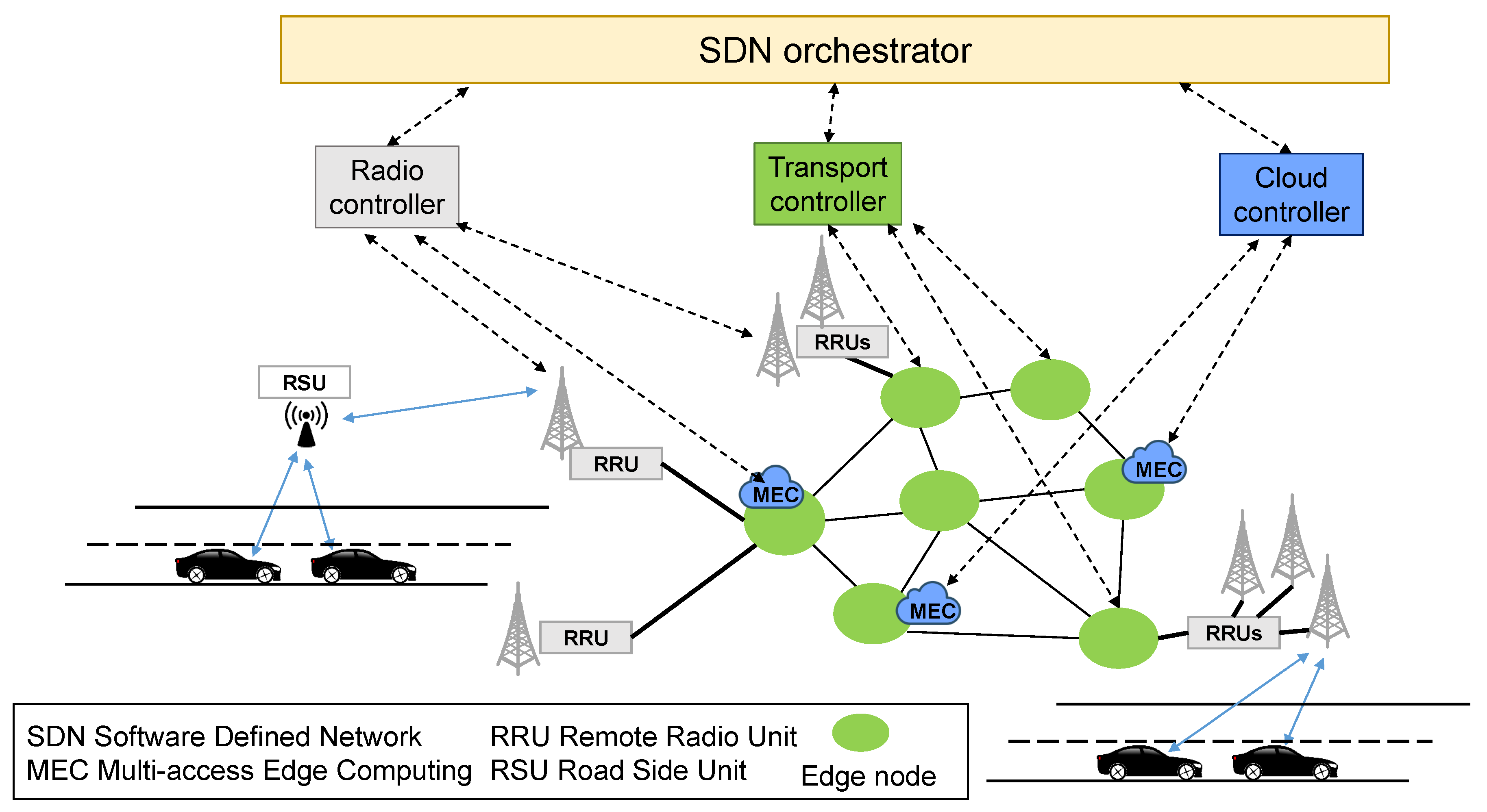
3. Architectural Solution and Problem Formulation

The reference C-RAN architecture has been introduced in previous works [7,31]. It consists of a hierarchical SDN control plane with a lower layer split into as many controllers as the different kinds of network domains to control, namely the radio network, the optical transport network, and the cloud network. An example of this architectural solution applied to vehicular scenarios is shown is Figure 1. The radio domain is composed of antennas and RRUs located at cell sites, and baseband processing functions that are performed over general-purpose hardware in edge nodes. The radio controller is in charge of controlling radio and baseband resources that are remotized following the C-RAN design concept. The optical transport network consists of a set of intelligent nodes interconnected by Dense Wavelength Division Multiplexing (DWDM) optical links to support high-capacity fronthaul in C-RAN. For example, to support heavy and constant fronthaul traffic generated by the Common Public Radio Interface (CPRI) split [19] (referred to as Option 8 in Reference [18]), dedicated wavelengths are usually required. Nodes of the transport network, referred to here as edge nodes, are equipped with processing capabilities to perform MEC functionalities and are managed by the cloud controller. Each controller interacts with the SDN orchestrator to provide information for interworking control and management functions through different domains. The orchestrator is in charge of accommodating new service requests by suitably allocating required resources across the different domains. The orchestrator applies suitable algorithms to properly select the nodes in which the BBU functionalities and services are executed, depending on service and physical network constraints.
C-RAN architecture can be used as an enabler for vehicular communications providing network assistance and commercial services, as depicted in Figure 1. Vehicles communicate directly with the mobile network or with Road Side Units (RSUs), that send collected data through the mobile network. Data concerning low-latency applications can be elaborated directly in the edge nodes, thanks to the computational resources offered by the MEC. Computational resources in edge nodes can be used for (i) virtual baseband processing; (ii) virtual mobile core network functions; and (iii) edge application services [32]. Non-time-sensitive data can be delivered to applications performed in remote locations (not reported in the figure). The traffic destined to remote cloud resources is user dependent and requires lower bandwidth with respect to fronthaul requirements [16] and is out of the scope of this paper. In this work, we propose to co-locate, within the same edge node, cloud and BBU processing functions. An edge node is considered to be active when it hosts physical or virtual functions, either for BBU processing or edge core/cloud services.
To provide a reliable C-RAN against single node failures, a 1 + 1 protection solution is desirable to avoid temporary service outages due to resource restoration. Primary and backup path resources must be allocated to provide resiliency against hardware failures. This work considers single active edge node failures (i.e., a failure of all servers placed in an active edge node). The formulation of the joint BBU hotel and edge cloud processing location problem with resiliency is as follows:
  • Given a set of RRUs to be connected to active edge nodes, a set of edge nodes (candidates to host BBU and edge processing resources), and a set of links connecting edge nodes.
  • Find active edge nodes and suitable optical resource assignment such that (i) the number of active nodes and (ii) total wavelengths are minimized.
  • Ensure that each RRU is connected to two active edge nodes (one for primary and one for backup purposes) and that the maximum available wavelengths per link and maximum allowed distance to provide target service are not exceeded.

4. ILP-Based Optimization

This section proposes an ILP formulation of the problem. This algorithm is expected to be executed by the orchestrator, which is assumed to have complete knowledge of the underlying network topology and available resources to provide the placement. The notation used in the algorithm is reported in Table 1. The set of nodes in the network, the candidate to host BBU and edge processing functions, is denoted as N, while the number of sources (RRUs) physically connected to node s N is denoted as R s . The connectivity among them is modeled by the C binary matrix. C has one row and one column for each node, and an element is equal to 1 if the two nodes are directly connected by a link, 0 otherwise. Binary variables p s d H and b s d H are equal to 1 if node d N is the node processing data from RRUs located at node s for primary or backup, respectively. The binary variable h d is equal to 1 if edge node d is active, i.e., if it acts as a primary or a backup for one or more RRUs. h d = 1 also means that at least one between p s d H and b s d H is equal to 1. To connect each RRU to the nodes performing processing functions, one wavelength is reserved along the path, due to the high requirements of physical layer processing functions. This is captured by binary variables w s d i j p and w s d i j b . The maximum available wavelengths over each link and the maximum allowed distance between RRUs and BBUs are indicated with M W and M H , respectively. In this formulation, edge processing functions are co-located with BBU processing to reduce the delay to a minimum and to take advantage of the already active nodes, without requiring additional resources on fibers to reach farther facilities. For this reason, only M H is considered, which is usually more stringent. If this is not the case, M H could represent the service delay and be used as a more stringent delay requirement. In this work, all links are assumed to be equally long, so M H is expressed in terms of hops.
The formulation is as follows.

Objective Function

M i n i m i z e F = α · d N h d + β · s N d N i N j N w s d i j p + w s d i j b
The multi-objective function in Equation (1) is composed of two members. The first term takes into account the activation cost of each node, while the second term accounts for the wavelengths required to connect RRUs to edge nodes, both primary and backup.
The problem is subject to the following constraints:
d N p s d H = 1 , s N
d N b s d H = 1 , s N
p s d H + b s d H 1 , s , d N
h d · L s N p s d H + b s d H , d N
s N d N ( w s d i j p + w s d i j b + w s d j i p + w s d j i b ) · R s M W , i , j N
w s d i j p c i j , s , d , i , j N
w s d i j b c i j , s , d , i , j N
i N j N w s d i j p M H , s , d N
i N j N w s d i j b M H , s , d N
i N w s d i j p w s d j i p = { p s d H if   j = s , s d , s , d , j N p s d H if   j = d , s d , s , d , j N 0 otherwise
i N w s d i j b w s d j i b = { b s d H if   j = s , s d , s , d , j N b s d H if   j = d , s d , s , d , j N 0 otherwise
The constraints of Equations (2) and (3) ensure that there is only one primary and one backup edge node, respectively, for each RRU. The constraint of Equation (4) guarantees that primary and backup nodes are disjoint. The constraint of Equation (5) counts the number of active nodes (i.e., performing processing functions) in case they are acting either as a primary or a backup for any RRU. The constraint of Equation (6) limits the number of wavelengths over each link for both primary and backup in both directions (i.e., from i to j and j to i together). The constraints of Equations (7) and (8) ensure the feasibility of the connections so that a link between two nodes can be used if and only if it exists in the physical topology. The constraints of Equations (9) and (10) limit the maximum distance between RRUs and BBUs to M H for primary and backup paths, respectively. Finally, Equations (11) and (12) are the flow conservation constraints for primary and backup paths, respectively. These constraints are needed to reserve the paths connecting RRUs to their primary and backup edge nodes. In this model, wavelength conversion is allowed in the network nodes.

5. Two-Phases Hybrid Approach

The hybrid approach proposed here is performed in two phases. In the first phase, a heuristic is proposed to provide a computationally simple but reliable C-RAN coverage by guaranteeing that each RRU has both a primary and a backup node and that minimum delay is achieved. The second phase is an optimization process, based on a modified version of the ILP proposed in Section 4, that aims at reducing the number of active nodes found in phase 1. The details of the hybrid algorithm are reported below.
Phase 1 is assumed to start from a C-RAN configuration where no edge node is active, i.e., BBU and edge functionalities have yet to be assigned to nodes. This has, anyway, no impact on the generality of the approach. In this phase, the edge node activation is performed within a 1-hop distance or, equivalently, RRUs can be connected only to the node itself or to a neighbor edge node. This implicitly assumes that there are enough resources on the links connecting neighbors and guarantees that delay constraints are always satisfied. It should be noted that, to solve the deployment problem, primary and backup nodes must be selected. Therefore, not satisfying the aforementioned condition on the link resources does not guarantee a solution to the problem.
In addition to the C matrix needed to model the physical links (see Table 1), two additional structures are introduced here:
  • H matrix: This is an n × 2 matrix, where each row represents a node of the network; the first column indicates which is the primary edge node chosen by the node on that row, while the second column indicates which is the backup node.
  • W matrix: This is an n × n matrix which keeps track of the use of the links between nodes. In W, there is one row for each source edge node (where the RRUs are physically connected). W has one column for each edge node, that is, the possible locations for the edge server performing baseband and services for the specific RRUs. This matrix is needed to provide a feasible solution at the end of phase 1 but is not used in phase 2.
Algorithm 1 presents the pseudo-code of the algorithm executed by each node of the network during phase 1. In the beginning, the algorithm starts with empty H and W matrices (line 2). This algorithm executed in a sequence for each node until all nodes in the network have both primary and backup connections (condition in line 4). Then, node i checks some conditions for the primary and for the backup connection in order to find suitable edge nodes. If node i is already active (line 6), it can use itself as the primary edge node (line 7). Otherwise, node i must search among its neighbors to find an already active node (line 8) and, if it succeeds, makes the primary connection to the edge node j (line 9) and updates W matrix accordingly (line 10). The updating phase stores in the position i , j of the matrix the required wavelengths over link ij. If no neighbor is active (line 11), node i activates itself and makes the primary connection to itself (lines 12 and 13).
After establishing the primary connection, node i executes a set of instructions to find the backup edge node. There are two possible situations. The first situation is when node i is already active and plays the primary role for the RRUs connected to itself or not active at all (line 16). In this case, node i either finds a directly connected neighbor node (j), which is already active and satisfies the distance restriction, and connects to it (lines 17–19) or chooses randomly one of the neighbors as a backup, defines the backup connection, and updates W matrix accordingly (lines 20–23). The other situation happens when node i is active (line 25). Node i can take advantage of this situation and makes the backup connection to the local edge node (lines 26 and 27). Phase 1 stops when all nodes in the network have both connections to primary and backup nodes.
The objective of the second phase is to minimize the number of active nodes. This is achieved by reassigning the RRU connections and shutting down active nodes by further centralizing BBU and edge processing functions within the distance constraints ( M H ). This is achieved by adding the following set of constraints to the ILP model presented in Section 4:
Equation (13) forces the node candidates to be 0 (non-active) for all the nodes excluded by phase 1 (i.e., for all the nodes that have no RRU assigned to them, either for primary or backup purposes). The ILP is then solved with a reduced set of candidate nodes that always ensures the feasibility of the solution.
h d = { 0 if H d 0 + H d 1 = 0 , d N { 0 , 1 } otherwise
Algorithm 1 C-RAN reliable coverage (phase 1).
1:
Initialization:
2:
H , W
3:
Begin:
4:
while exists node i N s.t. ( H i 0 = 0 ) ( H i 1 = 0 )
5:
//Primary connection assignment:
6:
    if h i = 1
7:
        H i 0 = i
8:
    else if ∃ node j s.t. c i j = 1 and h j = 1
9:
        H i 0 = j
10:
        update W
11:
    else
12:
        h i = 1
13:
        H i 0 = i
14:
    end if
15:
//Backup connection assignment:
16:
    if ( h i = 1 and H i 0 = i ) or ( h i = 0 )
17:
        if ∃ node j s.t. c i j = 1 and h j = 1
18:
            H i 1 = j
19:
            update W
20:
        else
21:
            activate random neighbor j ( h j = 1 )
22:
            H i 1 = j
23:
            update W
24:
        end if
25:
    else
26:
        h i = 1
27:
        H 1 i = i
28:
    end if
29:
end while
30:
End

6. Numerical Results

Numerical results are obtained in different networks to evaluate the effectiveness of the ILP and hybrid solutions in terms of active edge nodes and of the centralization gain, G C , that is the advantage related to centralizing BBU and cloud functionalities, expressed by the following formula:
G C = | N | d N h d | N |
where | N | and h d have been defined in Table 1. Three sample networks, N 38 , N 20 , and N 14 , consisting of 38, 20, and 14 nodes, respectively, are considered, as represented in Figure 2. Evaluations assume here that 10 RRUs are physically connected to each node to provide mobile network coverage and transmission capacity for vehicular network, and the adoption of CPRI (option 8 in Reference [18]). The proposed algorithms and evaluations can be extended to different numbers of RRUs, possibly unbalanced among edge nodes and suitably adapted to different functional split, which is left for future works. The commercial tool CPLEX [33] is used to run the ILP on a computer with 4 cores at 3.2 GHz and 8 GB of RAM. Tuning parameters α and β are set to a value of α > > β so that the minimization of active edge nodes is prioritized, while the maximum number of wavelengths over each link M W is set to 80.
In Figure 3, Figure 4 and Figure 5, comparisons are reported between the hybrid and the ILP approaches by plotting the results in terms of the number of active edge nodes as a function of the allowed distance, expressed in hops. The cost of the hybrid solution depends on the node from which the heuristic procedure starts: the maximum and minimum costs in terms of total number of active nodes obtained are both reported in the plots. In addition, the results at the end of phase 1 of the hybrid strategy are also shown, as lines and denoted as H, to outline the effect of the optimization phase. These lines are constant because they do not depend on the distance, as they provide a solution within 1 hop distance. The costs obtained with the hybrid and ILP approaches decrease with the distance in all networks. The minimum value that can be achieved is 2 because one primary and one backup node must be always present to cope with single edge node failure. In case of tight distance constraints (e.g., 1 or 2 hops), data cannot be transported far in the network; thus, many edge nodes must be activated. When the distance constraint increases, farther nodes in the network can be reached and, consequently, the number of total active nodes decreases. From the figures, it can be seen also the influence of the starting node, represented by the difference between the maximum and the minimum costs. In the worst cases, only one additional node must be activated. In addition, the results of the hybrid are shown to be the same as the optimal ones in most of the cases. However, in very few cases, the hybrid approach cannot achieve optimal solutions due to the choices performed in phase 1, where some nodes are excluded by the pool of possible active nodes and cannot be activated in phase 2.
In Figure 6, the gain of centralization of BBU and edge cloud functionalities is presented as a function of the allowed distance from RRUs by comparing the ILP results with the results of the hybrid approach at the end of phase 1 (denoted as H) and phase 2 in the maximum-cost case. This gain is relevant both for ILP and hybrid, with the hybrid being very close or coincident to the optimal solution. In the worst case (i.e., distance constraint equal to 1 hop), the hybrid provides only 8 % gain reduction. As expected, phase 1 provides only suboptimal solutions. It is, therefore, evident the role of phase 2 of the hybrid approach in achieving a high centralization gain with respect to the plain coverage achieved in phase 1.
Table 2 reports the number of active links, wavelengths over the most used link, and overall wavelengths in network N 38 for the two strategies. By comparing the strategies, it is possible to observe that the ILP requires a slightly higher number of wavelengths with respect to the hybrid approach when the number of active nodes is lower (distance constraints 1, 2, and 4). Nevertheless, because the activation cost of a node is much larger than the cost of a wavelength, the ILP solution always reaches a lower cost solution compared with the hybrid approach. When the ILP and hybrid require the same amount of active nodes (distance constraints 3 and 5) the ILP requires fewer wavelengths than the hybrid approach due to a wider set of choices. This happens for similar reasons also for the wavelengths required over the most used link.
To solve the harder instances of the problem, the ILP takes 2.8 s, 22.75 s, and 10,010.17 s in the network N 14 , N 20 , and N 38 , respectively, showing an increased computational complexity when the size of the problem increases. Solving the ILP with the hybrid approach instead allows to reduce the solving times to 2.2 s, 17.99 s, and 3647.88 s in the three networks due to the reduction of the solution space. It should be noted that, in order to see the differences between the two strategies, the evaluations proposed here are done for networks suitable to cover a small- or medium-sized city. In larger scenarios (i.e., networks with more edge nodes and links), it is not always possible to ensure a solution with the ILP approach. These scenarios can be instead tackled with the hybrid approach, which has been shown to provide results close to optimality.

7. Conclusions

This paper addresses the problem of providing low latency and reliable services in vehicular scenarios in a cost-efficient way using 4G and 5G networks. Baseband resources of C-RAN can be co-located with MEC resources to achieve target service requirements. An ILP model for the cost-efficient deployment of baseband and edge cloud resources with reliability against single node failure is proposed. In addition, a heuristic technique is also proposed to reduce computational complexity of the ILP model by proper selection of a subset of edge nodes for the optimization phase. Results show that the hybrid approach provides similar results to the ILP ones while considerably reducing the solving time.

Author Contributions

This paragraph specifies the individual contributions of authors to this article. Conceptualization, F.T., B.M.K., E.A., and C.R.; methodology and software, F.T. and B.M.K.; validation, F.T., B.M.K., and E.A.; investigation, E.A.; writing—original draft preparation, F.T., B.M.K., and E.A.; writing—review and editing, F.T., B.M.K., E.A., and C.R.

Funding

This research was carried out as a part of PhD activities and was partially funded by the Italian Ministry of Education, University and Research (MIUR).

Acknowledgments

The authors would like to thank Sebastiano Cucinotta for his contribution to the definition of the heuristic algorithm during the preparation of his Master project.

Conflicts of Interest

The authors declare no conflict of interest.

References

  1. World Health Organization. Global Status Report on Road Safety 2018; Technical Report; WHO: Geneva, Switzerland, 2018. [Google Scholar]
  2. GSMA. Connecting Vehicles Today and in the 5G Era with C-V2X; White Paper; GSMA: London, UK, 2019. [Google Scholar]
  3. Mueck, M.; Karls, I. Networking Vehicles to Everything: Evolving Automotive Solutions; De Gruyter: Berlin, Germany, 2018. [Google Scholar]
  4. 5G-TRANSFORMER Initial System Design–Project Grant No. 761536. Deliverable D1.2, H2020; 5G-TRANSFORMER. Available online: http://5g-transformer.eu/index.php/deliverables/ (accessed on 1 October 2018).
  5. Checko, A.; Christiansen, H.L.; Yan, Y.; Scolari, L.; Kardaras, G.; Berger, M.S.; Dittmann, L. Cloud RAN for mobile networks A technology overview. IEEE Commun. Surv. Tutor. 2015, 17, 405–426. [Google Scholar] [CrossRef]
  6. Van Lingen, F.; Yannuzzi, M.; Jain, A.; Irons-Mclean, R.; Lluch, O.; Carrera, D.; Perez, J.L.; Gutierrez, A.; Montero, D.; Marti, J.; et al. The Unavoidable Convergence of NFV, 5G, and Fog: A Model-Driven Approach to Bridge Cloud and Edge. IEEE Commun. Mag. 2017, 55, 28–35. [Google Scholar] [CrossRef]
  7. Öhlén, P.; Skubic, B.; Rostami, A.; Fiorani, M.; Monti, P.; Ghebretensaé, Z.; Mårtensson, J.; Wang, K.; Wosinska, L. Data plane and control architectures for 5G transport networks. J. Light. Technol. 2016, 34, 1501–1508. [Google Scholar] [CrossRef]
  8. Nobre, J.C.; de Souza, A.M.; Rosário, D.; Both, C.; Villas, L.A.; Cerqueira, E.; Braun, T.; Gerla, M. Vehicular software-defined networking and fog computing: Integration and design principles. Ad Hoc Netw. 2019, 82, 172–181. [Google Scholar] [CrossRef]
  9. European Telecommunications Standards Institute. Cloud RAN and MEC: A Perfect Pairing; White Paper; ETSI: Sophia Antipolis, France, 2018. [Google Scholar]
  10. Khorsandi, B.M.; Tonini, F.; Raffaelli, C. Design methodologies and algorithms for survivable C-RAN. In Proceedings of the 2018 International Conference on Optical Network Design and Modeling (ONDM), Dublin, Ireland, 14–17 May 2018; pp. 106–111. [Google Scholar] [CrossRef]
  11. Liu, L.; Chen, C.; Pei, Q.; Maharjan, S.; Zhang, Y. Vehicular Edge Computing and Networking: A Survey. arXiv 2019, arXiv:1908.06849. [Google Scholar]
  12. 3GPP. 3rd Generation Partnership Project; Technical Specification Group Services and System Aspects; Summary of Rel-14 Work Items; White Paper; 3GPP: Sophia Antipolis, France, 2018. [Google Scholar]
  13. European Telecommunications Standards Institute. Intelligent Transport Systems (ITS); Access Layer Specification for Intelligent Transport Systems Operating in The 5 GHz Frequency Band; White Paper; ETSI: Sophia Antipolis, France, 2012. [Google Scholar]
  14. Ning, Z.; Wang, X.; Huang, J. Mobile Edge Computing-Enabled 5G Vehicular Networks: Toward the Integration of Communication and Computing. IEEE Veh. Technol. Mag. 2019, 14, 54–61. [Google Scholar] [CrossRef]
  15. Fiorani, M.; Skubic, B.; Mårtensson, J.; Valcarenghi, L.; Castoldi, P.; Wosinska, L.; Monti, P. On the design of 5G transport networks. Photonic Netw. Commun. 2015, 30, 403–415. [Google Scholar] [CrossRef]
  16. Larsen, L.M.P.; Checko, A.; Christiansen, H.L. A Survey of the Functional Splits Proposed for 5G Mobile Crosshaul Networks. IEEE Commun. Surv. Tutor. 2019, 21, 146–172. [Google Scholar] [CrossRef]
  17. Pfeiffer, T. Next generation mobile fronthaul and midhaul architectures. J. Opt. Commun. Netw. 2015, 7, B38–B45. [Google Scholar] [CrossRef]
  18. 3GPP. TR38.801—Radio Access Architecture and Interfaces; Technical Report; 3GPP: Sophia Antipolis, France, 2017. [Google Scholar]
  19. eCPRI V2.0 Specification. 2019. Available online: http://www.cpri.info/spec.html (accessed on 10 May 2019).
  20. Shah, S.A.A.; Ahmed, E.; Imran, M.; Zeadally, S. 5G for Vehicular Communications. IEEE Commun. Mag. 2018, 56, 111–117. [Google Scholar] [CrossRef]
  21. Zhao, Y.; Wang, W.; Li, Y.; Colman Meixner, C.; Tornatore, M.; Zhang, J. Edge Computing and Networking: A Survey on Infrastructures and Applications. IEEE Access 2019, 7, 101213–101230. [Google Scholar] [CrossRef]
  22. Leyva-Pupo, I.; Santoyo-González, A.; Cervelló-Pastor, C. A Framework for the Joint Placement of Edge Service Infrastructure and User Plane Functions for 5G. Sensors 2019, 19, 3975. [Google Scholar] [CrossRef] [PubMed]
  23. Santoyo-González, A.; Cervelló-Pastor, C. Latency-aware cost optimization of the service infrastructure placement in 5G networks. J. Netw. Comput. Appl. 2018, 114, 29–37. [Google Scholar] [CrossRef]
  24. Musumeci, F.; Bellanzon, C.; Carapellese, N.; Tornatore, M.; Pattavina, A.; Gosselin, S. Optimal BBU placement for 5G C-RAN deployment over WDM aggregation networks. J. Light. Technol. 2016, 34, 1963–1970. [Google Scholar] [CrossRef]
  25. Raffaelli, C.; Khorsandi, B.M.; Tonini, F. Distributed Location Algorithms for Flexible BBU Hotel Placement in C-RAN. In Proceedings of the 2018 20th International Conference on Transparent Optical Networks (ICTON), Bucharest, Romania, 1–5 July 2018; pp. 1–4. [Google Scholar] [CrossRef]
  26. Khorsandi, B.M.; Tonini, F.; Raffaelli, C. Centralized vs. distributed algorithms for resilient 5G access networks. Photonic Netw. Commun. 2019, 37, 376–387. [Google Scholar] [CrossRef]
  27. Shehata, M.; Musumeci, F.; Tornatore, M. Resilient BBU placement in 5G C-RAN over optical aggregation networks. Photonic Netw. Commun. 2019, 37, 388–398. [Google Scholar] [CrossRef] [Green Version]
  28. Khan, A.A.; Abolhasan, M.; Ni, W. 5G next generation VANETs using SDN and fog computing framework. In Proceedings of the 2018 15th IEEE Annual Consumer Communications Networking Conference (CCNC), Las Vegas, NV, USA, 12–15 January 2018; pp. 1–6. [Google Scholar] [CrossRef]
  29. Wang, S.; Zhao, Y.; Xu, J.; Yuan, J.; Hsu, C.H. Edge server placement in mobile edge computing. J. Parallel Distrib. Comput. 2019, 127, 160–168. [Google Scholar] [CrossRef]
  30. Tinini, R.I.; Batista, D.M.; Figueiredo, G.B.; Tornatore, M.; Mukherjee, B. Low-latency and energy-efficient BBU placement and VPON formation in virtualized cloud-fog RAN. IEEE/OSA J. Opt. Commun. Netw. 2019, 11, B37–B48. [Google Scholar] [CrossRef]
  31. Fiorani, M.; Rostami, A.; Wosinska, L.; Monti, P. Abstraction models for optical 5G transport networks. IEEE/OSA J. Opt. Commun. Netw. 2016, 8, 656–665. [Google Scholar] [CrossRef]
  32. European Telecommunications Standards Institute. MEC in 5G Networks; White Paper; ETSI: Sophia Antipolis, France, 2018. [Google Scholar]
  33. IBM. IBM ILOG CPLEX Optimization Studio V12.6.3. 2018. Available online: https://www.ibm.com/support/pages/downloading-ibm-ilog-cplex-optimization-studio-v1263 (accessed on 1 October 2018).
Figure 1. Softward Defined Networking (SDN)-controlled Cloud Radio Access Network (C-RAN) architecture for vehicular communications.
Jsan 08 00051 g001
Figure 2. N 38 , N 20 , and N 14 C-RAN topology for numerical evaluations.
Jsan 08 00051 g002
Figure 3. Total number of active edge nodes as a function of the allowed distance between RRUs and edge nodes for network N 14 : Maximum and minimum costs of the hybrid results are reported after both phases.
Jsan 08 00051 g003
Figure 4. Total number of active edge nodes as a function of the allowed distance between RRUs and edge nodes for network N 20 : Maximum and minimum costs of the hybrid results are reported after both phases.
Jsan 08 00051 g004
Figure 5. Total number of active edge nodes as a function of the allowed distance between RRUs and edge nodes for network N 38 : Maximum and minimum costs of the hybrid results are reported after both phases.
Jsan 08 00051 g005
Figure 6. Centralization gain as a function of the allowed distance between RRUs and edge nodes for network N 38 : Results are reported for the maximum cost for hybrid (phase 1 and phase 2), and ILP.
Jsan 08 00051 g006
Table 1. Notation for Integer Linear Program (ILP).
ParameterDefinition
Nset of edge nodes in the network, | N | = n .
R s number of sources (RRUs) directly connected to s N .
C n × n matrix. c i j = 1 if node i is directly connected to node j, 0 otherwise.
p s d H binary variable, equal to 1 if edge node d N acts as primary for RRUs at node (cell site) s N ;
0 otherwise.
b s d H binary variable, equal to 1 if edge node d N acts as backup for RRUs at node (cell site) s N ;
0 otherwise.
h d binary variable equal to 1 if edge node d N is active, 0 otherwise.
w s d i j p binary variable, equal to 1 if the path to connect RRUs at node s N and primary edge node
d N is using physical link i j ( i , j N ) ; 0 otherwise.
w s d i j b binary variable, equal to 1 if the path to connect RRUs at node s N and backup edge node
d N is using physical link i j ( i , j N ) ; 0 otherwise.
M W max. available wavelengths in each link.
M H max. allowed distance between RRUs and edge nodes.
α , β N tuning parameters for the objective function.
L N a large number (e.g., 10,000 ).
Table 2. Number of active links, wavelengths over the most used link, and total wavelengths for the hybrid and ILP for different distance constraints in network N 38 .
Dist.HybridILP
[ hops ] ActiveMaxTotalActiveMaxTotal
145105304810560
2514095050401040
34970137051601350
45270153048801830
55180179052801780

