Article

A Closed-Form Cooperative Avoidance Control for Multiple m-DOF Manipulators

1
School of Mechanical Engineering, Hebei University of Technology, Tianjin 300401, China
2
Coordinated Science Laboratory, Department of Industrial and Enterprise Systems Engineering, University of Illinois Urbana-Champaign, Urbana, IL 61801, USA
*
Author to whom correspondence should be addressed.
J. Sens. Actuator Netw. 2026, 15(3), 47; https://doi.org/10.3390/jsan15030047
Submission received: 30 April 2026 / Revised: 4 June 2026 / Accepted: 16 June 2026 / Published: 18 June 2026

Abstract

Multi-manipulator cooperative systems are widely deployed in industrial assembly, intelligent manufacturing and other fields, but collision safety and efficient motion coordination during coordinated operation remain key challenges. In this paper, a novel cooperative control strategy based on relative velocity information is derived to guarantee collision-free maneuvers for multiple m-degree-of-freedom (m-DOF) manipulator systems with general Lagrangian dynamics. One key advantage is that it ensures reliable safety while achieving smoother avoidance maneuvers, reduced interference with objective tasks, lower energy consumption, and improved task efficiency; notably, the avoidance control depends not only on the relative distance between manipulators but also on their relative motion, making it less conservative as manipulators avoid unnecessary spreading during collision avoidance. Another is that it integrates collision avoidance, disturbance attenuation, and deadlock elimination into a unified closed-form control law, which yields a closed-form solution and is easy to implement in engineering practice. Theoretically, this paper adopts the generalized Lyapunov stability theory to rigorously prove the asymptotic convergence and persistent collision-free property. Finally, simulation results on a dual two-DOF manipulator system further verify the effectiveness and reliability of the proposed control strategy.

1. Introduction

Multi-manipulator systems have been widely applied in industrial assembly, intelligent manufacturing, and cooperative robotic operations. When multiple manipulators operate in a shared workspace, collision avoidance becomes a critical issue, which arises in various applications such as coordinated robotics, autonomous systems, and distributed control frameworks [1,2,3,4,5]. For such systems, the dynamics are typically described by nonlinear Euler–Lagrange equations, where coupling effects, external disturbances, and safety constraints must be simultaneously addressed. Therefore, it is essential to develop control strategies that can guarantee both trajectory convergence and collision-free motion in a unified framework.
Safety-critical control methods based on control barrier functions (CBFs) have been extensively studied in recent years. Theoretical developments and applications of CBFs can be found in [6,7,8], while comprehensive surveys are provided in [9]. Extensions to handle high-relative-degree constraints have also been investigated [10]. Although these methods offer formal safety guarantees, they often rely on online optimization, which may limit real-time applicability in multi-manipulator systems.
Distributed coordination control has also attracted significant attention. Existing studies have explored distributed strategies for multi-agent systems [11,12], adaptive control approaches for nonlinear dynamics [13], and cooperative control under collision avoidance constraints [14]. These works demonstrate the importance of integrating system dynamics, coupling effects, and safety requirements into the control design.
Among various collision avoidance approaches, artificial potential field (APF) methods are widely used due to their simplicity and computational efficiency. Representative studies include APF-based path planning and its variants [15,16], as well as smooth potential field design methods [17]. Hybrid approaches that combine APF with optimization or sampling strategies have also been proposed [18,19,20]. However, APF-based methods are known to suffer from local minima and overly conservative behavior, particularly when avoidance decisions rely only on relative distance.
Optimization-based approaches, especially model predictive control (MPC), provide another important framework for handling constraints. Significant progress has been made in MPC theory and applications [21,22], including safety-constrained MPC [23] and learning-enhanced or stochastic MPC approaches [24,25,26]. Although these methods can generate high-quality trajectories, they typically require solving optimization problems online, resulting in high computational complexity.
Learning-based methods have also emerged as a promising direction for collision avoidance. Deep reinforcement learning and multi-agent learning approaches have been applied to cooperative navigation and path planning [27,28,29,30]. While these methods show strong adaptability in complex environments, they often lack rigorous theoretical guarantees of stability and safety, which are essential for multi-manipulator systems.
From a theoretical perspective, Lyapunov-based methods remain fundamental for stability analysis and control design. Existing studies have investigated stability analysis for nonlinear multi-agent systems and Lyapunov-based control under disturbances [31,32,33]. These works provide a solid foundation for designing provably stable controllers.
More recently, researchers have focused on improving collision avoidance efficiency by incorporating velocity and dynamic information. Velocity-aware safety control, optimization-based coordination under dynamic constraints, and distributed collision avoidance strategies have been studied in [34,35,36]. Additional work on event-triggered coordination, directed graph control, and robust distributed strategies can be found in [37,38,39,40]. Recent advances have further explored the integration of control barrier functions with optimization and learning-based frameworks, including differentiable optimization-based safety control [41], time-varying control barrier functions for mobile robot obstacle avoidance [42], high-order safety constraints in human–robot interaction [43], linear MPC combined with CBFs for robotic systems [44], and neural graph control barrier functions for distributed multi-agent collision avoidance [45]. These studies indicate that incorporating relative velocity information, dynamic constraints, and formal safety guarantees can significantly improve the effectiveness and reliability of collision avoidance.
Despite these advances, several challenges remain. First, many existing methods activate avoidance actions solely based on relative distance without considering whether agents are actually approaching each other, which leads to unnecessary control effort and reduced efficiency. Second, most approaches rely on optimization-based or hierarchical frameworks, making them computationally expensive or difficult to implement. Third, trajectory tracking, collision avoidance, disturbance attenuation, and deadlock avoidance are often treated separately rather than in a unified control structure.
The main contributions of this paper can be summarized as follows:
  • A novel relative-velocity-dependent switching avoidance mechanism is proposed, which only activates avoidance when manipulators are approaching each other, significantly reducing the conservatism of traditional distance-only methods.
  • A unified closed-form control law is developed that integrates tracking, collision avoidance, disturbance attenuation and deadlock elimination, eliminating online optimization and ensuring real-time performance.
  • Rigorous stability analysis is conducted via generalized Lyapunov theory, proving both persistent the collision-free motion and asymptotic convergence of the closed-loop system.
  • An orthogonal perturbation strategy is designed to solve the local minimum problem inherent in gradient-based methods, without affecting the sign of the Lyapunov function derivative.
To address the listed challenges, this paper presents a closed-form cooperative avoidance control strategy for multiple m-degree-of-freedom (m-DOF) manipulators with general Lagrangian dynamics. The remainder of this paper is structured as follows. Section 2 introduces the system model and problem formulation. Section 3 presents the proposed control law design. Section 4 provides the rigorous Lyapunov-based stability analysis. Section 5 shows the simulation results and discussion. Finally, Section 6 concludes the paper and outlines future work.

2. Preliminaries and Problem Formulation

Notation-wise, we use bold symbols to denote vectors and matrices, “ : = ” to denote equality by definition, · to denote Euclidean norm, 0 m × n R m × n to denote a zero matrix, and I n R n × n to denote an identity matrix. For two integers k and n ( k < n ), the set N k n is defined as N k n : = { k , k + 1 , k + 2 , . . . , n } . For the sets S 1 and S 2 , notations S 1 S 2 , S 1 S 2 , and S 1 S 2 represent the set union, set intersection, and set difference, respectively.
We consider a group of n robotic manipulators, where each manipulator is an m-DOF rigid serial manipulator with revolute joints, whose dynamic behavior is fully described by the Euler–Lagrange equation. The dynamics of each manipulator are described by the standard Euler–Lagrange formulation [31]. The complete dynamic model of the i-th manipulator is given by
M i ( θ i ) θ ¨ i + C i ( θ i , θ ˙ i ) θ ˙ i + G i ( θ i ) = u i * + d i ( θ i , θ ˙ i ) , i N 1 n = 1 , , n ,
where θ i = [ θ i , 1 , , θ i , m ] T R m is the joint angle vector of the i-th manipulator, u i * R m is the control torque vector, d i R m denotes the external disturbance, which is assumed to be uniformly bounded ( d i ρ i < ) and vanishing ( d i ( θ i , θ ˙ i ) | θ ˙ i = 0 = 0 ). M i R m × m is the symmetric positive-definite inertia matrix, C i R m × m is the Coriolis and centrifugal matrix characterizing velocity-dependent joint coupling, and G i R m is the gravitational torque vector. Given that the gravitational term G i can be accurately modeled and compensated via feedforward control in the input torque, while the remaining modeling uncertainties are incorporated into d i , the dynamic equation can be simplified as ( u i * = u i + G i ( θ i ) )
M i ( θ i ) θ ¨ i + C i ( θ i , θ ˙ i ) θ ˙ i = u i + d i ( θ i , θ ˙ i ) , i N 1 n = 1 , , n .
The dynamic model satisfies two fundamental properties that are essential for subsequent controller design and Lyapunov-based stability analysis:
  • The inertia matrix M i ( θ i ) is symmetric and uniformly positive-definite for all feasible joint configurations.
  • The matrix M ˙ i ( θ i ) 2 C i ( θ i , θ ˙ i ) is skew-symmetric, a core inherent property of Euler–Lagrange systems.
We focus on collision avoidance between the m-DOF manipulators during coordinated operation while ensuring each manipulator asymptotically converges to its predefined desired joint configuration.

3. Objective and Control Strategies

This section develops the closed-form control laws for the multiple m-DOF Lagrangian manipulator systems to achieve trajectory tracking and cooperative collision avoidance simultaneously. Inspired by the relative-velocity-information-based avoidance framework, velocity-dependent modulation terms are incorporated into the avoidance controller to realize smooth, non-conservative collision-free maneuvers, which is firstly applied to multi m-DOF manipulator systems.

3.1. Manipulator Objective

The control objective considered in this paper for each m-DOF manipulator is joint set-point regulation, which requires the joint angle vector of every manipulator to asymptotically converge to its desired constant joint configuration θ i d while ensuring safe and collision-free coordination among all manipulators. To facilitate a unified controller design and Lyapunov-based stability analysis, we adopt an objective function V i o ( θ i ) to characterize the tracking task of each manipulator. This objective function is defined to satisfy two fundamental properties that are essential for stability proof:
  • P1: V i o ( θ i ) is non-negative and continuously differentiable almost everywhere.
  • P2: V i o ( θ i ) θ i = 0 if and only if the manipulator reaches the desired joint state θ i = θ i d .
For the set-point regulation task of m-DOF manipulators, the objective function is designed as the following piecewise function:
V i o ( θ i ) = k i p 2 θ i θ i d 2 , if   θ i θ i d μ i o k i p , μ i o θ i θ i d ( μ i o ) 2 2 k i p , otherwise ,
where k i p , μ i o are positive constant control parameters. It is straightforward to verify that this objective function strictly satisfies properties P1 and P2. Due to its continuous differentiability, a gradient-based tracking control term can be directly constructed from this function, which will be presented in the subsequent control law design.

3.2. Collision Avoidance

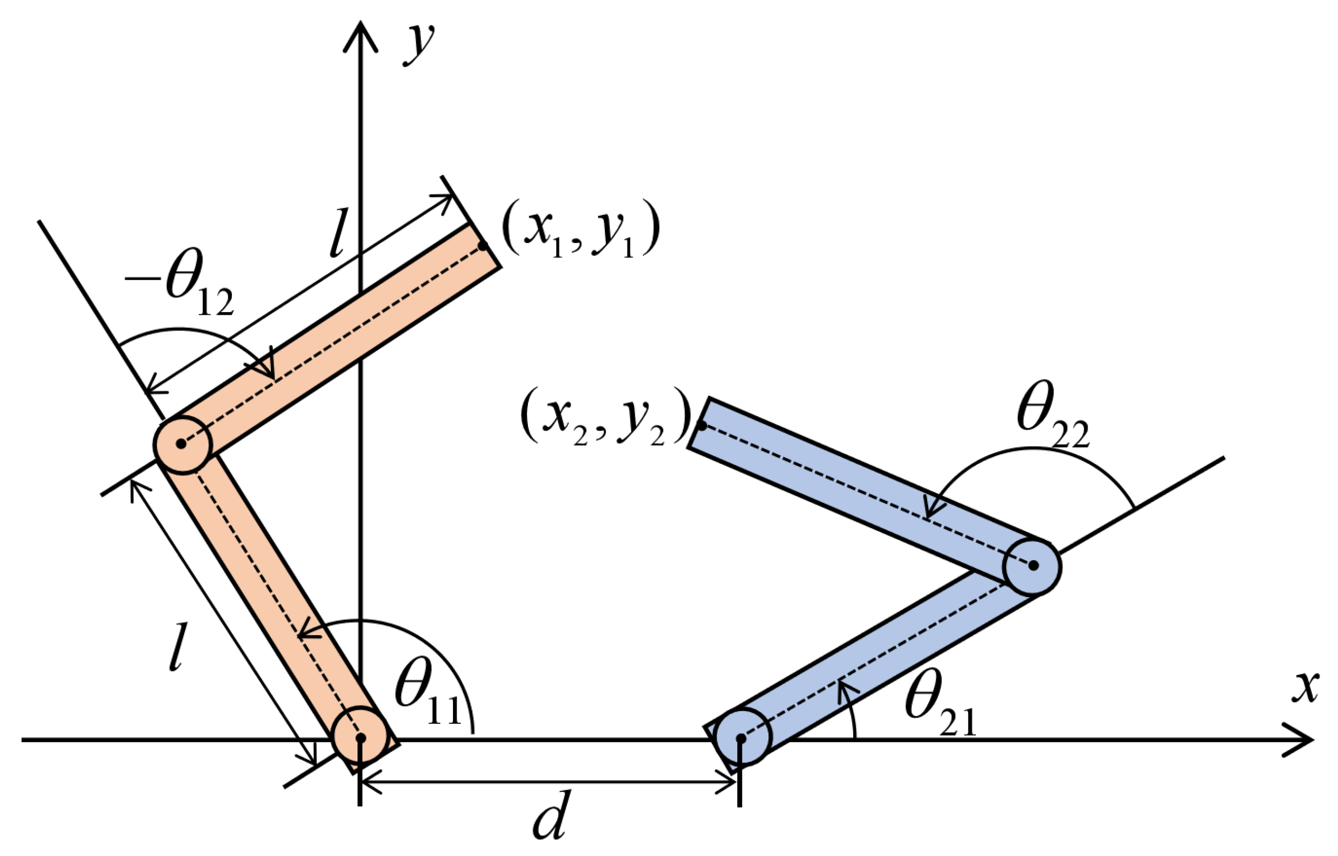
Collision avoidance is a critical safety requirement for the coordinated operation of multiple m-DOF manipulators. Taking the t w o -DOF manipulator as an example, the end-effector position in the Cartesian space is uniquely determined by the joint angles via forward kinematics:
p i ( θ i ) = x i ( θ i ) y i ( θ i ) = l i 1 cos θ i , 1 + l i , 2 cos ( θ i , 1 + θ i , 2 ) l i 1 sin θ i , 1 + l i , 2 sin ( θ i , 1 + θ i , 2 ) ,
where l i , 1 , l i , 2 are the lengths of the two links of the i-th manipulator, and p i R 2 is the end-effector coordinate in the 2D plane.
To describe the relative spatial relationship between any two manipulators and quantify the collision risk, a generalized distance function ϕ ( θ i , θ j ) is defined for manipulator i and manipulator j as the Euclidean distance between their end-effectors in the Cartesian space:
ϕ ( θ i , θ j ) = p i ( θ i ) p j ( θ j ) = ( x i x j ) 2 + ( y i y j ) 2 .
This function is designed to conform to the basic metric properties required for avoidance control, i.e., strict symmetry and gradient anti-symmetry:
ϕ ( θ i , θ j ) = ϕ ( θ j , θ i ) , ϕ ( θ i , θ j ) θ i = ϕ ( θ j , θ i ) θ j .
The partial derivative of the distance function with respect to the joint angles can be derived via the chain rule and the manipulator Jacobian matrix J i ( θ i ) = p i θ i :
ϕ θ i = ( p i p j ) T p i p j J i ( θ i ) , ϕ θ j = ( p i p j ) T p i p j J j ( θ j ) .
Based on this generalized distance function, the collision set (or unsafe region) for each pair of manipulators is defined to clearly distinguish the safe and unsafe states:
Ω i j = ( θ i , θ j ) | ϕ ( θ i , θ j ) r i j ,
where r i j is the predefined minimum safe distance between the i-th and j-th t w o -DOF manipulators. The multi-manipulator system is regarded as realizing persistent collision-free motion if and only if the joint state pair ( θ i ( t ) , θ j ( t ) ) never enters the collision set Ω i j for any t 0 , provided that the initial states are safe.
Let R i j denote the collision detection radius of the i-th manipulator, which represents the range where the avoidance control starts to take effect. The avoidance function for each manipulator pair is designed as
V i j a ( θ i , θ j ) = min 0 , ϕ ( θ i , θ j ) R i j ϕ ( θ i , θ j ) r i j 2 .
This avoidance function is non-negative, continuously differentiable almost everywhere, and satisfies (1) V i j a = 0 when ϕ > R i j ; ( 2 )   V i j a + when ϕ r i j .
The gradient of the avoidance function is derived piecewise to support the gradient-based control law design, which is given by
V i j a θ i = 2 ( R i j r i j ) ( ϕ R i j ) ( ϕ r i j ) 3 ϕ θ i , if r i j < ϕ R i j , 0 , otherwise .
By the gradient anti-symmetry of ϕ , it holds that V i j a θ i = V i j a θ j , which is critical for the passivity and stability analysis of the closed-loop system.

3.3. Control Law Design

Based on the objective function for set-point regulation and the avoidance function for collision safety established in the preceding subsections, we develop a closed-form control law for the multi m-DOF manipulator system under the gradient-based control framework, incorporating the relative-velocity-dependent modulation mechanism to achieve asymptotic convergence to the desired joint configuration while ensuring smooth, non-conservative and collision-free coordinated motion. For the i-th m-DOF manipulator, the proposed control torque is designed as
u i = k i p V i o ( θ i ) θ i u i o + j N , j i k i j a W i j a V i j a ( θ i , θ j ) θ i T j i u i j a k i v θ ˙ i + ρ i θ ˙ i θ ˙ i , θ ˙ i 0 0 , θ ˙ i = 0 u i d + u i ε
where k i p is the positive definite tracking control gain, k i j a is the symmetric pairwise avoidance control gain, k i v is the joint damping gain, and ρ i is the known upper bound of the external disturbance d i defined in the problem formulation section.
It should be noted that the proposed control law explicitly incorporates velocity information through two mechanisms. The relative-velocity-dependent weighting function W i j a adjusts the avoidance action according to the relative motion trend between manipulators, thereby reducing unnecessary avoidance behaviors and improving motion efficiency. In addition, the damping term k v θ ˙ i provides energy dissipation, suppresses oscillatory responses, and enhances the smoothness of the closed-loop motion.
The perturbation term u i ε is primarily introduced to provide a theoretical guarantee against trapping at local minima and to facilitate the Lyapunov-based stability analysis. Since the local-minimum conditions are generally difficult to satisfy in practical applications due to inevitable sensing errors, actuation errors, and external disturbances, the perturbation term is rarely activated during normal operation. Moreover, the proposed controller incorporates relative-velocity weighting and damping mechanisms, which suppress oscillatory responses and improve motion smoothness.
The first term of the control law is constructed based on the negative gradient of the objective function, which drives the joint angles of the manipulator to asymptotically converge to the desired constant configuration θ i d . According to the piecewise objective function defined previously, the gradient of V i o ( θ i ) with respect to the joint angle vector is derived piecewise as
V i o ( θ i ) θ i = k i p θ i θ i d , if   θ i θ i d μ i o k i p , μ i o θ i θ i d θ i θ i d , otherwise ,
and this gradient remains continuous at the switching boundary θ i θ i d = μ i o k i p , which ensures the continuity of the tracking control torque and avoids undesired chattering in the control input.
The core innovation of the pairwise avoidance component in the control law lies in the introduction of the relative-velocity-dependent weighting function W i j a , which addresses the over-conservatism and unnecessary actuation of traditional gradient-based avoidance methods. This weighting function is defined as
W i j a = W i j a ( θ i , θ j , θ ˙ i , θ ˙ j ) = δ i j a ϕ ( θ i , θ j ) θ i θ ˙ i j , if ϕ ( θ i , θ j ) θ i θ ˙ i j 0 , 0 , if ϕ ( θ i , θ j ) θ i θ ˙ i j > 0 ,
where δ i j a is a constant design parameter and θ ˙ i j = θ ˙ i θ ˙ j denotes the relative joint velocity between manipulator i and j . The physical meaning of this weighting function is straightforward: the term ϕ θ i θ ˙ i j characterizes the rate of change of the relative distance between the two manipulators so that when this term is non-positive, it indicates that the two manipulators are approaching each other, and the avoidance control is activated to push them apart, while when this term is positive, the two manipulators are moving away from each other, and the weighting function W i j a is set to 0 to deactivate the avoidance control regardless of the current relative distance. This design eliminates unnecessary avoidance actuation, reduces energy consumption during the coordinated motion, and allows the desired configurations of the manipulators to be located within each other’s detection radius, which is not achievable with traditional gradient-based avoidance controllers.
The joint damping term k i v θ ˙ introduces viscous damping to the joint motion, which dissipates the kinetic energy of the manipulator system, suppresses residual oscillations during the convergence process, and improves the dynamic stability of the closed-loop system while also serving as a critical component for the Lyapunov-based stability proof in the subsequent section by ensuring the negative semi-definiteness of the time derivative of the Lyapunov candidate function. The robust term with the switching structure is designed to compensate for the unknown bounded external disturbance d i , and based on the vanishing perturbation assumption that d i 0 when θ ˙ 0 , this term ensures that the disturbance is fully suppressed in the steady state without affecting the asymptotic convergence of the joint angles to the desired configuration.
Finally, to address the potential local minima (deadlock) issue inherent to gradient-based avoidance control, where the tracking control term and the avoidance control term cancel each other out and result in the manipulator being trapped at a non-desired configuration with zero joint velocity, we introduce a dedicated perturbation term designed as
u i ε = μ i ε u i a Φ ( π 2 ) u i a , if the predefined activation condition is satisfied , 0 , otherwise ,
where u i a = j N , j i k i j a W i j a V i j a ( θ i , θ j ) θ i T is the total avoidance control torque for manipulator i, μ i ε is the perturbation amplitude, and Φ ( π 2 ) R m × m is a 90-degree rotation matrix that ensures u i ε is perpendicular to u i a . The perturbation is activated when the following three conditions are satisfied: u i a 0 , u i o + u i a   k i ε , and u i a T θ ˙ i = u i a θ ˙ i , where 0 k i ε < μ i ε is a threshold parameter. This perturbation term breaks the balance between the tracking and avoidance control torques, drives the manipulator out of the local minimum, and ensures that the system can eventually converge to the desired joint configuration without permanent trapping.
It should be emphasized that the proposed controller is formulated directly in the joint space based on the Euler–Lagrange model. Unlike operational-space stiffness control approaches, the proposed method does not require dynamic linearization or inverse-dynamics cancellation in Cartesian space. The closed-loop stability is established through a generalized Lyapunov analysis for non-smooth systems.

4. Stability Analysis

In this section, we provide a rigorous Lyapunov-based stability analysis to theoretically verify that the proposed control law guarantees two core performance objectives: persistent collision-free motion among all manipulators at all times, and asymptotic convergence of each manipulator’s joint angles to the desired constant configuration θ i d . The following theorem presents the main stability result for the closed-loop multi-manipulator system.
Theorem 1.
Consider the cooperative multi m-DOF manipulator system with Lagrangian dynamics defined in Equation (2), under the proposed control law in Equation (11). Assume that the initial states of the system are safe, i.e., ( θ i ( 0 ) , θ j ( 0 ) ) Ω i j for all i , j N , j i , and the desired joint configurations satisfy ϕ ( θ i d , θ j d ) R i j for all i , j N , j i , meaning the desired states lie outside each other’s collision detection range. Then, the closed-loop system guarantees that no collision occurs between any pair of manipulators for all t 0 , and all joint angles asymptotically converge to the desired configurations, i.e., θ i ( t ) θ i d as t for all i N .
Proof. 
We first construct the following Lyapunov candidate function for the entire closed-loop multi-manipulator system, which consists of three non-negative components: the set-point regulation potential energy, the total kinetic energy of all manipulators, and the collision avoidance potential energy between all manipulator pairs:
V = i = 1 N k i p V i o ( θ i ) + 1 2 i = 1 N θ ˙ i T M i ( θ i ) θ ˙ i + 1 2 i = 1 N j N , j i δ i j a k i j a V i j a ( θ i , θ j ) ,
where δ i j a = δ j i a > 0 is the constant design parameter defined in the velocity weighting function W i j a , k i j a = k j i a > 0 is the symmetric pairwise avoidance control gain, and all other terms are consistent with the definitions in the previous sections. The stability analysis follows the Lyapunov framework presented in [32].
We first rigorously verify the non-negativity and radial unboundedness of the Lyapunov candidate function, which are the prerequisites for Lyapunov stability analysis. By property P1 of the objective function V i o ( θ i ) , V i o ( θ i ) 0 for all feasible joint configurations θ i , and k i p > 0 ; thus, the regulation potential energy is non-negative, with equality if and only if V i o ( θ i ) = 0 for all i, i.e., θ i = θ i d for all manipulators (by property P2 of the objective function). The inertia matrix M i ( θ i ) is symmetric and uniformly positive definite for all feasible θ i (by the fundamental property of the Lagrangian system). For any non-zero joint velocity vector θ ˙ i , the quadratic form θ ˙ i T M i ( θ i ) θ ˙ i > 0 and equals 0 if and only if θ ˙ i = 0 , so the total kinetic energy is non-negative for all system states. By design, the avoidance function V i j a ( θ i , θ j ) = min 0 , ϕ R i j ϕ r i j 2 is the square of a real-valued function, so V i j a 0 for all ϕ > r i j . Specifically, When ϕ > R i j , min 0 , ϕ R i j ϕ r i j = 0 , so V i j a = 0 ; When r i j < ϕ R i j , ϕ R i j ϕ r i j 0 , so V i j a = ϕ R i j ϕ r i j 2 > 0 .
Combined with δ i j a > 0 and k i j a > 0 , the collision avoidance potential energy is non-negative, with equality if and only if ϕ ( θ i , θ j ) > R i j for all i j .
Combining the above analysis, the Lyapunov candidate function satisfies V 0 for all feasible system states, and V = 0 if and only if
θ i = θ i d , θ ˙ i = 0 , ϕ ( θ i d , θ j d ) > R i j , i , j N , j i .
In addition, the Lyapunov function is radially unbounded with respect to the joint configuration error and the relative distance between manipulators: as θ i θ i d , V i o ( θ i ) , the regulation potential energy tends to infinity; as ϕ ( θ i , θ j ) r i j + (approaching the collision boundary from the safe side), V i j a + , the collision avoidance potential energy tends to infinity.
Next, we take the time derivative of V along the trajectories of the closed-loop system, applying the chain rule for differentiation term by term:
V ˙ = V ˙ p + V ˙ k + V ˙ a ,
where V ˙ p , V ˙ k and V ˙ a represent the time derivatives of the regulation potential energy, total kinetic energy and collision avoidance potential energy, respectively. We derive the time derivative of each component separately.
By the chain rule, the time derivative of the scalar function V i o ( θ i ) with respect to time is d V i o d t = V i o θ i θ ˙ i , thus:
V ˙ p = i = 1 N k i p V i o θ i θ ˙ i .
Applying the product rule for matrix differentiation to the quadratic form:
V ˙ k = d d t 1 2 i = 1 N θ ˙ i T M i θ ˙ i = 1 2 i = 1 N θ ¨ i T M i θ ˙ i + θ ˙ i T M ˙ i θ ˙ i + θ ˙ i T M i θ ¨ i .
Since M i is symmetric, θ ¨ i T M i θ ˙ i = θ ˙ i T M i θ ¨ i . Substituting this into the above equation simplifies it to
V ˙ k = i = 1 N θ ˙ i T M i θ ¨ i + 1 2 i = 1 N θ ˙ i T M i ˙ θ ˙ i .
From the simplified dynamic model in Equation (2), we have M i θ ¨ i = u i + d i C i θ ˙ i . Substitute this into the expression of V ˙ k :
V ˙ k = i = 1 N θ ˙ i T u i + d i C i θ ˙ i + 1 2 i = 1 N θ ˙ i T M ˙ i θ ˙ i .
Rearrange the terms:
V ˙ k = i = 1 N θ ˙ i T ( u i + d i ) i = 1 N θ ˙ i T C i θ ˙ i + 1 2 i = 1 N θ ˙ i T M ˙ i θ ˙ i .
By the fundamental skew-symmetric property of the Lagrangian system: the matrix M ˙ i 2 C i is skew-symmetric for all feasible system states, which means for any vector z R m , z T ( M ˙ i 2 C i ) z = 0 . Letting z = θ ˙ i , we get 1 2 θ ˙ i T M ˙ i θ ˙ i = θ ˙ i T C i θ ˙ i . Substituting this equality into V ˙ k , the Coriolis/centrifugal terms cancel out exactly:
V ˙ k = i = 1 N θ ˙ i T ( u i + d i ) .
Applying the chain rule to the double summation term of the collision avoidance potential energy, we get
V ˙ a = 1 2 i = 1 N j N , j i δ i j a k i j a V i j a θ i θ ˙ i + V i j a θ j θ ˙ j .
By the gradient anti-symmetry property of the avoidance function, we have V i j a θ j = V i j a θ i (derived from the anti-symmetry of the distance function gradient ϕ θ j = ϕ θ i ). In addition, due to the symmetry of the parameters k i j a = k j i a and δ i j a = δ j i a , the double summation can be simplified by swapping the indices i and j in the second term of the bracket. For the pairwise summation over all i j , we have
i = 1 N j i δ i j a k i j a V i j a θ j θ ˙ j = j = 1 N i j δ j i a k j i a V j i a θ i θ ˙ i = i = 1 N j i δ i j a k i j a V i j a θ i θ ˙ i .
Substituting this back into V ˙ a , we get the simplified form
V ˙ a = i = 1 N j i δ i j a k i j a V i j a θ i θ ˙ i .
Combining the derivatives of the three components, we obtain the full expression of V ˙ :
V ˙ = i = 1 N k i p V i o θ i θ ˙ i + i = 1 N θ ˙ i T ( u i + d i ) + i = 1 N j i δ i j a k i j a V i j a θ i θ ˙ i .
We now substitute the proposed control law into the above equation. Recall the full form of the control law defined in Equation (11):
u i = k i p V i o θ i + j i k i j a W i j a V i j a θ i T k i v θ ˙ i + ρ i θ ˙ i θ ˙ i , θ ˙ i 0 0 , θ ˙ i = 0 + u i ε .
Substitute u i into the V ˙ expression, and expand the summation term by term. First, substitute the control law into the kinetic energy derivative term:
i = 1 N θ ˙ i T ( u i + d i ) = i = 1 N θ ˙ i T ( k i p V i o θ i + j i k i j a W i j a ( V i j a θ i ) T k i v θ ˙ i + u i d + u i ε + d i ) .
Then, combine it with the other two terms of V ˙ , and split the overlong formula into multi-line aligned form to avoid page overflow:
V ˙ = i = 1 N k i p V i o θ i θ ˙ i + i = 1 N θ ˙ i T ( k i p V i o θ i + j i k i j a W i j a V i j a θ i T k i v θ ˙ i + u i d + u i ε + d i ) + i = 1 N j i δ i j a k i j a V i j a θ i θ ˙ i .
We simplify this expression by canceling out the matching terms and grouping the remaining terms. The first term i = 1 N k i p V i o θ i θ ˙ i cancels exactly with the tracking control term i = 1 N θ ˙ i T k i p V i o θ i , since V i o θ i θ ˙ i = θ ˙ i T V i o θ i T . After simplification, we obtain the final compact form of V ˙ :
V ˙ = i = 1 N k i v θ ˙ i 2 + i = 1 N θ ˙ i T ( u i d + d i ) + i = 1 N θ ˙ i T u i ε i = 1 N j i k i j a W i j a δ i j a V i j a θ i θ ˙ i .
We now analyze each term in the above equation separately to rigorously prove that V ˙ 0 holds for all feasible system states. The first term is the joint damping term i = 1 N k i v θ ˙ i 2 . Since the damping gain k i v > 0 and the squared norm θ ˙ i 2 0 for all θ ˙ i , this term is non-positive for all system states, with equality holding if and only if θ ˙ i = 0 for all i N .
The second term is the disturbance attenuation term i = 1 N θ ˙ i T ( u i d + d i ) , which we analyze in two cases: When θ ˙ i 0 , by definition, u i d = ρ i θ ˙ i θ ˙ i . Substitute this into the term, and apply the Cauchy–Schwarz inequality θ ˙ i T d i θ ˙ i d i :
θ ˙ i T ( u i d + d i ) = θ ˙ i T ρ i θ ˙ i θ ˙ i + θ ˙ i T d i = ρ i θ ˙ i + θ ˙ i T d i .
By the bounded disturbance assumption, d i ρ i , so
θ ˙ i T ( u i d + d i ) ρ i θ ˙ i + θ ˙ i d i = θ ˙ i d i ρ i 0 .
When θ ˙ i = 0 , by definition, u i d = 0 , and by the vanishing perturbation assumption, d i = 0 when θ ˙ i = 0 , thus θ ˙ i T ( u i d + d i ) = 0 .
In both cases, the disturbance attenuation term is non-positive for all system states.
The third term is the deadlock-breaking perturbation term i = 1 N θ ˙ i T u i ε . By design, the perturbation term u i ε is activated only when the following condition holds:
u i a 0 , u i o + u i a k i ε , u i a T θ ˙ i = u i a θ ˙ i ,
where the third equality indicates that the total avoidance control torque u i a is strictly parallel to the joint velocity θ ˙ i (with opposite direction). By definition, u i ε = u i ε u i a Φ ( π / 2 ) u i a , where Φ ( π / 2 ) is a 90-degree rotation matrix, which ensures that Φ ( π / 2 ) u i a is strictly perpendicular to u i a . Since u i a is parallel to θ ˙ i , u i ε is strictly perpendicular to θ ˙ i , so
θ ˙ i T u i ε = 0 .
When the activation condition is not satisfied, u i ε = 0 , so the dot product is also 0. Therefore, the deadlock-breaking perturbation term has no impact on the sign of V ˙ and always equals 0 for all system states.
The fourth term is the avoidance control cross term i = 1 N j i k i j a W i j a δ i j a V i j a θ i θ ˙ i . We first simplify this term using the symmetry and gradient anti-symmetry properties. For the pairwise summation over all i j , we swap the indices i and j and use k i j a = k j i a , δ i j a = δ j i a , and V i j a θ j = V i j a θ i :
i = 1 N j i k i j a W i j a δ i j a V i j a θ i θ ˙ i = 1 2 [ i = 1 N j i k i j a W i j a δ i j a V i j a θ i θ ˙ i + j = 1 N i j k j i a W j i a δ j i a V j i a θ j θ ˙ j ] = 1 2 i = 1 N j i k i j a W i j a δ i j a V i j a θ i θ ˙ i V i j a θ i θ ˙ j = 1 2 i = 1 N j i k i j a W i j a δ i j a V i j a θ i θ ˙ i j ,
where θ ˙ i j = θ ˙ i θ ˙ j is the relative joint velocity between manipulator i and j. Substituting this back into the avoidance cross term, we get
i = 1 N j i k i j a W i j a δ i j a V i j a θ i θ ˙ i = 1 2 i = 1 N j i k i j a W i j a δ i j a V i j a θ i θ ˙ i j .
We now analyze the sign of this term based on the definition of the velocity weighting function W i j a , which is divided into two cases:
-
Case 1: ϕ θ i θ ˙ i j 0 : This condition indicates that the relative distance between the two manipulators is decreasing, i.e., the manipulators are approaching each other. By definition, W i j a = δ i j a ϕ θ i θ ˙ i j in this case. Substitute W i j a into the core expression:
W i j a δ i j a V i j a θ i θ ˙ i j = ϕ θ i θ ˙ i j V i j a θ i θ ˙ i j .
For the avoidance function, when the manipulators are approaching each other ( ϕ θ i θ ˙ i j 0 ), the relative distance ϕ decreases, so the avoidance function V i j a increases, which means V i j a θ i θ ˙ i j 0 . Since k i j a > 0 , the product of the two non-positive terms is non-negative:
k i j a W i j a δ i j a V i j a θ i θ ˙ i j 0 .
-
Case 2: ϕ θ i θ ˙ i j > 0 : This condition indicates that the relative distance between the two manipulators is increasing, i.e., the manipulators are moving away from each other. By definition, W i j a = 0 in this case. Substitute W i j a = 0 into the core expression:
W i j a δ i j a V i j a θ i θ ˙ i j = δ i j a · V i j a θ i θ ˙ i j .
When the manipulators are moving away from each other ( ϕ θ i θ ˙ i j > 0 ), the relative distance ϕ increases, so the avoidance function V i j a decreases, which means V i j a θ i θ ˙ i j 0 . Since δ i j a > 0 and k i j a > 0 , the product is non-negative:
k i j a W i j a δ i j a V i j a θ i θ ˙ i j = k i j a δ i j a · V i j a θ i θ ˙ i j 0 .
In both cases, the core summation term is non-negative, so the avoidance control cross term, which is the negative of this summation, is non-positive for all system states:
1 2 i = 1 N j i k i j a W i j a δ i j a V i j a θ i θ ˙ i j 0 .
Combining the sign analysis of all four terms, we conclude that the time derivative of the Lyapunov candidate function satisfies
V ˙ 0
for all feasible system states. This proves that the closed-loop system is Lyapunov stable in the sense of Lyapunov.
We now prove the first core conclusion: persistent collision-free motion for all t 0 , using the method of contradiction. Assume that a collision occurs at some finite time t c > 0 , which means there exists a pair of manipulators i j such that ϕ ( θ i ( t c ) , θ j ( t c ) ) = r i j , i.e., the relative distance reaches the collision boundary. Since the initial state is safe ( ϕ ( θ i ( 0 ) , θ j ( 0 ) ) > r i j for all i j ), the trajectory must approach the collision boundary from the safe side, i.e., ϕ ( θ i ( t ) , θ j ( t ) ) r i j + as t t c .
By the design of the avoidance function, as ϕ r i j + , the denominator of the avoidance function tends to 0, so V i j a + . This leads to the Lyapunov function V ( t ) + as t t c . However, since V ˙ 0 for all t < t c , the Lyapunov function V ( t ) is non-increasing over time, which means V ( t ) V ( 0 ) for all t < t c , where V ( 0 ) is a finite constant determined by the initial state. This creates a contradiction: V ( t ) cannot tend to infinity while remaining bounded by V ( 0 ) .
Therefore, our initial assumption is invalid, and no collision can occur at any finite time t 0 . The system maintains persistent collision-free motion for all time.
We then prove the second core conclusion: asymptotic convergence to the desired joint configurations, by applying LaSalle’s Invariance Principle for non-smooth systems (Filippov systems). Since V ˙ 0 and V is radially unbounded, all system trajectories are bounded and remain in the compact set S = { ( θ , θ ˙ ) V ( θ , θ ˙ ) V ( 0 ) } for all t 0 .
By LaSalle’s Invariance Principle, all bounded trajectories of the system will asymptotically converge to the largest invariant set M contained in the set where V ˙ = 0 . We now characterize this largest invariant set M .
From the expression of V ˙ , V ˙ = 0 if and only if the damping term equals 0, i.e., θ ˙ i = 0 for all i N (this is the only way for the strictly negative term to be 0). The remaining terms of V ˙ are automatically 0 when θ ˙ i = 0 . Thus, the set where V ˙ = 0 is exactly the set of all states with zero joint velocity:
Z = { ( θ , θ ˙ ) θ ˙ i = 0 , i N } .
We now find the largest invariant set M contained in Z . For a state to be in the invariant set M , it must remain in Z for all future time, which means θ ˙ i 0 and θ ¨ i 0 for all i N .
Substitute θ ˙ i 0 and θ ¨ i 0 into the simplified dynamic model:
M i ( θ i ) · 0 + C i ( θ i , 0 ) · 0 = u i + d i .
By the vanishing perturbation assumption, d i = 0 when θ ˙ i = 0 , so the dynamic model reduces to
u i = 0 , i N .
Recall the full form of the control law, and substitute θ ˙ i = 0 : the damping term, disturbance attenuation term, and deadlock-breaking term all equal 0, so the control law simplifies to
u i = u i o + u i a = k i p V i o θ i + j i k i j a W i j a V i j a θ i T = 0 .
We now use the assumption that the desired joint configurations satisfy ϕ ( θ i d , θ j d ) R i j for all i j . When θ i = θ i d for all i, the relative distance between any two manipulators is greater than or equal to the detection radius R i j , so the avoidance function V i j a = 0 and its gradient V i j a θ i = 0 , so the total avoidance control term u i a = 0 . By property P2 of the objective function, V i o θ i = 0 if and only if θ i = θ i d , so the tracking control term u i o = k i p V i o θ i = 0 when θ i = θ i d , which satisfies the equilibrium condition u i = 0 .
We now prove that this is the only equilibrium point in the invariant set M . Assume there exists a non-desired equilibrium point where θ i θ i d for some i, but u i = 0 . This would require u i o = u i a 0 , which means the tracking control term is exactly canceled by the avoidance control term, creating a local minimum (deadlock). However, by the design of the deadlock-breaking perturbation term u i ε , this condition will activate the perturbation term, which injects a torque perpendicular to the avoidance control term, breaking the balance between u i o and u i a and driving the system out of the local minimum. Thus, the only persistent equilibrium point in the invariant set M is the desired joint configuration θ i = θ i d with θ ˙ i = 0 .
By LaSalle’s Invariance Principle, all system trajectories asymptotically converge to this unique equilibrium point, i.e., θ i ( t ) θ i d as t for all i N . This completes the proof. □
The two assumptions in Theorem 1 are introduced to address specific technical requirements in the Lyapunov stability analysis. The safe initial condition is a universal prerequisite for all safety-critical control methods, as no control law can recover a system from an already collided state. The assumption that desired configurations lie outside the mutual detection range ensures that the avoidance control term vanishes exactly at the equilibrium point, which is required to satisfy the conditions of LaSalle’s Invariance Principle for a rigorous asymptotic convergence proof. As discussed in the following remark, this technical assumption can be significantly relaxed in practical applications due to the velocity-dependent nature of the proposed avoidance mechanism.
Remark 1.
The assumption that the desired configurations lie outside the detection range can be relaxed in practical applications. If the desired joint configurations satisfy r i j < ϕ ( θ i d , θ j d ) < R i j (i.e., the desired states are inside the detection range but outside the collision set), the system can still converge to the desired configurations as long as the manipulators are moving away from each other when approaching the desired states. In this scenario, W i j a = 0 when the manipulators approach the desired configurations, so the avoidance control term is deactivated, and the tracking control term can drive the system to the desired states without interference from the avoidance control.

5. Examples

To verify the effectiveness of the proposed switching-based cooperative avoidance control method with relative velocity information for Lagrangian systems, this section takes dual two-DOF planar serial rigid manipulators as the simulation object to carry out cooperative obstacle avoidance and joint set-point regulation tasks. The proposed control method is derived based on a general Lagrangian dynamics framework and can be directly extended to any m-DOF serial manipulator system. The simulation results of two-DOF manipulators have typical representativeness.
It should be emphasized that the generality of the proposed method follows from the controller formulation and the accompanying stability analysis, both of which are developed for general multi-manipulator Lagrangian systems with arbitrary degrees of freedom. The dual two-DOF simulation example considered in this section is adopted solely to provide a clear and intuitive illustration of the theoretical results.

5.1. Simulation Setup

5.1.1. System Dynamics Model and Physical Parameters

Consider two two-DOF planar serial rigid manipulators with identical structures. The dynamic behavior of the i-th manipulator is fully described by the Euler–Lagrange equation:
M i ( θ i ) θ ¨ i + C i ( θ i , θ ˙ i ) θ ˙ i + G i ( θ i ) = u i + d i , i N 1 2 = { 1 , 2 }
where θ i = [ θ i 1 , θ i 2 ] T R 2 is the joint angle vector of the i-th manipulator, u i R 2 is the control torque vector applied to the two joints, d i R 2 is the unknown bounded external disturbance, M i ( θ i ) R 2 × 2 is the symmetric positive-definite inertia matrix, C i ( θ i , θ ˙ i ) R 2 × 2 is the Coriolis/centrifugal matrix characterizing velocity-dependent joint coupling, and G i ( θ i ) R 2 is the gravitational torque vector.
Since the gravitational term G i ( θ i ) can be accurately modeled and fully compensated via feedforward control in the input torque, the dynamic equation can be simplified as
M i ( θ i ) θ ¨ i + C i ( θ i , θ ˙ i ) θ ˙ i = u i + d i .
The explicit analytical expressions of the inertia matrix and Coriolis/centrifugal matrix derived from the Euler–Lagrange formulation are given by
M i θ i = α i + 2 β i cos θ i 2 γ i + β i cos θ i 2 γ i + β i cos θ i 2 γ i
C i ( θ i , θ ˙ i ) = β i sin θ i 2 θ ˙ i 2 β i sin θ i 2 θ ˙ i 1 + θ ˙ i 2 β i sin θ i 2 θ ˙ i 1 0 ,
where α i , β i , γ i > 0 are constant inertial parameters determined by the mass, length and moment of inertia of the manipulator links, defined as
α i = I i 1 + I i 2 + m i 1 l i 1 g 2 + m i 2 l i 1 2 + l i 2 g 2 , β i = m i 2 l i 1 l i 2 g , γ i = I i 2 + m i 2 l i 2 g 2 .
Here, I i 1 , I i 2 are the moments of inertia of the two links of the i-th manipulator; m i 1 , m i 2 are the link masses; l i 1 , l i 2 are the link lengths; and l i 1 g , l i 2 g are the distances from the joints to the center of mass of each link.
The physical parameters of the manipulators used in the simulation are consistent with those in the literature: link lengths l i 1 = l i 2 = 100 cm, link width w = 5 cm, link masses m i 1 = m i 2 = 1 unit, distances from joints to center of mass l i 1 g = l i 2 g = 50 cm, link moments of inertia I i 1 = I i 2 = 1 unit, and horizontal distance between the bases of the two manipulators d = 30 cm.

5.1.2. Control Task and Safety Parameters

The control task of this simulation is defined as follows: the two manipulators start from their respective initial joint configurations and simultaneously converge to the swapped target joint configurations while ensuring that the distance between their end-effectors remains not less than a predefined minimum safe distance throughout the entire motion process. The specific simulation parameters are listed as
  • Minimum safe distance: r i j = 10 cm;
  • Avoidance control activation radius: R i = 60 cm;
  • Initial joint angles:
    Manipulator 1: θ 11 ( 0 ) = 2 3 π rad, θ 12 ( 0 ) = 1 2 π rad;
    Manipulator 2: θ 21 ( 0 ) = 1 3 π rad, θ 22 ( 0 ) = 3 4 π rad;
  • Desired joint angles:
    Manipulator 1: θ 11 d = 1 3 π rad, θ 12 d = 3 4 π rad;
    Manipulator 2: θ 21 d = 2 3 π rad, θ 22 d = 1 2 π rad.

5.1.3. Control Law Design and Parameter Settings

To achieve the set-point regulation task, the following objective control law is designed:
u 1 o = k 1 p ( θ 1 θ 1 d ) , u 2 o = k 2 p ( θ 2 θ 2 d ) ,
where k i p = 100 , i N 2 . It can be verified that this objective control law satisfies the fundamental properties of non-negativity and zero gradient if and only if the target state is reached (P4-P5).
Now Choose ϕ ( θ 1 , θ 2 ) as the Euclidean distance between their end-effectors in the Cartesian space:
ϕ ( θ i , θ j ) = ( x 1 x 2 ) 2 + ( y 1 y 2 ) 2 ,
where ( x 1 , y 1 ) and ( x 2 , y 2 ) are the end-effector coordinates of Manipulator 1 and Manipulator 2, respectively, determined by the forward kinematics equations:
x 1 = l 11 cos ( θ 11 ) + l 12 cos ( θ 11 + θ 12 ) , y 1 = l 11 sin ( θ 11 ) + l 12 sin ( θ 11 + θ 12 ) , x 2 = l 21 cos ( θ 21 ) + l 22 cos ( θ 21 + θ 22 ) + d , y 2 = l 21 sin ( θ 21 ) + l 22 sin ( θ 21 + θ 22 ) .
This distance function satisfies strict symmetry ϕ ( θ i , θ j ) = ϕ ( θ j , θ i ) and gradient anti-symmetry ϕ θ i = ϕ θ j , which is the basis for the design of avoidance control.
The complete control law parameters used in the simulation are as follows: joint damping gain: k i v = 1000 , pairwise avoidance control gain: k i j a = 0.5 , velocity weighting coefficient: δ i j = 0.1 .
Since the effect of external disturbances is not considered in this simulation, the disturbance compensation term u i d = 0 . Meanwhile, by reasonably designing the initial conditions and control parameters, the system will not fall into a local minimum (deadlock) state, so the deadlock-breaking perturbation term u i ε = 0 . All simulations are completed in the MATLAB/Simulink (2022b) environment using the Runge–Kutta solver with a simulation time step of 0.01 s and a total simulation duration of 800 time steps.

5.2. Simulation Results and Analysis

5.2.1. Joint Angle Convergence Characteristics

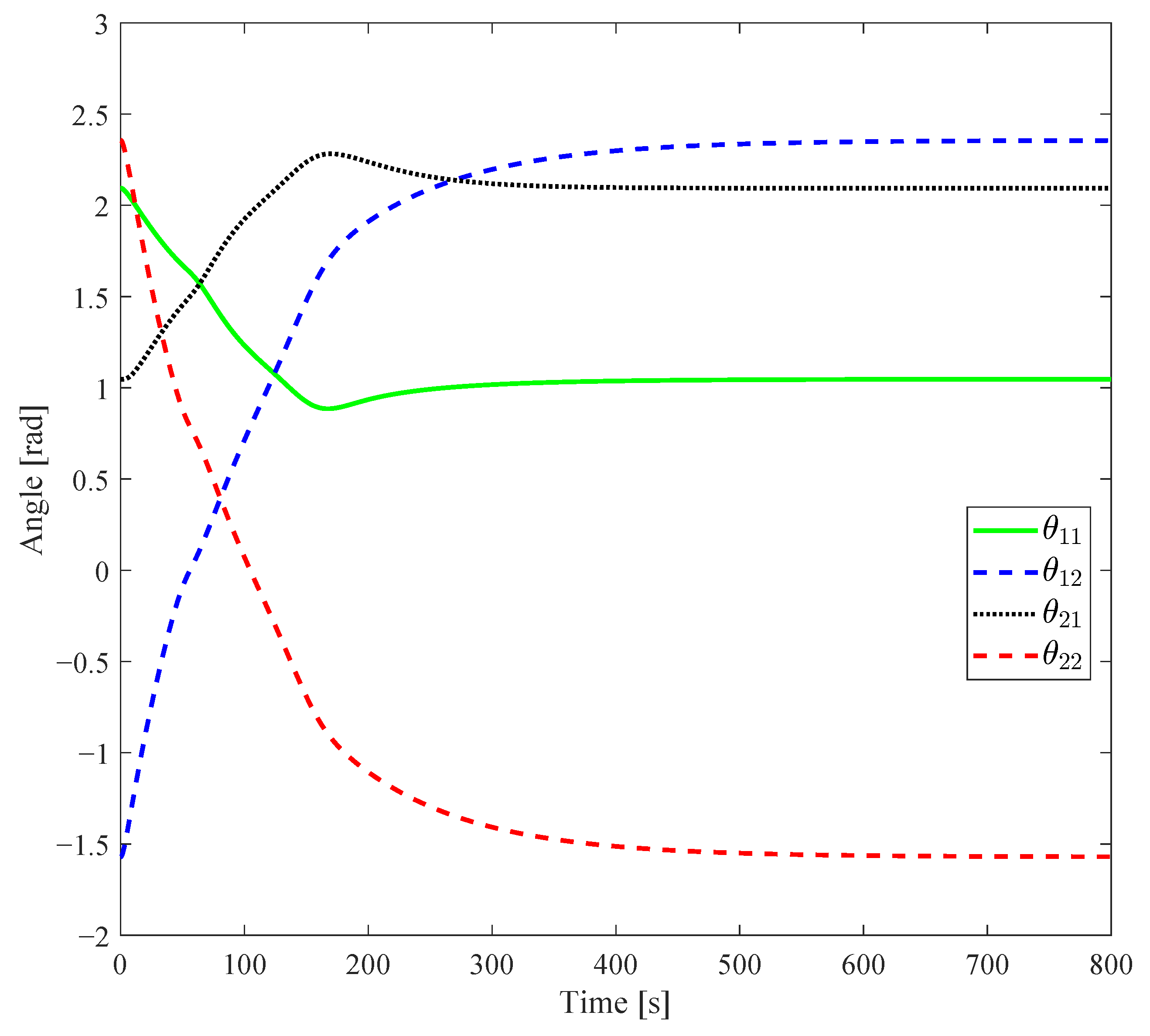
Figure 1 shows the time evolution of the four joint angles of the two manipulators under the proposed control method.
As can be seen from Figure 2, all joint angle curves are smooth and continuous without obvious oscillations or abrupt changes. Within approximately 800 time steps, all four joint angles smoothly converge to their respective target values while maintaining good dynamic characteristics during the convergence process. This indicates that the proposed control method can effectively coordinate target tracking and avoidance control, achieving precise regulation of joint angles while ensuring safety.

5.2.2. End-Effector Motion Trajectories

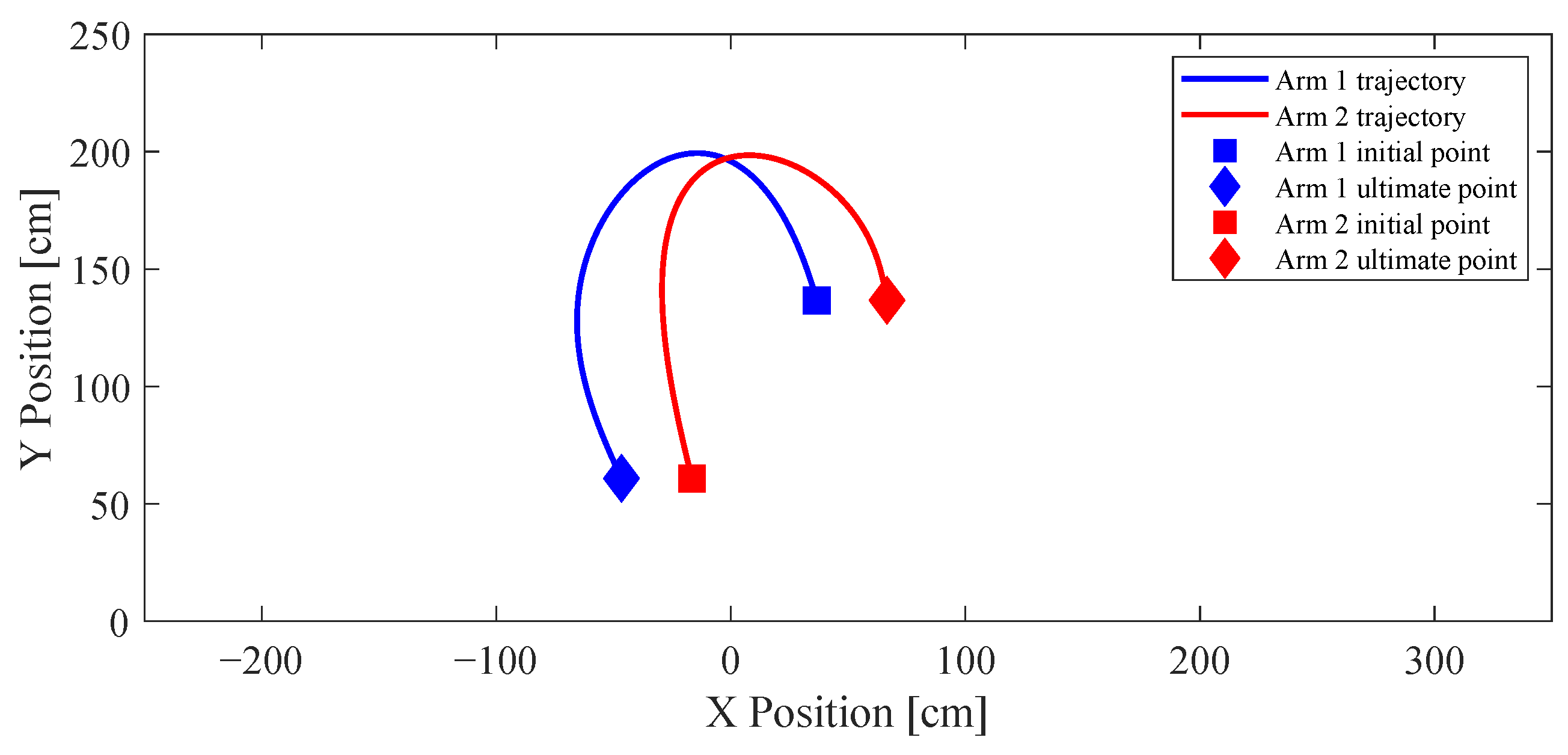
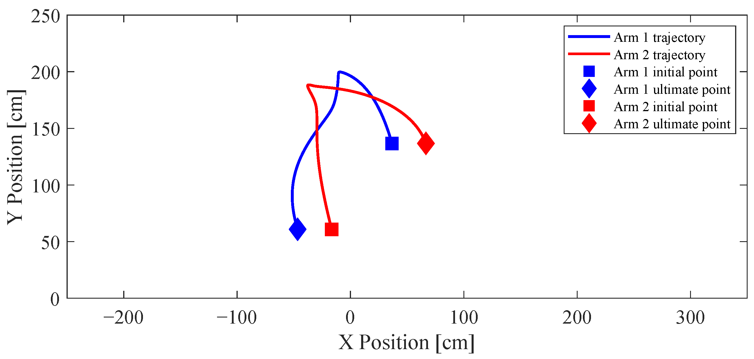
To intuitively demonstrate the effectiveness of the proposed avoidance control strategy, we compare the end-effector motion trajectories of the dual manipulator system with and without the avoidance control term, as shown in Figure 3 and Figure 4.
Figure 3 shows the end-effector trajectories when only the objective tracking control is applied. It can be seen that the two manipulators move directly towards the swapped target positions along the shortest path, and the two trajectories intersect in the middle of the workspace. Without avoidance constraints, the ends of the two manipulators will enter within the minimum safe distance during the motion, resulting in a collision and failing to complete the safe cooperative task.
Figure 4 shows the end-effector trajectories after adding the proposed switching-based avoidance control with relative velocity information. The simulation results show that the two manipulators still move towards the target direction in the initial stage. When they approach each other to the avoidance activation radius, the avoidance control is automatically activated, driving the two manipulators to generate a small necessary lateral offset, which smoothly separates the end-effector trajectories without any intersection throughout the process. After the avoidance is completed and the relative distance gradually increases, the avoidance control is automatically deactivated, and the manipulators quickly return to the target direction, finally converging to their respective target positions accurately. During the entire motion process, the end-effector trajectories are continuous and smooth without obvious large detours or oscillations, which maximizes the efficiency of target tracking while ensuring absolute safety.
It is worth noting that the apparent intersection of the two end-effector trajectories in Figure 4 does not correspond to a physical collision. Figure 4 only illustrates the geometric paths traced by the manipulators in the Cartesian workspace and does not explicitly contain temporal information. Therefore, two trajectories may visually intersect even though the corresponding end-effectors pass through the same spatial location at different time instants.
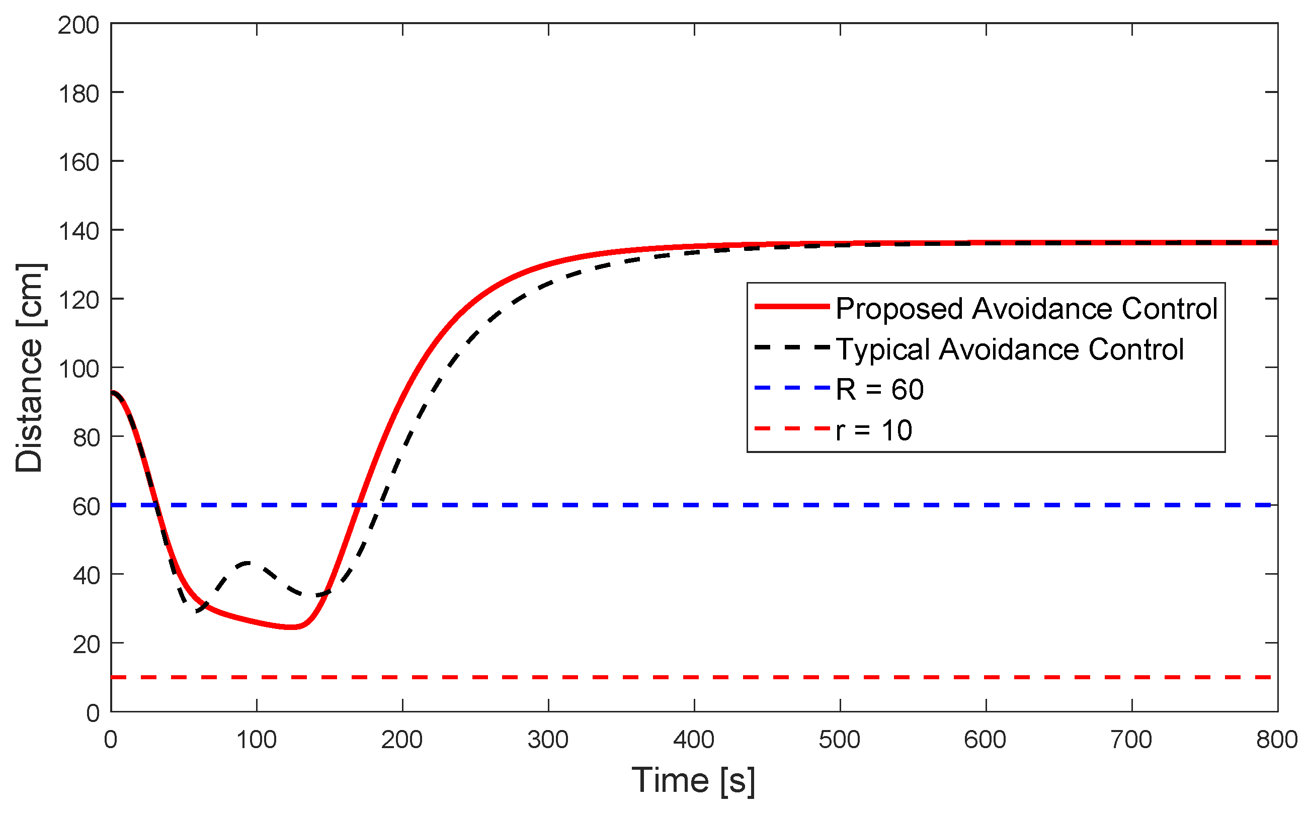
To further verify the collision-free property, Figure 5 presents the time evolution of the relative distance between the two manipulators. As shown in Figure 5, the inter-manipulator distance always remains greater than the prescribed safety threshold r 12 = 10 cm throughout the entire maneuver. This confirms that the apparent trajectory crossing observed in Figure 4 is merely a path-crossing phenomenon rather than an actual collision event. Therefore, the proposed controller successfully guarantees collision-free motion while allowing the manipulators to efficiently reach their desired configurations.

5.2.3. End-Effector Relative Distance and Avoidance Safety

Figure 5 compares the time evolution of the relative distance between the end-effectors under the proposed avoidance control and a typical avoidance control (artificial potential function-based method).
It can be observed that both controllers maintain the relative distance above the prescribed safety threshold r = 10 cm throughout the motion, thereby guaranteeing collision-free operation. However, the proposed avoidance control exhibits a smoother distance profile with fewer fluctuations during the avoidance process, indicating a more stable avoidance behavior.
Furthermore, compared with the typical avoidance control, the proposed method allows the relative distance to remain closer to the safety boundary while still ensuring collision avoidance. This indicates a less conservative avoidance behavior, leading to more efficient motion and smaller deviations from the desired trajectories. These results demonstrate the effectiveness of the proposed relative-velocity-based avoidance strategy.

5.2.4. End-Effector Velocity Characteristics

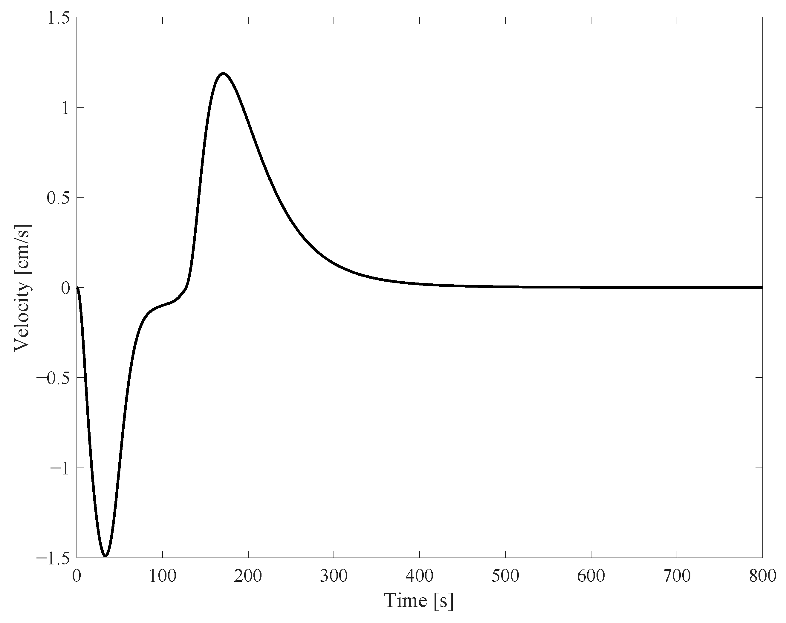
Figure 6 shows the time evolution of the end-effector velocities of the two manipulators under the proposed method.
As can be seen from Figure 6, the end-effector velocity curves are smooth, with only small adjustments during the avoidance process and no obvious velocity abrupt changes or oscillations. After approximately 800 time steps, the end-effector velocities gradually decay to zero, and the manipulators stabilize at the target configuration. This ensures the smoothness of the manipulator motion and positioning accuracy, avoiding mechanical structure fatigue damage caused by velocity fluctuations.

5.3. Simulation Summary

Based on the above simulation results, the proposed switching-based cooperative avoidance control method with relative velocity information exhibits excellent performance in the dual two-DOF manipulator system:
  • Absolute Safety: Throughout the motion process, the relative distance between the end-effectors of the two manipulators is always greater than the minimum safe distance, without any collision risk, verifying the conclusion about system safety in the theoretical analysis;
  • Low Conservatism: The avoidance control is only activated when the manipulators are approaching each other and there is a collision risk, avoiding unnecessary detours and significantly improving task execution efficiency;
  • Smoothness: The joint angles, end-effector trajectories, and control inputs are all continuous and smooth without oscillations or abrupt changes, ensuring the dynamic stability of the system;
  • Low Energy Consumption: The avoidance control is activated on demand, and the amplitude changes smoothly, effectively reducing the energy consumption of the system and actuator wear.
These results fully verify the effectiveness and superiority of the proposed control strategy, providing a reliable solution for cooperative avoidance control of multi-degree-of-freedom manipulator systems.

6. Conclusions

This paper develops a collision avoidance control strategy with relative velocity information for cooperative multi-manipulator systems with Lagrangian dynamics. This methodology yields a closed-form solution, is easy to implement in engineering practice, and can lead to smoother, less oscillatory trajectories with lower energy consumption compared to typical potential-based methods. The proposed framework integrates collision avoidance, disturbance attenuation, and deadlock elimination into a unified control architecture, and the asymptotic convergence and persistent collision-free property are rigorously proved via generalized Lyapunov stability theory. Simulation results on a dual two-DOF manipulator system verify the effectiveness and reliability of the proposed strategy.
Notably, the current collision model is simplified to end-effector distance only to focus on validating the core relative-velocity-based avoidance mechanism. The proposed control framework is built on a generalized distance-function design whose core principles are completely independent of the specific form of the distance metric. Therefore, extending the method to full link-level collision avoidance is theoretically straightforward: it only requires defining appropriate distance functions for each pair of links between different manipulators and summing the corresponding avoidance terms in the control law.
Future work will focus on four main directions: (1) experimental validation of the proposed control strategy on actual multi-manipulator platforms; (2) development of a comprehensive link-level collision detection module to extend the method from end-effector-based avoidance to full-structure safety guarantees; (3) design of adaptive and robust control strategies to address model uncertainties, parameter variations, and unmodeled friction effects; and (4) validation of the proposed framework in higher-dimensional multi-manipulator systems and complex three-dimensional cooperative scenarios to further demonstrate its scalability and applicability to general m-DOF manipulators.

Author Contributions

Conceptualization, W.Z. and Z.M.; methodology, W.Z. and Z.M.; validation, N.Z.; formal analysis, W.Z., Z.M. and D.M.S.; investigation, Z.M. and N.Z.; writing—original draft preparation, Z.M.; writing—review and editing, W.Z., D.M.S. and N.Z.; supervision, W.Z. and N.Z.; project administration, W.Z. All authors have read and agreed to the published version of the manuscript.

Funding

This research was funded by the Science and Technology Program of Hebei, grant number 23311806D, and the Hebei Higher Education Young Top Talent Program, grant number BJ2025223.

Institutional Review Board Statement

Not applicable.

Informed Consent Statement

Not applicable.

Data Availability Statement

Data are contained within the article.

Conflicts of Interest

The authors declare no conflict of interest.

References

  1. Olfati-Saber, R. Consensus and cooperation in networked multi-agent systems. Proc. IEEE 2007, 95, 215–233. [Google Scholar] [CrossRef]
  2. Fax, J.A.; Murray, R.M. Information flow and cooperative control of vehicle formations. IEEE Trans. Autom. Control 2004, 49, 1465–1476. [Google Scholar] [CrossRef]
  3. Ren, W.; Beard, R.W. Distributed Consensus in Multi-Vehicle Cooperative Control; Springer: London, UK, 2008. [Google Scholar]
  4. Cao, Y.; Yu, W.; Ren, W.; Chen, G. An Overview of Recent Progress in the Study of Distributed Multi-Agent Coordination. IEEE Trans. Ind. Inform. 2013, 9, 427–438. [Google Scholar] [CrossRef]
  5. Mesbahi, M.; Egerstedt, M. Graph Theoretic Methods in Multiagent Networks; Princeton University Press: Princeton, NJ, USA, 2010. [Google Scholar]
  6. Ames, A.D.; Grizzle, J.W.; Tabuada, P. Control barrier function based quadratic programs for safety critical systems. IEEE Trans. Autom. Control 2017, 62, 3861–3876. [Google Scholar] [CrossRef]
  7. Ames, A.D.; Coogan, S.; Egerstedt, M.; Notomista, G.; Sreenath, K.; Tabuada, P. Control Barrier Functions: Theory and Applications. In Proceedings of the 18th European Control Conference (ECC), Naples, Italy, 25–28 June 2019; pp. 3420–3431. [Google Scholar]
  8. Nguyen, Q.; Sreenath, K. Exponential control barrier functions for enforcing high relative-degree safety-critical constraints. In Proceedings of the 2016 American Control Conference (ACC), Boston, MA, USA, 6–8 July 2016; pp. 322–328. [Google Scholar]
  9. Ferraguti, F.; Landi, C.T.; Singletary, A.; Lin, H.C.; Ames, A.D.; Secchi, C.; Bonfè, M. Safety and Efficiency in Robotics: The Control Barrier Functions Approach. IEEE Robot. Autom. Mag. 2022, 29, 139–151. [Google Scholar] [CrossRef]
  10. Ames, A.D.; Notomista, G.; Wardi, Y.; Egerstedt, M. Integral Control Barrier Functions for Dynamically Defined Control Laws. IEEE Control Syst. Lett. 2021, 5, 887–892. [Google Scholar] [CrossRef]
  11. Khatib, O. Real-time obstacle avoidance for manipulators and mobile robots. Int. J. Robot. Res. 1986, 5, 90–98. [Google Scholar] [CrossRef]
  12. Koren, Y.; Borenstein, J. Potential field methods and their inherent limitations. In Proceedings of the 1991 IEEE International Conference on Robotics and Automation, Sacramento, CA, USA, 9–11 April 1991; pp. 1398–1404. [Google Scholar]
  13. Ge, S.S.; Cui, Y.J. Dynamic motion planning using potential field method. Auton. Robot. 2002, 13, 207–222. [Google Scholar] [CrossRef]
  14. Sánchez-Ibáñez, J.R.; Pérez-del-Pulgar, C.J.; García-Cerezo, A. Path Planning for Autonomous Mobile Robots: A Review. Sensors 2021, 21, 7898. [Google Scholar] [CrossRef] [PubMed]
  15. Lu, B.; He, H.; Yu, H.; Wang, H.; Li, G.; Shi, M.; Cao, D. Hybrid Path Planning Combining Potential Field with Sigmoid Curve for Autonomous Driving. Sensors 2020, 20, 7197. [Google Scholar] [CrossRef] [PubMed]
  16. Xing, T.; Wang, X.; Ding, K.; Ni, K.; Zhou, Q. Improved Artificial Potential Field Algorithm Assisted by Multisource Data for AUV Path Planning. Sensors 2023, 23, 6680. [Google Scholar] [CrossRef] [PubMed]
  17. Xia, X.; Li, T.; Sang, S.; Cheng, Y.; Ma, H.; Zhang, Q.; Yang, K. Path Planning for Obstacle Avoidance of Robot Arm Based on Improved Potential Field Method. Sensors 2023, 23, 3754. [Google Scholar] [CrossRef] [PubMed]
  18. Duan, Y.; Yang, C.; Zhu, J.; Meng, Y.; Liu, X. Active Obstacle Avoidance Method of Autonomous Vehicle Based on Improved Artificial Potential Field. Int. J. Adv. Robot. Syst. 2022, 19, 17298806221115984. [Google Scholar] [CrossRef]
  19. Zhang, L.; Mou, J.; Chen, P.; Li, M. Path Planning for Autonomous Ships: A Hybrid Approach Based on Improved APF and Modified VO Methods. J. Mar. Sci. Eng. 2021, 9, 761. [Google Scholar] [CrossRef]
  20. Azmi, M.Z.; Ito, T. Artificial Potential Field with Discrete Map Transformation for Feasible Indoor Path Planning. Appl. Sci. 2020, 10, 8987. [Google Scholar] [CrossRef]
  21. Mayne, D.Q.; Rawlings, J.B.; Rao, C.V.; Scokaert, P.O.M. Constrained model predictive control: Stability and optimality. Automatica 2000, 36, 789–814. [Google Scholar] [CrossRef]
  22. Rawlings, J.B.; Mayne, D.Q. Model Predictive Control: Theory and Design; Nob Hill Publishing: Madison, WI, USA, 2009. [Google Scholar]
  23. Chen, H.; Allgöwer, F. A Quasi-Infinite Horizon Nonlinear Model Predictive Control Scheme with Guaranteed Stability. Automatica 1998, 34, 1205–1217. [Google Scholar] [CrossRef]
  24. Liu, C.; Tomizuka, M. Safe control using model predictive control and control barrier functions. IEEE Control Syst. Lett. 2021, 5, 1742–1747. [Google Scholar] [CrossRef]
  25. Saravanos, A.D.; Balci, I.M.; Bakolas, E.; Theodorou, E.A. Distributed Model Predictive Covariance Steering. arXiv 2022, arXiv:2212.00398. [Google Scholar]
  26. Mnih, V.; Kavukcuoglu, K.; Silver, D.; Rusu, A.A.; Veness, J.; Bellemare, M.G.; Graves, A.; Riedmiller, M.; Fidjeland, A.K.; Ostrovski, G.; et al. Human-level control through deep reinforcement learning. Nature 2015, 518, 529–533. [Google Scholar] [CrossRef] [PubMed]
  27. Lillicrap, T.P.; Hunt, J.J.; Pritzel, A.; Heess, N.; Erez, T.; Tassa, Y.; Silver, D.; Wierstra, D. Continuous control with deep reinforcement learning. arXiv 2015, arXiv:1509.02971. [Google Scholar]
  28. Lowe, R.; Wu, Y.; Tamar, A.; Harb, J.; Abbeel, P.; Mordatch, I. Multi-agent actor-critic for mixed cooperative-competitive environments. In Proceedings of the 31st Conference on Neural Information Processing Systems (NIPS 2017), Long Beach, CA, USA, 4–9 December 2017. [Google Scholar]
  29. Rashid, T.; Samvelyan, M.; de Witt, C.S.; Farquhar, G.; Foerster, J.; Whiteson, S. QMIX: Monotonic value function factorisation for deep multi-agent reinforcement learning. In Proceedings of the 35th International Conference on Machine Learning, Stockholm, Sweden, 10–15 July 2018. [Google Scholar]
  30. Schulman, J.; Wolski, F.; Dhariwal, P.; Radford, A.; Klimov, O. Proximal policy optimization algorithms. arXiv 2017, arXiv:1707.06347. [Google Scholar]
  31. Slotine, J.J.E.; Li, W. Applied Nonlinear Control; Prentice Hall: Hoboken, NJ, USA, 1991. [Google Scholar]
  32. Shevitz, D.; Paden, B. Lyapunov stability theory of nonsmooth systems. IEEE Trans. Autom. Control 1994, 39, 1910–1914. [Google Scholar] [CrossRef]
  33. Fiorini, P.; Shiller, Z. Motion Planning in Dynamic Environments Using Velocity Obstacles. Int. J. Robot. Res. 1998, 17, 760–772. [Google Scholar] [CrossRef]
  34. van den Berg, J.; Lin, M.; Manocha, D. Reciprocal Velocity Obstacles for Real-Time Multi-Agent Navigation. In Proceedings of the IEEE International Conference on Robotics and Automation, Pasadena, CA, USA, 19–23 May 2008; pp. 327–332. [Google Scholar]
  35. Richards, A.; How, J.P. Decentralized Model Predictive Control of Cooperating UAVs. In Proceedings of the 43rd IEEE Conference on Decision and Control, Atlantis, Paradise Island, Bahamas, 14–17 December 2004; pp. 4286–4291. [Google Scholar]
  36. Olfati-Saber, R.; Murray, R.M. Consensus Problems in Networks of Agents with Switching Topology and Time-Delays. IEEE Trans. Autom. Control 2004, 49, 1520–1533. [Google Scholar] [CrossRef]
  37. Dimarogonas, D.V.; Frazzoli, E.; Johansson, K.H. Distributed Event-Triggered Control for Multi-Agent Systems. IEEE Trans. Autom. Control 2012, 57, 1291–1297. [Google Scholar] [CrossRef]
  38. Snape, J.; van den Berg, J.; Guy, S.J.; Manocha, D. The Hybrid Reciprocal Velocity Obstacle. IEEE Trans. Robot. 2011, 27, 696–706. [Google Scholar] [CrossRef]
  39. Keviczky, T.; Borrelli, F.; Fregene, K.; Godbole, D.; Balas, G. Decentralized Receding Horizon Control and Coordination of Autonomous Vehicle Formations. IEEE Trans. Control Syst. Technol. 2008, 16, 19–33. [Google Scholar] [CrossRef]
  40. Venkat, A.N.; Rawlings, J.B.; Wright, S.J. Stability and Optimality of Distributed Model Predictive Control. In Proceedings of the 44th IEEE Conference on Decision and Control and European Control Conference, Seville, Spain, 12–15 December 2005; pp. 6680–6685. [Google Scholar]
  41. Dai, B.; Khorrambakht, R.; Krishnamurthy, P.; Gonçalves, V.; Tzes, A.; Khorrami, F. Safe navigation and obstacle avoidance using differentiable optimization based control barrier functions. arXiv 2023, arXiv:2304.08586. [Google Scholar]
  42. Huang, J.; Liu, Z.; Zeng, J.; Chi, X.; Su, H. Obstacle avoidance for unicycle-modelled mobile robots with time-varying control barrier functions. arXiv 2023, arXiv:2307.08227. [Google Scholar]
  43. Shi, K.-G.; Hu, G. Safety-Guaranteed and Task-Consistent Human-Robot Interaction Using High-Order Time-Varying Control Barrier Functions and Quadratic Programs. IEEE Robot. Autom. Lett. 2024, 9, 547–554. [Google Scholar] [CrossRef]
  44. Ali, M.M.; Shen, C.; Hashim, H.A. A Linear MPC with Control Barrier Functions for Differential Drive Robots. arXiv 2024, arXiv:2404.10018. [Google Scholar]
  45. Zhang, S.; Garg, K.; Fan, C. Neural Graph Control Barrier Functions Guided Distributed Collision-avoidance Multi-agent Control. arXiv 2023, arXiv:2311.13014. [Google Scholar]
Figure 1. Two-link manipulators.
Jsan 15 00047 g001
Figure 2. Joint angles of two arms.
Jsan 15 00047 g002
Figure 3. Trajectories without avoidance control term.
Jsan 15 00047 g003
Figure 4. Trajectories with avoidance control term.
Jsan 15 00047 g004
Figure 5. Relative distance of links’ end points.
Jsan 15 00047 g005
Figure 6. Relative velocity of links’ end points.
Jsan 15 00047 g006
Disclaimer/Publisher’s Note: The statements, opinions and data contained in all publications are solely those of the individual author(s) and contributor(s) and not of MDPI and/or the editor(s). MDPI and/or the editor(s) disclaim responsibility for any injury to people or property resulting from any ideas, methods, instructions or products referred to in the content.