Article

A Network Architecture and Routing Protocol for the MEDIcal WARNing System

Department of Electrical, Electronic and Computer Engineering, University of Catania, 95124 Catania, Italy
*
Author to whom correspondence should be addressed.
J. Sens. Actuator Netw. 2021, 10(3), 44; https://doi.org/10.3390/jsan10030044
Submission received: 6 May 2021 / Revised: 24 June 2021 / Accepted: 25 June 2021 / Published: 30 June 2021

Abstract

:
The MEDIcal WARNing (MEDIWARN) system continuously and automatically monitors the vital parameters of pre-intensive care hospitalized patients and, thanks to an intelligent processing system, provides the medical teams with a better understanding of their patients’ clinical condition, thus enabling a prompt reaction to any change. Since the hospital units generally lack a wired infrastructure, a wireless network is required to collect sensor data in a server for processing purposes. This work presents the MEDIWARN communication system, addressing both the network architecture and a simple, lightweight and configurable routing protocol that fits the system requirements, such as the ability to offer path redundancy and mobility support without significantly increasing the network workload and latency. The novel protocol, called the MultiPath Routing Protocol for MEDIWARN (MP-RPM), was therefore designed as a solution to support low-latency reliable transmissions on a dynamic network while limiting the network overhead due to the control messages. The paper describes the MEDIWARN communication system and addresses the experimental performance evaluation of an implementation in a real use-case scenario. Moreover, the work discusses a simulative assessment of the MEDIWARN communication system performance obtained using different routing protocols. In particular, the timeliness and reliability results obtained by the MP-RPM routing protocol are compared with those obtained by two widely adopted routing protocols, i.e., the Ad-hoc On-demand Distance Vector (AODV) and the Destination-Sequenced Distance-Vector Routing (DSDV).

1. Introduction

The study and analysis of vital parameters of hospitalized patients are extremely important in clinical medicine [1], and multiple research projects aim to use novel technologies to support clinical practice [2]. As a result, several methodologies and solutions that exploit such technologies have been recently proposed [3,4] for the diagnosis of illnesses and pathologies in patients. In particular, the evolution of the patient condition in the pre-intensive care unit is essential to ensure early and prompt reaction on critical patients who could experience a progressive clinical deterioration. For this reason, the continuous monitoring of the patients’ vital signs (e.g., body temperature, blood pressure, respiratory rate, oxygen saturation, etc.) is needed [2,5,6]. Typically, such data can be obtained using sensors and other medical instrumentations [7].
In this context, the MEDIcal WARNing (MEDIWARN) system, developed in the MEDIWARN European Project (https://mediwarn.net, accessed on 29 June 2021), discussed in ref. [8]), is a novel solution able to predict a possible medical alert and warn about the deterioration of the patients’ condition. MEDIWARN realizes a system for the continuous and automated monitoring of the vital parameters of patients through the use of a peripheral sensory system that feeds into an intelligent warning system. The collected data are sent to a central station and analyzed in real time. Such an analysis, which includes mathematical models and advanced fuzzy logic (that exploits specific rules based on medical expertise), provides interpretative elements on the clinical status of patients and its evolution well before the actual deterioration of the vital functions that would trigger the alert according to solutions such as the Early Warning Score (EWS) [9] criteria. Hence, by alerting medical staff when a patient would be starting to get worse, the MEDIWARN system allows earlier intervention with a higher chance of success in treating a patient.
The use of such a system requires a network infrastructure in the hospital that would allow the transfer of data from the sensors to a server for subsequent processing. In particular, as the hospital units may lack a wired infrastructure, a wireless network is typically required. The introductory work in ref. [10] briefly presents the MEDIWARN network architecture and discusses some design challenges that such a system poses. Moreover, it shows the results of simulative assessments in realistic scenarios to provide a preliminary evaluation of the system.
This paper is meant to significantly extend the work in ref. [10]. In fact, the brief paper [10] simply overviews the MEDIWARN network architecture without exploring how to address each design challenge in a real implementation, and therefore it does not provide any performance assessment on Commercial-Off-The-Shelves (COTS) devices. Moreover, the simulative results in ref. [10] highlight the need for designing a custom routing protocol for MEDIWARN able to reduce the overhead due to the routing control messages.
This work therefore focuses on the MEDIWARN communication system. In particular, it addresses: (i) the network architecture; and (ii) a novel routing protocol specifically devised for the MEDIWARN system, which is simple, lightweight and configurable. Specifically, such a protocol provides the MEDIWARN system with path redundancy and mobility support without significantly increasing the network workload and latency. The paper offers both experimental and simulative performance evaluation of the MEDIWARN communication system in a real use-case scenario.
The main contributions of the paper are:
  • The detailed design of the MEDIWARN network architecture, a clear description of the role of each component involved in the MEDIWARN communication system and the description of a novel lightweight routing protocol, called the MultiPath Routing Protocol for MEDIWARN (MP-RPM), which offers path redundancy and mobility support without significantly increasing the network workload and latency, are presented.
  • The implementation of the MEDIWARN communication system on COTS devices is described, which shows the feasibility of the proposed network architecture and offers an experimental performance evaluation in a use case scenario.
  • The simulative assessment of the MEDIWARN communication system performance in the same scenario used for evaluating the implemented use case is presented to assess to what extent the simulative results and the experimental ones correspond.
  • A comparative assessment of the timeliness and reliability results obtained by the MEDIWARN communication system using three different routing protocols, i.e., the MP-RPM presented here, the AODV [11] (an on-demand protocol) and the DSDV [12] (a proactive protocol), is presented to highlight the impact of the routing protocol on the MEDIWARN communication system performance.
The paper is organized as follows. Section 2 deals with related works. Section 3 presents the MEDIWARN communication system. Section 4 discusses the relevant research challenges and the solutions, while Section 5 focuses on the MP-RPM routing protocol. Section 6 addresses an implementation of the MEDIWARN system on COTS devices and discusses the results obtained through an experimental evaluation. Section 7 presents a simulative evaluation of the MEDIWARN communication system. Finally, Section 8 gives conclusions and hints for future works.

2. Related Work

Nowadays, healthcare experts and researchers promote the need for automated health monitoring devices to enhance the patients’ safety and to reduce the stress of the medical staff, enabling them to monitor their patients or interactive with them from anywhere at anytime [13,14,15]. Consequently, several recent works have addressed medical monitoring systems. Moreover, to better diagnose, forecast and characterize individuals’ health, several models exploit machine learning in healthcare, as discussed in refs. [16,17,18].
In ref. [19], the authors presented an IoT-based health monitoring approach in which medical sensor data are collected and sent to an analysis module through a LoRaWAN network infrastructure. LoRaWAN represents a valid and easy-to-deploy technology for monitoring patients in field hospitals during emergency situations, as explained in ref. [20]. However, although LoRa is an appealing technology to provide low power, long-range wireless connection [21,22,23], LoRa-based approaches, e.g., the one in ref. [24], cannot cope with monitoring applications that require high sample rates and a significant amount of exchanged data. This is because LoRa is intended for low data rate transmissions and is subject to duty-cycle restrictions, and therefore it cannot support the transmission of waveforms that entail a considerable amount of data sent per second.
WiFi offers higher bandwidth than LoRa, and therefore it is a more suitable technology for the addressed purpose. The work in ref. [25] proposed a full Internet-based architecture that uses the oneM2M and openEHR standards, thus allowing interoperability between different devices and software from the WiFi-enabled wearable physiological sensors to the monitoring system. The work in ref. [26] presented a monitoring system made up of Raspberry Pi single-board computers that collect sensor data and send them through the Internet using Ethernet or WiFi. Other approaches for healthcare applications exploit the Software-Defined Networking (SDN) paradigm that, as discussed in ref. [27], allows handling the complexity of heterogeneous networks in a simple way and to provide priority-based mechanisms for the monitoring services [28,29]. For example, the architecture proposed in [30] exploits different functional and security applications and services provided by SDN.
Ref. [31] proposed a novel framework for the analysis of the human physiological detection system based on a biosensor, but it does not focus on communication aspects.
One common feature of all the approaches discussed above as well as other ones (see, e.g., [32,33,34]) is that they are Internet-based. Conversely, one of the design requirements of the MEDIWARN system was to transmit sensitive data through a private network that is locally managed within the hospital, thus avoiding to transmit them to external servers. Moreover, to the best of the authors’ knowledge, the above-mentioned state-of-the-art monitoring systems do not foresee a predictive approach able to anticipate the upcoming deterioration of a patient’s condition and trigger alarms well before the patient starts to get worse.
Conversely, MEDIWARN is intended for automatically monitoring the vital parameters of hospitalized patients in order to both take action in a proactive way whenever needed and provide a complete history of each patient’s vital parameters during their hospitalization for data analysis. For this reason, in the following, the design and implementation of a communication system that is able to cope with all the MEDIWARN requirements is addressed.

3. Network Architecture

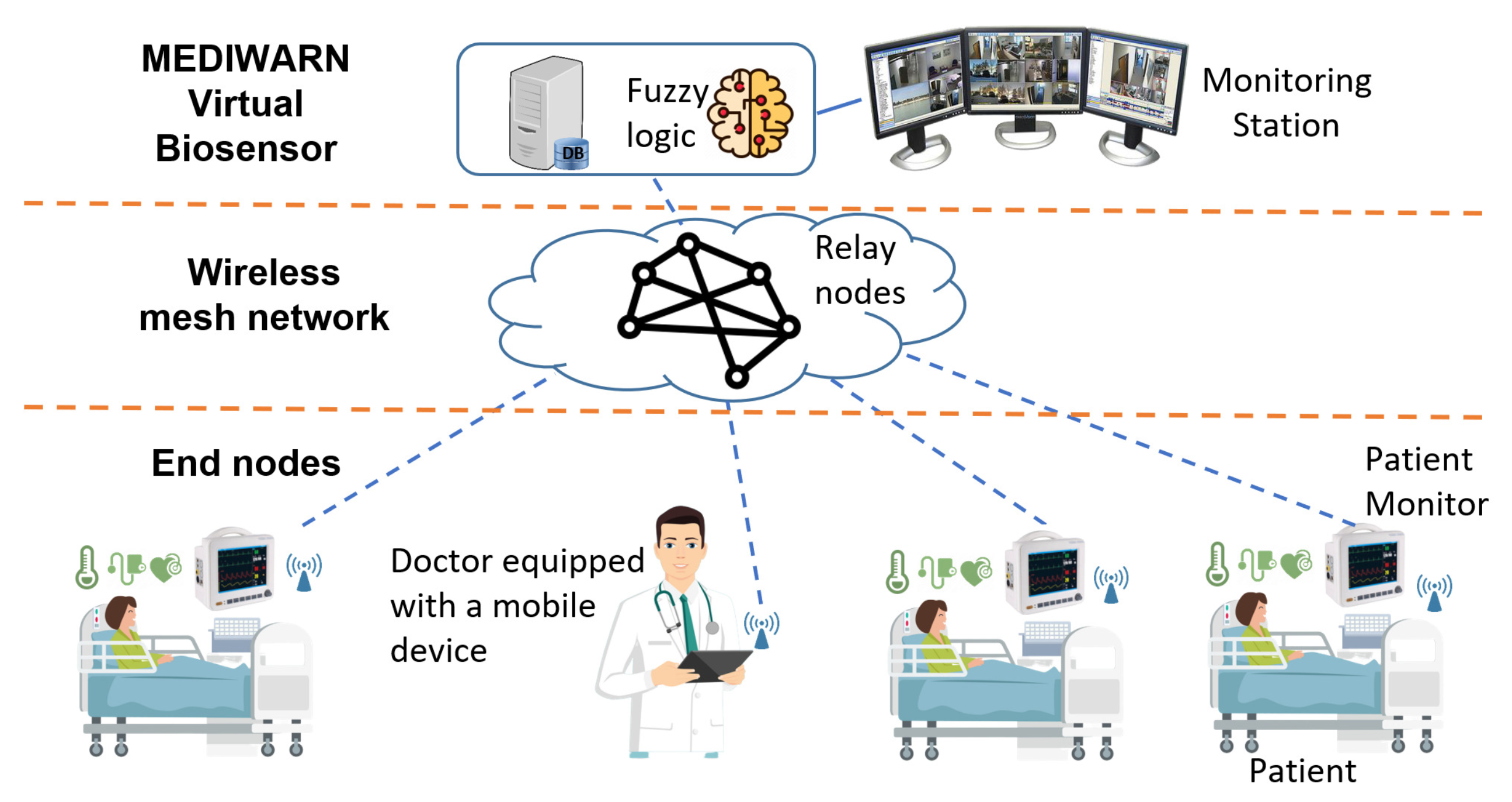
The MEDIWARN system, as shown in Figure 1, includes patients, doctors, sensors, monitors, some wireless nodes (including mobile handheld devices), the MEDIWARN Virtual Biosensor and a monitor station.
The sensors acquire the physiological parameters of the patient. Two kinds of vital parameters are considered, i.e., both waveforms and single values.
The sensory data are collected and shown on a monitor close to the patient. The monitor is equipped with a wireless transceiver and transmits the vital parameters to the MEDIWARN Virtual Biosensor for data processing.
The wireless network consists of a number of wireless nodes, organized in a mesh topology, that act as relay nodes in the data exchange between the monitors and the MEDIWARN Virtual Biosensor.
The MEDIWARN Virtual Biosensor (Figure 2) is the heart of the proposed model and consists of a dedicated server that stores and processes the vital parameters of the patients. Such a server runs four software components:
  • A database that stores all the vital parameters sampled from the patients and the processing results.
  • A data acquisition component that is in charge of the communication with all the monitors, which collects the vital parameters sampled by the monitors and stores them in the database.
  • The fuzzy algorithm, which communicates directly with the database, reads the vital parameters, processes data and stores the results in the database.
  • The web portal, i.e., a web server that maintains the GUI for the workstation and the mobile devices held by the medical staff. The traffic of mobile devices is web traffic with no real-time guarantees.
The medical team can remotely monitor the patients through the mobile devices, which show the patients’ current clinical status. Moreover, the medical staff is promptly informed of any patient’s condition deterioration through an alarm that is sent by the MEDIWARN Virtual Biosensor to the mobile devices. This way, the medical staff members are alerted by an acoustic signal generated by their mobile devices.
The monitoring station shows a detailed view of each patient’s conditions, while the mobile handheld devices (e.g., tablets) of the medical staff provide a summarized view of the patients’ status.
The MEDIWARN communication system involves a wireless network architecture such as the one in Figure 1 for each hospital ward. In the case multiple hospital wards would use the MEDIWARN system, the wireless networks should exchange data through wired technologies (e.g., Ethernet).

4. Research Challenges and Solutions

This section discusses the research challenges that the MEDIWARN communication system poses and the design choices made to address the system requirements.

4.1. Requirements

The wireless network involved in the MEDIWARN system must satisfy several application requirements, which pose the following design challenges.
High data rate. The monitors may need to transmit a significant amount of data within short intervals (e.g., waveforms). For this reason, a wireless technology that support high data rates is required.
Local communications. The patients’ data have to be transferred over a private network that is locally managed within the hospital. This design choice was driven by the explicit request of the medical staff involved in the MEDIWARN project to avoid transmitting sensitive data to remote servers. This choice is beneficial to privacy and it also makes the data availability independent of any network provider.
Reliability and fault-tolerance. The MEDIWARN communication system needs to provide high reliability and availability, as the monitoring must work and the patient’s vital parameters must be delivered to the MEDIWARN Virtual Biosensor even in the case of faults. Consequently, negative conditions, such as interference or faults in one or multiple nodes, shall not make the communication network fail. For these reasons, suitable mechanisms, such as retransmissions and node/path redundancy, are needed. In addition, the host running the MEDIWARN Virtual Biosensor must be fault tolerant, thus hardware and software redundancy have to be introduced.
Mobility. The MEDIWARN system involves handheld devices, i.e., mobile nodes. As a consequence, mechanisms to support node mobility are required.
Multi-hop communication. The target application may demand for large-scale communication network deployments, and therefore the monitors can be multiple hops away from the MEDIWARN Virtual Biosensor. This requires the adoption of a number of relay nodes, i.e., intermediate nodes that receive the messages intended for other nodes and forward them up to their final destination. The number and placement of such relay nodes must be accurately evaluated according to some metrics, such as the coverage range of each node and the number of senders in a specific area. Moreover, a trade-off between the number of relay nodes and the network reliability (node/path redundancy) has to be found. In fact, while a higher number of relay nodes provides multiple paths for each message transmission from a source to the intended destination, and therefore alternative ways to reach the destination even in case of faults (e.g., a node failure), it entails higher costs in terms of network devices and energy consumption.
Routing. In the MEDIWARN network architecture, routing, i.e., the process of selecting one or multiple paths for message forwarding, is a critical issue. In fact, the routing protocol should not introduce a significant overhead, in terms of network workload, to not impair the communication network performance in terms of end-to-end delay. This turned out to be a research question, as explained in the following subsection. The solution here proposed is presented in Section 5.
Real-time. The MEDIWARN system continuously collects and processes data in order to promptly alert the medical staff. Consequently, bounded delivery times must be guaranteed to the messages carrying such data. In particular, the Virtual Biosensor considers the monitor transmission period as a soft deadline on the message delivery time, which can be occasionally exceeded without compromising the proper system operation. However, any data delivered to the receiver with a delay longer than the transmission period are not useful for real-time monitoring, and therefore they are not forwarded to the virtual biosensor. This aspect, combined with the requirements on routing previously mentioned, also poses a research challenge. In the following, the design choices corresponding to the above-mentioned requirements are described in detail.

4.2. Design Solutions

Communication technology. The IEEE 802.11 (WiFi) technology offers high bandwidth and high quality of service [35,36]. Compared to other high-bandwidth wireless technologies, such as cellular networks, WiFi is locally managed and its availability does not depend on any network provider. For these reasons, WiFi is the technology chosen for the MEDIWARN system. In addition, the use of IEEE 802.11-based networks allows to maintain sensitive data within the hospital intranet (instead of sending them through the Internet), thus meeting one of the previously discussed MEDIWARN system requirements.
The IEEE 802.11 standard supports both the infrastructure operating mode and the ad-hoc one, but the requirements of the MEDIWARN systems lead to the use of WiFi in ad-hoc mode, as it offers higher flexibility and higher fault tolerance. Such a choice meets both the high data rate and local communication requirements. In fact, the ad-hoc mode allows each end node to communicate directly with the other end nodes within the same coverage area and supports link redundancy. This way, mesh topologies are supported and the same message can be transmitted over multiple paths. However, WiFi in ad-hoc mode increases the network management complexity.
Redundancy mechanisms. In order to guarantee the message delivery even in case of faults (e.g., intermediate node failures) or corrupted transmissions due to interference or noise, both spatial redundancy and retransmission mechanisms were adopted in the MEDIWARN system. This way the reliability and fault-tolerance requirements are met. Spatial redundancy, allowing for transmissions on multiple paths, increases the probability that the messages will be received correctly. The retransmission mechanism is based on end-to-end acknowledgements (ack), and therefore a missing ack after a message transmission will indicate that something went wrong and will cause the retransmission of the unconfirmed message.
Mesh topology with mobility support. According to the hospital organization, the MEDIWARN system may require a large-scale deployment that includes mobile nodes. As a result, the wireless network needs to manage a dynamic topology [37] and multi-hop communications. For this reason, a mesh topology with a proper number of relay nodes is needed to guarantee a total coverage of the hospital units included in the MEDIWARN system. The number of relay nodes needed in a specific application scenario depends on multiple parameters. Among them, the area to be covered, the devices used and their transmission power, the presence of obstacles, interference and signal attenuation and the reliability level required by the application.
This strategy provides the nodes with mobility support, as the handheld devices can freely move within the area without losing the local wireless connection. The wireless nodes, therefore, dynamically establish all the possible connections between each other to create a mesh topology and support multiple transmission paths for messages from the source to the intended destination.
Routing protocol. The MEDIWARN system includes mobile nodes, i.e., the handheld devices of the medical staff on the move within the hospital unit and the patients’ monitors, which can be relocated according to the hospital unit needs. Consequently, a dynamic routing protocol is considered the best option for MEDIWARN. This way, message forwarding is based on the current network conditions and the routing protocol is able to route around faults, such as node failures or loss of connection between nodes.
Several routing protocols were standardized for ad-hoc wireless networks [38]. Among them, the Ad-hoc On-demand Distance Vector (AODV) and the Dynamic Source Routing (DSR) are reactive protocols that, on demand, select a path from the source to the destination. As discussed in ref. [38], although these approaches entail a low overhead in terms of the workload introduced by the routing message exchange, they increase the network latency.
Since MEDIWARN requires low latency communications, the above mentioned protocols are not suitable solutions, whereas proactive or hybrid routing protocols could be considered. However, both the Destination-Sequenced Distance-Vector Routing (DSDV) and the Temporally Ordered Routing Algorithm (TORA), as discussed in ref. [38], would significantly increase the network workload in the MEDIWARN system.
Another option could be the hybrid routing protocol for wireless mesh routing that is defined in the IEEE amendment 802.11s [39,40]. However, the IEEE 802.11s requires specific hardware/software features that may not be supported by a number of COTS devices.
Due to the limitations in this respect of the state-of-the-art solutions previously mentioned, here, a custom routing protocol is proposed for the MEDIWARN system. The protocol, called the MultiPath Routing Protocol for MEDIWARN (MP-RPM), is described in Section 5 and aims to support reliable transmissions on a dynamic network, while limiting the network overhead due to the control messages. Being totally hardware independent, MP-RPM can be used on any COTS device without any hardware/software modifications (unlike the IEEE 802.11s standard).
Soft real-time communications support. Soft real-time messages have deadlines that are taken into account when routing and forwarding messages, but without strict guarantees, so an occasional deadline miss may happen and it is tolerated. However, the messages carrying, for example, a patient’s physiological parameters, if not delivered on time, will not be used for real-time monitoring and will not be displayed on the screen that shows the patient’s current conditions.
To minimize the number of deadline misses, here, we propose an IEEE 802.11-based mesh network that includes on the relay nodes suitable mechanisms to improve the soft real-time performance of the MEDIWARN system. Each relay node implements a priority queue of outbound messages. When a node receives a message to forward, the message is inserted in the queue. Message priority is assigned according to a configurable criterion, for example, the hop count, i.e., the number of hops that the message has traversed so far. This way, the messages that traverse more links to reach the destination would be favored to compensate for the longest path.
In addition, the custom routing protocol (i.e., the MP-RPM) here proposed allows choosing the best next hop for each message to be forwarded based on a route selection algorithm. In particular, every time a message needs to be forwarded by a relay node, the latter searches its routing table for all the possible routes to the destination. The routes are sorted from best to worst according to a configurable metrics, e.g., the hop distance, so the relay node selects the first path to forward the message. This way, each message follows the best path between the sender and the receiver based on a specific metrics. Note that, as discussed in Section 5.2, the MP-RPM implements multipath routing, and therefore each message can be sent over multiple paths to provide redundancy and increase the protocol reliability. Consequently, each relay node selects the first n _ p a t h paths thanks to the route selection algorithm.
Summarizing, the MEDIWARN system needs a simple, lightweight and configurable routing protocol able to both take the message priority into account to reduce the delay of soft real-time messages and provide path redundancy and mobility support without significantly increasing the network workload and latency. The solution here proposed is described in detail in the following Section.
5. The MultiPath Routing Protocol for MEDIWARN (MP-RPM)

Here, we consider a network made up of three different node types, i.e., end nodes, relay nodes and the sink. The end nodes are unaware of the network routing logic, so they broadcast the data acquired by the sensors without any path (or route) selection. The relay nodes are the core of MP-RPM, as they take care of message forwarding in the network, from the source to the destination. The sink, i.e., the MEDIWARN Virtual Biosensor in Figure 1, is the network collector, i.e., the destination node of all the sensor data sent by the end nodes.
The MP-RPM works over the medium access control (MAC) layer, uses standard IEEE 802.11 frames and the EUI-48 address format. The relay nodes are set to receive all frames in promiscuous mode (regardless of their destination address). Finally, the end nodes and their applications are totally unaware of the network topology and the routing protocol used, i.e., they simply send messages with the sink address as destination. The relay nodes are in charge of forwarding these messages to the sink. This way, as the end nodes do not take part in the routing decision, any node can be supported, regardless of the high-level application that runs on it.
The MP-RPM can be split into two phases, i.e., initialization (init) and data exchange, as described below.

5.1. Init Phase

The network nodes are initially unaware of the network topology, so they do not know the possible paths to forward the messages to their destination. Each node, with the exception of the end nodes, needs to build a routing table (rTable) during the init phase to keep track of the network topology. At the end of the init phase, each node will be able to choose, according to a configurable metrics, the best path to forward the messages to their destination. Each entry of the routing table of the node A contains the following data: the destination node (B) address, the number of hops (n) between A and B and the address of the node to which forward the message in order to reach B through n hops (i.e., the next hop).
Since the network topology can change, the init phase needs to periodically run (with a configurable period, here called u p d _ p e r i o d ). This period is configurable and depends on several aspects, such as the number of mobile nodes and their mobility pattern and the presence of moving obstacles. A lower value of u p d _ p e r i o d offers higher ability to react to network changes. However, as the u p d _ p e r i o d impacts on the overhead introduced by the routing protocol, a trade-off between the overhead introduced by MP-RPM and its reaction rate towards network changes must be determined.
During this phase, the sink and the relay nodes run Algorithm 1.
Both the sink and the relay nodes transmit an init message containing the address of the source node (i.e., the originating node of the init message), the number of hops field ( h o p C n t ) that is initially set to 0 by the source node and then increased every time the init message is forwarded and a sequence number ( s e q N ).
The nodes that transmit the init message wait for other init messages. Each relay node and the sink will run the init algorithm until a timer, called the receive timer ( r c v T i m e r ), expires. The receive timer measures the time interval during which no messages are received. If no init messages are received for r c v T i m e r V a l u e (i.e., a configurable time interval), the init phase ends.
Algorithm 1 Init phase
1:
h o p C n t = 0
2:
s e q N = 0
3:
m s g = m a k e _ i n i t _ m s g ( m y A d d r , h o p C n t , s e q N )
4:
s e n d _ i n i t _ m s g ( b r o a d c a s t , m s g )
5:
while (not rcvTimerExpired()) do
6:
m = r c v _ i n i t _ m s g ( )
7:
i n = r T a b l e . c o n t a i n ( m . s r c A d d r )
8:
if (in) then
9:
   p a t h = r T a b l e . c o n t a i n ( m . s r c A d d r , m . n x t H o p )
10:
end if
11:
if (not i n or ( i n and (not p a t h or not b e s t P a t h ( ) ))) then
12:
   r T a b l e . a d d ( m . s r c A d d r , m . h o p C n t , m . n x t H o p )
13:
else if ( i n and p a t h and not b e s t P a t h ( ) ) then
14:
   r T a b l e . u p d ( m . s r c A d d r , m . h o p C n t , m . n x t H o p )
15:
else
16:
   d i s c a r d ( m )
17:
end if
18:
if (isRelayNode(myAddr)) then
19:
   m . h o p C n t = m . h o p C n t + 1
20:
   f o r w a r d _ i n i t _ m s g ( b r o a d c a s t , m )
21:
end if
22:
end while
During the init phase, upon reception of an init message, both the sink and the relay nodes update their routing table as follows.
  • If the routing table does not contain an entry that specifies a route to the init message source node, then a new entry is added.
  • If the routing table contains an entry that specifies a route to the init message source node, but the next hop is a different node than the one that just forwarded the init message from the same source, then a new entry is added.
  • If the routing table includes an entry with a route to the init message source node and the same next hop, but with a higher number of hops than the one contained in the received init message (i.e., the b e s t P a t h ( ) function returns f a l s e ), then the routing table entry is updated with the new value for the number of hops.
The relay nodes, i.e., the nodes for which the function i s R e l a y N o d e ( ) returns t r u e , forward the init messages received by the other nodes (i.e., both the relay nodes and the sink) according to a controlled flooding mechanism that avoids retransmitting the init messages that have been already forwarded.
The end nodes discard any init message, as they are totally unaware of the network topology and the routing protocol.

5.2. Data Exchange Phase

At the end of the init phase, each node has built its own routing table and the data exchange phase begins.
In this phase, application messages, such as the ones containing the vital signs of a monitored patient, are sent by the end nodes to the sink. Each application message is encapsulated into an Ethernet frame that contains both the source and the destination addresses. The Ethernet frame is then converted into an IEEE 802.11 frame. The relay nodes encapsulate the message in a specific frame format that contains both a sequence number that, in combination with the source address, uniquely identifies the frame in the network and the message type, i.e., routing message or application message. The application frame is then de-encapsulated at the destination, i.e., the sink node.
During the data exchange phase, each end node periodically (with a configurable period) acquires the vital parameters of a patient and broadcasts them. The end nodes do not implement any routing mechanism. In fact, running Algorithm 2 is up to the relay nodes that are in charge of forwarding the messages to the destination.
Algorithm 2 Relay node—data exchange phase
1:
while (true) do
2:
m = r c v _ d a t a _ m s g ( )
3:
f w = c h e c k _ f o r w a r d e d ( m )
4:
if (not f w ) then
5:
   p a t h S e t = r T a b l e . s e a r c h _ p a t h ( m . d s t A d d r )
6:
   s o r t ( p a t h S e t , c r i t e r i o n )
7:
  for (i = 0; i < nPath; i++) do
8:
    m s g _ f o r w a r d ( p a t h S e t . p o p ( ) , m )
9:
  end for
10:
else
11:
   d i s c a r d ( m )
12:
end if
13:
end while
Upon receiving an application message, a relay node checks if such a message has been already forwarded (in such a case, the c h e c k _ f o r w a r d e d ( ) function returns t r u e ). If so, the message is discarded; otherwise, a route selection algorithm is run. In particular, the relay node searches in its routing table for all the possible routes to reach the destination. The routes found are sorted in ascending order according to the number of hops required to reach the destination. Next, the relay node selects the first n _ p a t h paths through which to forward the message. Note that the MP-RPM implements a multipath routing, i.e., each message is sent to multiple paths, to provide redundancy and increase the protocol reliability. Finally, the message is forwarded to the n x t H o p nodes of the selected routing table entries.
Once an application message has reached its destination (i.e., the sink), the latter checks if such a message has been already received. If not, the sink passes it to the application. Note that the acknowledgement is transmitted at the application layer from the sink to the source and it will be forwarded to the source node using the same mechanism previously described in Algorithm 2.
When the relay nodes receive the application messages sent from the end nodes nearby, they know which end nodes can be reached through a single-hop communication. This information is inserted in the routing table, by adding proper entries, and then it is propagated to all the relay nodes through a suitable message. The medical staff handheld devices are supported by the MP-RPM algorithm, as such devices periodically send (with a configurable period) to the sink a request for updates relevant to the conditions of one specific patient or of all the patients. Consequently, the sink sends the latest data collected from the end node(s) relevant to all the patients or to the specific one. The relay nodes will forward these messages to the destination, i.e., the tablet that issued the request.

6. Implementation and Performance Evaluation

Here, a proof-of-concept implementation of the MEDIWARN communication system on COTS devices is presented. The aim is to show the feasibility of the proposed network architecture and to assess its performance.
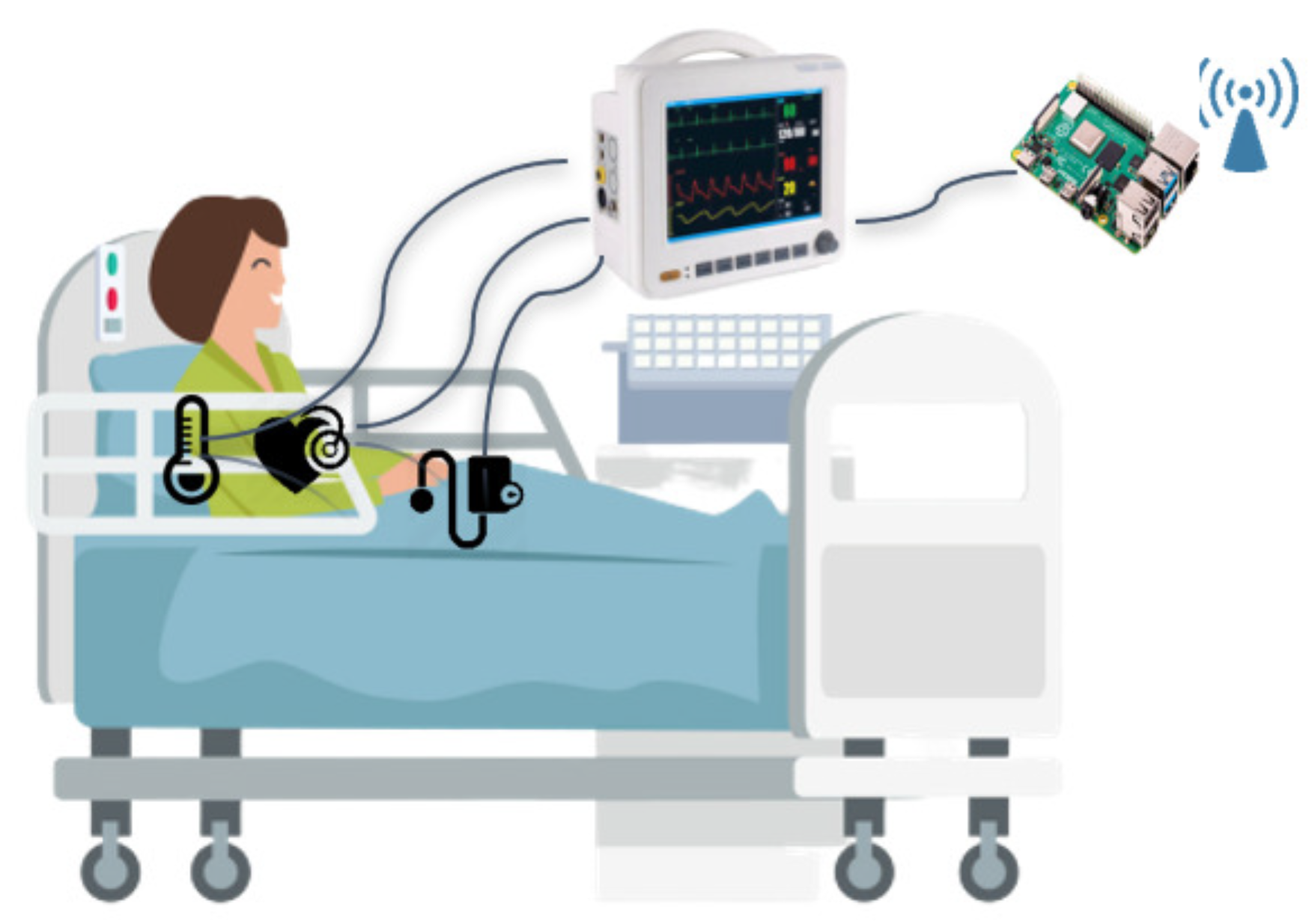
As shown in Figure 3, each end node consists of a number of sensors connected to a Philips IntelliVue MP5 monitor that shows the detected vital parameters and sends them through a Raspberry Pi.
The MP-RPM is implemented on the Raspberry Pis, which act as relay nodes. The implemented version of MP-RPM allows setting a static value of u p d _ p e r i o d . However, an algorithm to dynamically change the u p d _ p e r i o d at runtime can be very helpful in a dynamic context and will be addressed in future work.
The sink, i.e., the MEDIWARN Virtual Biosensor in the architecture shown in Figure 1, consists of a Raspberry Pi that collects sensor data and a server that processes the data.
Since the paper deals with the MEDIWARN network architecture, here, we assess the proposed communication system without addressing the logic implemented by the virtual biosensor.

6.1. Evaluated Scenario

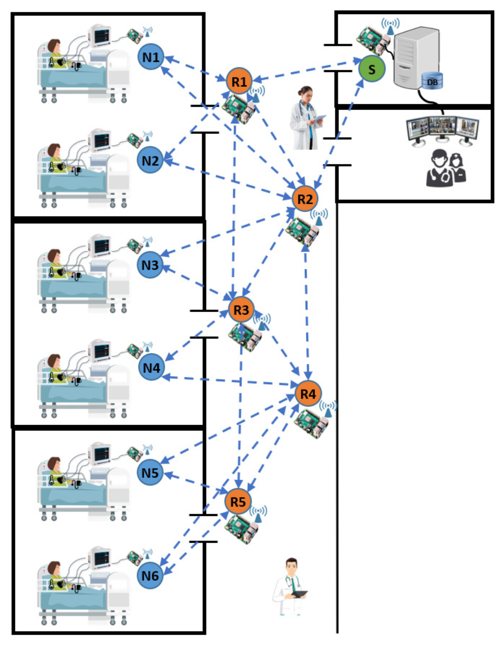
The considered scenario, as shown in Figure 4, consists of three hospital rooms and a corridor. Each room hosts two patients, each one with their own monitor. The patients (each one with a monitor and a Raspberry Pi) represent the end nodes (N1–N6), i.e., the senders, while the MEDIWARN Virtual Biosensor, which is located at the end of the corridor in a dedicated room, is the sink (S), i.e., the receiver. Next to the latter room, there is the monitoring room that hosts the monitoring station. Five relay nodes (R1–R5) are placed in the corridor. The monitors acquire the vital signals of the patients using multiple sensors, as shown in Figure 3, and send them to MEDIWARN Virtual Biosensor through a Raspberry Pi.
The location of the relay nodes is fixed, as shown in Figure 4, to ensure that multiple paths always exist. This way, the messages can be forwarded to the destination even in the case of relay node failures, for fault-tolerance purposes. The relay nodes forward the received messages through the best two paths according to the MP-RPM routing algorithm.
The aim of this assessment is to evaluate the timing and reliability of the communication system when the messages are transmitted through two different paths. No retransmission mechanisms are implemented at the application layer.
Each end node generates one data flow, whose transmission period is set to 1 s. Each message is 60 bytes long. The sampling and sending times of the end nodes are not synchronized with each other. Each relay node implements a priority transmission queue that contains the outbound messages. The priority of messages can be assigned according to a configurable policy. In the considered scenario, to keep it simple, we adopted First-In First-Out (FIFO). The experimental assessment duration was set to 1800 s, i.e., 30 min.

6.2. Analysis of the Experimental Results

This subsection presents the results of the experimental assessment of the MEDIWARN communication system.
The used performance metrics are the Round Trip Time (RTT) and the Packet Loss Ratio (PLR).
The RTT is the time difference between the message sending time at the sender and the reception time of the relevant ack at the same node, measured at the application layer, calculated according to Equation (1):
R T T = A c k A r r i v a l T i m e S e n d T i m e
The PLR, measured at the application layer, is expressed as a percentage of the total number of transmitted messages, according to Equation (2),
P L R = ( n l o s t M s g n t x M s g ) × 100 = ( 1 n r x M s g n t x M s g ) × 100
where n t x M s g , n l o s t M s g and n r x M s g are the number of transmitted, lost and correctly received messages relevant to an end node. Note that a message is considered lost if either the message or the ack is lost.
Table 1 shows the maximum and the average RTT measured for each end node and the corresponding confidence interval calculated at 95%. The RTT gives an estimation of the network timings.
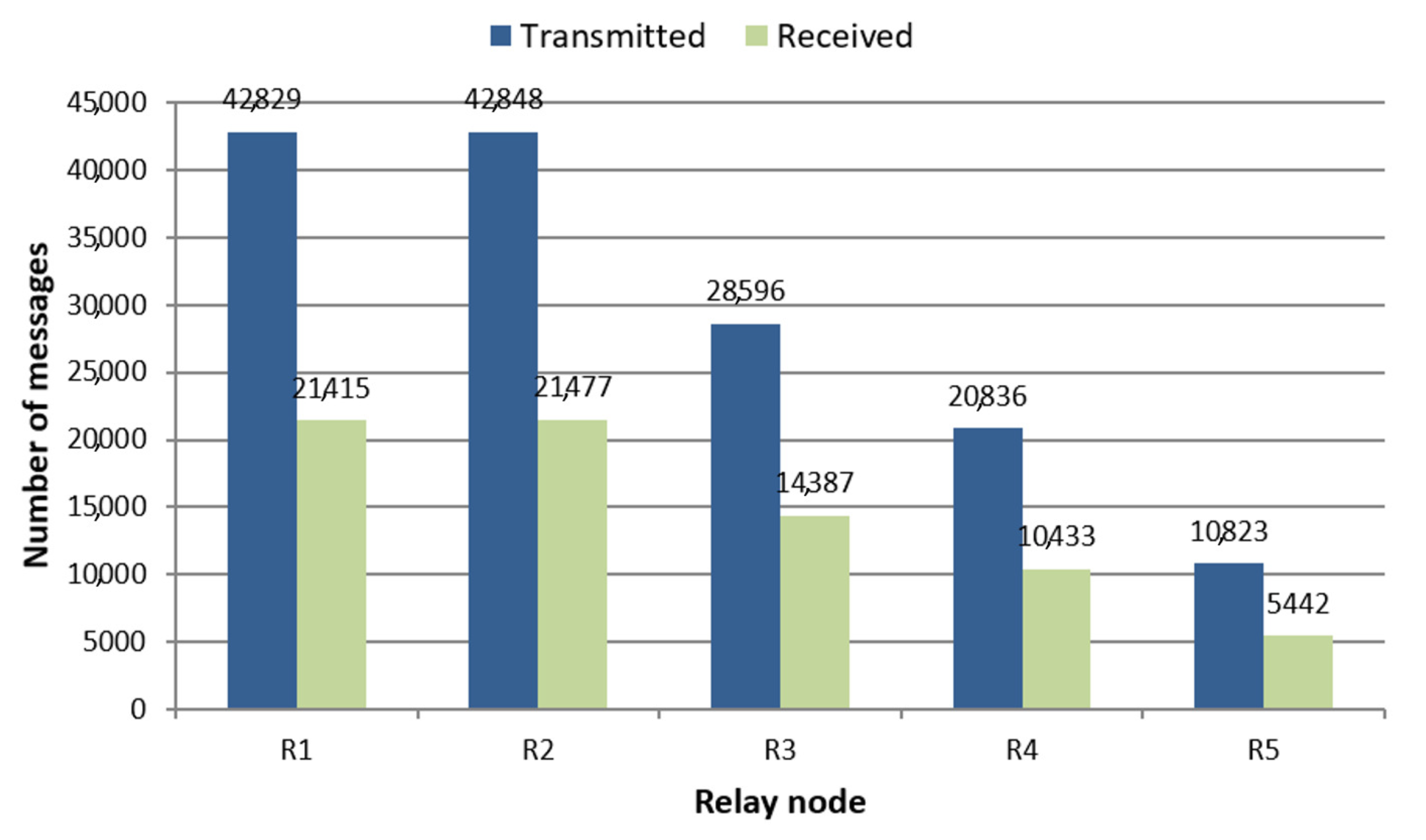
As expected, the highest average RTT values are obtained by the end nodes that are furthest from the receiver, i.e., N5 and N6, as their way to the destination and vice versa traverses the highest number of hops. The average RTT measured at the nodes N3 and N4 is slightly lower than the one at nodes N1 and N2, although the latter are closer to the sink. In fact, despite being closer to the sink in terms of hop distance than N3 and N4, the higher channel load in the coverage area of the N1 and N2 nodes negatively impacts the channel backoff time, and therefore the timing performance of the IEEE 802.11 CSMA/CA MAC layer. As a result, on average the RTT decreases with the number of hops between the sender and the receiver. However, the channel load also affects the RTT, and therefore in the monotone increasing trend that relates the number of hops to the RTT slight variations can be observed. In Figure 5, which shows the number of messages transmitted and received by each relay node during the experimental assessment, it can be seen that the highest channel load is found nearby the relay nodes R1 and R2, while the load significantly decreases with the distance from the sink.
Moreover, the results in Table 1 show that, in the assessed scenario, the maximum RTT is in the order of hundreds of milliseconds, and therefore it stays below the transmission period. As a result, all the messages delivered to their destination will be used for real-time monitoring and displayed on the screen that shows the current patients’ conditions.
Table 2 shows the PLR measured for each end node.
The PLR values obtained are always below 4%. As expected, the hop distance of the nodes from the sink affects the PLR, i.e., the higher the distance, the higher the PLR. However, the low values of the maximum RTT allow retransmitting the messages with a low probability of missing their deadlines. The second factor that affects the PLR is the channel load. For instance, the higher PLR value obtained by the node N2, comparing with that of the node N1, is because N2 is closer to N3 and R2, thus it experiences a higher channel load than N1. The PLR of node N3, compared to that of node N4, mainly depends on its position, as node N3 is closer to node R2 than node N4, and therefore N3 suffers from a higher channel load than node N4. Finally, the nodes N5 and N6 obtained the highest PLR because, in their case, the component that has a greater effect on the PLR is the hop distance from the sink.

7. Simulations

The proposed network architecture was simulated using the OMNeT++ framework. The simulation model is based on the INET libraries, while the application scenario and the network layer models were implemented from scratch based on the MEDIWARN architecture. The scenario here addressed is the one presented for the experimental assessment described in Section 6.1 and shown in Figure 4. To quantify the impact on the delays experienced by the messages transmitted by the monitor when mobile nodes are active, simulations were also performed with two additional mobile nodes on the move between the routers. Such mobile nodes transmit/receive web traffic to the MEDIWARN virtual biosensor at exponentially distributed random intervals with a mean of 10 s.
The assessed metrics are the maximum and average RTT and the PLR, calculated as in Equations (1) and (2), respectively.
The simulation parameters are shown in Table 3. Each simulation was repeated eight times varying the seed for random number generators.
The configured channel model was the log-normal shadowing. The channel model parameters were taken from the work in [41], where the channel was modeled based on experimental measures carried out in a hospital.
The RTT simulation results are shown in Table 4. The average RTT was obtained from 8000 samples and the values are shown with the confidence interval calculated at 95%.
In the case with no mobile nodes, the maximum RTT values are always lower than 300 ms. Only a few of samples obtained an RTT higher than 100 ms and this was experienced by the three nodes at the highest hop-distance from the sink (i.e., N4–N6). Note that such values are of the same order of magnitude as the experimental results. Conversely, the average RTT increases with the hop-distance from the sink. In this case, the simulative results differ from the experimental results by few milliseconds (no more than 10 ms). Such a difference is due to the packet processing time, which is not considered in the simulations. In the case with mobile nodes, the maximum RTT values are very similar to the case without mobile nodes for the nodes that are closer to the sink, i.e., N1–N4. Conversely, the maximum RTT increases to 385 ms and 471 ms for N5 and N6, respectively, which is a very low increase. The average RTT values obtained in the case with mobile nodes are very close to the ones obtained in the case without mobile nodes, thus demonstrating that in the MEDIWARN system scenario mobile nodes do not significantly affect the network performance.
As far as the PLR is concerned, in all the simulations all the transmitted packets were successfully delivered to the destination, despite a harsh channel was configured. Thanks to the redundant paths, the obtained PLR was zero for all the end nodes.
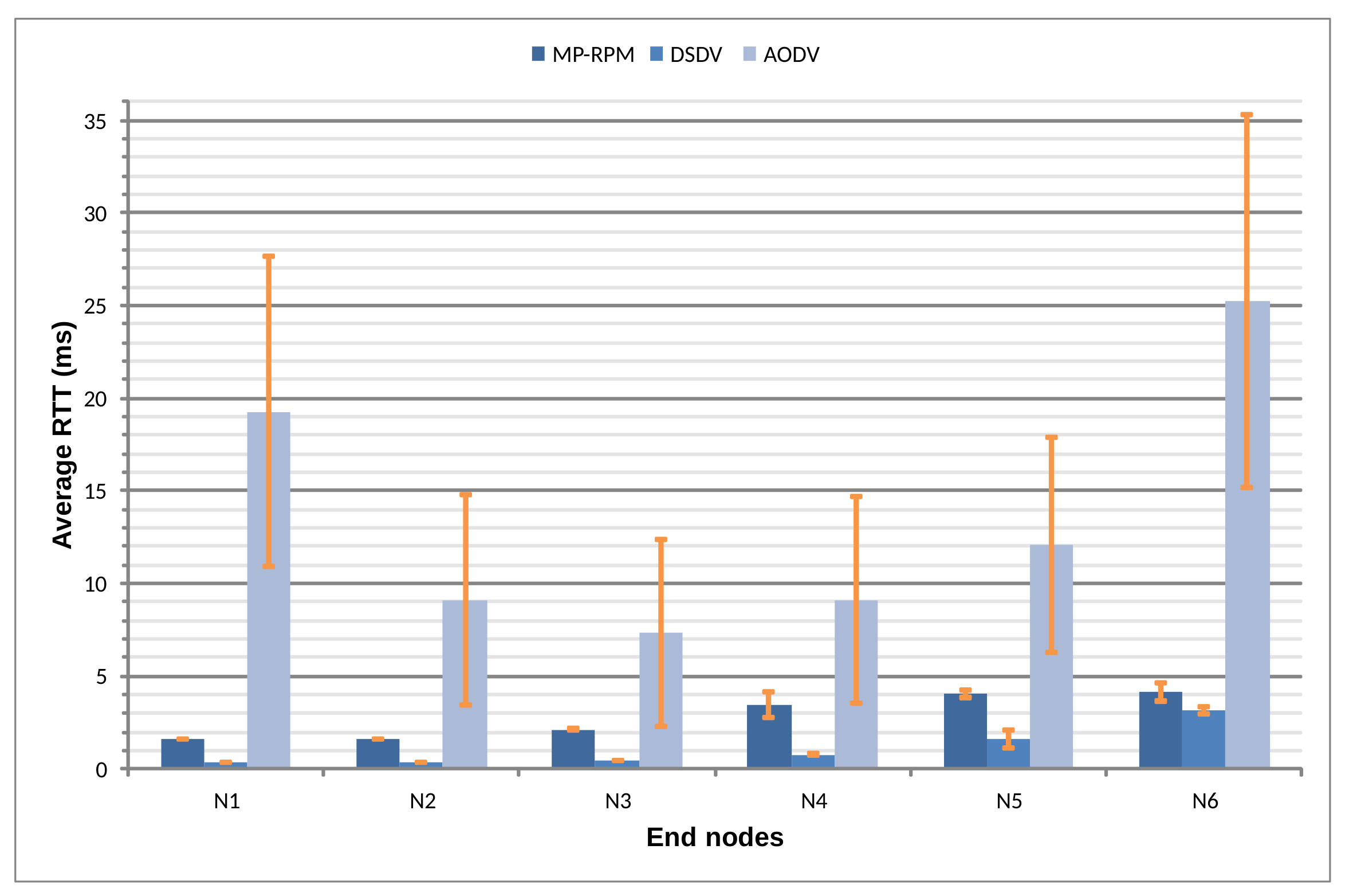
Moreover, to highlight the impact of the routing protocol on the MEDIWARN network performance, we address a comparative assessment of the average RTT and PLR obtained by the MEDIWARN communication system using three different routing protocols, i.e., the MP-RPM presented here, the AODV [11] (an on-demand protocol) and the DSDV [12] (a proactive protocol). The last two protocols are implemented in the INET library. The simulation parameters and the scenario are the same used in the first simulation. The results are shown in Figure 6 and Table 5, respectively.
The results in Figure 6 show that the MP-RPM obtained comparable RTT values than the DSDV although the transmissions, in our approach, are doubled (i.e., repeated over two different paths). In fact, the PLR results (presented in Table 5) show that the PLR values obtained with the DSDV and the AODV are significantly higher than those obtained with the MP-RPM protocol. The AODV protocol obtained significantly higher RTT values (tens of milliseconds), and this is because with AODV the routing path has to be discovered on-demand before starting data transmission, thus increasing the data packet delay.
The PLR results also show that, for this kind of application, proactive protocols perform better than reactive ones. Finally, thanks to the redundant routing path, the MP-RPM outperforms the other two protocols in terms of PLR.

8. Conclusions

This paper discusses the MEDIWARN communication system and a simple, lightweight and configurable routing protocol specifically designed for the needs of the MEDIWARN system. The MEDIWARN communication system provides mobility support and high reliability, through path redundancy and message replication, thanks to the use of relay nodes and the dynamic routing policies of the MP-RPM.
Simulation and experimental results in the assessed scenario demonstrate that the maximum RTT values are always in the order of hundreds of milliseconds, thus fulfilling the requirements of the MEDIWARN system, and that, thanks to the multipath support, the PLR values measured during the experimental assessment were always below 4%. Such values are due to the noisy environment in which the experimental assessment was performed. In fact, simulating the same scenario using the log-normal shadowing channel model, with the parameters obtained from experimental measures in hospitals, zero packet loss was obtained.
One of the limitations of the proposed system is that some relay nodes may eventually become overloaded, when they have to relay a high number of transmissions. As the communication system and the routing protocol were designed to be easily extended with new functionalities, to solve this issue, future works will deal with enhancing the MEDIWARN communication system by introducing load balancing techniques [42] in the MP-RPM. In addition, an extensive performance evaluation of the MEDIWARN communication system will be carried out in scenarios with a higher number of rooms and more patients per room, so that a larger deployment of the MEDIWARN communication system will be assessed. Finally, a comparative performance evaluation of several message priority assignment policies will be performed, with the aim to further reduce the delays of the messages transmitted by the nodes that are a large number of hops away from the MEDIWARN Virtual Biosensor.

Author Contributions

Conceptualization, L.L., L.L.B., G.P. and O.R.; methodology, L.L., L.L.B. and G.P.; software, L.L. and O.R.; validation, L.L.; investigation, L.L., L.L.B. and G.P.; writing—original draft preparation, L.L.; writing—review and editing, L.L.B. and G.P.; supervision, L.L.B.; and funding acquisition, L.L.B. All authors have read and agreed to the published version of the manuscript.

Funding

This research was funded by the INTERREG V-A Italy-Malta Programme 2014–2020, through the “MEDIWARN—Virtual Biosensor for Medical Warning Precursors” European Project (CUP E69F18000000005).

Data Availability Statement

The data underlying this article will be shared on reasonable request from the corresponding author.

Conflicts of Interest

The authors declare no conflict of interest. The funders had no role in the design of the study; in the collection, analyses, or interpretation of data; in the writing of the manuscript, or in the decision to publish the results.

References

  1. Dias, D.; Paulo Silva Cunha, J. Wearable Health Devices—Vital Sign Monitoring, Systems and Technologies. Sensors 2018, 18, 2414. [Google Scholar] [CrossRef] [Green Version]
  2. Mok, W.; Wang, W.; Liaw, S. Vital signs monitoring to detect patient deterioration: An integrative literature review. Int. J. Nurs. Pract. 2015, 21 (Suppl. 2), 91–98. [Google Scholar] [CrossRef]
  3. National Academies of Sciences, Engineering, and Medicine. Improving Diagnosis in Health Care; National Academies Press: Washington, DC, USA, 2015; pp. 31–52. [Google Scholar]
  4. Olla, P.; Tan, J. Mobile Health Solutions for Biomedical Applications; Medical Information Science Reference: New York, NY, USA, 2009; pp. 92–94. [Google Scholar]
  5. Paradiso, R.; Loriga, G.; Taccini, N. Wearable system for vital signs monitoring. Stud. Health Technol. Inform. 2004, 108, 253–259. [Google Scholar]
  6. Khan, Y.; Ostfeld, A.; Lochner, C.; Pierre, A.; Arias, A. Monitoring of Vital Signs with Flexible and Wearable Medical Devices. Adv. Mater. 2016, 28. [Google Scholar] [CrossRef] [PubMed]
  7. Baig, M.; GholamHosseini, H.; Moqeem, A.A.; Mirza, F.; Lindén, M. A Systematic Review of Wearable Patient Monitoring Systems—Current Challenges and Opportunities for Clinical Adoption. J. Med. Syst. 2017, 41, 115. [Google Scholar] [CrossRef]
  8. Baglio, S.; Cammarata, A.; Cortis, P.; Lo Bello, L.; Maddio, P.D.; Nicosia, S.; Patti, G.; Sciberras, S.; Scicluna, J.; Scuderi, V.; et al. Virtual biosensors for the estimation of medical precursors. In Proceedings of the 2019 IEEE International Symposium on Measurements Networking (M&N), Catania, Italy, 8–10 July 2019; pp. 1–4. [Google Scholar] [CrossRef]
  9. Bonnici, T.; Gerry, S.; Wong, D.; Knight, J.; Watkinson, P. Evaluation of the effects of implementing an electronic early warning score system: Protocol for a stepped wedge study. BMC Med. Inform. Decis. Mak. 2015, 16, 19. [Google Scholar] [CrossRef] [PubMed] [Green Version]
  10. Leonardi, L.; Lo Bello, L.; Patti, G. A Wireless Network Architecture for Monitoring of Hospitalized Patients. In Proceedings of the ETFA 2020—25th Annual Conference on Emerging Technologies and Factory Automation, Vienna, Austria, 8–11 September 2020. [Google Scholar] [CrossRef]
  11. Perkins, C.; Royer, E. Ad-hoc on-demand distance vector routing. In Proceedings of the WMCSA’99 Second IEEE Workshop on Mobile Computing Systems and Applications, New Orleans, LA, USA, 25–26 February 1999; pp. 90–100. [Google Scholar]
  12. Perkins, C.; Bhagwat, P. Highly Dynamic Destination-Sequenced Distance-Vector Routing (DSDV) for Mobile Computers. In Proceedings of the Conference on Communications Architectures, Protocols and Applications (SIGCOMM ’94), London, UK, 31 August–2 September 1994; pp. 234–244. [Google Scholar]
  13. Fakhrulddin, S.S.; Gharghan, S.K. An Autonomous Wireless Health Monitoring System Based on Heartbeat and Accelerometer Sensors. J. Sens. Actuator Netw. 2019, 8, 39. [Google Scholar] [CrossRef] [Green Version]
  14. Iannizzotto, G.; Nucita, A.; Fabio, R.A.; Caprì, T.; Lo Bello, L. Remote Eye-Tracking for Cognitive Telerehabilitation and Interactive School Tasks in Times of COVID-19. Information 2020, 11, 296. [Google Scholar] [CrossRef]
  15. Memedi, M.; Tshering, G.; Fogelberg, M.; Jusufi, I.; Kolkowska, E.; Klein, G. An Interface for IoT: Feeding Back Health-Related Data to Parkinson’s Disease Patients. J. Sens. Actuator Netw. 2018, 7, 14. [Google Scholar] [CrossRef] [Green Version]
  16. Ali, F.; El-Sappagh, S.; Islam, S.R.; Kwak, D.; Ali, A.; Imran, M.; Kwak, K.S. A smart healthcare monitoring system for heart disease prediction based on ensemble deep learning and feature fusion. Inf. Fusion 2020, 63, 208–222. [Google Scholar] [CrossRef]
  17. Ali, F.; El-Sappagh, S.; Islam, S.; Ali, A.; Attique, M.; Imran, M.; Kwak, K.S. An intelligent healthcare monitoring framework using wearable sensors and social networking data. Future Gener. Comput. Syst. 2021, 114, 23–43. [Google Scholar] [CrossRef]
  18. Giannakas, F.; Troussas, C.; Voyiatzis, I.; Sgouropoulou, C. A deep learning classification framework for early prediction of team-based academic performance. Appl. Soft Comput. 2021, 106, 107355. [Google Scholar] [CrossRef]
  19. Mdhaffar, A.; Chaari, T.; Larbi, K.; Jmaiel, M.; Freisleben, B. IoT-based health monitoring via LoRaWAN. In Proceedings of the IEEE EUROCON 2017—17th International Conference on Smart Technologies, Ohrid, Macedonia, 6–8 July 2017; pp. 519–524. [Google Scholar]
  20. Leonardi, L.; Lo Bello, L.; Battaglia, F.; Patti, G. Comparative Assessment of the LoRaWAN Medium Access Control Protocols for IoT: Does Listen before Talk Perform Better than ALOHA? Electronics 2020, 9, 553. [Google Scholar] [CrossRef] [Green Version]
  21. Leonardi, L.; Battaglia, F.; Lo Bello, L. RT-LoRa: A Medium Access Strategy to support Real-time flows over LoRa-based networks for Industrial IoT applications. IEEE Internet Things J. 2019, 10812–10823. [Google Scholar] [CrossRef]
  22. Klimiashvili, G.; Tapparello, C.; Heinzelman, W. LoRa vs. WiFi Ad Hoc: A Performance Analysis and Comparison. In Proceedings of the 2020 International Conference on Computing, Networking and Communications (ICNC), Big Island, HI, USA, 17–20 February 2020; pp. 654–660. [Google Scholar]
  23. Leonardi, L.; Battaglia, F.; Patti, G.; Lo Bello, L. Industrial LoRa: A Novel Medium Access Strategy for LoRa in Industry 4.0 Applications. In Proceedings of the IECON 2018—44th Annual Conference of the IEEE Industrial Electronics Society, Washington, DC, USA, 21–23 October 2018; pp. 4141–4146. [Google Scholar] [CrossRef]
  24. Manoharan, A.M.; Rathinasabapathy, V. Secured Communication for Remote Bio-Medical Monitoring System Using LoRa. Sens. Lett. 2019, 17, 888–897. [Google Scholar] [CrossRef]
  25. Pereira, C.; Mesquita, J.; Guimarães, D.; Santos, F.; Almeida, L.; Aguiar, A. Open IoT Architecture for Continuous Patient Monitoring in Emergency Wards. Electronics 2019, 8, 1074. [Google Scholar] [CrossRef] [Green Version]
  26. Kumar, R.; Rajasekaran, M.P. An IoT based patient monitoring system using raspberry Pi. In Proceedings of the 2016 International Conference on Computing Technologies and Intelligent Data Engineering (ICCTIDE’16), Kovilpatti, India, 7–9 January 2016; pp. 1–4. [Google Scholar] [CrossRef]
  27. Leonardi, L.; Ashjaei, M.; Fotouhi, H.; Lo Bello, L. A Proposal Towards Software-Defined Management of Heterogeneous Virtualized Industrial Networks. In Proceedings of the IEEE 17th International Conference on Industrial Informatics (INDIN 2019), Helsinki, Finland, 22–25 July 2019. [Google Scholar] [CrossRef]
  28. Varadharajan, V.; Tupakula, U.; Karmakar, K. Secure Monitoring of Patients With Wandering Behavior in Hospital Environments. IEEE Access 2018, 6, 11523–11533. [Google Scholar] [CrossRef]
  29. Leonardi, L.; Lo Bello, L.; Aglianò, S. Priority-Based Bandwidth Management in Virtualized Software-Defined Networks. Electronics 2020, 9, 1009. [Google Scholar] [CrossRef]
  30. Khayat, M.; Barka, E.; Sallabi, F. SDN_Based Secure Healthcare Monitoring System (SDN-SHMS). In Proceedings of the 2019 28th International Conference on Computer Communication and Networks (ICCCN), Valencia, Spain, 29 July–1 August 2019; pp. 1–7. [Google Scholar]
  31. Kou, J. Intelligent Sensing System of Human Physiological Detection based on Biosensor and WSN—A Review. In Proceedings of the 2020 International Conference on Inventive Computation Technologies (ICICT), Coimbatore, India, 26–28 February 2020; pp. 647–650. [Google Scholar]
  32. Polu, S.K.; Polu, S. IoMT based smart health care monitoring system. Int. J. Innov. Res. Sci. Technol. (IJIRST) 2019, 5, 58–64. [Google Scholar]
  33. Joseph, S.; Francis, N.; John, A.; Farha, B.; Baby, A. Intravenous Drip Monitoring System for Smart Hospital Using IoT. In Proceedings of the 2019 2nd International Conference on Intelligent Computing, Instrumentation and Control Technologies (ICICICT), Kannur, India, 5–6 July 2019; pp. 835–839. [Google Scholar]
  34. Reis, A.; Coutinho, F.; Ferreira, J.; Tonelo, C.; Ferreira, L.; Quintas, J. Monitoring System for Emergency Service in a Hospital Environment. In Proceedings of the 2019 IEEE 6th Portuguese Meeting on Bioengineering (ENBENG), Lisbon, Portugal, 22–23 February 2019; pp. 1–4. [Google Scholar]
  35. Deng, D.; Lien, S.; Lee, J.; Chen, K. On Quality-of-Service Provisioning in IEEE 802.11ax WLANs. IEEE Access 2016, 4, 6086–6104. [Google Scholar] [CrossRef]
  36. Bayrakdar, M.E. Priority based health data monitoring with IEEE 802.11 af technology in wireless medical sensor networks. Med. Biol. Eng. Comput. 2019, 57, 2757–2769. [Google Scholar] [CrossRef] [PubMed]
  37. Toscano, E.; Lo Bello, L. A topology management protocol with bounded delay for Wireless Sensor Networks. In Proceedings of the 2008 IEEE International Conference on Emerging Technologies and Factory Automation, Hamburg, Germany, 15–18 September 2008; pp. 942–951. [Google Scholar] [CrossRef]
  38. Sharma, A.; Kumar, R. Performance comparison and detailed study of AODV, DSDV, DSR, TORA and OLSR routing protocols in ad hoc networks. In Proceedings of the 2016 Fourth International Conference on Parallel, Distributed and Grid Computing (PDGC), Waknaghat, India, 22–24 December 2016; pp. 732–736. [Google Scholar] [CrossRef]
  39. IEEE Standard for Information Technology–Telecommunications and Information Exchange between Systems–Local and Metropolitan Area Networks–Specific Requirements Part 11: Wireless LAN Medium Access Control (MAC) and Physical Layer (PHY) Specifications Amendment 10: Mesh Networking. IEEE Std 802.11s-2011 (Amendment to IEEE Std 802.11-2007); IEEE: Piscataway, NJ, USA, 2011; pp. 1–372. [CrossRef]
  40. Hiertz, G.R.; Denteneer, D.; Max, S.; Taori, R.; Cardona, J.; Berlemann, L.; Walke, B. IEEE 802.11 s: The WLAN mesh standard. IEEE Wirel. Commun. 2010, 17, 104–111. [Google Scholar] [CrossRef]
  41. Lee, P.R.S.; Bui, V.P. Hybrid simulation technique for characterizing wireless channel in medical environments. Prog. Electromagn. Res. 2013, 135, 17–35. [Google Scholar] [CrossRef] [Green Version]
  42. Collotta, M.; Lo Bello, L.; Toscano, E.; Mirabella, O. Dynamic load balancing techniques for flexible wireless industrial networks. In Proceedings of the IECON 2010—36th Annual Conference on IEEE Industrial Electronics Society, Glendale, AZ, USA, 7–10 November 2010; pp. 1329–1334. [Google Scholar]
Figure 1. The MEDIWARN logical network architecture and the system components.
Jsan 10 00044 g001
Figure 2. The MEDIWARN Virtual Biosensor software architecture.
Jsan 10 00044 g002
Figure 3. The components of an end node of the MEDIWARN system.
Jsan 10 00044 g003
Figure 4. The scenario considered for the experimental assessment.
Jsan 10 00044 g004
Figure 5. The workload measured by each relay node in the considered scenario during the experimental assessment.
Jsan 10 00044 g005
Figure 6. Comparative average RTT among multiple routing algorithms.
Jsan 10 00044 g006
Table 1. Maximum and average RTT values measured by each end node during the experimental assessment.
End NodeMax RTT (ms)Avg RTT (ms)
N1200.3410.04 ± 0.38
N2214.4010.38 ± 0.42
N3151.327.33 ± 0.31
N4196.948.03 ± 0.32
N5157.5111.19 ± 0.57
N6220.1911.46 ± 0.56
Table 2. PLR for each end node.
End NodeN1N2N3N4N5N6
PLR (%)0.331.000.890.832.613.89
Table 3. Simulation parameters.
ParameterValue
Radio and MAC ProtocolIEEE 802.11n (2.4 GHz)
Payload Size60 bytes
Transmission Period1 s
Seeds0–7 (repeated 8 times)
Channel ModelLog-Normal Shadowing
Ch. model Path-loss exponent ( α )4.5
Ch. model Standard deviation ( σ )5.5
Table 4. Maximum and average RTT simulation values for each end node.
Without Mobile NodesWith Mobile Nodes
End NodeMax RTT (ms)Avg RTT (ms)Max RTT (ms)Avg RTT (ms)
N17.161.65 ± 0.017.161.65 ± 0.01
N24.591.64 ± 0.016.811.66 ± 0.01
N35.262.25 ± 0.016.682.34 ± 0.01
N4377.683.42 ± 0.18382.123.21 ± 0.03
N5263.214.05 ± 0.06385.174.21 ± 0.23
N6292.514.14 ± 0.12471.714.16 ± 0.23
Table 5. Packet Loss Ratio simulation results for each end node.
End NodeAODVDSDVMP-RPM
N124.55% ± 2.80%0.78% ± 0.60%0%
N225.33% ± 3.54%1.65% ± 0.87%0%
N326.77% ± 3.75%5.87% ± 0.91%0%
N427.80% ± 2.96%17.93% ± 1.31%0%
N533.97% ± 5.75%38.36% ± 1.99%0%
N647.38% ± 1.75%57.57% ± 1.96%0%
Publisher’s Note: MDPI stays neutral with regard to jurisdictional claims in published maps and institutional affiliations.