2.1. Spatial Layout of Intelligent Picking Robot with Double Manipulator
The AUBO-i5 manipulator (AUBO, Beijing, China) robotics technology Co., Ltd., Beijing, China, repetitive positioning accuracy: ±0.02 mm) [
25,
26,
27,
28,
29] exhibits superior positioning accuracy and manipulation capabilities. Its exceptional motion control fidelity and adaptable six-degrees-of-freedom joint architecture facilitate accommodation of harvesting tasks across diverse elevations and orientations. The workspace of a dual-arm robot is formed by overlapping and combining two hemispherical workspaces with a radius of 886.5 mm. Payloads of 5 kg can be stably supported by this manipulator, sufficiently accommodating grasping requirements for various apple cultivars. Integrated safety systems—including impact sensing, joint torque surveillance, and instant halt functionality—effectively mitigate risks of damage to personnel or orchard assets, thereby satisfying collaborative operation standards. Employing modular architecture, the platform enables rapid component interchange and end-effector substitution, permitting adaptation to diverse harvesting implements (e.g., compliant grippers, vacuum-based adhesion units, and specialized harvesting end-effectors). Consequently, this research designated the AUBO-i5 as the foundational platform for constructing the dual-arm harvesting system.
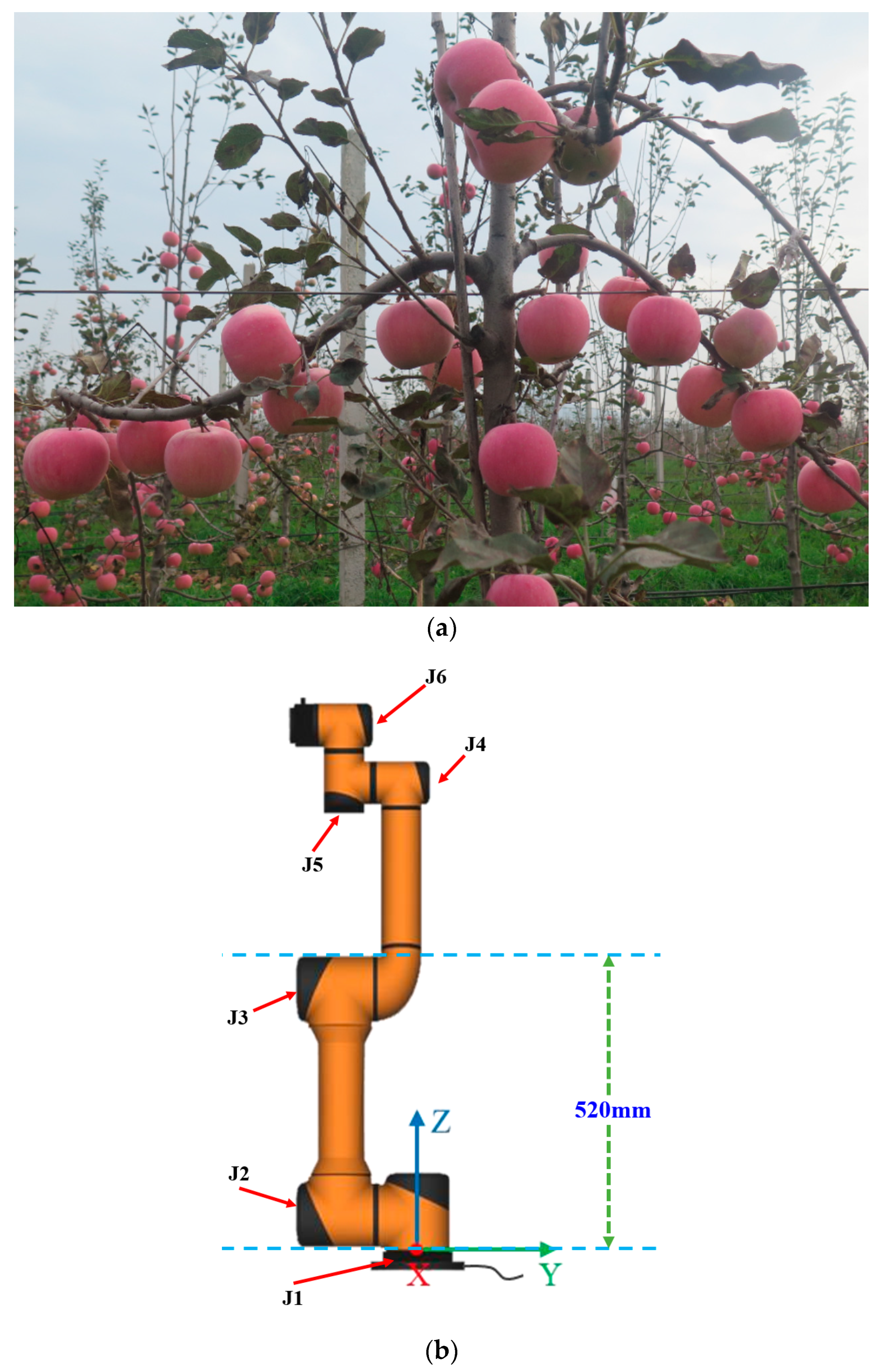
Figure 1 depicts spindle-structured apple trees alongside critical AUBO-i5 dimensional parameters.
The base origins for left and right manipulators are designated as O1 and O2, respectively, with O representing the central reference point. Segments OO1 and OO2 measure 550 mm, providing sufficient clearance for terminal tooling integration. Power interfaces for both manipulators are oriented externally relative to the diagrammatic plane.
In the illustrated configuration, the left manipulator joints 2 and 3 were positioned at 90° rotational displacement, while the corresponding right manipulator joints were set to −90° orientation. Remaining joints maintained neutral (0°) alignment. Mechanical components J
2–J
4 with associated linkages are depicted in
Figure 2.
Operational responsibilities were allocated such that left-sector harvesting targets were assigned to the left manipulator, while right-sector targets were managed by its counterpart. Visual-servo-constrained harvesting ensured collision-free terminal effector operation. Per AUBO-i5 specifications, the 1210 mm separation between base peripheries (2 × 605 mm) exceeds the cumulative linkage dimension for J
2–J
3 segments (1040 mm,
Figure 2), thereby preventing mechanical interference between adjacent J
3 assemblies.
Consequently, despite workspace overlap, visually constrained zone harvesting guarantees collision-free coordination.
For enhanced spatial analysis of the dual-manipulator arrangement, computational modeling was performed using Python (Version 3.7.10) to generate the overlapping workspace schematic (
Figure 3). This representation comprises two partially superimposed hemispherical operational envelopes (radius: 886.5 mm), with O
1 and O
2 indicating base centroids.
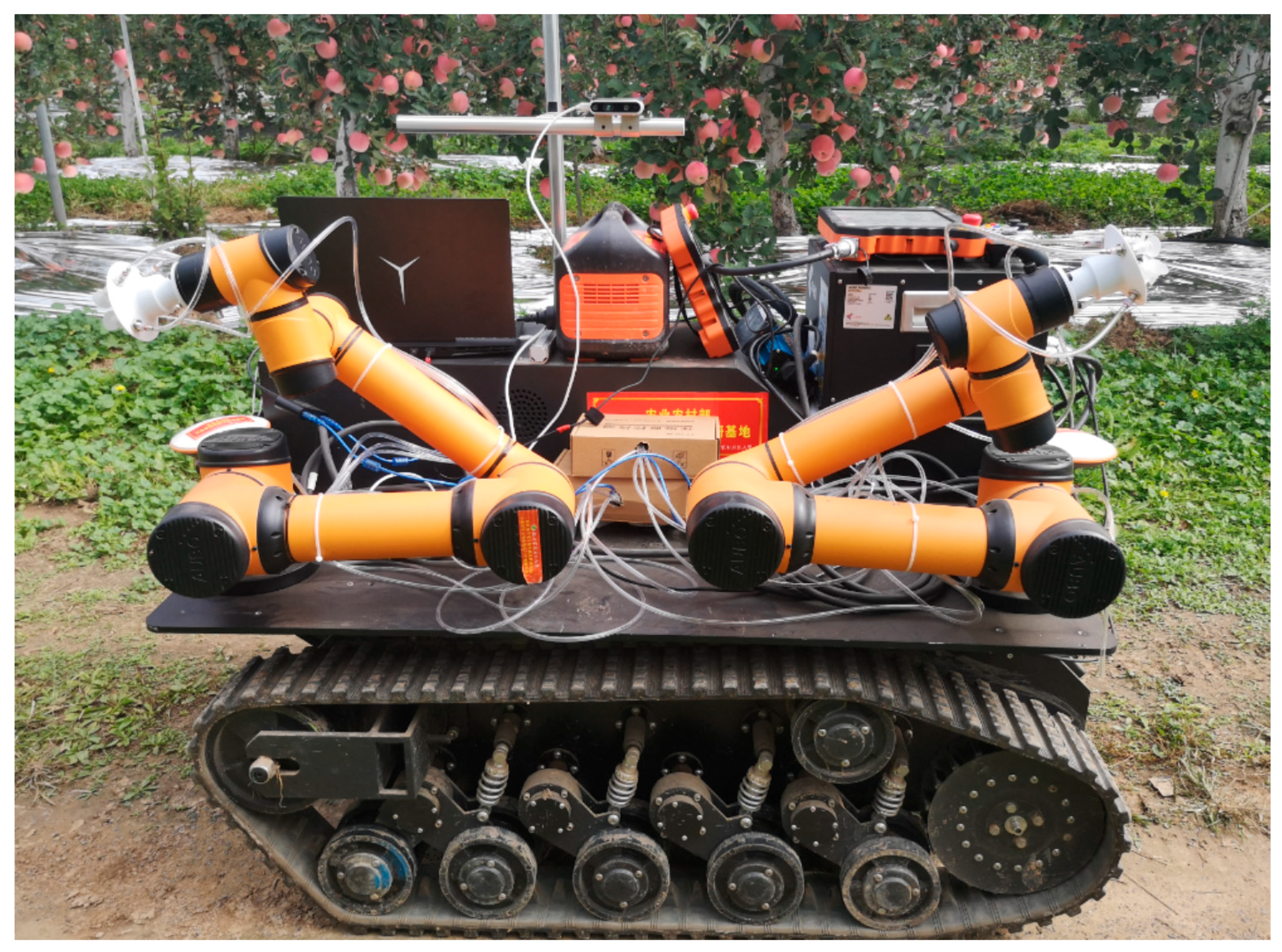
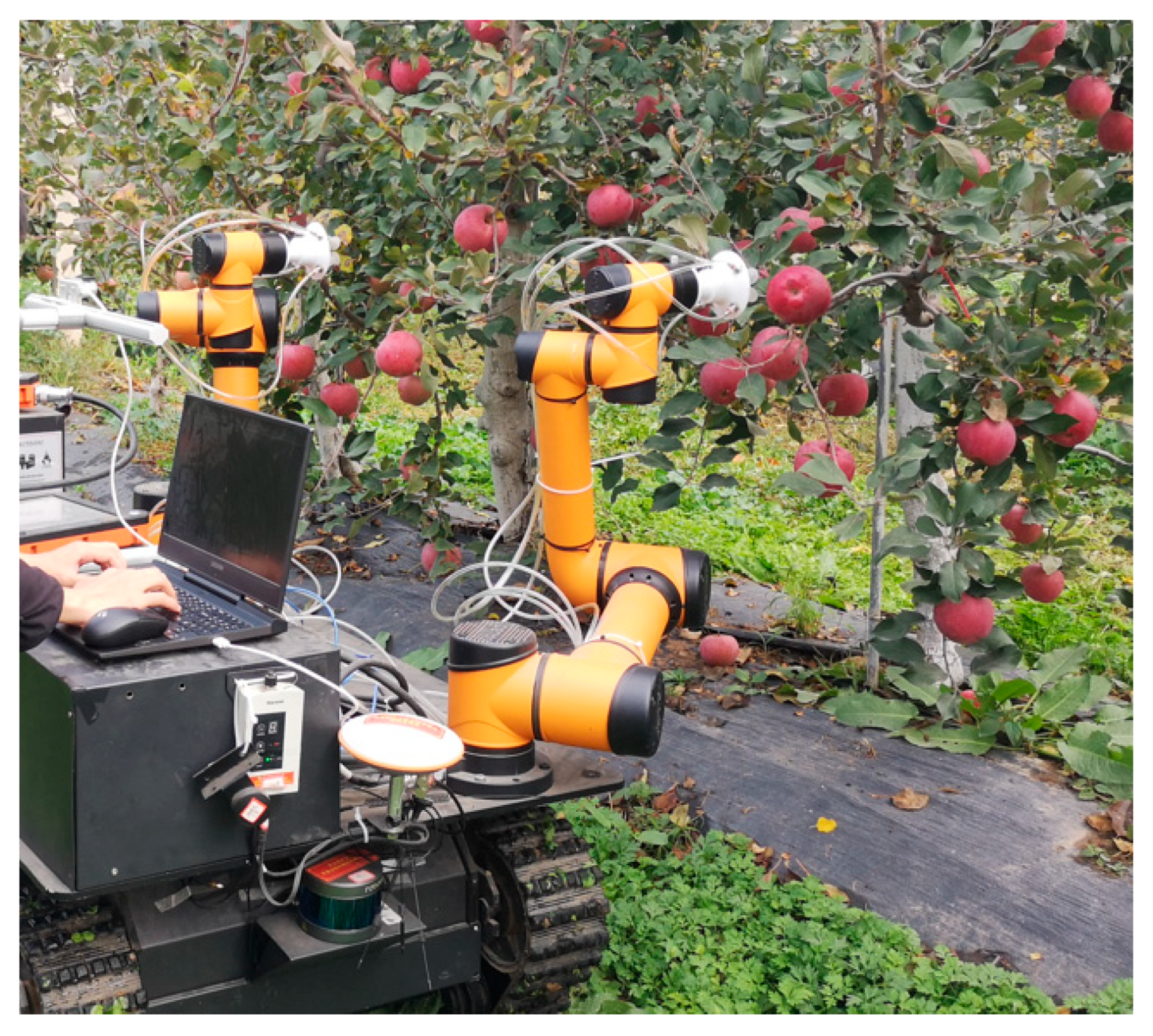
The physical drawing of the double manipulator built on the robot chassis based on this layout is shown in
Figure 4. Dual robotic manipulators are incorporated: specifically, two AUBO-i5 lightweight collaborative arms possessing six degrees of freedom. A modular joint architecture is employed by the AUBO robotic arm, featuring a developer-centric operating system. Tailored robotic control systems designed for particular operational needs can be created by users, utilizing the application programming interfaces supplied by the AUBO framework. Furthermore, a dedicated programmable operator interface is integrated with the AUBO manipulator. Real-time operational data concerning the robot can be monitored through this interface, and diverse control configurations may be executed upon it.
The manipulator end-effectors are suction-based. Inspiration for this pneumatic biomimetic, non-destructive harvesting tool is derived from the mechanism employed by octopuses to capture prey. A symmetrical central arrangement characterizes the design, featuring four suction orifices uniformly positioned on the palmar section. Concave deformation conforming to the apple’s surface can be generated by the suction orifices under vacuum-induced negative pressure. Detachment of the apple from its branch is accomplished by the pulling force resulting from the negative pressure within the four orifices, thereby completing the harvesting task.
The vision subsystem integrates three primary components: a configurable imaging mount attached to the robotic control unit, an Intel Realsense D435 three-dimensional perception device, and its corresponding USB 3.2 data transfer conduit. Global shutter implementation and wide-angle coverage are featured in the D435 unit. Operational parameters include a near-field detection threshold of approximately 0.11 m and a far-field detection limit extending to 10 m, establishing suitability for modern standardized orchard configurations. Support for 1280 × 720 depth resolution enables effective deployment on automation platforms for acquiring spatial information regarding environmental targets.
Computational operations are hosted on a Lenovo Y7000P workstation serving as the primary hardware platform. Windows 10 ×64 functions as the operating environment. Processing tasks are managed by an Intel Core i7-10875H central processor. System memory employs DDR4 technology with 32 GB maximum capacity, while graphical computations are processed through an RTX 2060 GPU. Operational programs include visual recognition and localization algorithms; kinematic coordination protocols for dual AUBO-i5 manipulators; serial communication controllers (Zilog, Milpitas, CA, USA) for both compliant and vacuum-based end-effectors; and parallelized control software for simultaneous manipulator operation.
Regarding locomotion, wheeled propulsion systems were evaluated and discarded for orchard applications due to inadequate performance on compliant, irregular terrain. Tracked mobility platforms were subsequently selected, offering advantages including diminished turning circumference, reduced traction loss during movement, improved barrier traversal capability, and heightened environmental adaptability. Given the topographic complexity characterizing regional apple cultivation systems, tracked drivetrains were consequently designated as the propulsive foundation for harvesting automation.
2.2. Dynamic Zone Planning Method for Double-Arm Picking Operation Based on Pose Constraints
To enhance harvesting throughput in dual-manipulator systems, a zone partitioning methodology must be established to maximize synchronized parallelization, thereby reducing total operational duration. Computational assessment of displacement metrics is required for optimizing parallel task execution efficacy: (1) displacements between all target fruits and both terminal effectors should be quantified, and (2) cumulative trajectory lengths assigned to each manipulator must be aggregated. The allocation strategy necessitates minimal variance between aggregated displacements for left-zone apples relative to the left effector and corresponding measurements for right-zone apples relative to the right effector. This spatial equilibrium principle governs optimal zone distribution.
Because the design principle of the dynamic zoning method is different from the equal zoning method, the left and right boundaries of the dynamic zoning method are determined based on the spatial distribution of apples in the current robot field of vision, and the boundaries are not necessarily the opposite boundaries of the picking area. Therefore, it is very likely that the picking boundary will extend to the left or right across the equidistant boundary.
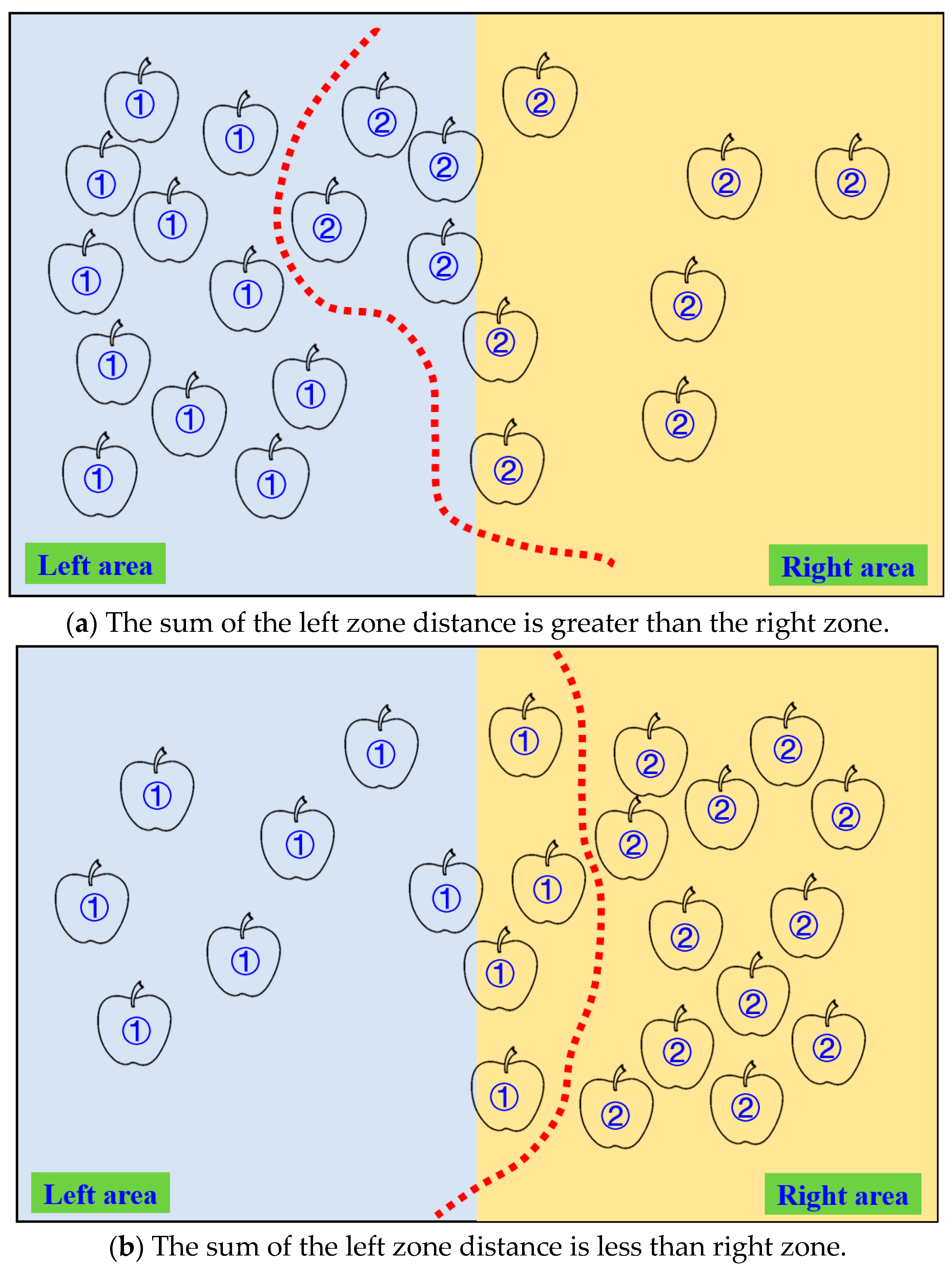
The schematic diagram of the dual-arm dynamic picking-zone method is shown in
Figure 5, including two cases: the left zone distance and greater than the right zone, the left zone distance and less than the right zone. The red dotted line is the dividing line of the dynamic partition. The apple numbered 1 is classified into the left zone after the dynamic partition algorithm, and the apple numbered 2 is classified into the right zone.
V-REP (Virtual Robot Experimentation Platform, Version 3.6.2) represents specialized software for simulating robotic systems, demonstrating particular strength in the kinematic analysis of robotic manipulators. Distributed control architecture can be implemented within this environment using embedded scripts, remote API interfaces, and similar mechanisms, rendering it an excellent resource for robotic simulation. Control algorithms enabling manipulator motion within the simulator can be authored in programming languages such as C/C++, Python, Java, Lua, MATLAB, Octave, or Urbi. Consequently, model visualization is facilitated, and the extraction of relevant simulation data parameters is enabled. The simulation phase is carried out to determine if the two arms can collide during operations.
Because the left and right dividing line of the planned two-arm dynamic picking zones are likely to cross the equidistant line, the two arms may collide when the left and right mechanical arms cross the equidistant line to pick fruits. The simulation diagram of double-arm picking collision when the manipulator has no attitude constraint based on V-REP is shown in
Figure 6. In the figure, the right manipulator crossed the dividing line and entered the left side for operation, and collided with the connecting rod between joints 3 and 4 of the left manipulator.
On the other hand, because the dynamic picking partition method considers the X coordinate size of the fruit centroid in the apple partition, based on the allocation of fruit partition by the robot vision system, there will be no collision between the ends of the left and right picking manipulator, and the collision phenomenon occurs between the end of one manipulator and the link or joint of the other manipulator (as shown in
Figure 6 above), or between the link/joint of the left and right manipulator.
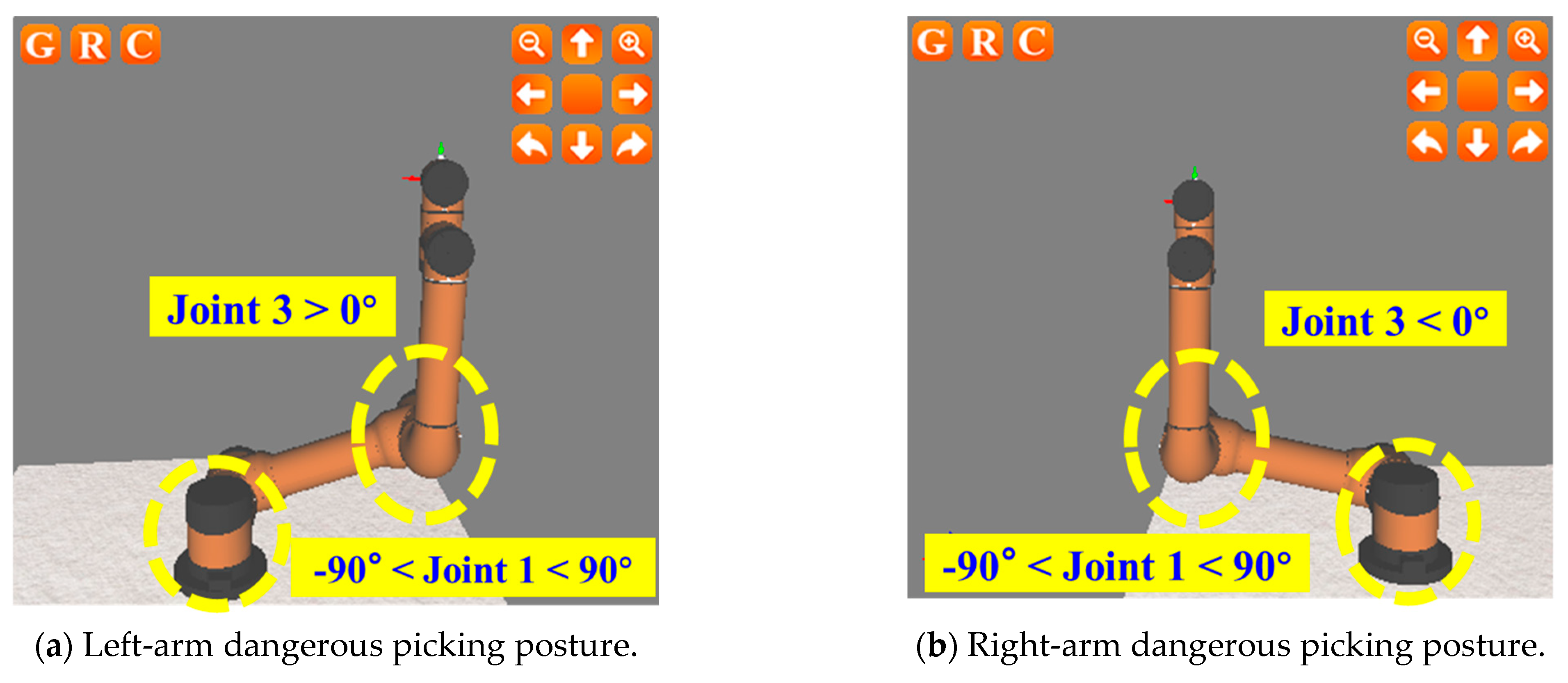
Based on the analysis of the AUBO-i5 six-axis manipulator configuration, if the position and posture of the left and right manipulator in the picking process are constrained, the collision avoidance of both arms in the dynamic picking partition method can be guaranteed. Among them, the picking pose constraints of the manipulator for double-arm collision avoidance mainly involve joint 1 and joint 3 of the manipulator. The specific picking constraint posture of the left and right manipulator is analyzed as follows:
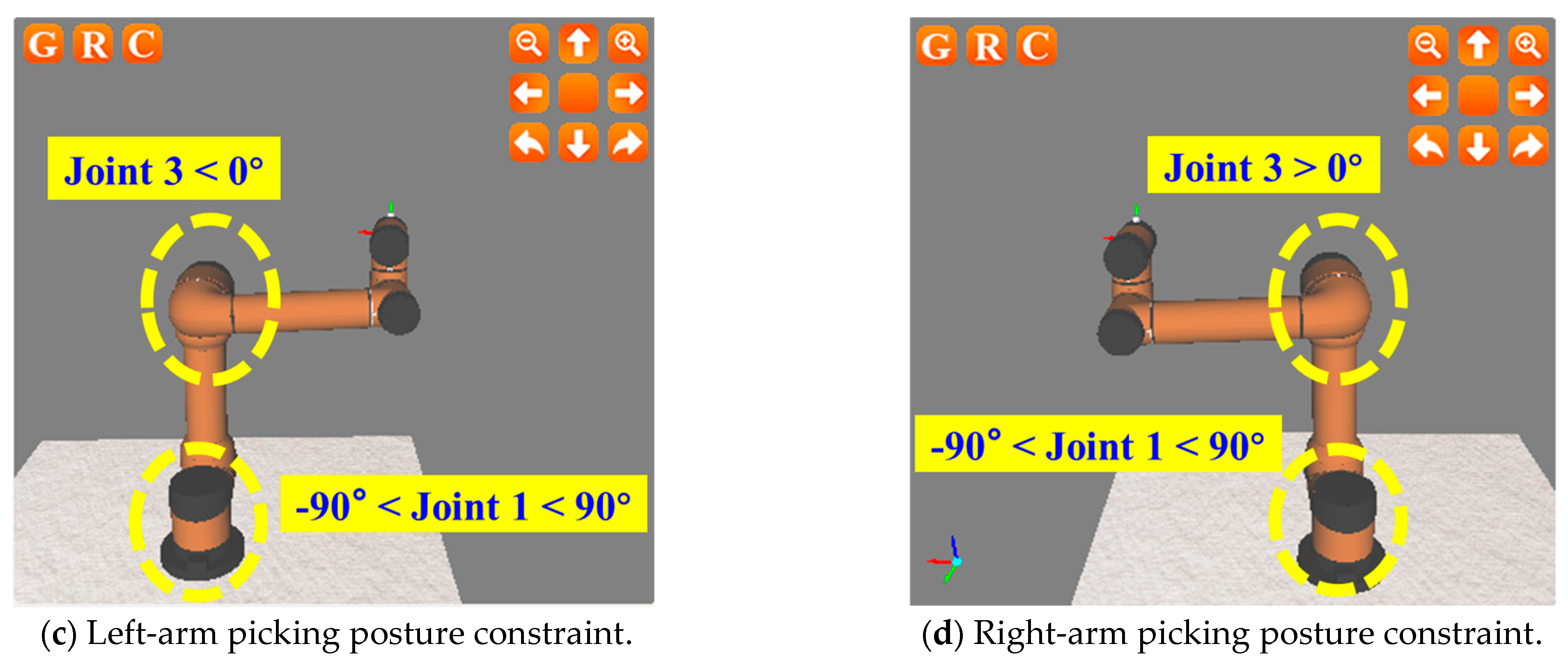
For the left manipulator: when joint 1 is in the range of (−90°, 90°), the picking posture of joint 3 > 0° is a dangerous posture, which easily leads to the collision of both arms (as shown in
Figure 7a); when joint 1 is in the range of (−90°, 90°), the picking posture of joint 3 < 0° is a safe posture (as shown in
Figure 7c).
For the right manipulator: when joint 1 is in the range of (−90°, 90°), the picking posture of joint 3 < 0° is a dangerous posture, which easily leads to the collision of both arms (as shown in
Figure 7b); when joint 1 is in the range of (−90°, 90°), the picking posture of joint 3 > 0° is a safe posture (as shown in
Figure 7d). The analysis of the dangerous/safe picking constraint posture for the left and right manipulators is shown in
Table 1.
Based on the examination of safety constraints for harvesting postures in both manipulators, the preparatory stance for dual-arm fruit collection is defined. Direct movement from the fruit deposition orientation to the apple’s location would cause the robotic arm to encounter interference from arboreal structures; consequently, essential movement constraints must be imposed during the approach and harvesting phases. A predefined preparatory configuration is therefore established—specifically, an intermediary configuration preceding fruit acquisition that must be attained following fruit placement. This ensures harvesting success rates.
Within the dynamic zoning methodology, the end-effector position coordinates (X, Y) in this preparatory stance are configured to match the center coordinates of the manipulator base. The Z-coordinate is set at 50% of the end-effector’s height in the initial vertical orientation (492.5 mm). Crucially, angular limitations for joint 3 differ between manipulators in this preparatory state: the left arm maintains joint 3 below 0°, while the right arm requires joint 3 above 0°. The simulated preparatory configuration for bimanual apple harvesting is illustrated in
Figure 8.
Based on the size parameters of the AUBO-i5 manipulator, the dynamic zoning method of double-arm picking was further analyzed. The top view of dynamic zoning is shown in
Figure 9.
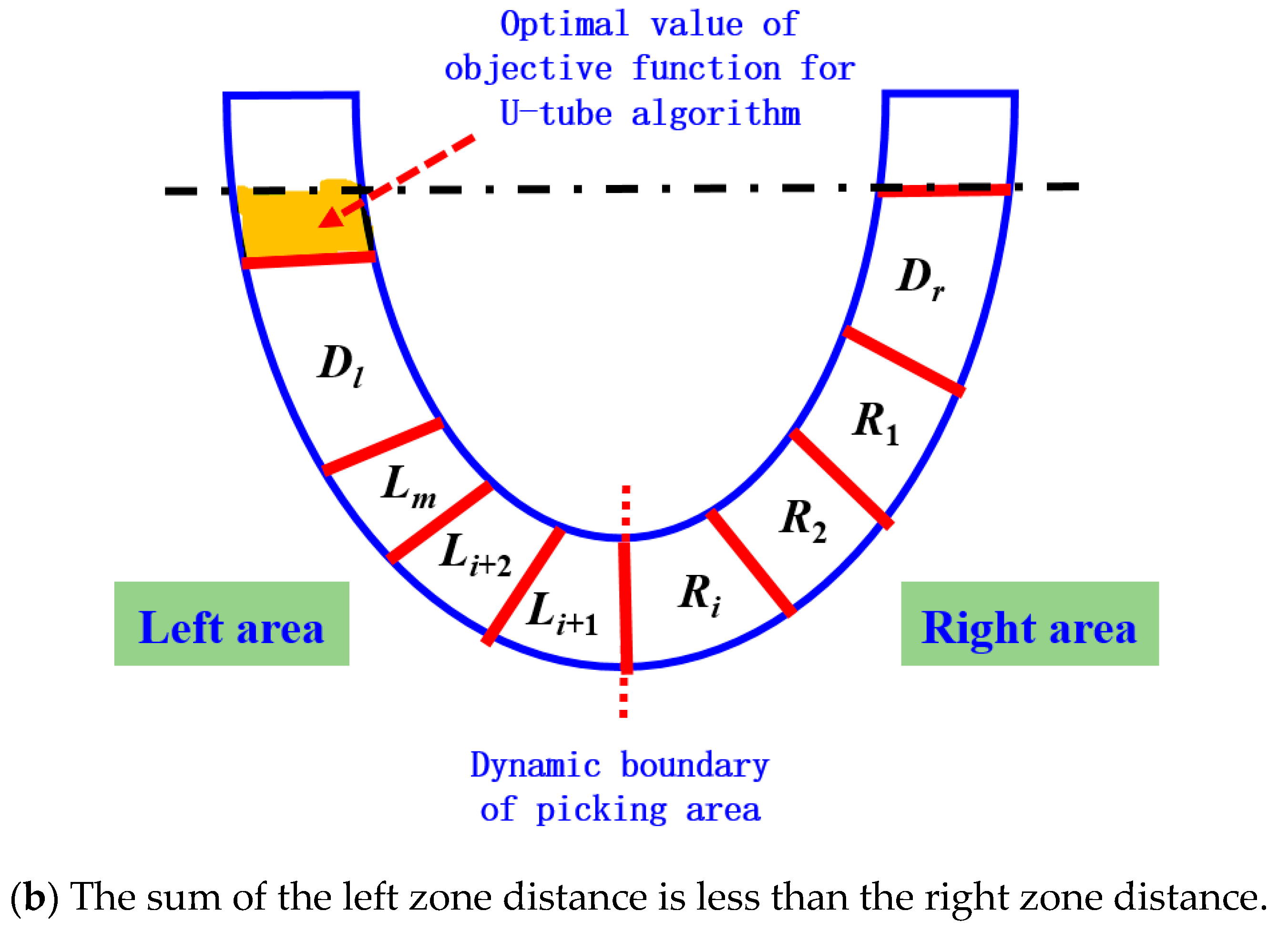
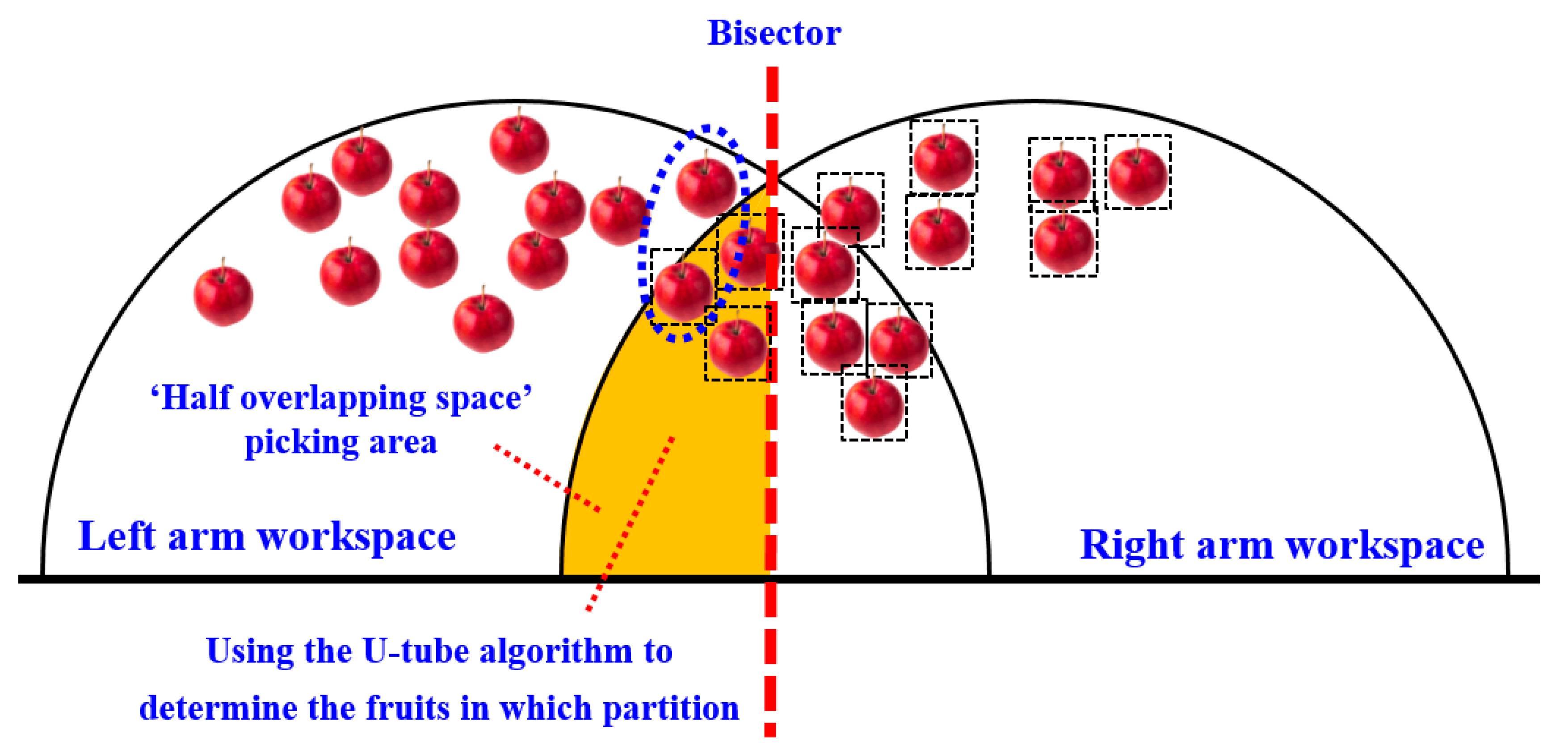
When the sum distance of the left zone is less than the right zone, in order to make the double manipulator work in parallel and at the same time as much as possible, the right manipulator needs to cross the dividing line and enter the left side for picking.
On the other hand, restricted by the arm length of AUBO-i5 manipulator, the right manipulator can only pick fruits within the hemispherical picking range of the right arm on the right side of the dividing line and the hemispherical picking range of the right arm on the left side of the dividing line (as shown in the orange area in
Figure 9a). Therefore, when the distance between the left zone and the right zone is less than the distance between the left zone and the right zone, for all apples within the picking range of the dual-arm robot, the fruits on the right side of the peer line can be directly allocated to the right arm for picking, and the fruits on the left side of the peer line and outside the hemispherical working space of the right arm can be directly allocated to the left arm for picking.
In addition, it is also necessary to plan for picking the fruits in the orange zone (the ‘semi-overlapping space’ picking area marked in orange in
Figure 9a). The planning follows the principle of ‘making the distance and proximity between the left and right zones as far as possible’.
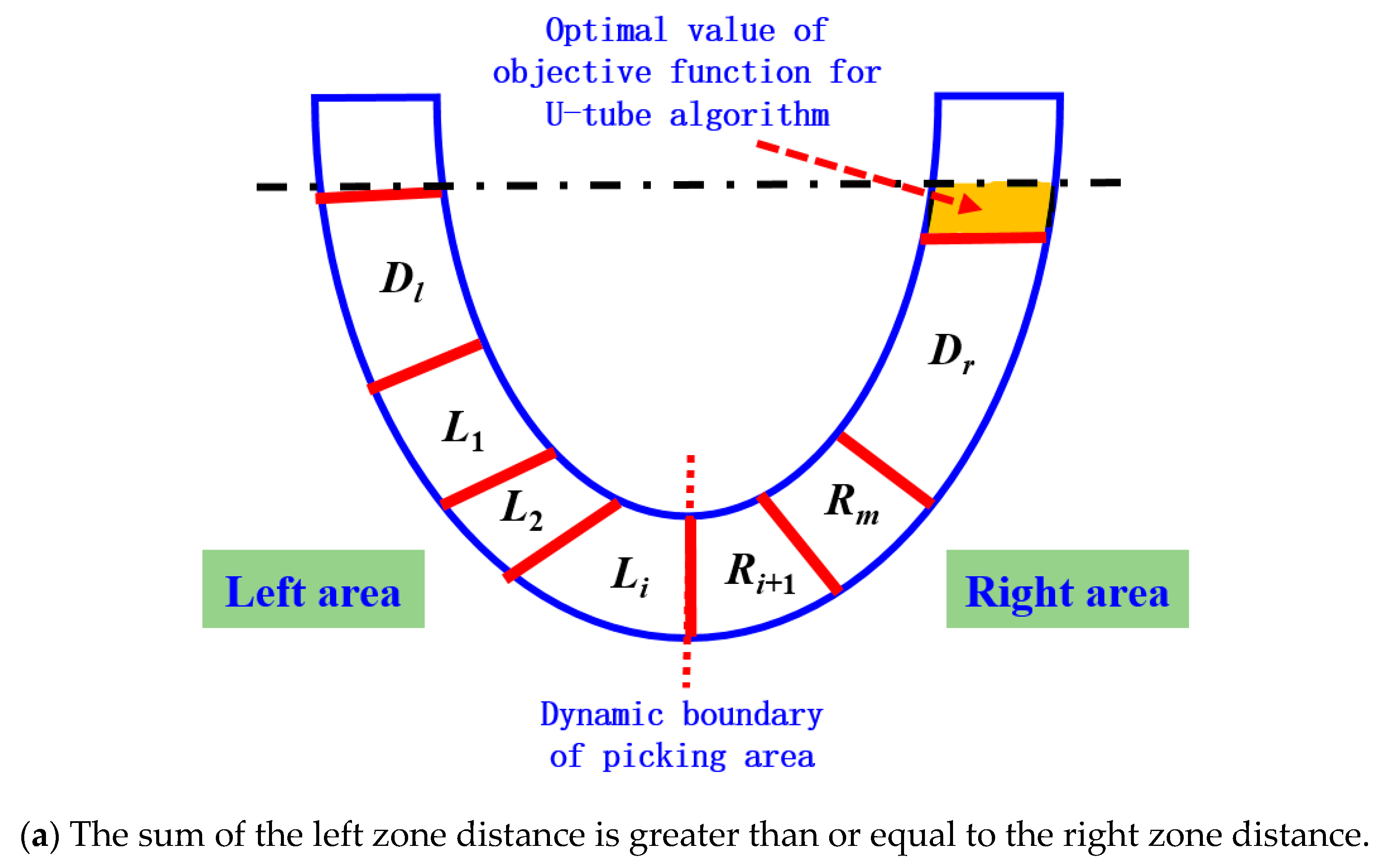
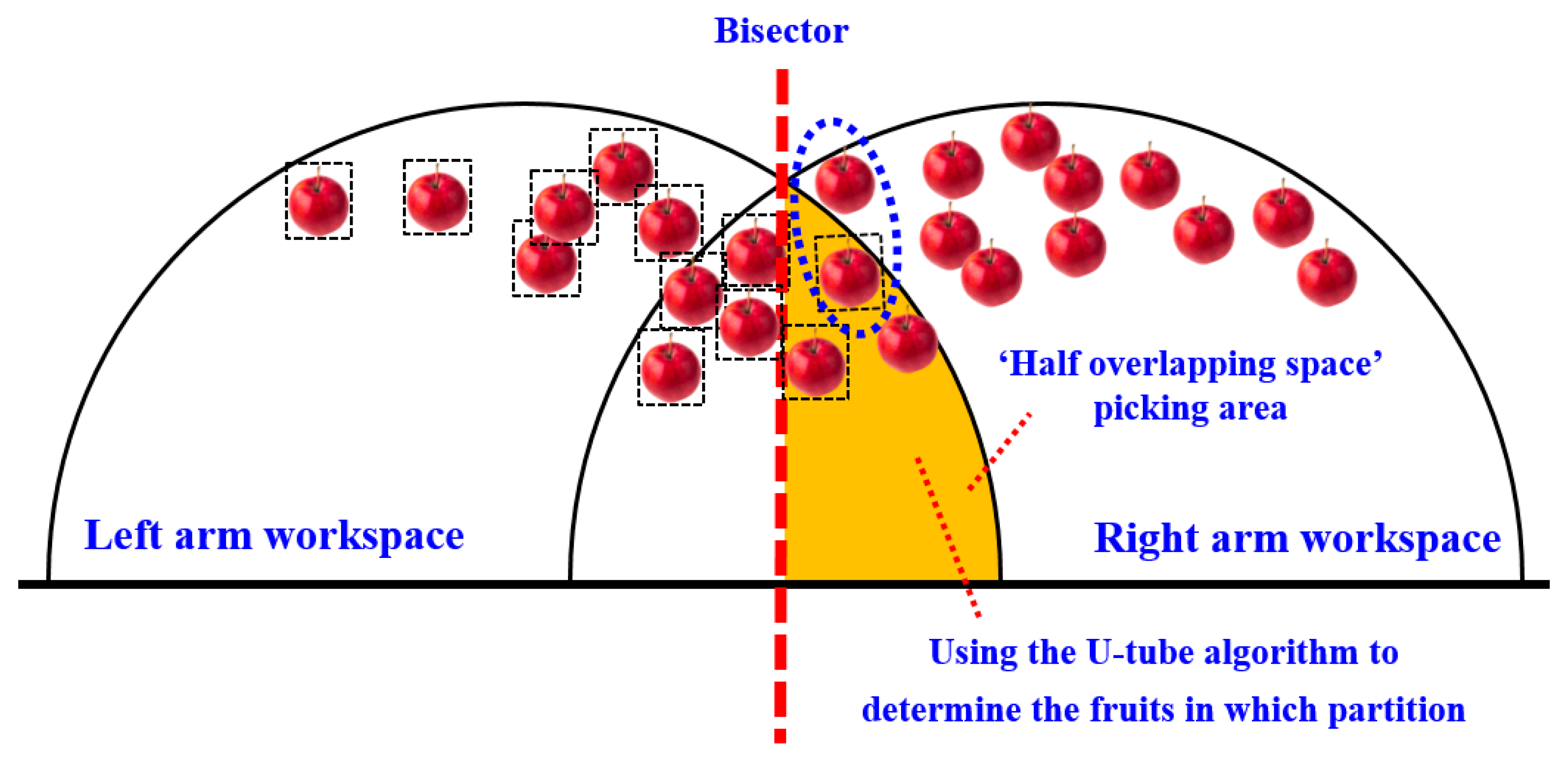
When the sum distance of the left zone is greater than or equal to the right zone, for all apples within the picking range of the dual-arm robot, the fruits on the left side of the peer line can be directly allocated to the left arm for picking, and the fruits on the right side of the peer line and outside the left-arm hemispherical working space can be directly allocated to the right arm for picking.
In addition, it is also necessary to plan for the fruits in the orange zone (the ‘semi-overlapping space’ picking area marked in orange in
Figure 9b). The planning also follows the principle of ‘making the distance and proximity between the left and right zones as close as possible’.
In order to optimize the partition allocation of apples in the picking area of the ‘semi-overlapping space’ in
Figure 9, so as to achieve ‘the distance and proximity of the left and right areas as far as possible’, a ‘U-tube optimal allocation algorithm’ was proposed. The mathematical expression of the objective function of the algorithm is shown in Equations (1) and (2). The goal of the optimal allocation algorithm is to automatically calculate and obtain the zoning plan for apples within the dual-arm picking range that minimizes the value of the objective function.
In the formula, when the distance between the apples to be picked within the picking range of the dual-arm robot and the end of the left arm and DLall is greater than or equal to the distance between the apples to be picked and the end of the right arm and DRall, then the variables are defined as follows:
Dl represents the distance between all fruits located within the picking range of the left arm on the left side of the equivalence line and the end of the left arm.
Dr represents the distance between all fruits located on the right side of the equivalence line and outside the working space of the left arm and the end of the right arm.
L1, L2…Li represent the distances between the apples picked by the left arm from the ‘semi-overlapping space’ picking area on the right side of the equivalence line and the end of the left arm.
Ri+1…Rm represent the distances between the apples picked by the right arm from the ’semi-overlapping space‘ picking area on the right side of the equivalence line and the end of the right arm.
Emin represents the optimal value of the objective function of the ‘U-tube optimal allocation algorithm’ (as shown in the orange area in
Figure 10), and the smaller the value of the objective function, the better the performance of dynamic partition programming.
When the distance between the apples to be picked within the picking range of the dual-arm robot and the end of the left arm, DLall, is less than the distance between the apples to be picked and the end of the right arm, DRall, then the variables are defined as follows:
Dr represents the distance between all fruits within the picking range of the right arm on the equal line and the end of the right arm.
Dl represents the distance between all fruits located on the left side of the equal line and outside the working space of the right arm and the end of the left arm.
R1, R2…Ri, respectively, represent the distance between the apples to be picked by the right arm from the ’semi-overlapping space‘ picking area on the left side of the equal line and the end of the right arm.
Li+1,
Li+2…
Lm, respectively, represent the distance between the apples to be picked by the left arm from the ‘semi-overlapping space’ picking area on the left side of the equal line and the end of the left arm. The orange area in
Figure 10 represents the optimal value (
Emin) of the objective function of the ‘U-tube optimal allocation algorithm’.
The schematic diagram showing the principle of the ‘U-shaped tube optimal allocation algorithm’ is shown in
Figure 10.
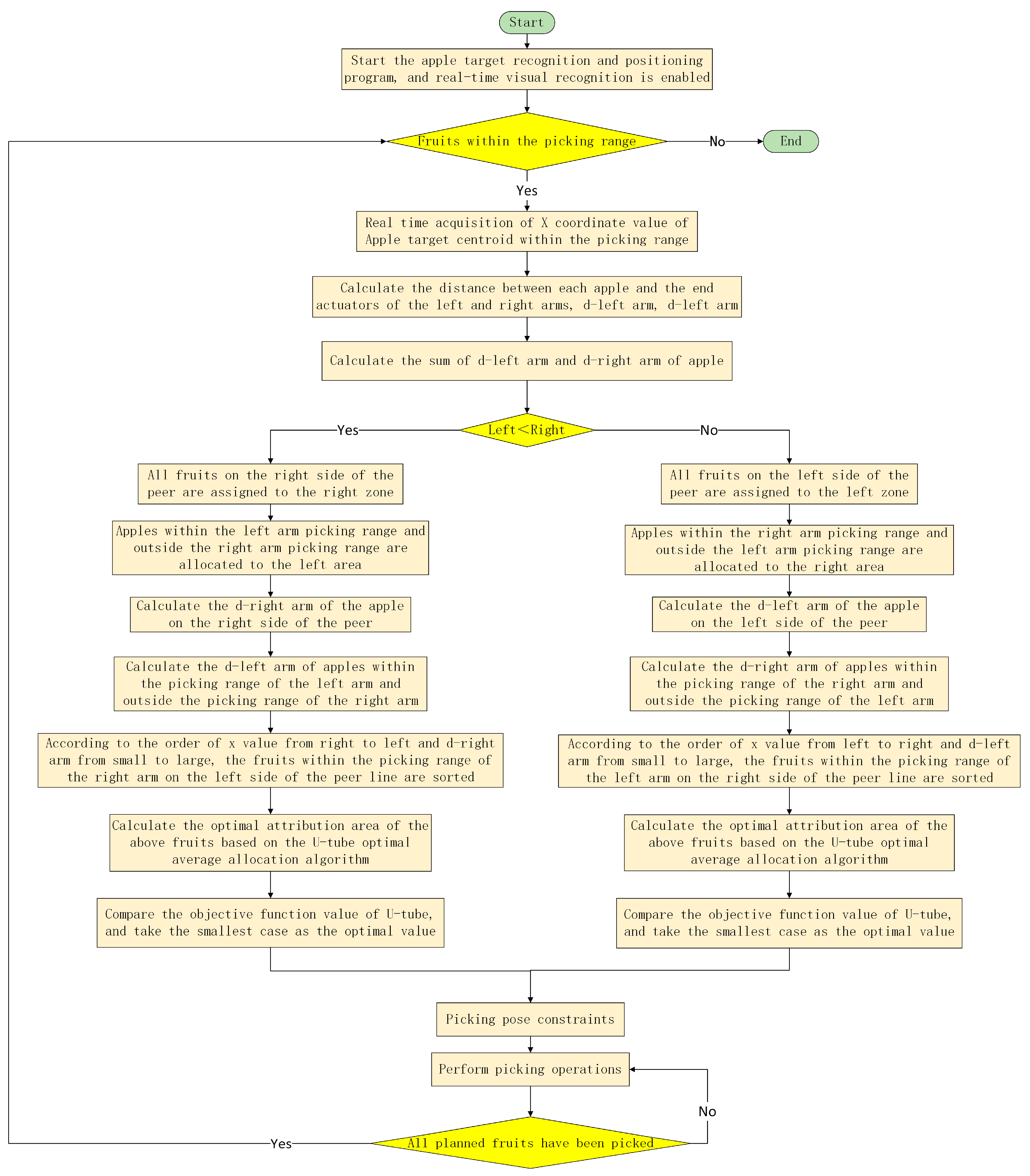
Taking into account factors such as the overlapping layout of the dual-arm workspace, constraints on the picking range of the left and right arms, and constraints on the picking pose, a dynamic partition planning method for dual-arm picking is proposed. The main steps are as follows:
(1) Activate the vision system of the dual-arm picking robot: Start the apple target recognition and positioning program (YOLO-based artificial intelligent detection network for apple targets [
7]) on the robot control terminal, enable real-time fruit target detection, and determine whether there are apple targets to be picked in the space that can be picked by both arms. If there are any, proceed to the next step. Otherwise, keep both arms in a standby state and wait for a target fruit that can be picked to appear in the field of view.
(2) Obtain the x-coordinate value of the center of mass of the fruit: Based on the visual system, obtain the x-coordinate value in the camera coordinate system for the apple target within the range that can be picked by both arms.
(3) Calculate d-left arm and d-right arm separately: Based on the positioning results of the visual system, calculate the distance d between each apple within the picking range and the left-arm end-effector, and the distance d between each apple and the right-arm end-effector.
(4) Calculate DLall and DRall separately: Based on the d-left and d-right arms of each apple obtained in (3), calculate the sum of all d-left arms as DLall and all d-right arms as DRall.
(5) According to the size of DLall and DRall, different partitioning methods are adopted for the fruits:
If DLall < DRall: ① All fruits on the right side of the equivalence line will be assigned to the right area, and the right robotic arm will be responsible for picking them. ② Assign fruits within the left-arm picking range and outside the right-arm picking range to the left area, and have the left robotic arm responsible for picking them. ③ Calculate the d-right arm of the fruit within the picking range on the right arm of the equivalent line. ④ Calculate the d-left arm of the apple within the left-arm picking range and outside the right-arm picking range. ⑤ Sort the fruits within the picking range of the right arm on the left side of the contour line in order from right to left based on the x-coordinate value of the fruit parenchyma center (in ascending order of d-right arm for the same x-value). ⑥ Based on the ‘U-shaped tube optimal average allocation algorithm’, calculate separately the optimal attribution partition for the fruits involved in step ⑤. ⑦ When the objective function value of the U-tube algorithm is minimized, it is the optimal partition, and the dynamic partition result of the current apple to be harvested is obtained.
If DLall ≥ DRall: ① All fruits on the left side of the equivalence line will be assigned to the left area, and the left robotic arm will be responsible for picking them. ② Allocate fruits within the right-arm picking range and outside the left-arm picking range to the right area, which is responsible for picking by the right robotic arm. ③ Calculate the d-left arm of the fruit within the picking range on the left arm of the equivalent line. ④ Calculate the d-right arm of apples within the right-arm picking range and outside the left-arm picking range. ⑤ Sort the fruits within the picking range of the left arm on the right side of the contour line in order from left to right based on the x-coordinate value of the fruit parenchyma center (in ascending order of the d-left arm for the same x-value). ⑥ Based on the ‘U-shaped tube optimal average allocation algorithm’, calculate separately the optimal attribution partition for the fruits involved in step ⑤. ⑦ When the objective function value of the U-tube algorithm is minimized, it is the optimal partition, and the dynamic partition result of the current apple to be harvested is obtained.
(6) Drive the left and right robotic arms to their respective picking constraint positions.
(7) According to the dynamic partition planning method for dual-arm picking, the apple partitioning results are obtained, and the left and right arms, respectively, perform the picking operation.
(8) If all planned fruits have been harvested, return to step (1), otherwise continue with the harvesting operation.
The picking process based on the dynamic partitioning method of the dual-arm picking operation is shown in
Figure 11.
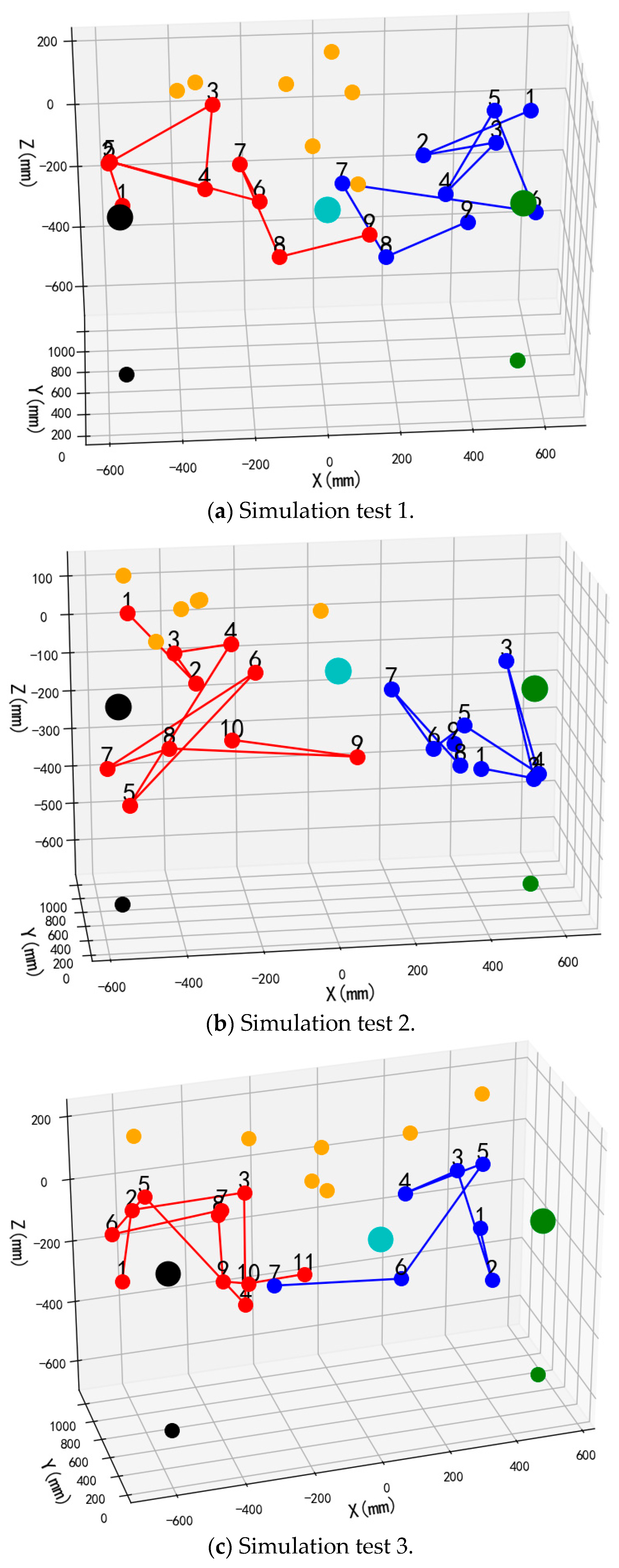
To validate the performance and operational efficacy of the suggested bimanual harvesting dynamic partitioning algorithm within robotic applications, the approach was programmed in Python and fruit traversal simulations were performed. Prior to configuring the simulation trials, spatial coordinates for critical robotic hardware components were established. These included the base centers of both harvesting manipulators, the mounting location of the D435 depth camera, and the end-effector positions for the left and right arms. Distinctive colored markers were applied to essential robotic elements, with the simulation layout depicted in
Figure 12. Crimson markers indicate apples positioned within the left operational zone, azure markers signify fruit located in the right sector, and amber markers represent targets beyond the bimanual harvesting range.
Commencing each harvesting operation from the preparatory stance, the robotic arm initiates apple collection and must revert to this configuration following fruit release before subsequent harvesting. Consequently, the manipulator’s harvesting trajectory can be approximated by the Euclidean distance between targeted fruit and the end-effector in the preparatory configuration. For both manipulators, cumulative linear distances between partitioned apples and their respective end-effectors in preparatory configurations were computed following dynamic partitioning, yielding total operational path lengths for each arm.
Validation of the proposed bimanual harvesting dynamic partitioning method—incorporating pose constraints for collision avoidance—was performed through partitioning simulations utilizing stochastically distributed target coordinates. These simulations were constructed within a MATLAB environment (
Figure 12), with three-dimensional positional data for harvested apples recorded separately for each manipulator. Vermilion markers denote left-arm harvested apples, cerulean markers indicate right-arm harvested targets, and amber markers represent unharvested fruit beyond the bimanual operational range.
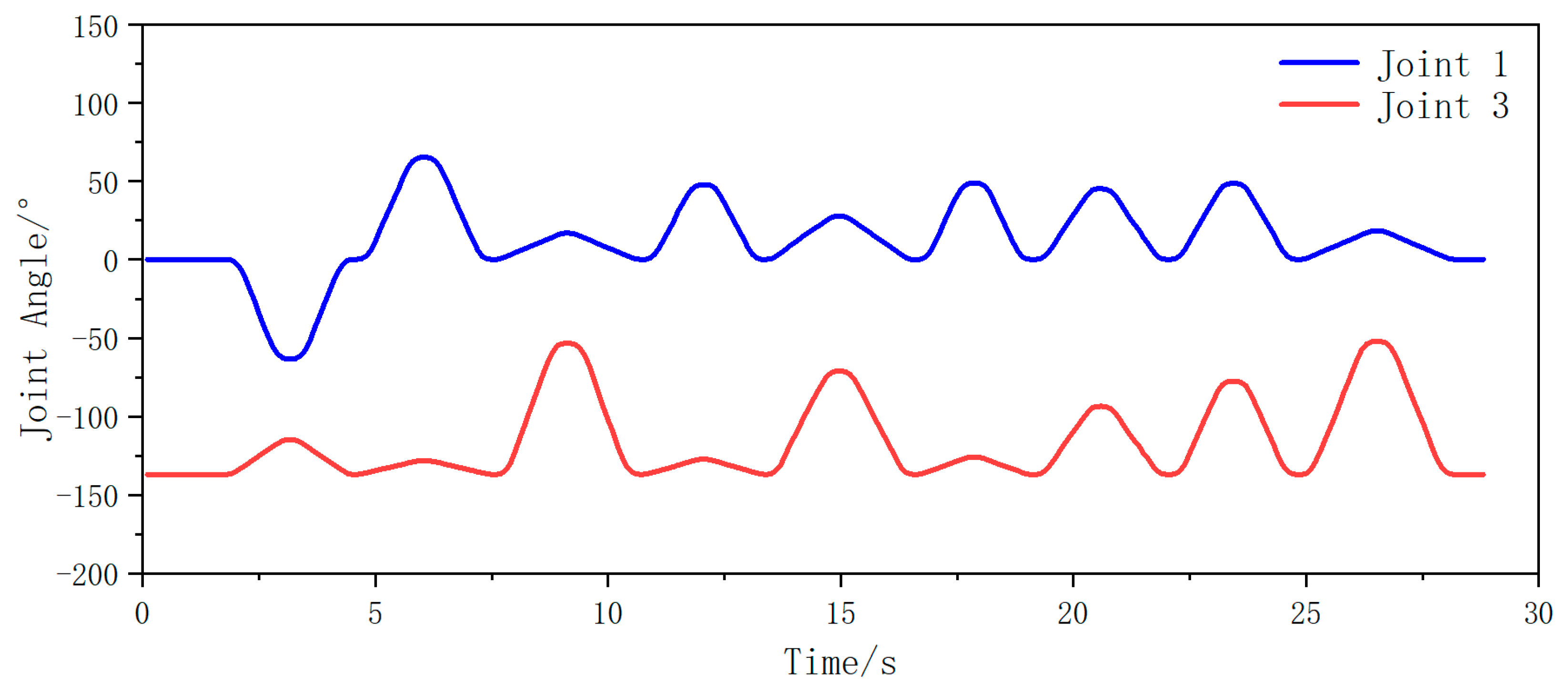
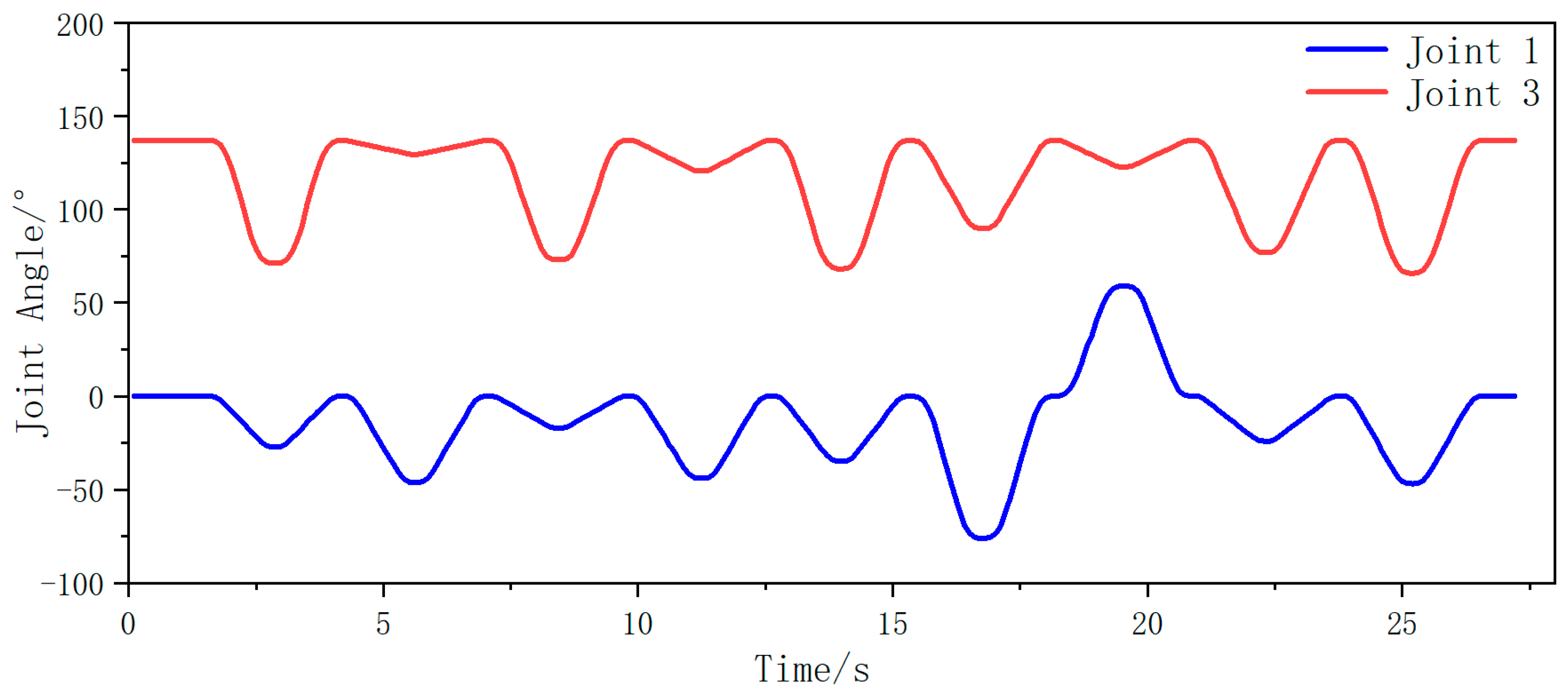
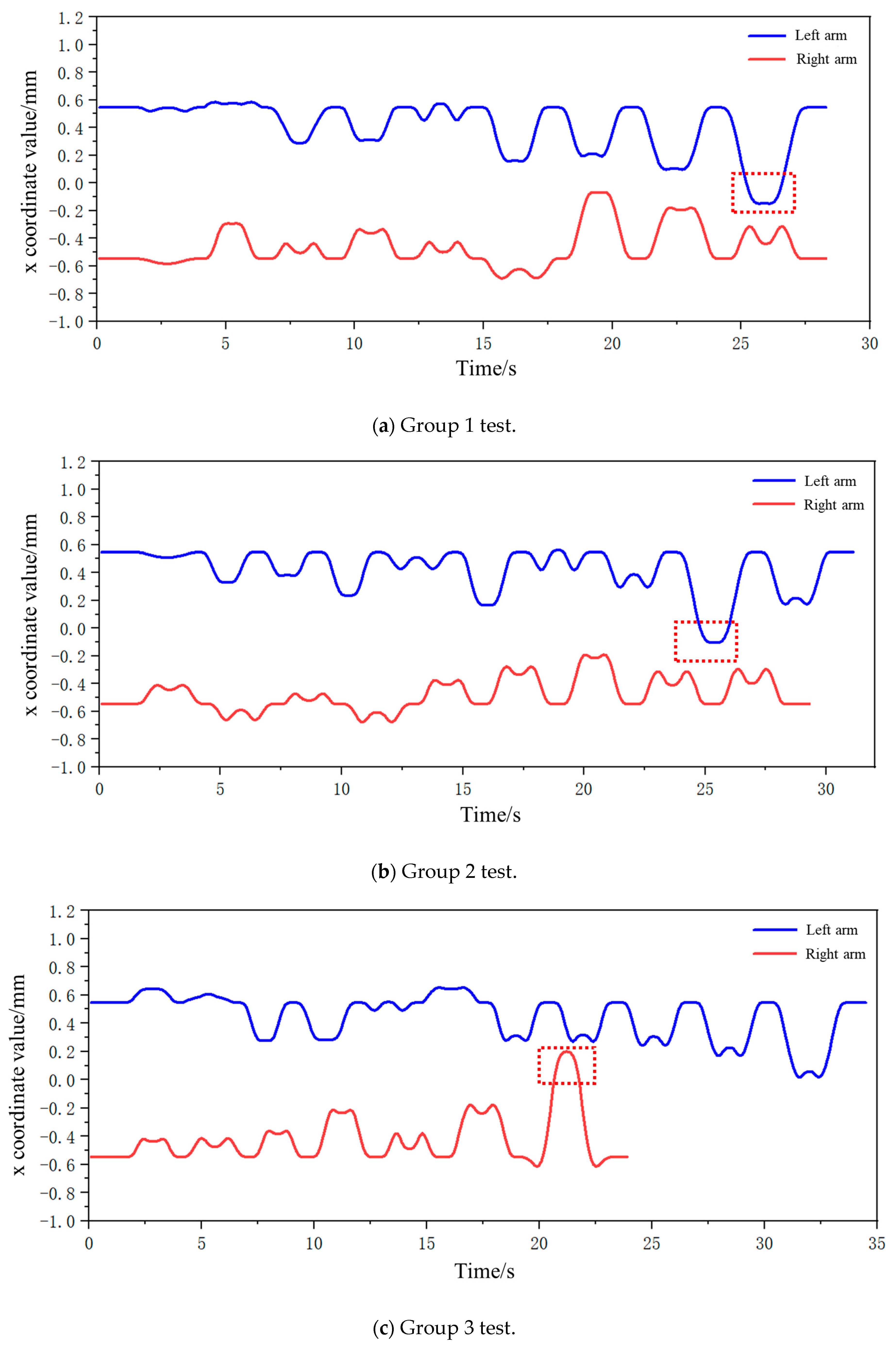
Subsequently, joint angle variations between joint 1 and joint 3 were captured during biaxial motion as both AUBO-i5 manipulators traversed their coordinate sequences. Temporal changes in these joint angles are illustrated in
Figure 13 (left manipulator) and
Figure 14 (right manipulator).
From the analysis in the figure above, it can be seen that during the entire fruit traversal motion of both arms, the angle of joint 1 is always within the range of (−90°, 90°) for the left robotic arm, and the angle of joint 3 is always within the range of less than 0°. Therefore, the motion posture of the left arm is within the angle constraint range of the safe posture. For the right robotic arm, the angle of joint 1 is always within the range of (−90°, 90°), and the angle of joint 3 is always within the range greater than 0°. Therefore, the motion posture of the right arm is also within the angle constraint range of the safe posture. In summary, in the picking traversal workflow based on dynamic partitioning, the motion posture of both arms is within the safe range of pose constraints, and there will be no collision phenomenon.
To enable deeper assessment of the bimanual dynamic zoning algorithm’s efficacy, four experimental series evaluating the dynamic zoning methodology were executed. Each series incorporated two distinct configurations: one where cumulative proximity values for the left manipulator relative to targets in its zone exceeded or matched the corresponding values for the right manipulator (i.e., collective distances from harvestable apples to the left end-effector were greater than or equal to those to the right end-effector), and another configuration where the left manipulator’s cumulative proximity was less than or equal to the right manipulator’s equivalent measurements.
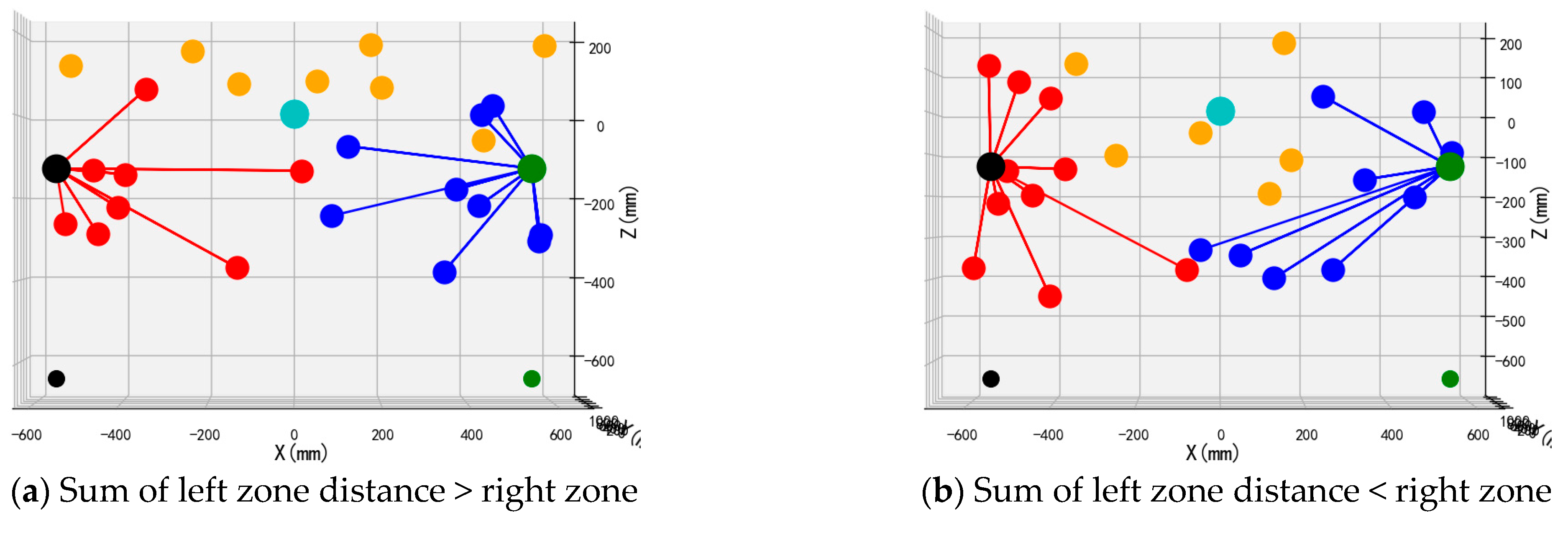
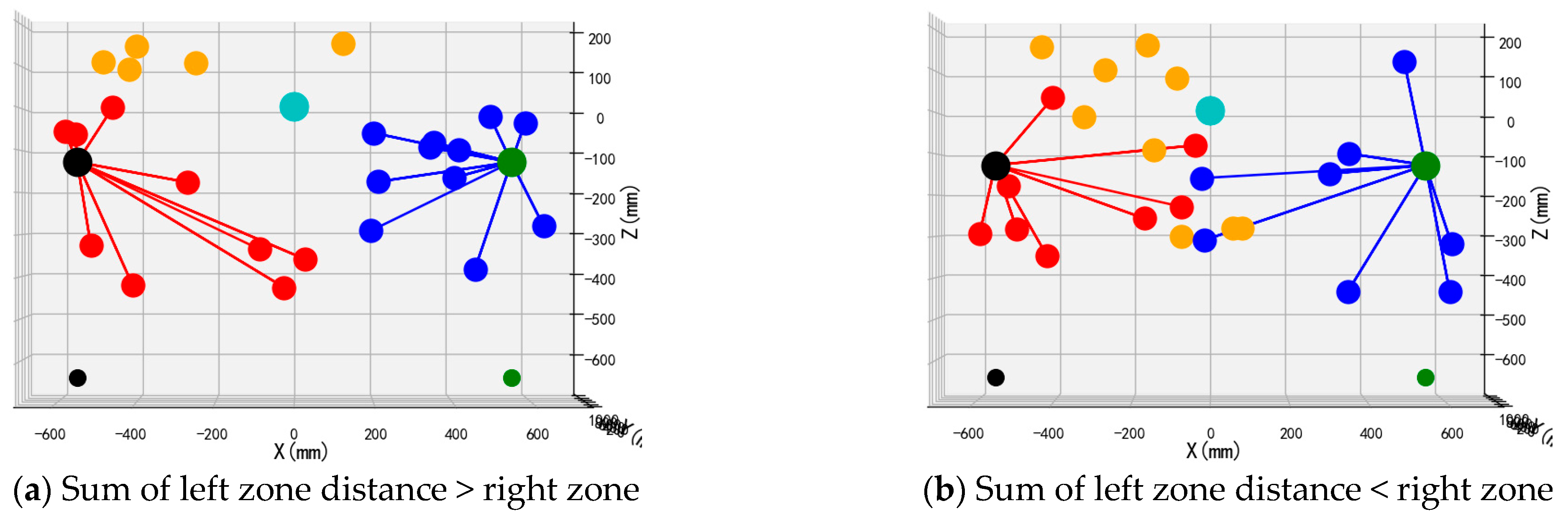
The front views of the 3D schematic diagrams of four sets of simulation experiments for the dynamic partition planning method of dual-arm picking based on pose constraints are shown in
Figure 15,
Figure 16,
Figure 17 and
Figure 18. Vermilion spheres denote targets allocated to the left operational zone, cerulean markers identify fruit positions assigned to the right sector, and amber markers designate unreachable targets excluded from bimanual harvesting.
Simulation outcomes corresponding to dynamic zoning for bimanual harvesting are presented in
Table 2. For every experimental configuration under distinct fruit distributions, multiple parameters were documented: the quantity distribution between left and right operational zones; targets situated within partially overlapping regions; traversal path lengths for both manipulators; aggregate bimanual traversal distance; peak single-manipulator traversal length; and maximum concurrency ratio during coordinated operations.
The tabulated data reveal that across four simulation trials, peak concurrency proportions for coordinated manipulator operations ranged from 82.1% to 99%. Extreme traversal distances between 4404 mm and 6537 mm for individual manipulators were documented, while aggregate bimanual path lengths spanned from 9237 mm to 11,904 mm.
The performance variations observed across the four test groups primarily stem from differences in spatial fruit distribution and the adaptive response of the U-tube optimization-based zoning and sequencing strategy. In groups where fruit distribution was more balanced between left and right zones—particularly when the semi-overlapping space contained an adequate number of fruits—the system achieved higher parallel operation ratios (e.g., 99% in groups 2 and 4) and more symmetric arm travel distances, indicating efficient dynamic task allocation and reduced idle time. Conversely, in less balanced scenarios, such as group 3 with left zone ≥ right zone, where one zone contained significantly more fruits and the overlapping region was limited, the parallel ratio decreased to 82.1% and path lengths became uneven, reflecting a natural adjustment of the algorithm to prioritize collision-free operation over ideal parallelism. Despite these variations, the algorithm consistently minimized total travel distance (e.g., 9237 mm in group 1 under left zone < right zone) and maintained collision-free operation across all cases, demonstrating its robustness in adapting to varying orchard conditions while ensuring operational efficiency and safety.
Applying the principle of ‘maximizing the distance and proximity between the left and right zones’ in the picking dynamic partition planning method, the task allocation for fruits within the dual-arm picking range is carried out. Consequently, regarding harvesting efficiency, maximization of concurrent manipulator utilization is achieved, ensuring peak bimanual coordination ratios and enhancing overall equipment productivity. However, owing to demarcation boundaries being determined by fruit spatial distributions within the current observational scope, harvesting zones frequently extend asymmetrically beyond the central division. This may allocate targets within partially overlapping harvest regions to more distant manipulators, indicating individual apples are not invariably assigned to the nearest available arm. Thus, the aggregate traversal distance for completing harvesting tasks becomes suboptimal—specifically, minimal trajectory requirements for bimanual apple retrieval are not guaranteed—resulting in elevated kinetic expenditure during robotic harvesting operations.
