1. Introduction
China is experiencing an unprecedented urbanization process, with the urbanization level increasing from 17.92% in 1978 to 59.58% in 2018 [
1]. With the acceleration of urbanization, the expansion of urban and population growth has led to an increasing demand for cultivated land, resulting in unreasonable land use. Large amounts of farmland have been occupied and converted into other uses, such as residential, industrial, commercial, infrastructure, and institutional uses during the period of urban expansion [
2]. Meanwhile, idleness of cultivated land is pervasive in rural areas as a consequence of urbanization or unclear ownership. As China is a developing country with a large population and scarce land resources, the loss of cultivated land will threaten the security of food supply and the stability of society. In this respect, accurate monitoring of cultivated land plays a crucial role in farmland preservation.
In order to ensure the basic food supply for human survival, Chinese government has formulated a series of policies to protect the total amount of cultivated land, such as the delineation of basic farmland protection zones (BFPZs) [
3,
4,
5]. When a piece of land is determined as basic farmland by the land management department, it means that the land use type within the delimited boundaries cannot be changed into non-cultivated land use. If changed, it will be regarded as illegal occupation of farms. Therefore, the focus of cultivated land monitoring is to check whether there is deduction of farms and change in land use type in the delimited area over a period.
Generally, the methods used for monitoring cultivated land can be classified into two categories: field survey and remote sensing technologies. Traditional field survey method can provide more accurate results than other approaches. However, it requires considerable manpower, which can be time consuming and expensive. For the methods of using satellite remote sensing, emerging studies are mainly focused on landform classification, which is an effective way for dynamically monitoring land use and land cover changes. It is noted that Landsat series of images are widely used to detect and monitor land use change, as they are freely available in forms of different spectral, resolution, and time, supporting continuous and long-term monitoring land use change in large areas [
6,
7]. However, the low spatial and temporal resolution of satellite images will limit its ability to detect and monitor land use in small sized and scattered distribution land [
8]. Additionally, it is difficult to use satellite images to identify the problems of land degradation, illegal occupation, and land idleness within a certain period and time. UAVs (unmanned aerial vehicles) images seem to be an alternative remote sensing tool for the detection of land use change, due to its advantage of strong mobility and high efficiency [
8,
9,
10,
11]. Nevertheless, UAVs cannot work continuously for the monitoring of cultivated land for some reasons. UAVs are easily affected by weather conditions, complex terrain, airspace regulations, and other factors in some places. Moreover, images acquired by UAVs may contain severe geometric and radiometric distortions, which challenges the automatic processing of UAVs images and hampers the application of UAVs [
12,
13].
Nowadays, numerous intelligent surveillance cameras have been mounted in public places due to its increasingly significant role in traffic monitoring, public security, and other applications. Intelligent video surveillance can automatically detect, track, and recognize interested objects, and analyze their activities to extract useful information from collected videos [
14]. Moreover, it can remotely transmit real-time images, audio, and other data to the central control room through the Internet, which offers great potential for monitoring cultivated land. In comparison with satellite remote sensing and UAVs technology, it can work continuously with higher spatial and temporal resolution with less manual intervention. What is more, it is more suitable for monitoring small size and scattered distribution land. However, there are various problems when the conventional intelligent video surveillance is directly applied to cultivated land monitoring. For example, the unauthorized conversion of certain farmland can be detected early by intelligent video surveillance, while regulars cannot quickly identify the location, including the coordinates or other semantic information of the land. When the number of surveillance cameras grows larger, it is more difficult to manage the cameras and fragmented video data [
15]. More importantly, it is hard to define the boundary of cultivated land (region of interest) in every video image when the camera is panned, tilted or zoomed.
BFPZs delimited by the land management department define the boundary of protected cultivated land, and it is usually presented and stored in forms of vector data. The integration of intelligent video surveillance and 2D vector BFPZs data provides a new opportunity for solving the above problems. As video is composed of a sequence of separate frames (images), it is essential to establish the relations that map the frame’s pixels with corresponding geographic locations for each frame to integrate GIS and video [
16]. At present, the general method is to directly project video frames into a virtual 3D (three-dimensional) GIS scene, which requires both precise 3D models of the surroundings and camera pose estimation [
15,
16,
17]. In this case, video frames do not match the intuitive feeling of the human eye because they have been geometrically corrected to the 3D GIS scene. Furthermore, it is difficult to obtain accurate real-world physical information of acquired images due to changes in focal length and angles of the PTZ (pan-tilt-zoom) cameras. Moreover, high resolution DEM (digital elevation model) or DSM (digital surface model) are not always accessible. Another method is based on a homography transformation, which assumes a planar ground in geographic space and requires at least four corresponding points to calculate the homography matrix parameters [
18]. Both of the two methods rely on matching corresponding points in video image space and geospatial space [
19]. It is a challenge to automatically match features from video image and GIS data. For PTZ cameras, it is not advisable to manually select points considering the cost and work efficiency.
Based on the above analysis, the main objective of this paper is to propose an accurate matching method for projecting vector data into surveillance video to monitor and protect the cultivated land. It mainly relies on matching the 2D image coordinates from PTZ video frames with orthophoto maps and vector surveying and mapping data. On the basis of the proposed method, we design and implement a prototype of cultivated land monitoring system. Then, the implemented prototype is applied to monitor cultivated land in Dongyang City, Zhejiang Province, China.
2. Related Work
Currently, several GIS-based video monitoring systems have been developed and applied in the fields of city safety management and forest insect defoliation and discoloration [
17,
18]. Inspired by these systems, this paper develops a new video and GIS integrated surveillance system for cultivated land, which can make up for the shortcomings of traditional field surveying and remote sensing technologies. In this section, we mainly introduce the related work on the integration of video and GIS.
The study mainly focuses on establishing the geometric mapping relationship between the spatial point set sampled from video frame and the geospatial point set sampled from geodetically calibrated reference imagery. Since the video is composed of a series of independent frames (images), the geometric mapping relationship should be constructed for each frame.
At present, the methods for video geo-referencing can be classified into two categories: methods based on view line intersection with DEM and methods based on a homography transformation [
18,
19,
20]. For methods based on the intersection between sight and DEM, precise parameters including inner and outer camera parameters and DEM are required to project video frames into a 3D model of an area that is being watched. For example, Zhao et al. [
17] proposed a video-based monitoring framework for forest insect defoliation and discoloration. GIS data and Video Surveillance could be integrated to determine the geographical position of forest insect damage in their monitoring system, which required a digital elevation model (DEM) and returned parameters from the PTZ camera. Milosavljevic et al. [
19] proposed a method to estimate the geo-reference of both fixed and PTZ cameras, which relied on matching 2D image coordinates from video frames with 3D geodetic coordinates to estimate the camera’s position and orientation in geographic space. In this situation, video frames do not match the intuitive feeling of the human eye because they have been geometrically corrected to the 2D or 3D GIS scene. Furthermore, it is difficult to obtain precise real-world physical information of the acquired images due to changes in focal length and angles of the PTZ cameras. Meanwhile, high resolution DEM or DSM are not always available and not all of the objects in real world can be modelled, which causes the failure of cross-mapping.
Methods based on a homography matrix assume a planar ground in a geographic space, so they require at least four matching points to estimate the corresponding homography matrix [
21]. Automatically detecting and matching features from ground imagery or stationary videos, such as surveillance cameras videos, and satellite or aerial images can be defined as cross-view image matching [
22,
23,
24]. It is almost impossible to automatically match features from such images due to the dramatic differences in each set of images, as they are captured from different viewpoints and in different resolutions. Therefore, the matching points are manually selected from cross-view images. The number, precision, and spatial distribution of the selected points are very important and directly affect the accuracy of image registration. For 2D GIS, the mapping from 2D geographic space to video image space is double, but for 3D GIS, the transformation is single [
18]. When using these methods, the terrain model is usually taken into account for the assumption of planar ground. The main drawback of these methods is that they are unsuitable for the case of PTZ cameras. With the change of pan-tilt-zoom, more user interaction is required to select corresponding features and prevents automation.
3. Methodology
The proposed method for integrating a surveillance video and BFPZs (2D GIS vector data) relies on registering BFPZs to surveillance video image. This can be realized by the mapping matrix estimated by matching the 2D geodetic coordinates with the 2D image coordinates in video frames. Compared to fixed camera, PTZ cameras can be controlled to rotate horizontally and vertically, and the field-of-view can be changed. The image coordinates of each video frame are independent of other images. Therefore, we need to construct the mapping relationship between BFPZs data and every video image.
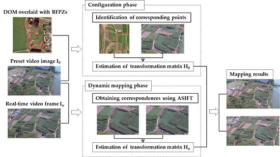
As there is large resolution and geometric difference in the two types of data, it is impossible to automatically detect and match features. Therefore, we break down the integration process into two stages, as shown in
Figure 1. In the configuration phase, we will determine the mapping relationship between BFPZs and the preset video image
. by identifying corresponding features from the two data and estimation algorithms. DOM (digital orthophoto map) is used to help identify corresponding points in the BFPZs and preset video image, as vector data is graphics and hard to be recognized. Based on these features, the transformation matrix can be estimated by algorithms. Then, the coordinates of 2D BFPZs can be transformed from geodetic space to video image space. In the dynamic mapping phase, the mapping between 2D BFPZs and PTZ video images can be seen as the problem of multi-view image matching since BFPZs has been projected in image space. Different from configuration phase, we can use a matching method to automatically detect and match points without manual intervention. Once the relative geometric relation between video frames is estimated, then the coordinates of 2D BFPZs can be transformed between different video image space. In the following sections, we will introduce the details about homography transformation, SIFT (scale-invariant feature transform) [
25] and ASIFT (affine-SIFT) [
26] matching algorithms and the integration strategies.
3.1. Homography Transformation
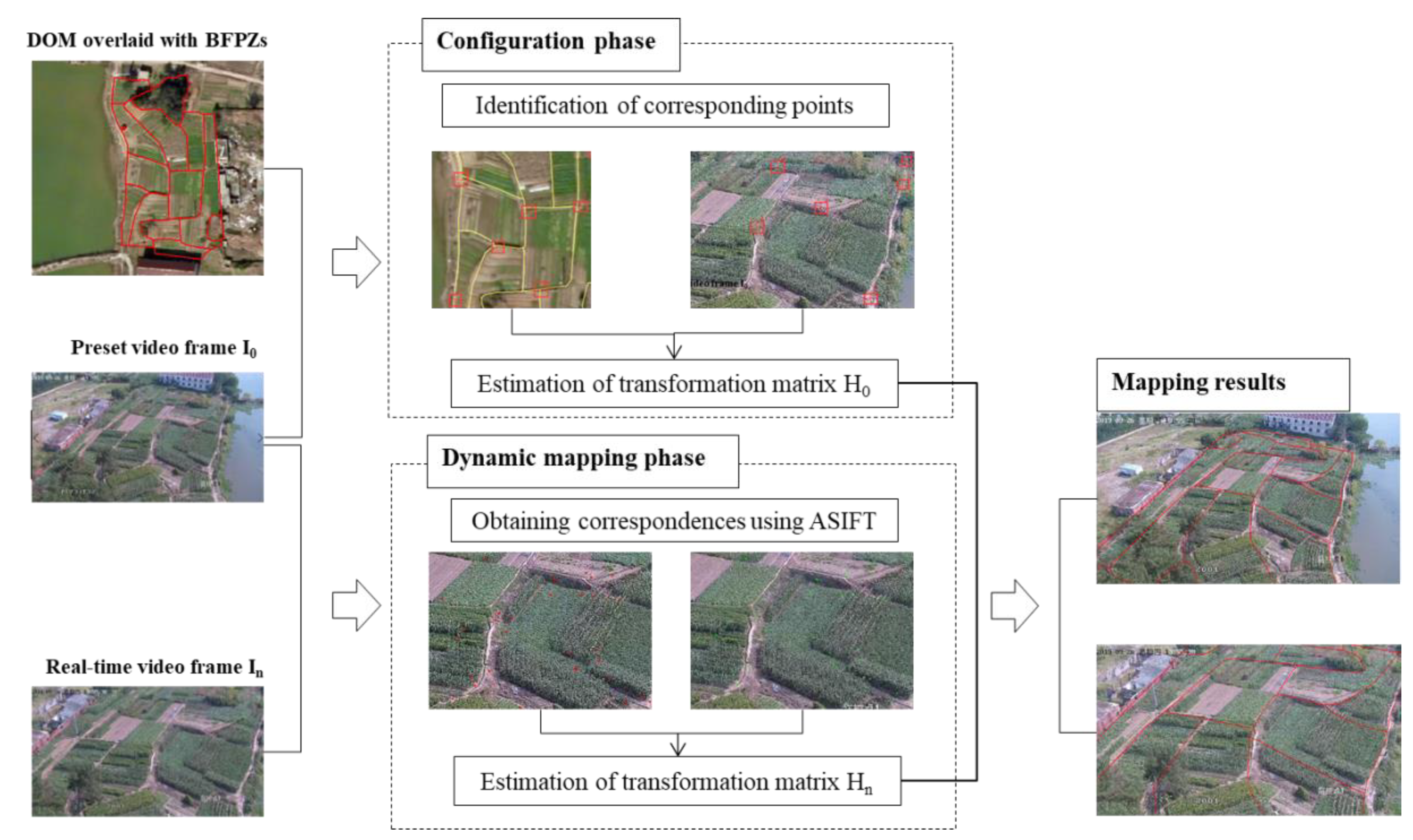
The homography transformation is a popular geo-referencing technique used worldwide. Surveillance video and remote sensing (RS) sensors capture the same scene differently in two views, i.e., front view and side view, as shown in
Figure 2. Usually, the remote sensing images are geometrically corrected and used to produce a DOM. When the terrain is a planar ground or the topographic relief is small, the complex geometric relations between surveillance video image and remote sensing image can be modelled by homography transformation.
Assuming
is a point in the DOM spatial coordinate system, and its corresponding point in video image coordinate system is
:
where
and
are real world coordinates,
and
are column and row, respectively, in image coordinates.
Given a homography matrix
, the relationship between
and
can be expressed as follows:
is a
matrix and can be represented as follows:
As
has eight unknowns, at least four pairs of non-collinear video image point and geospatial points are required to calculate the parameters of
. Once
is determined, the coordinates of any point in spatial coordinate system can be projected into the image coordinate.
The mapping is double direction, and image coordinates can also be projected into the spatial coordinate system. This modeling method is convenient for geometric presentation, computation, and implementation simplicity.
3.2. SIFT and ASIFT Matching
When the PTZ surveillance camera is paned, tilted, or zoomed, there will be geometric distortion between these video sequences. To automatically integrate GIS data and surveillance video, we use the image matching algorithm to automatically detect and match corresponding features, rather than manually selecting feature points.
SIFT [
25] is a well-known image matching algorithm, which is invariant to scaling, rotation, illumination, and affine transformation with sub-pixel accuracy. The original SIFT algorithm first uses subpixel location, scale, and dominant orientation to describe a detected feature point. It can be expressed by
, where
represents the location of the feature,
and
denote the point’s characteristic scale and dominant orientation, respectively, and
is a 128-vector invariant feature descriptor. Then, feature points are matched using the minimum Euclidean distance method between their descriptors. To ensure correct matching, Lowe [
25] suggested another matching strategy called NNDR (nearest neighbor distance ratio), which means that the ratio of the nearest to the second nearest neighbor can be applied to get correct matches. It can be described as follows:
where,
means the Euclidean distance from the nearest vector in sensed image feature map to the vector in reference image feature map and
is the Euclidean distance from the second nearest vector in sensed image feature map to the vector in reference image feature map. When the distance ratio is lower than
, it can be seen as a pair of correct matches.
However, SIFT does not perform well when geometric distortion between images is severe. In order to improve the performance in this situation, ASIFT [
26] is proposed, which simulates the rotation of camera around optical axis. In their method, image affine transformation is applied to model the changes of viewpoints, which can be expressed as:
The processing steps of ASIFT can be summarized as follows: first, a dense set of rotation transformation is applied to both images A and B; then a series of tilt transformation is applied to all rotated images; at last, SIFT is performed to match all pairs of the simulated images.
3.3. Integration of 2D Vector BFPZs and Surveillance Video Images
In the proposed method, the mapping between 2D Vector BFPZs and PTZ surveillance video is constructed in a semi-automatic way. To solve the homography matrix between BFPZs data and the preset frame of PTZ camera, we provide an interactive tool to select control points. Once an adequate number of points are matched, Levenberg–Marquardt iterative optimization [
27,
28], is applied to calculate the homography matrix.
Assuming that 2D Vector BFPZs is a set of polygons
, for a given polygon
, and the coordinates of its vertex are
. Then this vertex can be mapped into an image coordinate system, and its coordinates are
, which can be computed as follows.
where,
,
,
,
,
,
,
,
, are parameters of
.
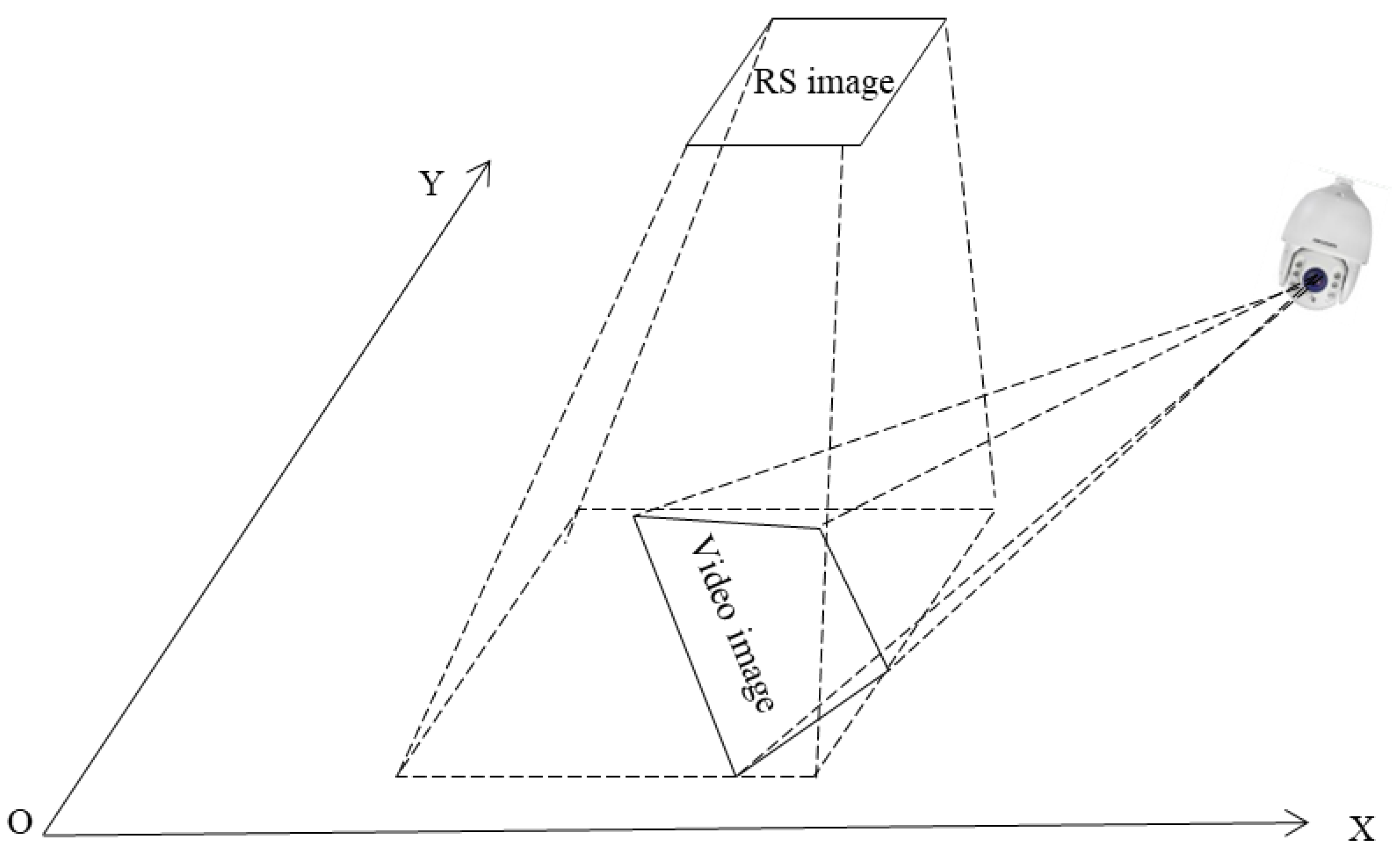
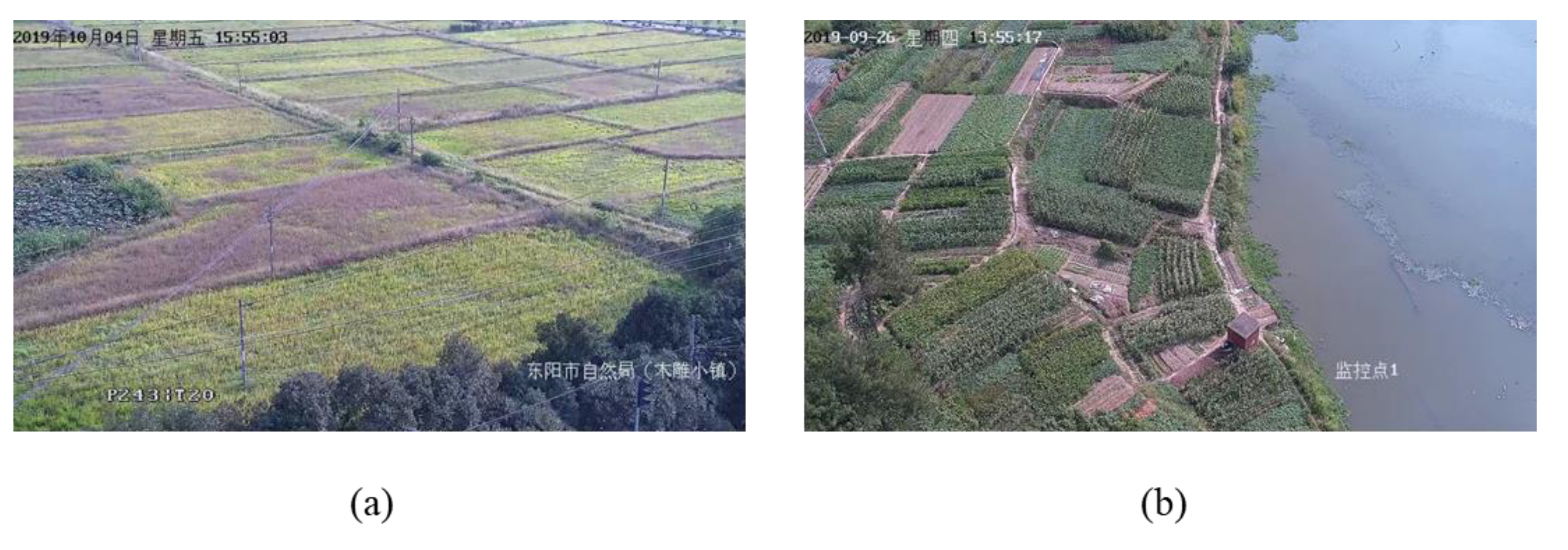
The precision, number, and spatial distribution of the selected points play a vital role in the process of calculating the homography matrix, which directly affects the accuracy of the estimated matrix. It is better to choose relative permanent points, such as road intersection, as shown in
Figure 3.
When the PTZ camera is paned, tilted, or zoomed, the homography matrix between GIS data and video frames can be calculated as follows. First, ASIFT matching method is used to detect and match features from video sequences. Then, random sample consensus (RANSAC) [
29] is applied to estimate the homography matrix between video frames, considering that the obtained corresponding features have mismatches even using the best automatic matching method. RANSAC estimates the parameters of homography model from a set of observed data containing outliers in an iterative way. Finally, the mapping between 2D Vector BFPZs and any video frame can be calculated.
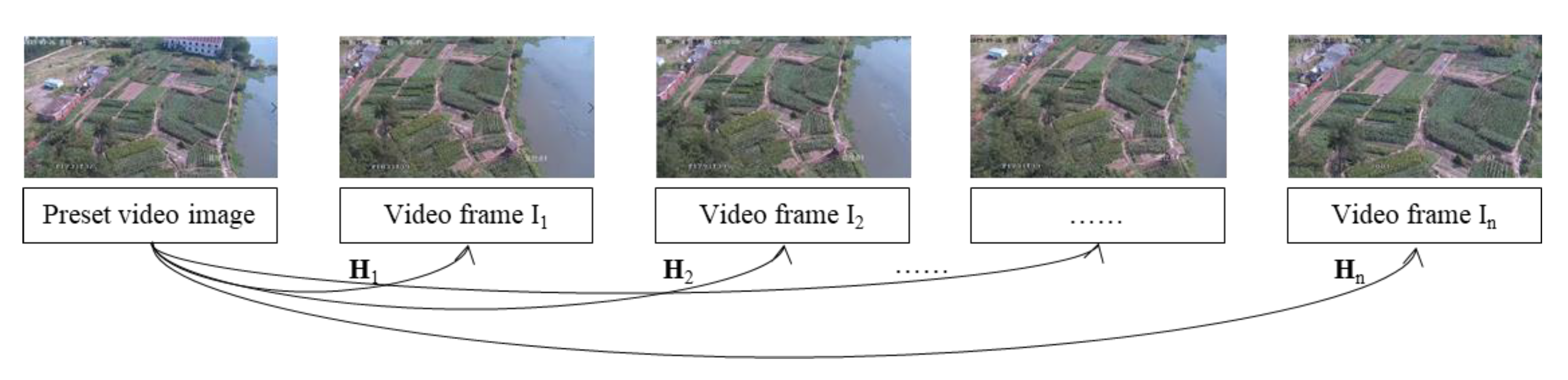
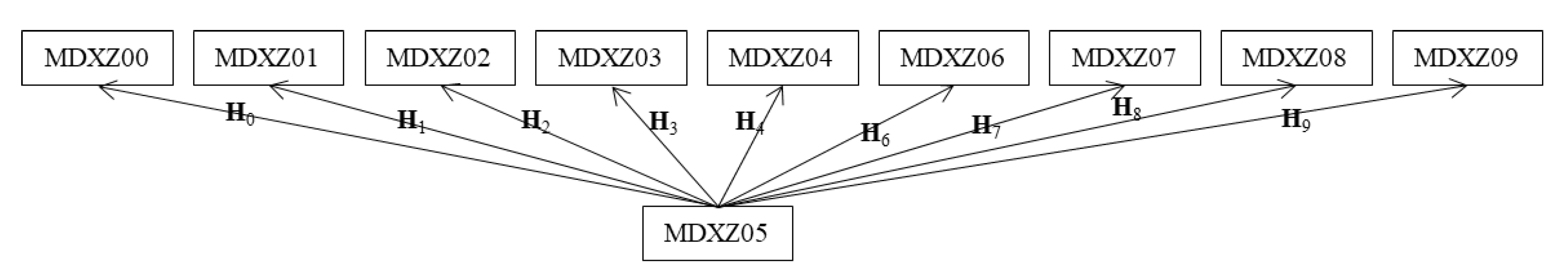
Specifically, the locations of 2D Vector BFPZs in each single video frame coordinates system can be computed by two strategies. What counts is the selection of reference video frame. If the preset video frame is chosen as the reference image, ASIFT and RANSAC methods are applied to estimate the mapping matrix between video frames and preset image. As shown in
Figure 4, assuming that the estimated transformation matrix between reference frame and frame
is
, and any vertex
of the BFPZs polygons in video frame
can be calculated using its corresponding vertex
of the BFPZs polygons in reference frame as the following equation.
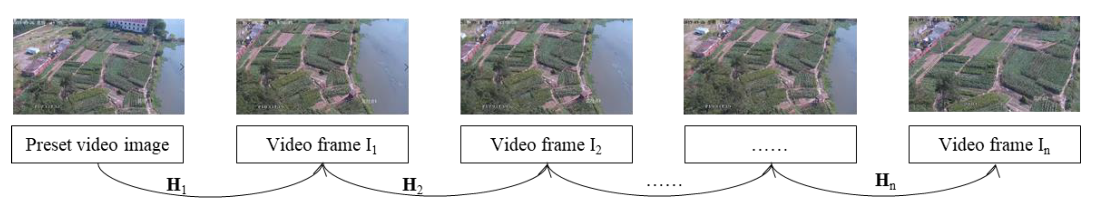
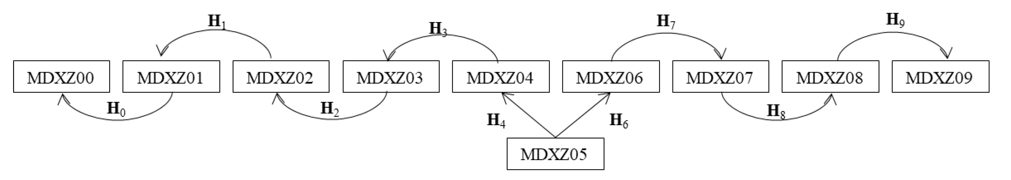
Image matching is performed between adjacent video frame, as shown in
Figure 5. In this situation, vertex
of the BFPZs polygons in video frame
can be computed as Equation (10).
where
is the transformation matrix between video frame
and
.
4. Framework of Cultivated Land Surveillance System
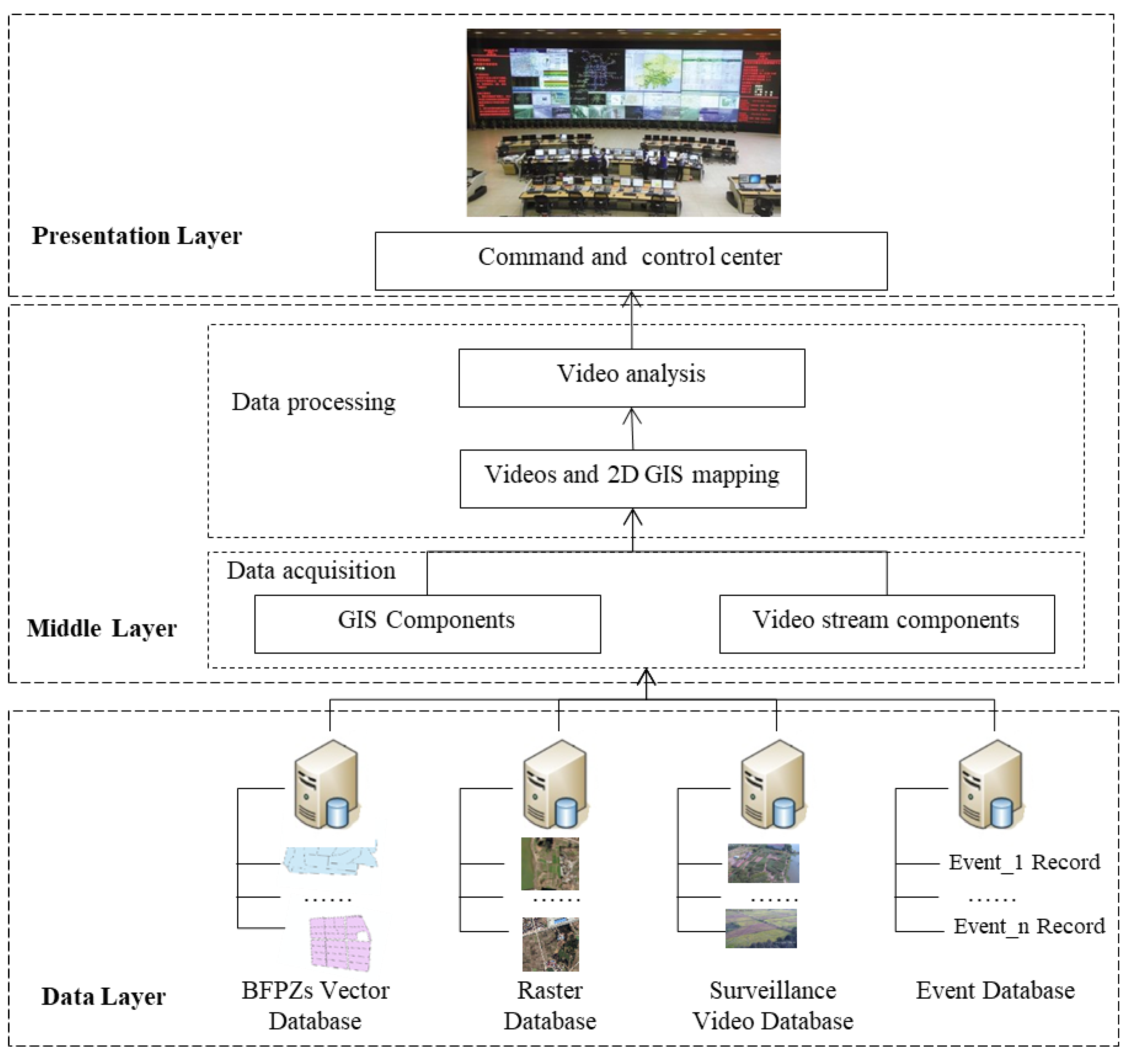
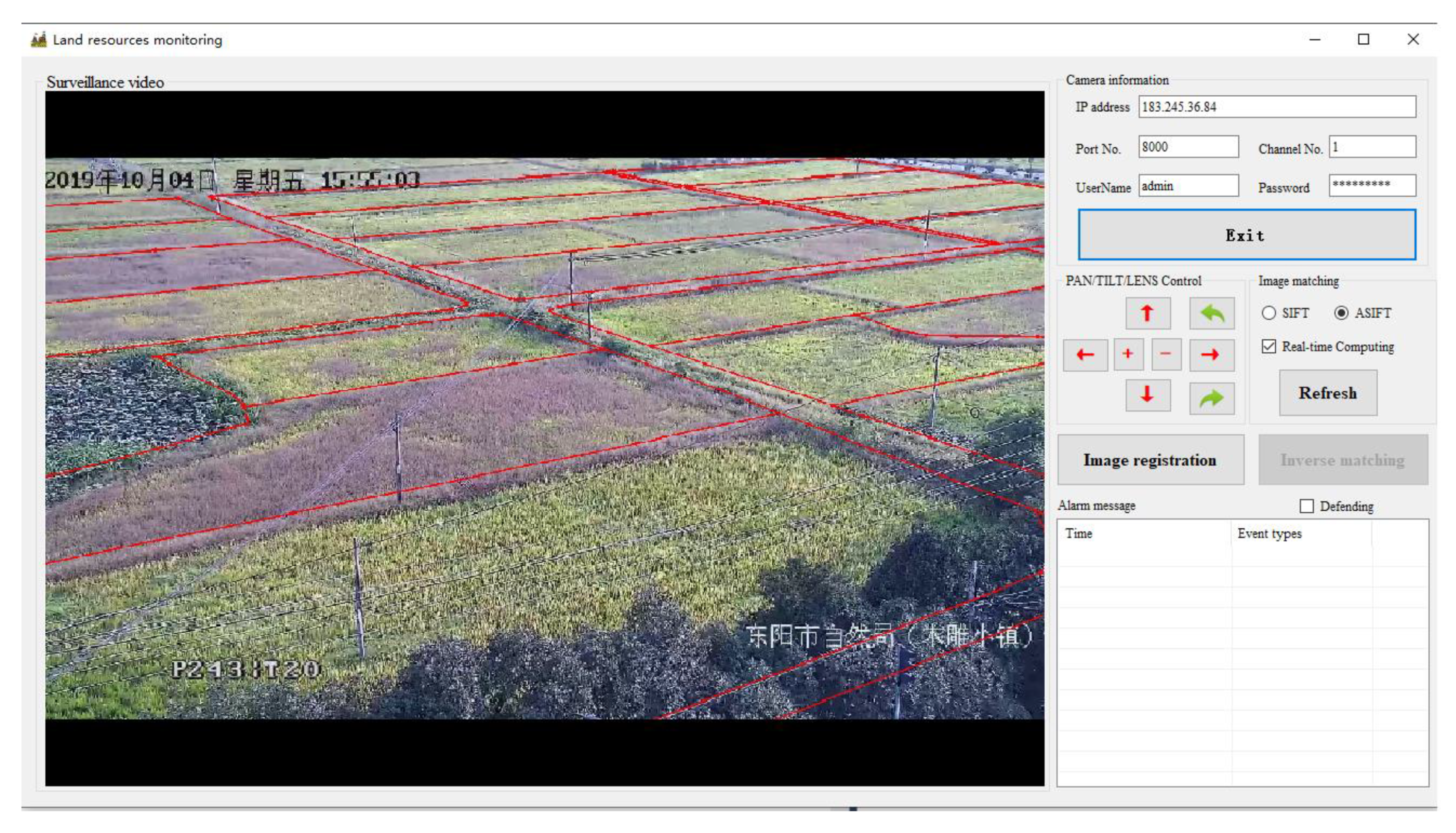
On the basis of the integration method of 2D vector BFPZs and real-time PTZ surveillance video, we design and implement a prototype of monitoring system. The system can collect, manage geospatial and video data, and perform overall display and analysis. Through video surveillance of cultivated land, supervisors can efficiently improve the supervision work. As shown in
Figure 6, the integration framework mainly contains three layers: presentation layer, middle layer, and data layer.
Data layer: The data layer is mainly used to store and manage geospatial and surveillance video data. In the proposed system, geospatial data contains BFPZs presented in 2D vector format and high-resolution ortho-images presented in raster format. The former is used to define ROI regions in real-time video, and the latter is used to establish the mapping relationship between geospatial space and image pixel coordinates.
Middle layer: The middle layer has functions of data acquisition, processing, and analysis. As geospatial data and video data are unstructured data, they are independent of each other. In this layer, GIS components are used for fetching geospatial data, and video stream components are used for reading real-time video data. 2D mapping between BFPZs and video images is the core component, and BFPZs data can be projected into real-time video to generate ROI area. For the specific area, video analysis can be performed.
Presentation layer: In the presentation layer, it provides interactive integration of 2D BFPZs data and surveillance video as well as real-time alert for command and control center.
The software structure of the cultivated land monitoring system consists of five parts: video retrieval, video control, image registration, image matching, and video analysis. Video retrieval is mainly used to load real-time video using HTTP protocol and display the current video frame. It can also visualize 2D BFPZs overlaid on video frames. Video control allows the user to pan, tilt, and zoom the PTZ camera and fetch the current, previous, or next video frame. Image registration provides an interactive tool for constructing the mapping matrix between 2D vector BFPZs and the preset video image by selecting correspondences between image space and geospatial space and solving the matrix parameters. Then, 2D vector BFPZs is projected into the preset video image. Image matching provides an automatic way that can use the multi-view image matching method ASIFT to construct the mapping between surveillance video images. Correspondences between video images can be detected and matched without human involvement. The projected 2D vector BFPZs in the preset video image can be mapped into real-time video images with different matching strategies. At last, 2D vector BFPZs polygons can be set as the defense area for intelligent video surveillance, which can efficiently extract useful information from the huge number of videos by automatically detecting, tracking, and recognizing objects and analyzing activities [
14].
6. Discussions
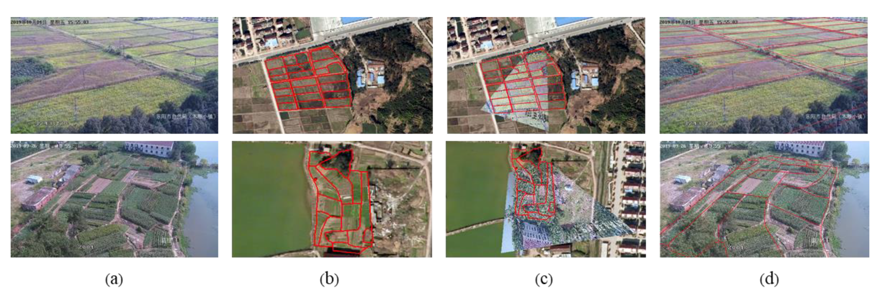
For a GIS-based video monitoring system, the prerequisite is to align the GIS data with video images. In order to accomplish this alignment, it is necessary to establish a mapping relationship between the video frame and GIS data. In this study, we propose a method to register 2D vector data of the protected cultivated land onto surveillance video images. Experimental results in cultivated land with relatively flat landscape suggest that the proposed method can accurately project 2D vector BFPZs onto real-time video frames and obtain meter-level positioning accuracy to meet the requirements of cultivated land monitoring.
Currently, there have been some studies on GIS-based video monitoring systems. The GeoScopeAVS system designed by Milosavljevic et al. [
16] integrated GIS and video surveillance for real-time retrieval of information about viewed geospatial objects. In their system, 3D GIS and camera views were aligned so that it is possible to extract the visualization of appropriate 3D virtual objects and place them over the video. However, this method may not be applicable to cultivated land, because 3D models of geographic features and accurate DEM of the area are essential. As we all know, people pay more attention to the modeling of urban environment, especially buildings, but the modeling of rural environment is largely ignored. Moreover, not all objects in the real world can be completely modelled, such as vehicles, people, trees, and street lights [
15]. Zhao et al. [
17] designed a GIS-based video monitoring system for forest insect defoliation and discoloration. Though 2D GIS and 3D GIS are simultaneously integrated in their system, it is not a real fusion because these data are geographically linked and separately displayed in their own window. Nonetheless, it is difficult for non-experts to interpret these data as they are not presented in the same layer. Milosavljevic et al. [
19] proposed a method to georeference video images, which relied on matching video frame coordinates of certain point features with their 3D geographic locations. Overall, the above-mentioned methods have one thing in common: all of them require internal and external parameters of the camera and high-precision 3D geospatial data, which are difficult to be accurately obtained for the case of cultivated land and cause failure. Zhang et al. [
18] presented a GIS-based prototype system for city safety management. They described a semi-automatic cross-mapping method based on 2D GIS and some constraints. However, the case of the PTZ camera was not considered in their system, which made them unsuitable for the monitoring of cultivated land. In comparison to them, our solution is more feasible in monitoring cultivated land. On the one hand, it is fast and easy to be implemented. Neither of the camera parameters and 3D model of objects are needed to integrate 2D GIS data and PTZ video images. Once a number of control points are identified from 2D GIS data and the selected reference video image, the alignment of 2D GIS data and PTZ video frames can be realized by automatic feature matching method. On the other hand, even non-experts and inexperienced persons can intuitively see the boundary of protected farmland from the surveillance video and identify destruction of cultivated land.
There are some factors that may influence the performance of our system: the selection of reference images as well as the amplitude and speed of video camera movement may change the overlap between images and have an impact on feature matching. If overlap between images is too small, it is difficult to obtain uniformly distributed corresponding features to estimate the geometric transformation matrix. In addition, a different matching strategy may affect the accuracy of video images and GIS data registration results. As described in
Section 5.2, a reasonable matching strategy can reduce the propagation of matching error. Comprehensively, it is better to choose Strategy-S instead of Strategy-A for the integration of 2D vector BFPZs and video images. One reason is the error propagation in Strategy-A, and the other reason is that it is difficult to determine the interval between adjacent images. The major shortcoming of Strategy-S is that the movement of the PTZ camera can be restricted. If the overlap between the preset frame and the current frame is too small, this strategy may fail. Furthermore, the proposed method is not suitable for areas of complex terrain, such as mountainous areas. In such areas, the geometric mapping relationship between video image plane and 2D GIS data cannot be simply modelled by homography transformation. It may fail in alignment video images with GIS data, and prevents the following application.
Based on the alignment results, we can easily identify the occurrence of farmland destruction by visually inspecting the image content covering the 2D vector area. In China, the conversion of permanent farmland in BFPZs to other uses is forbidden, while the use nature of non-permanent agricultural land can be changed, for example, to construction land, with the approval of relevant departments. Since the two kinds of farmland are very similar and indistinguishable in video images, it is necessary to label the protected area on the video image. The proposed method provides a solution to solve the problem of labelling basic farmland in PTZ videos. Polygons in the 2D GIS data define the boundary of protected cultivated land. If image content delimited by polygons is recognized as construction land, it can be recognized as an illegal change.
However, little effort has been made to automatically identify destruction of farmland or unauthorized change of farmland use from the video images. In current literature, there is almost no research and report on this issue. Moreover, this issue is a complicated problem that requires technologies in various subjects and fields, such as computer vision, intelligent video analysis, image processing, and data mining. In the future, we will try to improve the robustness of our system and further study on automatic detection of illegal farmland occupation from real-time PTZ video images delineated by 2D GIS vector data.


