Abstract
Mobile laser scanning (MLS) has been widely used in three-dimensional (3D) city modelling data collection, such as Google cars for Google Map/Earth. Building Information Modelling (BIM) has recently emerged and become prominent. 3D models of buildings are essential for BIM. Static laser scanning is usually used to generate 3D models for BIM, but this method is inefficient if a building is very large, or it has many turns and narrow corridors. This paper proposes using MLS for BIM 3D data collection. The positions and attitudes of the mobile laser scanner are important for the correct georeferencing of the 3D models. This paper proposes using three high-precision ultra-wide band (UWB) tags to determine the positions and attitudes of the mobile laser scanner. The accuracy of UWB-based MLS 3D models is assessed by comparing the coordinates of target points, as measured by static laser scanning and a total station survey.
1. Introduction
Mobile laser scanning (MLS) has been widely used in three-dimensional (3D) city modelling data collection, such as Google cars for Google Map/Earth. The point cloud created by mobile laser scanning is usually georeferenced by a Global Navigation Satellite System (GNSS) such as the United States (U.S.) Global Positioning System (GPS). Outdoor positioning and mobile laser scanning products with GNSS are mature, commercial mobile laser scanning system products that are available. Building Information Modelling (BIM) has recently emerged and become prominent for construction, management, and safety [1], and it will become compulsory for all buildings. 3D models of buildings are essential for BIM. Static laser scanning is usually used to generate 3D models for BIM, but this method is inefficient, in particular for very large buildings and buildings with many turns, rooms, and narrow corridors. With regard to static single-viewpoint data collection, excessive time and data redundancy are involved in achieving the integrity and coverage of data [2]. This paper proposes using MLS for BIM 3D data collection. An MLS system usually has two or more laser scanners arranged in an array to cover different angles of view. The use of known control points (in global/national coordinates systems) for georeferencing and registration of the point cloud in mobile laser scanning is difficult and impractical. Since the use of artificial markers as control points is time-consuming, geometric 3D keypoints of salient features can be used to perform the automatic coarse registration of point clouds [3]. The trajectory of an outdoor mobile laser scanner can be determined by the integration of GNSS and the Inertial Navigation System (INS)/Inertial Measurement Unit (IMU) [2]. INS/IMU is used to estimate positions when GNSS navigation cannot provide fixed solutions due to insufficient numbers of observing GNSS satellites, but INS/IMU measurement drifting limits the accuracy and robustness of INS/IMU (i.e., positioning errors increase as the GNSS signal outage time increases) [4,5]. Accurate positions and attitudes of the mobile laser scanner are very important for the correct georeferencing of the 3D models containing BIM geometry; the accuracy of the point cloud should be to the decimetre or better.
GNSS has been widely used in positioning and outdoor navigation. With carrier-phase GNSS positioning, decimetre or centimetre positioning accuracy can be achieved. However, the GNSS signal is generally very weak and noisy inside buildings, and impossible to receive deep inside buildings. Recently, indoor positioning has attracted the attention of researchers, governments, and other users, as it has a wide range of potential applications such as location-based services, safety-of-life applications, security and safety applications, and the Internet of Things (IoT). Currently, Wireless Local Area Network (WLAN/WiFi), Bluetooth, Radio Frequency Identification (RFID), ZigBee, and ultra-wide band (UWB) are the main sensors that are used for indoor positioning (not only for presence/proximity). The positioning accuracy and some key features of the sensors are summarised in Table 1 [6,7,8,9,10,11]. These types of sensors can be used alone or integrated with, for example, RFID, GNSS, and dead reckoning (DR) for ubiquitous positioning in pedestrian navigation, as proposed in [12]. Moreover, an outdoor mobile sensing system based on GPS/IMU, cameras, laser scanners, and video cameras (named MoSES) can be modified to work promisingly in difficult tunnel environments [13], a laser gyroscope (IMAR iNAV-RQH) and seven high sensitivity infrared spectrum JAITM cameras with auxiliary Light-Emitting Diode (LED) lighting are adopted, and the Kalman filter is refined.

Table 1.
Summary of key features of indoor positioning sensors. GNSS: Global Navigation Satellite System; RFID: Radio Frequency Identification; UWB: ultra-wide band.
Indoor GPS (i.e., pseudolite), UWB, and WLAN for user localisation in indoor construction environments are evaluated in [14], which found the position uncertainties to be 1–2 cm, 0–50 cm, and 1.5–2 m, respectively. However, indoor GPS is very expensive, and its measurements need line of sight, which makes it less practical in difficult indoor construction environments. In addition to the above popular indoor positioning sensors, the 2.4 GHz phase offset technique [15], modulated magnetic signals [16], 24-GHz radar [17], light detection and ranging (LiDAR) [18], and foot-mounted IMU [19] are proposed for the purpose. These systems participated in the Microsoft Indoor Localization Competition [20] in 2017, which judged that only LiDAR and UWB-based systems could achieve better than metre-level positioning accuracy; the LiDAR-based system can achieve centimetre-level positioning accuracy, and the UWB-based system can achieve decimetre-level positioning accuracy [20]. Although LiDAR-based technology is extremely accurate, the cost, size, and power consumption of LiDAR sensors prevent this technology from becoming a mainstream indoor positioning solution [20].
As described above, UWB-based systems are accurate and cost efficient compared with the other state-of-the-art indoor positioning sensors. Moreover, “UWB systems have emerged as one of the leading technologies for indoor positioning and have been used in many more applications than before” [6]. This paper carries out basic research using three high-precision ultra-wide band (UWB) tags to determine the positions and attitudes of the laser scanner for mobile laser scanning, and hence georeferencing for point clouds. With the big black-and-white photogrammetric targets, the accuracy of the 3D models generated by the UWB-based mobile laser scanning system is assessed by comparing the coordinates of the targets determined by UWB-based mobile laser scanning with the coordinates of the targets that are determined by the total station survey. Moreover, the coordinates of the targets determined by static laser scanning are compared with the coordinates of the targets determined by a total station survey. Users may refer to the determined achievable accuracies of the proposed mobile laser scanning method and the conventional static laser scanning method for selecting a scanning method to be used in their projects/applications. In practical considerations, the UWB infrastructure can support not only the proposed mobile laser scanning in all of the phases of BIM, it can also support the indoor positioning and tracking of humans, machines, and other objects.
2. Background
This section briefly introduces mobile laser scanning and the UWB indoor positioning technology and its measurements.
2.1. Mobile Laser Scanning
Mobile laser scanning (MLS) can take measurements of large areas continuously and efficiently. For general MLS platforms, the laser scanner is rotated about one axis, and the 3D environment can be captured by a two-dimensional (2D) laser scanner. The basic principle of mobile laser scanning rests mainly on the determination of time-stamped trajectories of a vehicle mounted with a 2D laser scanner, which is also the basic requirement for achieving mobile laser scanning. In outdoor MLS, the trajectory can be computed by the combination of high-precision GNSS and IMU, which are also mounted on the vehicle. Then, the georeferencing of the laser range measurements acquired by the 2D laser scanner is achieved through the trajectory [21]. However, GNSS is not available in construction, or other indoor environments. Therefore, indoor positioning devices with high accuracy and precision are required for indoor MLS. Whether using indoor or outdoor mobile laser scanning, the quality of the final point cloud is mainly determined by two factors: (1) the accuracy of the laser scanner itself; and (2) the accuracy of the external positioning systems [21]. More information about MLS can be found in [22,23,24]. Simultaneous Localisation and Mapping (SLAM) is a technique that can be used to generate the point cloud in indoor environments. The point clouds of five selected commercial systems, Matterport [25], Zebedee [26], NavVis [27], Leica Pegasus: Backpack [28], and Kaarta Stencil [29], and three research prototypes, Aalto VILMA [30,31], FGI Slammer [2], and the Würzburg backpack [32], are compared with survey-grade terrestrial laser scanning (TLS) point clouds obtained with Leica and Faro scanners (i.e., the “truth”) in [33], where an agreement of 0.2 m–2 m was found. SLAM-based methods do not need control points (i.e., points with known coordinates) in point cloud generation; however, these methods will need control points for georeferencing the points in point clouds at a later stage if the 3D models are required to tie in with national coordinates systems, which is always the case when point clouds are used for BIM and GIS applications. If the positions and attitudes of the laser scanner in mobile scanning are known, the georeferencing of points in point clouds may be done in real-time laser scanning.
2.2. UWB for Indoor Positioning
The UWB-based indoor positioning system has received increasing interest among researchers in recent years. Precise positioning using UWB technology has been involved in many applications, mainly in indoor environments. Examples include tracking assets in warehouses, analysing the field positions of soccer players, and improving productivity in assembly lines [34].
The Federal Communications Commission defines UWB as a radio frequency (RF) signal occupying a portion of the frequency spectrum that is greater than 20% of the centre carrier frequency, or that has a bandwidth greater than 500 MHz [35]. Compared with traditional wireless positioning techniques, UWB transmits information based on a narrow pulse (nanosecond-level), but not the carrier phase, over a wide portion of the frequency spectrum. UWB can be used for positioning by using the time difference of arrival (TDOA) and angle of arrival (AOA) of the RF signals. For TDOA, this approach is to measure the differences between times of arrival (TOA) from every receiver, so it does not need time synchronisation among receivers, but transmitters must be synchronised. AOA is based on the direction from which the received signal arrives; thus, it does not need time synchronisation, but it increases the cost for antenna arrays. More information about UWB signals and measurements can be found in [36,37].
The short pulse property of UWB has many advantages as an indoor positioning sensor. First, the multipath effect on a UWB-based system is much smaller than on any other positioning techniques, since it uses very short pulses with a duration of less than a few nanoseconds, which makes it possible to filter out the reflected signals. Second, it has low power consumption, because of the use of an ultra-short pulse. Third, its strong penetrating power allows the UWB signals to penetrate several layers of wall easily. Moreover, the positioning accuracy of UWB is very high, as shown in Table 1: it can achieve decimetre-level or even centimetre-level positioning accuracy. The cccuracy assessment of UWB in construction-related scenarios such as signal blockage, multipath effect, and metal surface can be found in [38], and the deterioration of UWB positioning during construction can be found in [39].
Some manufacturers developed UWB systems using TDOA only. We tested using only TDOA and only AOA with our Ubisense UWB 7000 IP system for indoor positioning, and found [40] that TDOA is good for long-distance measurements, and AOA is good for close measurements. Specifically, we found that TDOA is good for distance measurements longer than about 17 m with our UWB system. In many construction sites and buildings, such as office buildings and apartments, AOA measurements are important for reliable, accurate, and continuous indoor positioning. Moreover, AOA measurements suffer less interference from reflected signals (i.e. multipath). Therefore, UWB systems with both TDOA and AOA measurements are more robust for positioning in difficult indoor environments. UWB systems with both TDOA and AOA are not much more expensive than TDOA-only systems, but the loss in accuracy, robustness, and reliability are much higher than the cost savings.
3. Proposed Method—UWB-Based Indoor Mobile Laser Scanning
As described above, UWB is a precise and accurate indoor positioning technology that is suitable for difficult and complicated construction and indoor environments. A UWB-based mobile laser scanning system is proposed in this paper. The position (easting (E), northing (N), height (H) in a national/global grid coordinates system) and attitude (yaw, pitch, roll) of the mobile laser scanner are determined by three UWB tags. A Ubisense UWB 7000 IP sensors and Leica HDS 7000 laser scanner are used in our algorithm validation. Four UWB tags were installed on the top four corners of the laser scanner, as shown in Figure 1. Only three UWB tags are needed in our algorithm; one UWB tag was found out of service after the trial. The proposed UWB-based position and attitude determination algorithm is presented as follows.
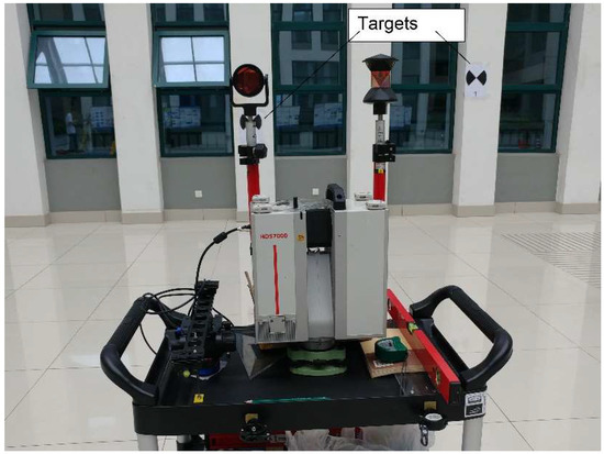
Figure 1.
The UWB-based mobile laser scanning platform.
UWB TDOA and AOA measurements are used in our algorithm to estimate the positioning and attitude parameters of the three UWB tags on the laser scanner. The principle of TDOA is illustrated in Figure 2, which shows UWB sensors 1 and 2 and a UWB tag/transmitter. The coordinates (E, N, H) of the UWB sensors are known by a pre-survey with the Leica TS30 total station; time synchronisation among UWB sensors connected by high-quality shielded Ethernet cables is done by calibration. A TDOA measurement is calculated by subtracting the TOA measurement of a sensor and tag pair from the TOA measurement of the reference sensor and tag pair. The mathematical model of a TDOA measurement is shown as follows.
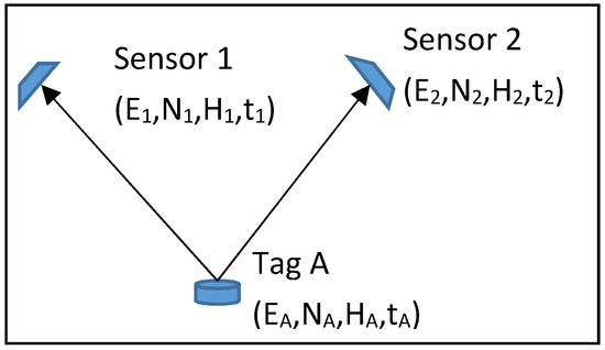
Figure 2.
Concept of TDOA measurement.
With reference to Figure 2, the TOA measurement between Sensor 1 and Tag A (TOAA1) is written as:
where c denotes the speed of light, and tA and t1 denote the time at Tag A and Sensor 1, respectively. The TOA measurement between Sensor 2 and Tag A (TOAA2) is written as:
where tA and t2 denote the time at Tag A and Sensor 2, respectively. Then, the TDOA measurement to Sensors 1 and 2 at Tag A is:
When there are a number of UWB sensors, one sensor acts as the reference sensor. Sensor 1 is the reference sensor. Time synchronisation between the tag and the sensors is not necessary, because any time offsets between them are eliminated in Equation (3). The unknown coordinates of tag A are solved by least squares or other numerical methods, with the observation model as:
AOA measurements (αA1–3) and the horizontal position solution by triangulation [19] are shown in Figure 3.
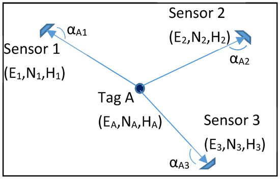
Figure 3.
AOA measurements and triangulation.
Physical offsets between the UWB tags and the laser scanner centre are measured by precise total station intersection from two known stations, the accuracy of the surveyed offsets being better than a millimetre. The offsets are used to calculate the mobile laser scanner centre from UWB-determined tag positions and attitude angles in the local coordinates system, as shown in Figure 4. In Figure 4, X points to the trajectory forward direction, Y is the laser scanning spinning direction that is horizontally perpendicular to X, and Z is the up direction to complete the Cartesian coordinates system of the laser scanning body reference frame. The direction from UWB Tag A to Tag B is aligned with the trajectory forward direction X, with any misalignment being calibrated with the known travelling direction beforehand. Moreover, the direction from UWB Tag A to Tag C is aligned with the laser scanning spinning direction Y. Therefore, the attitude angles (yaw, pitch, roll) are calculated by:
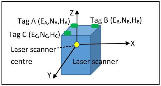
Figure 4.
Locations of the UWB tags on the laser scanner and the body reference frame of the laser scanner.
The laser scanning points are then tied to the local coordinates system by transformation, the translations being determined from the known offsets between the UWB tags and the laser scanner centre, and the rotation matrices being obtained from the attitude angles in Equations (5)–(7). Putting the attitude angles (yaw, pitch, roll) calculated by Equations (5)–(7) into rotation matrices in the X, Y, and Z axes of the body reference frame, the rotation matrices are formed as:
The combined rotation matrix =
More details regarding attitude determination and coordinates transformation can be found in [3,4,41,42,43].
4. Test of the Proposed Method
The atrium of the Sir Peter Mansfield Building at the University of Nottingham in Ningbo, China was selected as the test site, because we have UWB sensors installed in the building. A closed traverse was carried out; the traverse started at a control station U51 near the north entrance of the building, travelled through the atrium, and finished at another control station U54 near the south entrance of the building. The reference system of the control stations is in the Universal Transverse Mercator (UTM) system. A Leica Geosystems TS30 total station and GPR1 standard prism were used in the traversing, the instrumental angular accuracy was 0.5″, and the distance measurement accuracy was 0.6 mm + 1 ppm (in the precise distance measuring mode) according to the TS30 specifications. The closed traverse had eight stations (including the starting and finishing control stations) and the total length was 154.224 m. The angular misclosure and the linear misclosure of the traverse were 9.06″ and 1.59 cm, respectively, and the fractional linear misclosure was 1 in 9700. Levelling was carried out to determine the normal heights of the traversing stations, a Leica Geosystems Sprinter 150 electronic level was used in the levelling, and the instrumental accuracy was 1.5 mm per 1 km, according to the manufacturer’s specifications. The loop levelling had seven instrument points, it started and finished at the control station U51 (with known normal height). The levelling misclosure was 1 mm. In order to minimise the errors in traverse and levelling propagating into the coordinates of the UWB sensors and photogrammetric targets, the known coordinates of the UWB sensors and photogrammetric targets were determined using the total station intersection from two traversing stations A1 and C5 in the atrium area of the building. Therefore, the positions of the UWB tags that were to be computed from UWB measurements with respect to the UWB sensors were relative to the two traversing stations only. Positions and attitudes of the mobile laser scanner in the proposed method were estimated from the positions of the UWB tags, and thus were relative to the two traversing stations as well. Moreover, the positions of the photogrammetric targets to be used as the “truth” were also relative to the two intersection traversing stations only. Static laser scanning of the photogrammetric targets was carried out at the traversing station A1. A Leica Geosystems GPLE3N precise invar levelling rod was put to one side of the target areas (the west side of the atrium), and used to estimate the intersection accuracy; two points on the levelling rod were observed simultaneously at the two traversing stations A1 and C5. The relative accuracy of 0.0069 cm was obtained by comparing the computed length (by intersection; 0.899931 m) and true length (0.9 m) of the two points on the invar rod. Besides, the lever-arm offsets between the UWB tags and the laser scanner centre were also measured by the total station intersection. The MicroSurvey Star*Net was used to calculate the traverse and intersection data.
The accuracy performance of the proposed UWB-based mobile laser scanning system was assessed by running a stop-and-go laser scan between three known points (which were not used for the performance assessment of the proposed method) in the atrium of the building. The locations of the three known points, C4, A0, and C1, and the six UWB sensors, numbered 1–6, in the atrium area are shown in Figure 5. The sensors were installed at about 9 m above the ground, in consideration of signal coverage and economy. Ten photogrammetric targets were used to assess the laser scanning accuracy; two such targets are shown in Figure 1. In the experiment, the positions of the UWB tags on the laser scanner were measured when the mobile platform (see Figure 1) stopped at the known points C4, A0, and C1 (with a ranging rod pointed at the known point on the ground, and the secondary ranging rod pointed at the secondary control point). This rigorous stop-and-go test allowed us to get the UWB positioning and mobile laser scanning accuracies accurately without the effects of the dynamic of the moving platform, the residual in UWB time synchronisation, and the accuracy of visiting reference positions at a particular time in the reference time system.
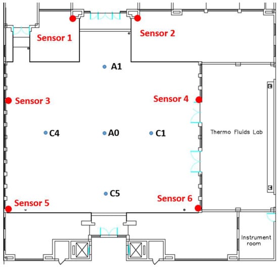
Figure 5.
Locations of the known points and UWB sensors at the test site (scale: the horizontal distance between A0 and A1 is about 11 m).
In addition to the mobile laser scanning, a static laser scanning survey was carried out. The centres of the photogrammetric targets obtained by both mobile and static laser scanning were compared with the “truth” that was determined by the total station intersection. This comparison result could let users select the proposed mobile scanning method or the conventional static scanning method in projects/applications. The accuracy assessment metrics are described as follows.
Root mean square error (RMSE) was used to assess the accuracy in each component of a 3D coordinate system:
where n is the number of samples, i is the samples from 1 to n, Xi is the value of sample i, and is the “truth” value. X is the northing, easting, or height component in this assessment.
Distance root mean square error (DRMSE) measures the accuracy in the horizontal plane (2D):
where X and Y represent the perpendicular components of horizontal coordinates. X is the easting and Y is the northing in this assessment.
Mean radial spherical error (MRSE) measures the accuracy in 3D space:
where X, Y, and Z represent the perpendicular components of Cartesian coordinates. X is the easting, Y is the northing, and Z is the height in this assessment.
4.1. Results
The statistical results obtained from Equations (12)–(14) for the UWB-determined tag positions against the “truth” tag positions determined by total station intersection are presented in Table 2. Further, the statistical results of the photogrammetric targets obtained by static and mobile laser scanning against the total station intersection “truth” are given in Table 3 and Table 4, respectively. Table 5 shows the statistical results of the mobile laser scanning against the total station intersection “truth” on the photogrammetric targets at less than 10 m from the laser scanner.
Table 2.
Statistical results of the tag positions determined by the UWB positioning against the “truth” obtained from the total station intersection. RMSE: root mean square error; DRMSE: distance root mean square error; MRSE: mean radial spherical error; 3D: three-dimensional.
Table 3.
Statistical results of the photogrammetric targets determined by the static laser scanning against the “truth” obtained from the total station intersection.
Table 4.
Statistical results of the photogrammetric targets determined by the mobile laser scanning against the “truth” obtained from the total station intersection.
Table 5.
Statistical results of the photogrammetric targets, which are less than 10 m from the laser scanning, determined by the mobile laser scanning against the “truth” obtained from the total station intersection.
4.2. Discussion
As shown in Table 2, the UWB system can achieve centimetre positioning accuracy in the horizontal plane, but decimetre accuracy in the height. The UWB height error is about twice the horizontal error, because all of the UWB sensors are above the ground, and no geometric error cancellation from below the horizontal plane is possible. This geometric problem is similar to GNSS/GPS, which permits only poor height determination, owing to the absence of satellite signals from below the Earth’s surface. The poor UWB height determination makes the UWB system capable of achieving only decimetre positioning accuracy in 3D space (see the MRSE in Table 2).
As the results in Table 3 show, static laser scanning can achieve millimetre accuracy. This accuracy conforms with the specifications of the selected scanning resolution given by the laser scanner manufacturer.
The easting and height accuracies of UWB-based mobile laser scanning are in centimetres and decimetres, respectively, as shown in Table 4. However, the northing accuracy is in metres. This is because the mobile laser scanning platform was moved along the north–south axis in the trial (the scanning direction was in the east–west plane) and the photogrammetric targets were stuck on the walls perpendicular to the north–south axis. Therefore, the errors in the UWB-determined attitude angles affected mainly the northing accuracy in this experimental design. Since the distances between the UWB tags on the laser scanner are short (i.e., Tag A to Tag B is about 26 cm, and Tag A to Tag C is about 13 cm), small positioning errors at tags in such short baselines lead to significant errors in the estimated attitude angles. If the distance from the laser scanner to the scanning object increases, the attitude errors will ‘amplify’ the errors in the coordinates of the point cloud. As the size of the top surface of laser scanners is usually small (not more than a few decimetres by a few decimetres), a possible solution to reduce the attitude errors in short baselines is to put two rigid arms perpendicular to each other on top of the laser scanner in order to increase the distances between the UWB tags. However, this may introduce problems in practice, such as the increased weight and size of the equipment, and operational difficulties in small areas and narrow corridors. Moreover, UWB error mitigation methods must be developed in order to reduce the effect of the multipath and non-line-of-sight signals (i.e., no direct signals, but only reflected signals received).
As discussed above, the distance from the laser scanner to the scanning object does affect the accuracy of the point cloud in the proposed UWB-based mobile laser scanning system. When excluding the photogrammetric targets with distances longer than 10 m from the mobile laser scanner, the statistical results in Table 5 show that decimetre accuracy can be achieved. This decimetre accuracy is comparable to the accuracy (i.e., decimetre level) of the automatic point cloud coarse registration that was proposed in [3]. Besides, this short-range (>10 m) mobile laser scanning accuracy is close to the positional accuracy (0.2 m at 95% level) obtained from the outdoor GPS and IMU-based mobile laser scanning in [22]. An application of this short-range, UWB-based mobile laser scanning is as-built BIM modelling.
5. Conclusions and Further Research
Outdoor mobile laser scanning systems with georeferencing by Global Navigation Satellite System (GNSS)/Global Positioning System (GPS), Inertial Navigation System (INS)/Inertial Measurement Unit (IMU), dead reckoning (DR), etc., are well-developed, commonly available commercial products. Google EarthTM is an example of products in the area of mobile mapping systems (including mobile laser scanning). Building Information Modelling (BIM) has recently emerged, and has become very prominent. 3D models of buildings are essential for BIM. Conventional static laser scanning is not efficient, especially for scanning in very large buildings and buildings with many turns, rooms, and narrow corridors. The state-of-the-art indoor positioning sensors/technologies are reviewed in this paper. The ultra-wide band (UWB) indoor positioning system is the best in terms of precision in distance and angular measurements, positioning accuracy, and size. The UWB infrastructure can be used for indoor positioning and tracking of humans, machines, and other objects. Indoor SLAM systems (which usually have two laser scanners and an IMU) may be modified to use UWB for positioning of the SLAM platforms, but the authors do not think this will happen, because substantial modifications in hardware and software are needed, which may completely change the SLAM concept.
A new UWB-based indoor mobile laser scanning method is proposed in this paper. The UWB positioning system is used to determine the position and attitude angles (yaw, pitch, roll) of the mobile laser scanner on its scanning trajectory. In other words, the UWB system is used for georeferencing of the point cloud obtained in mobile laser scanning. The proposed system has been tested rigorously in the atrium of the Sir Peter Mansfield Building at the University of Nottingham Ningbo China. The UWB positioning accuracy and the proposed mobile laser scanning accuracy (i.e., the accuracy of the coordinates of the point cloud) are obtained by comparing the estimated coordinates of target/tag points with the “truth” coordinates that are determined by high-accuracy total station intersection.
The UWB system can achieve centimetre positioning accuracy on the horizontal plane, but decimetre accuracy in height. UWB positioning errors have been discussed, and possibilities for further research for UWB multipath mitigation and solutions for non-line-of-sight problems have been identified. It is found that the UWB positioning errors of the close UWB tags on the laser scanner induced large errors in the estimated attitude angles. Therefore, the accuracy of the coordinates of the point cloud obtained by the proposed UWB-based georeferencing system is affected by the distance between the scanning object and the laser scanner. Nevertheless, it is proven in this research that the proposed UWB-based indoor mobile laser scanning can achieve decimetre accuracy when the scanning object is less than 10 m from the laser scanner. Such accuracy limits the use of the mobile laser scanning point cloud; therefore, the proposed system in short-range (less than 10 m) scanning can be used, among other applications, for point cloud coarse registration and as-built BIM modelling. A method of installing two rigid arms (perpendicular to each other) on top of a laser scanner has been proposed to increase the distances between the UWB tags in order to reduce the impact of UWB positioning errors on the estimated attitude angles. Further research into this method is needed, although it may impair the practical efficiency of the mobile system.
Acknowledgments
The authors would like to thank the reviewers for their in-depth reviews and helpful suggestions, which have greatly contributed to improving this paper. The work presented in this paper is funded by the Zhejiang Natural Science Foundation (ZJNSF) General Programme grant LY17D040001.
Author Contributions
L.L. provided the initial idea and conception; L.L., Y.Q., J.W. and N.Z. conceived, designed and performed the experiments; L.L., C.W., N.Q., and F.J. helped with the analysis of the data. L.L. wrote the paper; Y.Q., N.Z. and C.W. helped with the writing. All authors reviewed the manuscript.
Conflicts of Interest
The authors declare no conflict of interest. The founding sponsors had no role in the design of the study; in the collection, analyses, or interpretation of data; in the writing of the manuscript, and in the decision to publish the results.
References
- Zhang, S.; Teizer, J.; Lee, J.K.; Eastman, C.M.; Venugopal, M. Building Information Modeling (BIM) and Safety: Automatic Safety Checking of Construction Models and Schedules. Autom. Constr. 2013, 29, 183–195. [Google Scholar] [CrossRef]
- Kaijaluoto, R.; Kukko, A.; Hyyppä, J. Precise Indoor Localization for Mobile Laser Scanner. ISPRS Int. Arch. Photogramm. Remote Sens. Spat. Inf. Sci. 2015, 1–6. [Google Scholar] [CrossRef]
- Bueno, M.; González-Jorge, H.; Martínez-Sánchez, J.; Lorenzo, H. Automatic point cloud coarse registration using geometric keypoint descriptors for indoor scenes. Autom. Constr. 2017, 81, 134–148. [Google Scholar] [CrossRef]
- Rogers, R.M. Applied Mathematics in Integrated Navigation Systems, 3rd ed.; American Institute of Aeronautics and Astronautics: Reston, VA, USA, 2007; pp. 103–113. [Google Scholar] [CrossRef]
- Grewal, M.S.; Andrews, A.P.; Bartone, C.G. Global Navigation Satellite Systems, Inertial Navigation, and Integration, 3rd ed.; John Wiley & Sons, Inc.: Hoboken, NJ, USA, 2013; ISBN 978-1-118-44700-0. [Google Scholar]
- Alarifi, A.; Al-Salman, A.; Alsaleh, M.; Alnafessah, A.; Al-Hadhrami, S.; Al-Ammar, M.; Al-Khalifa, H. Ultra Wideband Indoor Positioning Technologies: Analysis and Recent Advances. Sensors 2016, 16, 707. [Google Scholar] [CrossRef] [PubMed]
- Guo, H.; Fang, S.; Yu, M. A new indoor positioning method based on Zigbee system. In Proceedings of the 29th International Technical Meeting of the Satellite Division of the Institute of Navigation (ION GNSS+ 2016), Portland, OR, USA, 12–16 September 2016; pp. 816–821. [Google Scholar]
- Luoh, L. ZigBee-based intelligent indoor positioning system soft computing. Soft Comput. 2014, 18, 443–456. [Google Scholar] [CrossRef]
- Razavi, S.N.; Moselhi, O. GPS-less indoor construction location sensing. Autom. Constr. 2012, 28, 128–136. [Google Scholar] [CrossRef]
- Woo, S.; Jeong, S.; Mok, E.; Xia, L.; Choi, C.; Pyeon, M.; Heo, J. Application of WiFi-based indoor positioning system for labor tracking at construction sites: A case study in Guangzhou MTR. Autom. Constr. 2011, 3–13. [Google Scholar] [CrossRef]
- Zhao, R.; Zhong, B.; Zhu, Z.L.; Ma, L.; Yao, J.F. Overview of Indoor Localization Techniques and Applications. Electr. Sci. Technol. 2014, 27, 154–157. [Google Scholar]
- Retscher, G.; Fu, Q. Integration of RFID, GNSS and DR for Ubiquitous Positioning in Pedestrian Navigation. J. Glob. Position. Syst. 2007, 6, 56–64. [Google Scholar] [CrossRef][Green Version]
- Núñez-Andrés, M.A.; Buill, F.; Delgado-Medina, S.; Plancho-Milian, C. The use of geomatic techniques to improve the management of metro infrastructure. Surv. Rev. 2017. [Google Scholar] [CrossRef]
- Khoury, H.M.; Kamat, V.R. Evaluation of position tracking technologies for user localization in indoor construction environments. Autom. Constr. 2009, 18, 444–457. [Google Scholar] [CrossRef]
- Reimann, R.; Bestmann, A.; Ernst, M. Locating Technology for AAL Applications with Direction Finding and Distance Measurement by Narrow Bandwidth Phase Analysis. In Evaluating AAL Systems through Competitive Benchmarking, EvAAL 2012, Communications in Computer and Information Science; Chessa, S., Knauth, S., Eds.; Springer: Berlin/Heidelberg, Germany, 2013; Volume 362, pp. 52–62. [Google Scholar]
- Pirkl, G.; Lukowicz, P. Robust, low cost indoor positioning using magnetic resonant coupling. In Proceedings of the 2012 Association for Computing Machinery Conference Ubiquitous Computing/International Conference on Ubiquitous Computing (Ubicomp-2012), Pittsburgh, PA, USA, 5–8 September 2012; pp. 431–440. [Google Scholar]
- Dobrev, Y.; Reustle, C.; Pavlenko, T.; Cordes, F.; Vossiek, M. Mobile robot 6d pose estimation using a wireless localization network. In Proceedings of the 2016 IEEE MTT-S International Conference Microwaves for Intelligent Mobility (ICMIM), San Diego, CA, USA, 19–20 May 2016; pp. 1–4. [Google Scholar]
- RealEarth. Available online: www.realearth.us (accessed on 16 March 2018).
- Ju, H.; Park, S.Y.; Park, C.G. Pedestrian Dead Reckoning System Considering Actual Condition of the Foot-Mounted IMU. Microsoft Indoor Localization Competition, Technical Report. Available online: https://www.microsoft.com/en-us/research/wp-content/uploads/2016/11/Ju_SoyoungPark.pdf (accessed on 16 March 2018).
- Lymberopoulos, D.; Liu, J. The Microsoft Indoor Localization Competition: Experiences and Lessons Learned. IEEE Signal Process. Mag. 2017, 34, 125–140. [Google Scholar] [CrossRef]
- Elseberg, J.; Borrmann, D.; Nüchter, A. Algorithmic solutions for computing precise maximum likelihood 3D point clouds from mobile laser scanning platforms. Remote Sens. 2013, 5, 5871–5906. [Google Scholar] [CrossRef]
- Barber, D.; Mills, J.; Smith-Voysey, S. Geometric validation of a ground-based mobile laser scanning system. ISPRS J. Photogramm. Remote Sens. 2008, 63, 128–141. [Google Scholar] [CrossRef]
- Puente, I.; González-Jorge, H.; Martínez-Sánchez, J.; Arias, P. Review of mobile mapping and surveying technologies. Measurement 2013, 46, 2127–2145. [Google Scholar] [CrossRef]
- Lehtomaki, M.; Jaakkola, A.; Hyyppa, J.; Lampinen, J.; Kaartinen, H.; Kukko, A.; Puttonen, E.; Hyyppa, H. Object Classification and Recognition from Mobile Laser Scanning Point Clouds in a Road Environment. IEEE Trans. Geosci. Remote Sens. 2016, 54, 1226–1239. [Google Scholar] [CrossRef]
- Immersive 3D Spaces for Real-World Applications, Matterport. Available online: https://matterport.com/ (accessed on 16 March 2018).
- Bosse, M.; Zlot, R.; Flick, P. Zebedee: Design of a Spring-Mounted 3-D Range Sensor with Application to Mobile Mapping. IEEE Trans. Robot. 2012, 28, 1104–1119. [Google Scholar] [CrossRef]
- Navvis. Digitizing Indoors—NavVis. Available online: http://www.navvis.com (accessed on 16 March 2018).
- Leica Geosystems. Leica Pegasus: Backpack. Available online: http://www.leica-geosystems.com (accessed on 16 March 2018).
- Kaarta. Stencil. Available online: http://www.kaarta.com (accessed on 16 March 2018).
- Lehtola, V.V.; Virtanen, J.P.; Vaaja, M.T.; Hyyppä, H.; Nüchter, A. Localization of a mobile laser scanner via dimensional reduction. ISPRS J. Photogramm. Remote Sens. 2016, 121, 48–59. [Google Scholar] [CrossRef]
- Lehtola, V.V.; Virtanen, J.P.; Kukko, A.; Kaartinen, H.; Hyyppä, H. Localization of mobile laser scanner using classical mechanics. ISPRS J. Photogramm. Remote Sens. 2015, 99, 25–29. [Google Scholar] [CrossRef]
- Lauterbach, H.; Borrmann, D.; Heß, R.; Eck, D.; Schilling, K.; Nüchter, A. Evaluation of a Backpack-Mounted 3D Mobile Scanning System. Remote Sens. 2015, 7, 13753–13781. [Google Scholar] [CrossRef]
- Lehtola, V.V.; Kaartinen, H.; Nüchter, A.; Kaijaluoto, R.; Kukko, A.; Litkey, P.; Honkavaara, E.; Rosnell, T.; Vaaja, M.T.; Virtanen, J.-P.; et al. Comparison of the Selected State-Of-The-Art 3D Indoor Scanning and Point Cloud Generation Methods. Remote Sens. 2017, 9, 796. [Google Scholar] [CrossRef]
- Tanigawa, M.; Hol, J.D.; Dijkstra, F.; Luinge, H.; Slycke, P. Augmentation of low-cost GPS/MEMS INS with UWB positioning system for seamless outdoor/indoor positioning. In Proceedings of the 21st International Technical Meeting of the Satellite Division of the Institute of Navigation (ION GNSS 2008), Savannah, Georgia, 16–19 September 2008; pp. 1117–1124. [Google Scholar]
- Federal Communications Commission. First Report and Order 02-48; Federal Communications Commission: Washington, DC, USA, February 2002. Available online: https://transition.fcc.gov/Bureaus/Engineering_Technology/Orders/2002/fcc02048.pdf (accessed on 16 April 2018).
- Gezici, S.; Poor, H.V. Position estimation via ultra-wide-band signals. Proc. IEEE 2009, 97, 386–403. [Google Scholar] [CrossRef]
- Sahinoglu, Z.; Gezici, S.; Guvenc, I. Ultra-wideband Positioning Systems: Theoretical Limits, Ranging Algorithms, and Protocols; Cambridge University Press: Cambridge, UK, 2008; ISBN 0521873096. [Google Scholar]
- Maalek, R.; Sadeghpour, F. Accuracy assessment of Ultra-Wide Band technology in tracking static resources in indoor construction scenarios. Autom. Constr. 2013, 30, 170–183. [Google Scholar] [CrossRef]
- Shahi, A.; Aryan, A.; West, J.S.; Haas, C.T.; Haas, R.C.G. Deterioration of UWB positioning during construction. Autom. Constr. 2012, 24, 72–80. [Google Scholar] [CrossRef]
- Quan, Y.; Lau, L.; Wen, A.; Jing, F.; Nie, Q.; Cho, S.Y. Analysis and Machine-Learning based Detection of Outlier Measurements of Ultra-WideBand in an Obstructed Environment. In Proceedings of the IEEE 15th International Conference of Industrial Informatics 2017 INDIN’2017, Emden, Germany, 24–26 July 2017. [Google Scholar]
- Lau, L.; Cross, P.; Steen, M. Flight tests of error-bounded heading and pitch determination with two GPS receivers. IEEE Trans. Aerosp. Electron. Syst. 2012, 48, 388–404. [Google Scholar] [CrossRef]
- Underwood, J.P.; Hill, A.; Peynot, T.; Scheding, S.J. Error modeling and calibration of exteroceptive sensors for accurate mapping applications. J. Field Robot. 2010, 27, 2–20. [Google Scholar] [CrossRef]
- Bäumker, M.; Heímes, F.J. New Calibration and Computing Method for Direct Georeferencing of Image and Scanner Data Using the Position and Angular Data of an Hybrid Inertial Navigation System, OEEPE Work. 2001, pp. 1–17. Available online: http://www.hochschule-bochum.de/fileadmin/media/fb_v/veroeffentlichungen/baeumker/baheimesoeepe.pdf%0Ahttps://s3.amazonaws.com/mics.pix4d.com/KB/documents/baheimesoeepe.pdf (accessed on 1 January 2018).


© 2018 by the authors. Licensee MDPI, Basel, Switzerland. This article is an open access article distributed under the terms and conditions of the Creative Commons Attribution (CC BY) license (http://creativecommons.org/licenses/by/4.0/).