

Incremental Road Network Update Method with Trajectory Data and UAV Remote Sensing Imagery

Abstract
1. Introduction
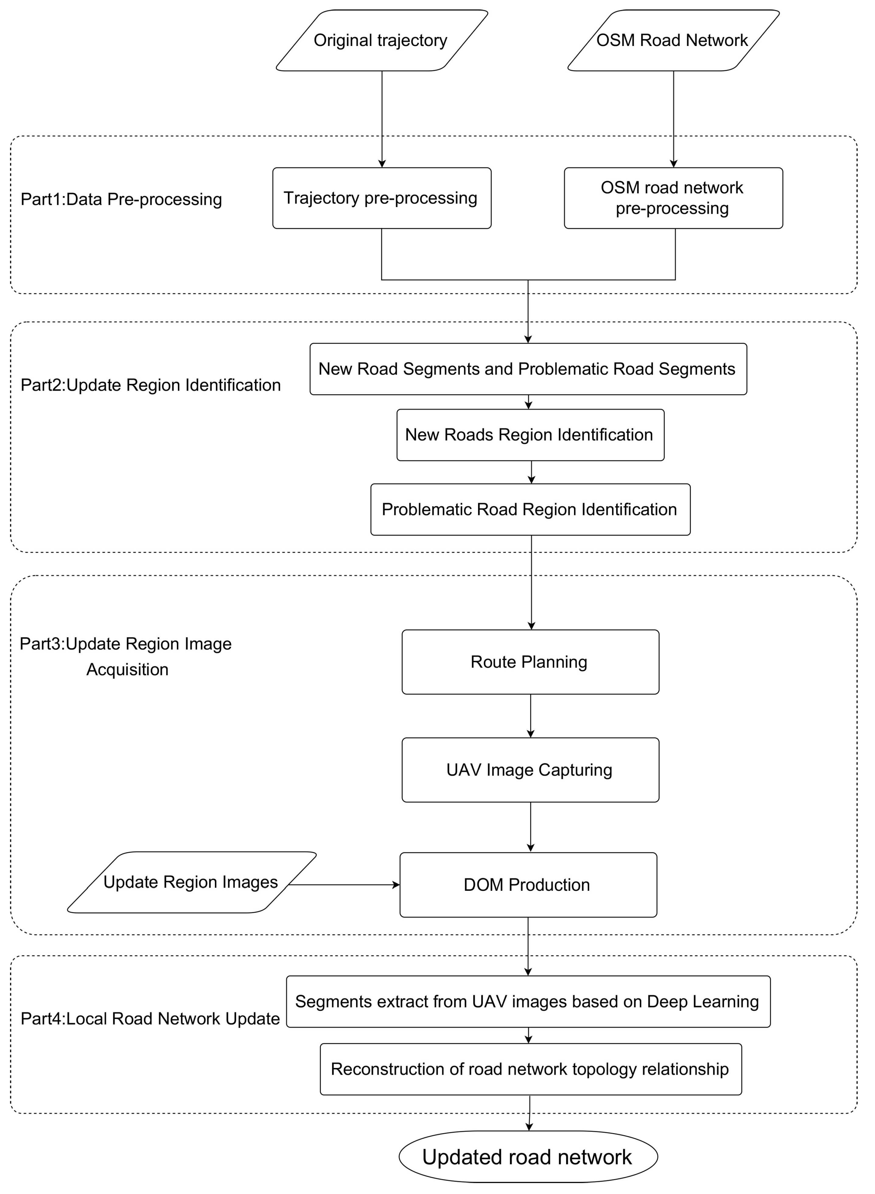
- Composite framework for road network update: The framework integrates the features of vehicle trajectory and image data to rapidly and accurately update the road network.
- Problematic road segment identification and extraction algorithm: The algorithm utilizes the relationship between trajectory points and corresponding road segments during HMM map-matching to identify and extract problematic road segments.
- Method to integrate UAV remote sensing imagery and deep learning techniques: The method is based on the characteristics of these two techniques to quickly acquire images of update regions and automatically extract road segment boundaries from the images.
2. Related Works
2.1. TB Methods
2.2. IB Methods
3. Methodology
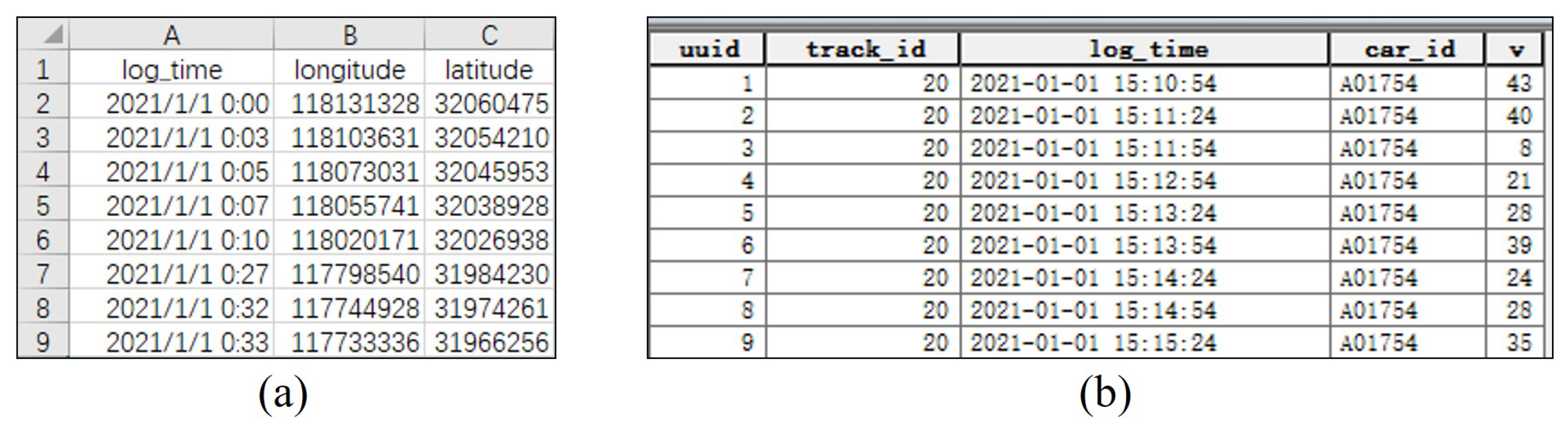
3.1. Data Pre-Processing
- Delete the trajectory points outside the study area.
- Obtain the distance (dist) between the different trajectory points based on longitude and latitude. Then, the velocity of the trajectory points can be obtained by the distance and the acquisition time .
- Obtain the license plate number from the file name of the original data.
- Eliminate the noisy points with speed less than 5 km/h or greater than 120 km/h.
- Number the trajectories and get the trajectory ID .
- Generate the trajectory point ID for each trajectory in increasing order starting from 1.
- Merge the trajectory file corresponding to each trajectory.
- Project the trajectory file to UTM. The final trajectory data shown in Figure 2b can be obtained.
3.2. Update Region Identification
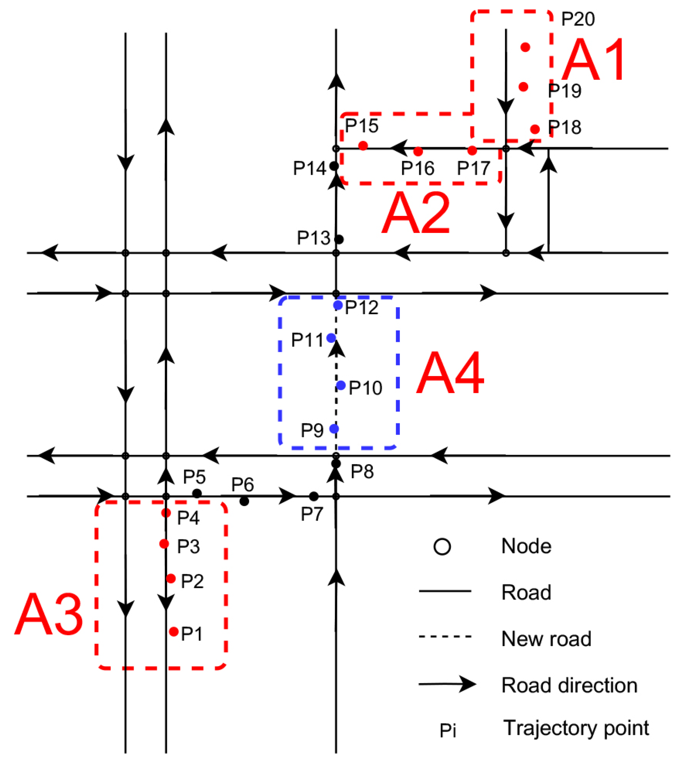
3.2.1. New Road Segments and Problematic Road Segments
- The original road segments were not updated on the road network system in time after reconstruction, including the situation shown in Figure 4a. As shown in Figure 3, there is a sequence of trajectory points in region A1. The original road segment is a one-way road segment, which was not updated in time after its expansion into a two-way road segment.
- The segment direction was updated incorrectly, which means that the road segment’s direction was updated to the road network system incorrectly, including the two cases shown in Figure 4b. One is the error of the one-way road segment that goes opposite to the actual situation, as shown in Figure 3 for the sequence of trajectory points in region A2. The other is the error of two-way road segments that have been updated into only one direction, as shown in the sequence of trajectory points in region A3 in Figure 3. These types of errors cannot be identified by visual interpretation.
3.2.2. New Roads Region Identification
- Input the road network G, the trajectory T, and the number of trajectory points N.
- Initialize dictionaries C, L, and S.
- Iterate over the trajectory points in the trajectory T. If there are projection points for , assign S to . Then, add S to C, and empty S again.
- Remove the trajectory points in the dictionary C from the original trajectory T. The remaining trajectory points L are the vehicle trajectories corresponding to the new road segments.
| Algorithm 1 Identify new road segments. |
| Input: Road network ; trajectories ; N.//N represents the number of points in T Output: The new road segment’s points .
|
3.2.3. Problematic Road Region Identification
- Obtain the projection points of the trajectory point and calculate the observation probability from the trajectory point to its projection points.
- Calculate the transmission probabilities between adjacent projection points.
- Find the set S of the sequence of trajectory points corresponding to the maximum probability path .
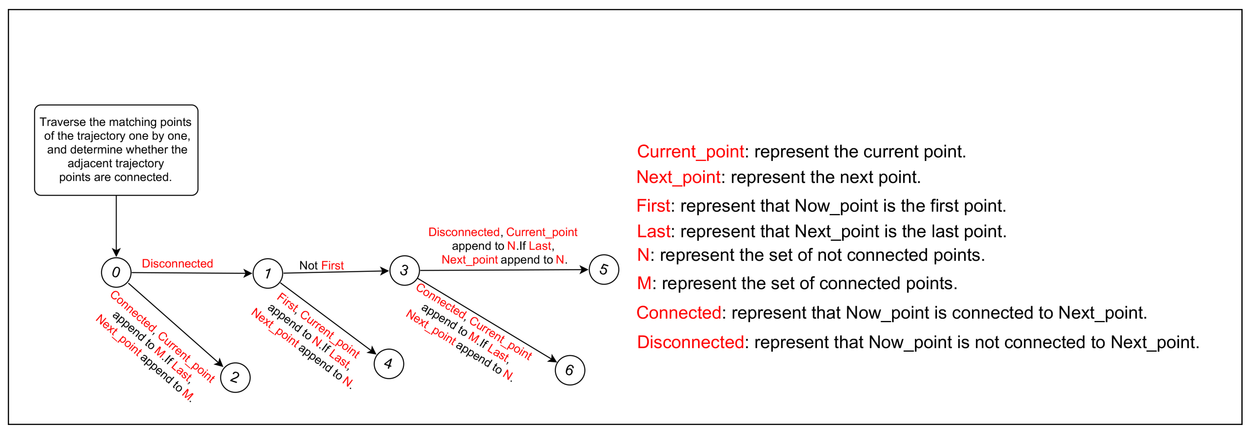
- Set the probability threshold and initialize N, M, and L as the empty dictionary. N represents the set of unconnected points, M represents the set of connected points, and L represents the set of problematic segments.
- If is connected to , add to M, as shown in steps 0-2 in Figure 5. If is also the last point of S, add it to M.
- If does not connected with , and is the first point of S, then is added to N, as shown in steps 0-1-4 in Figure 5. If is also the last point of S, add it to N.
- If all three conditions are satisfied: does not connect with , is not the first point of S, and is connected with its previous point; then, is added to M, as shown in steps 0-1-3-6 in Figure 5. If is also the last point of S, it is added to N.
- If all three conditions are satisfied: does not connect with , is not the first point of S, and is not connected with its previous point; then, is added to N, as shown in Figure 5, steps 0-1-3-5. If is also the last point of S, it is added to N.
| Algorithm 2 Identify and extract problematic road segments. |
| Input: Road network G = (E,V); Trajectory points C. Output: The problematic road segments
|
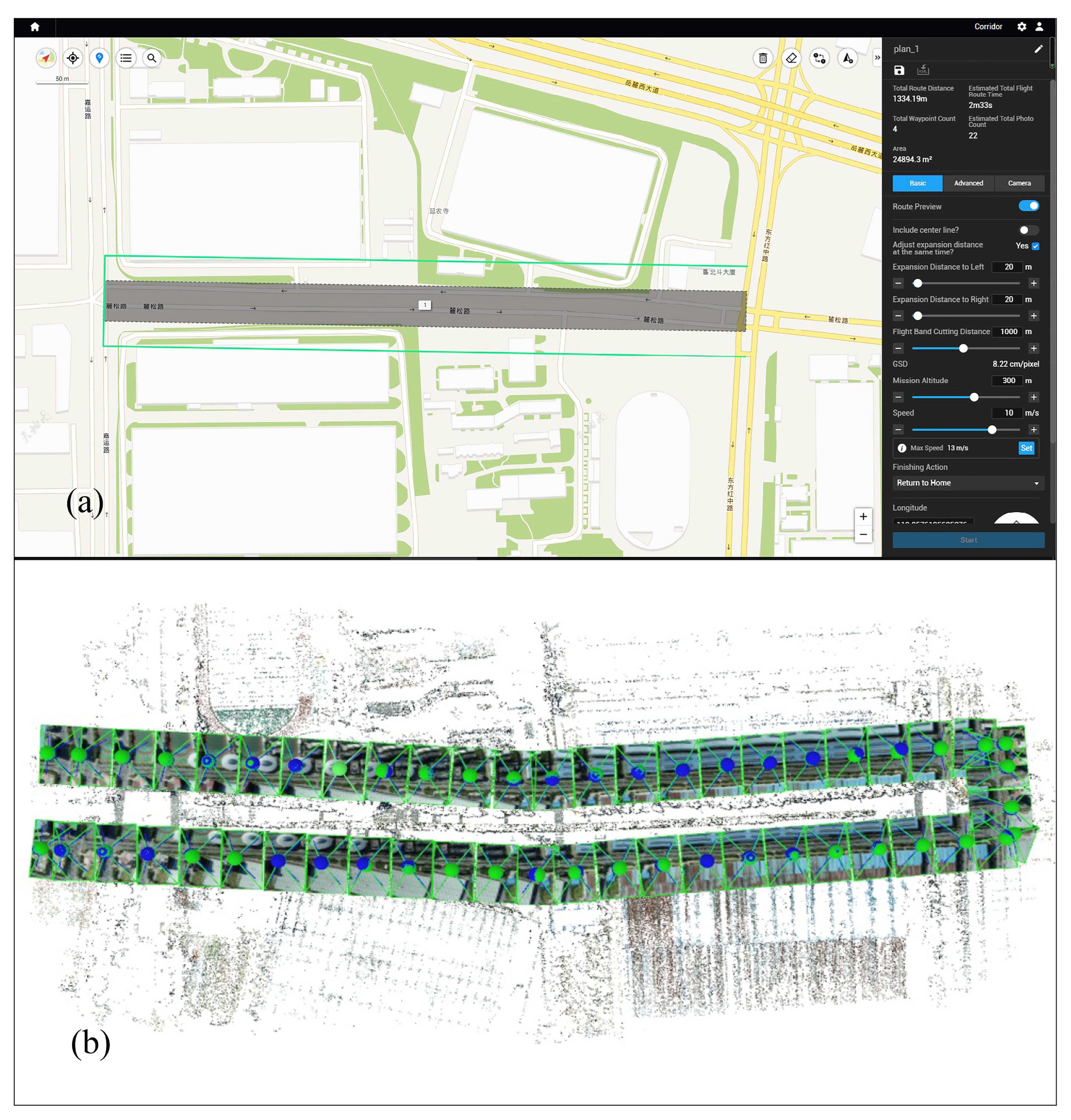
3.3. UAV Image Acquisition of Update Regions
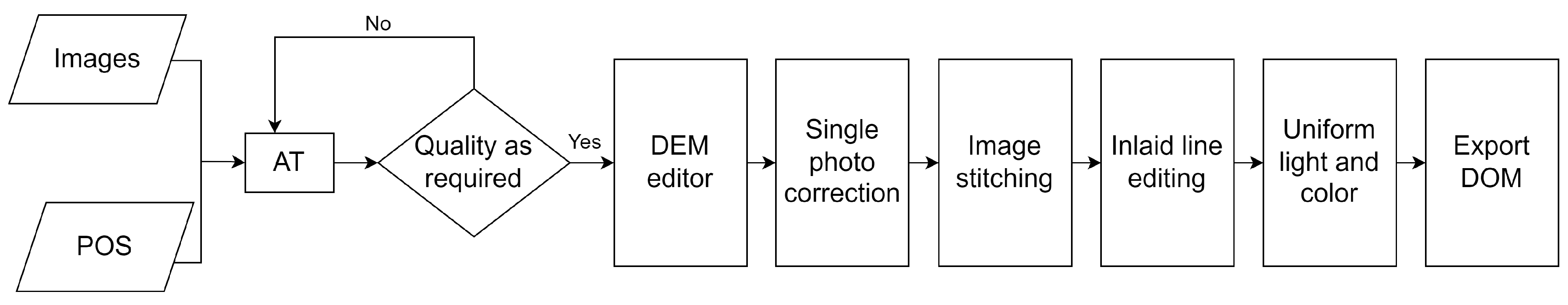
- Calculate the outer orientation elements of images by aerial triangulation.
- Use the DEM model to remove the distortions of images due to the irregular terrain.
- Splice the corrected images.
- Adjust the inlaid line.
- Unify the color and light of all images.
- Export the DOM of regions.
3.4. Local Road Network Update
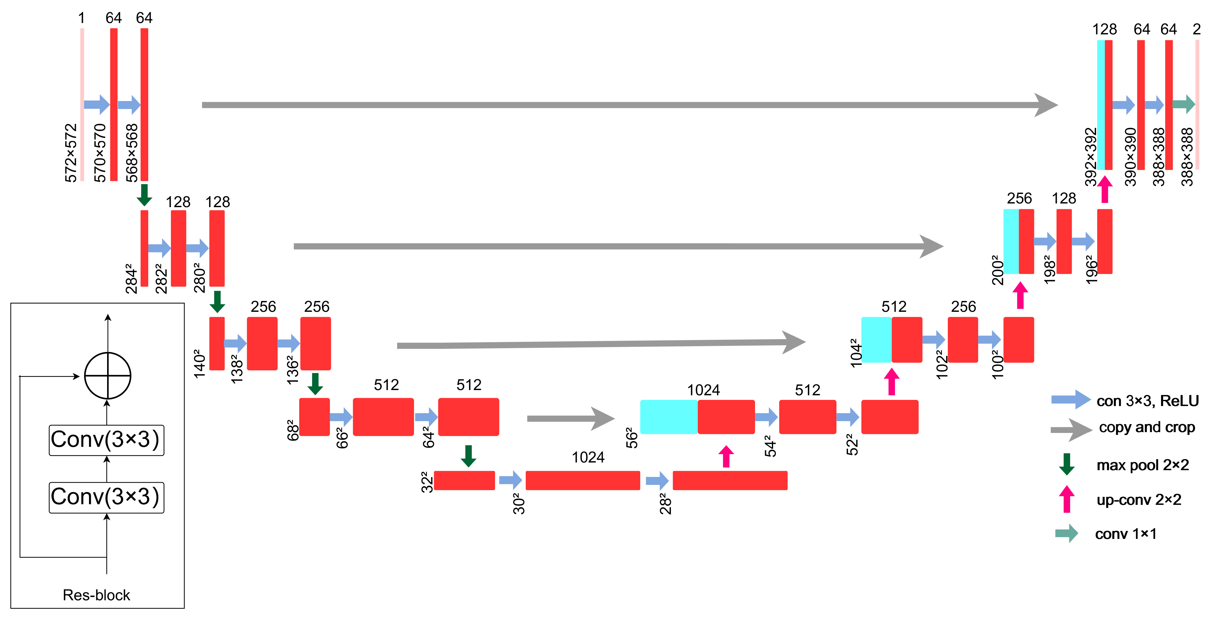
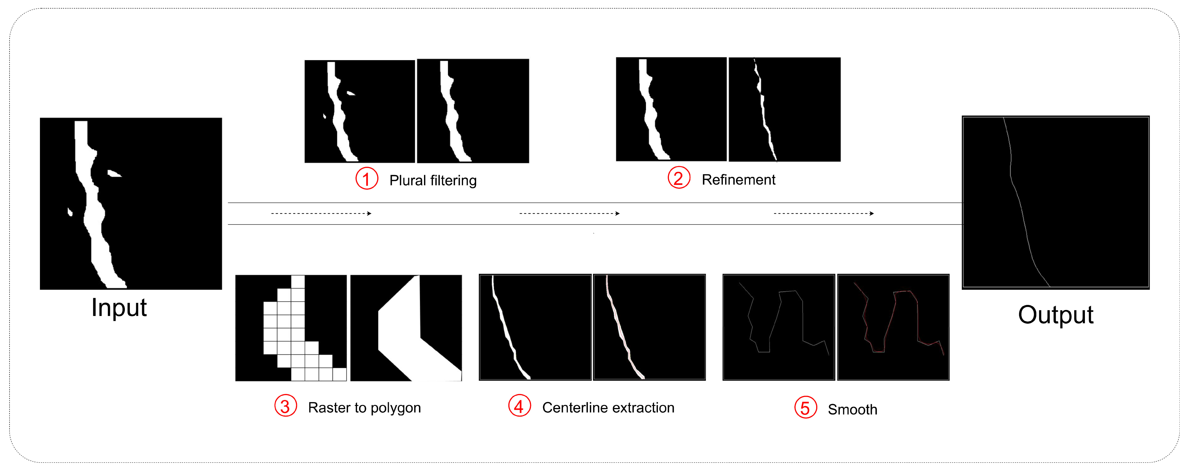
3.4.1. Deep Learning-Based UAV Image Road Segment Extraction
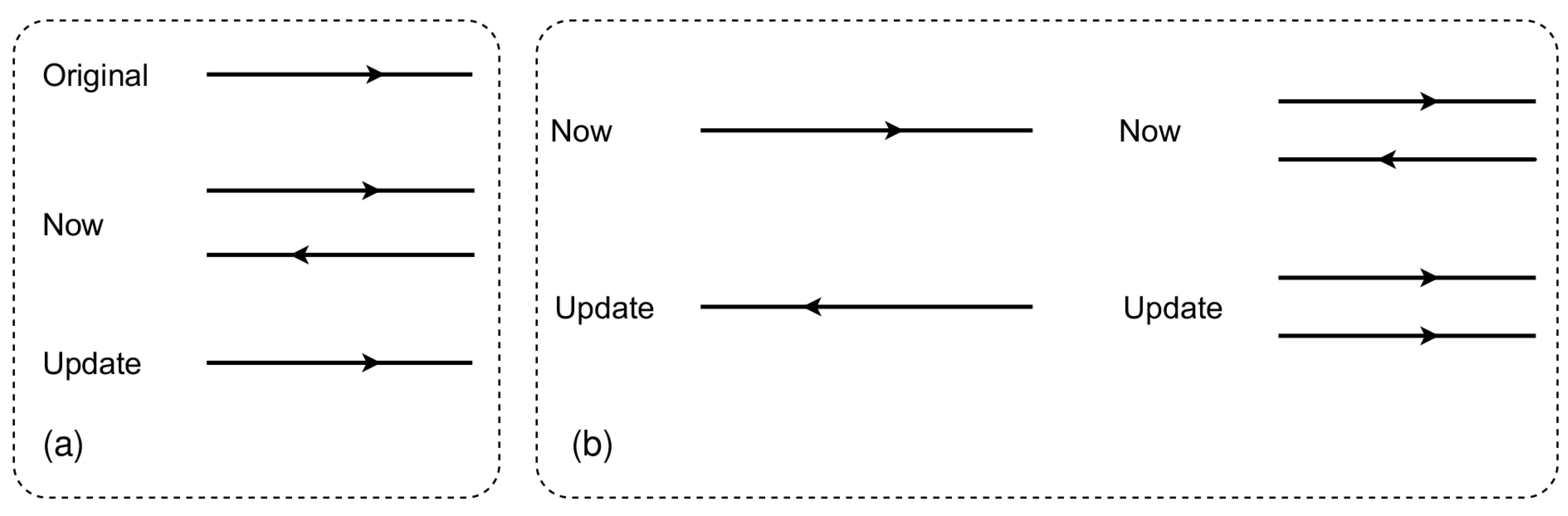
3.4.2. Road Network Update
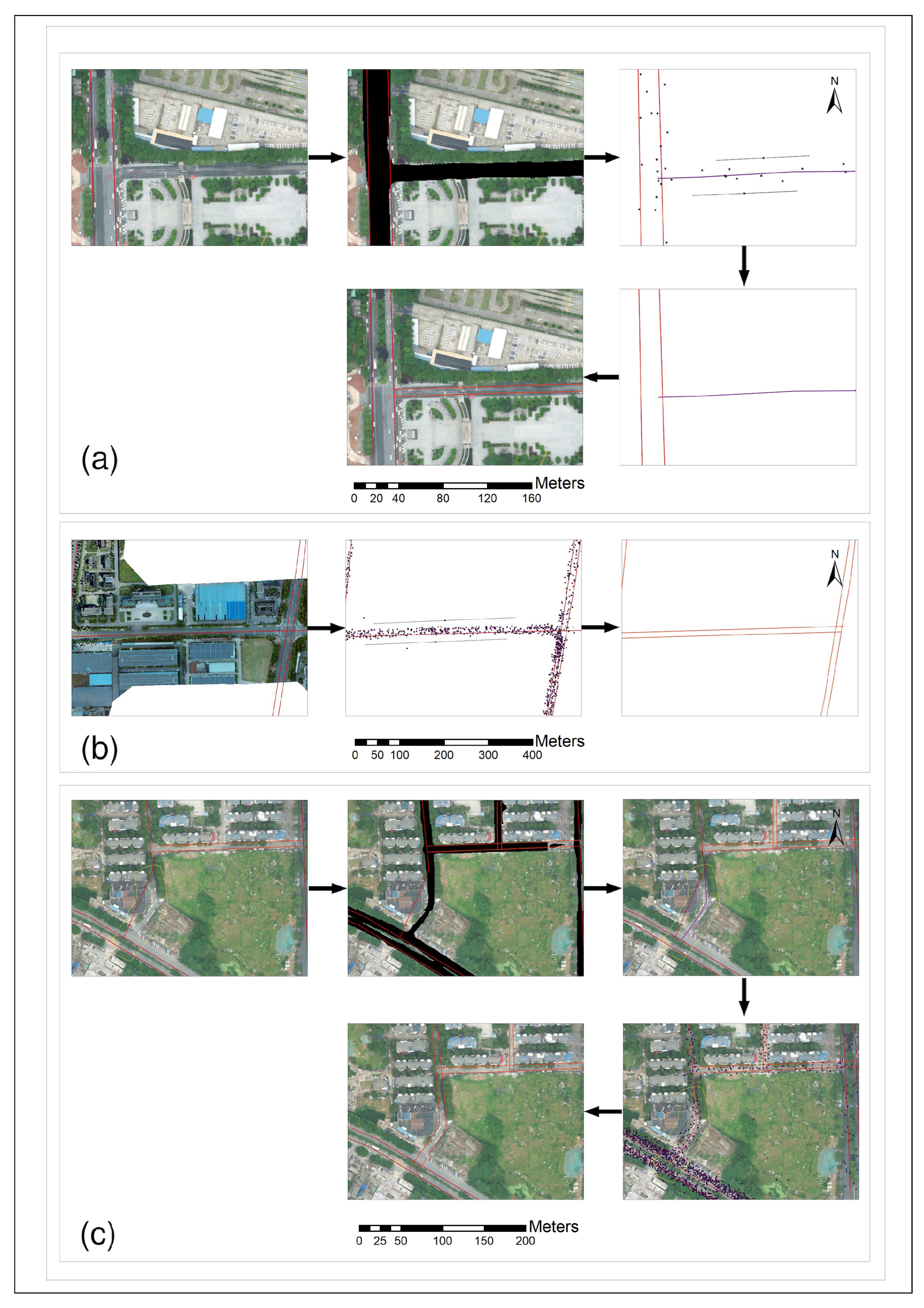
- As shown in Figure 9a, the directional attribute of the trajectory has been combined to update the road network, mainly to estimate the new road segment as a one-way or two-way road segment.
- As shown in Figure 9b, the road network has been updated using the directional property of the trajectory, specifically to identify whether the problematic road segment is a one-way or two-way road segment.
- As shown in Figure 9c, the direction attributes of the trajectory have been combined to update the problematic road segments with changed geometries and to estimate whether they are one-way or two-way segments.
4. Experiment
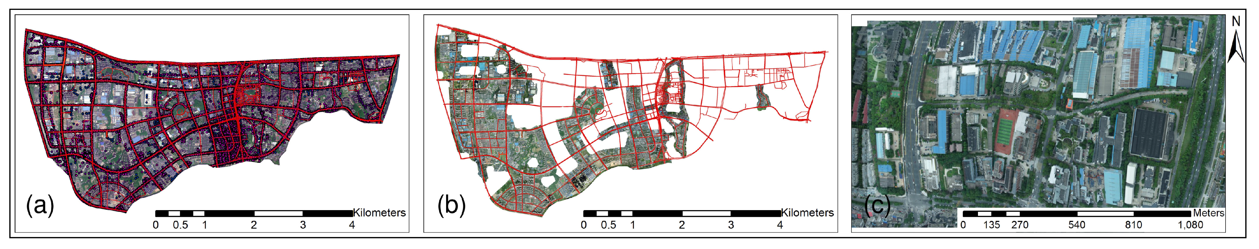
4.1. Data Introduction
- Extract the trajectory data within the research area according to the research range longitude to and latitude to .
- Calculate the speed and distance of the trajectory points according to the different positions and time differences between adjacent trajectory points.
- Slice sub-trajectories according to the time and distance thresholds between adjacent trajectory points.
- Renumber the sliced trajectories by obtaining the attribute of moving object ID from trajectory data.
- Number the trajectory points of each trajectory in ascending order starting from 1.
- Merge all trajectory data into one file and convert it to UTM-49N projection.
4.2. Evaluation Indicators
4.3. Experiment Result
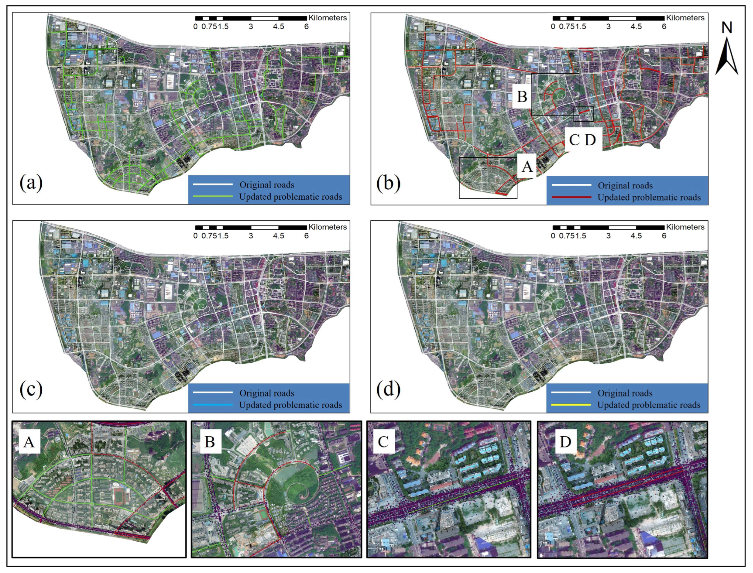
4.3.1. Comparison with the TB Method
4.3.2. Comparison with IB Method
5. Conclusions and Outlook
- A composite framework for road network update: The framework integrates the advantages of TB and IB methods to achieve rapid and accurate updating of road networks.
- Problematic road segment identification and extraction algorithm: The algorithm utilizes the topological relationships between adjacent matching points and the road network to identify and extract problematic road segments in the HMM map-matching process.
- Integrated UAV remote sensing imagery and deep learning techniques. The method can be applied to road network updating to automatically extract road boundaries and accelerate the speed of road network updating.
Author Contributions
Funding
Acknowledgments
Conflicts of Interest
Abbreviations
| TB | trajectory-based |
| IB | image-based |
| GPS | global positioning system |
| HMM | Hidden Markov Model |
| UAV | unmanned aerial vehicle |
| DOM | digital orthophoto map |
| CNN | convolutional neural network |
References
- Wu, T.; Xiang, L.; Gong, J. Updating road networks by local renewal from GPS trajectories. ISPRS Int. J. Geo-Inf. 2016, 5, 163. [Google Scholar] [CrossRef]
- Gong, J.; Xu, G. Spatial–Temporal Big Data Enables Social Governance. In New Thinking in GIScience; Springer: Singapore, 2022; pp. 253–264. [Google Scholar]
- Bhardwaj, A.; Sam, L.; Martín-Torres, F.J.; Kumar, R. UAVs as remote sensing platform in glaciology: Present applications and future prospects. Remote Sens. Environ. 2016, 175, 196–204. [Google Scholar] [CrossRef]
- Luo, Y.; An, D.; Wang, W.; Chen, L.; Huang, X. Local Road Area Extraction in CSAR Imagery Exploiting Improved Curvilinear Structure Detector. IEEE Trans. Geosci. Remote Sens. 2022, 60, 1–15. [Google Scholar] [CrossRef]
- Mor, B.; Garhwal, S.; Kumar, A. A systematic review of hidden Markov models and their applications. Arch. Comput. Methods Eng. 2021, 28, 1429–1448. [Google Scholar] [CrossRef]
- Zheng, Y. Trajectory data mining: An overview. ACM Trans. Intell. Syst. Technol. (TIST) 2015, 6, 1–41. [Google Scholar] [CrossRef]
- Kuntzsch, C.; Sester, M.; Brenner, C. Generative models for road network reconstruction. Int. J. Geogr. Inf. Sci. 2016, 30, 1012–1039. [Google Scholar] [CrossRef]
- Tang, L.; Ren, C.; Liu, Z.; Li, Q. A road map refinement method using delaunay triangulation for big trace data. ISPRS Int. J. Geo-Inf. 2017, 6, 45. [Google Scholar] [CrossRef]
- Chao, P.; Hua, W.; Mao, R.; Xu, J.; Zhou, X. A survey and quantitative study on map inference algorithms from gps trajectories. IEEE Trans. Knowl. Data Eng. 2020, 34, 15–28. [Google Scholar] [CrossRef]
- Renso, C.; Bogorny, V.; Tserpes, K.; Matwin, S.; de Macedo, J.A.F. Multiple-aspect analysis of semantic trajectories (MASTER). Int. J. Geogr. Inf. Sci. 2021, 35, 763–766. [Google Scholar] [CrossRef]
- Mariescu-Istodor, R.; Fränti, P. Cellnet: Inferring road networks from GPS trajectories. ACM Trans. Spat. Algorithms Syst. (TSAS) 2018, 4, 1–22. [Google Scholar] [CrossRef]
- Jo, K.; Sunwoo, M. Generation of a precise roadway map for autonomous cars. IEEE Trans. Intell. Transp. Syst. 2013, 15, 925–937. [Google Scholar] [CrossRef]
- Zhou, B.; Zheng, T.; Huang, J.; Zhang, Y.; Tu, W.; Li, Q.; Deng, M. A pedestrian network construction system based on crowdsourced walking trajectories. IEEE Internet Things J. 2020, 8, 7203–7213. [Google Scholar] [CrossRef]
- Huang, J.; Zhang, Y.; Deng, M.; He, Z. Mining crowdsourced trajectory and geo-tagged data for spatial-semantic road map construction. Trans. GIS 2022, 26, 735–754. [Google Scholar] [CrossRef]
- Tang, L.; Zhao, Z.; Yang, X.; Kan, Z.; Ren, C.; Gao, J.; Li, C.; Zhang, X.; Li, Q. Road crowd-sensing with high spatio-temporal resolution in big data era. Acta Geod. Cartogr. Sin. 2022, 51, 1070. [Google Scholar]
- Li, Y.; Xiang, L.; Zhang, C.; Wu, H. Fusing taxi trajectories and RS images to build road map via DCNN. IEEE Access 2019, 7, 161487–161498. [Google Scholar] [CrossRef]
- Davies, J.J.; Beresford, A.R.; Hopper, A. Scalable, distributed, real-time map generation. IEEE Pervasive Comput. 2006, 5, 47–54. [Google Scholar] [CrossRef]
- Elleuch, W.; Wali, A.; Alimi, A.M. An investigation of parallel road map inference from big GPS traces data. Procedia Comput. Sci. 2015, 53, 131–140. [Google Scholar] [CrossRef][Green Version]
- Wu, H.; Xu, Z.; Wu, G. A novel method of missing road generation in city blocks based on big mobile navigation trajectory data. ISPRS Int. J. Geo-Inf. 2019, 8, 142. [Google Scholar] [CrossRef]
- Guo, Y.; Li, B.; Lu, Z.; Zhou, J. A novel method for road network mining from floating car data. Geo-Spat. Inf. Sci. 2022, 25, 197–211. [Google Scholar] [CrossRef]
- Li, J.; Qin, Q.; Xie, C.; Zhao, Y. Integrated use of spatial and semantic relationships for extracting road networks from floating car data. Int. J. Appl. Earth Obs. Geoinf. 2012, 19, 238–247. [Google Scholar] [CrossRef]
- Tang, J.; Deng, M.; Huang, J.; Liu, H. A novel method for road intersection construction from vehicle trajectory data. IEEE Access 2019, 7, 95065–95074. [Google Scholar] [CrossRef]
- Cheng, D.; Yue, G.; Pei, T.; Wu, M. Clustering Indoor Positioning Data Using E-DBSCAN. ISPRS Int. J. Geo-Inf. 2021, 10, 669. [Google Scholar] [CrossRef]
- de Sousa, R.S.; Boukerche, A.; Loureiro, A.A. On the prediction of large-scale road-network constrained trajectories. Comput. Netw. 2022, 206, 108337. [Google Scholar] [CrossRef]
- Wang, Y.; Yu, B.; Zhu, F.; Zhang, J.; Huang, C. Hierarchical stroke mesh: A new progressive matching method for detecting multi-scale road network changes using OpenStreetMap. Soft Comput. 2021, 25, 3155–3173. [Google Scholar] [CrossRef]
- Ahmed, M.; Karagiorgou, S.; Pfoser, D.; Wenk, C. A comparison and evaluation of map construction algorithms using vehicle tracking data. GeoInformatica 2015, 19, 601–632. [Google Scholar] [CrossRef]
- Hashemi, M. A testbed for evaluating network construction algorithms from GPS traces. Comput. Environ. Urban Syst. 2017, 66, 96–109. [Google Scholar] [CrossRef]
- Zhang, J.; Wang, J.; Li, H. Topology Conflict Detection Considering Incremental Updating of Multi-Scale Road Networks. ISPRS Int. J. Geo-Inf. 2021, 10, 655. [Google Scholar] [CrossRef]
- Li, Y.; Peng, B.; He, L.; Fan, K.; Tong, L. Road segmentation of unmanned aerial vehicle remote sensing images using adversarial network with multiscale context aggregation. IEEE J. Sel. Top. Appl. Earth Obs. Remote Sens. 2019, 12, 2279–2287. [Google Scholar] [CrossRef]
- Abdollahi, A.; Pradhan, B. Integrated technique of segmentation and classification methods with connected components analysis for road extraction from orthophoto images. Expert Syst. Appl. 2021, 176, 114908. [Google Scholar] [CrossRef]
- Bastani, F.; He, S.; Abbar, S.; Alizadeh, M.; Balakrishnan, H.; Chawla, S.; Madden, S.; DeWitt, D. Roadtracer: Automatic extraction of road networks from aerial images. In Proceedings of the IEEE Conference on Computer Vision and Pattern Recognition, Salt Lake City, UT, USA, 18–23 June 2018; pp. 4720–4728. [Google Scholar]
- Bakhtiari, H.R.R.; Abdollahi, A.; Rezaeian, H. Semi automatic road extraction from digital images. Egypt. J. Remote Sens. Space Sci. 2017, 20, 117–123. [Google Scholar] [CrossRef]
- Abdollahi, A.; Pradhan, B.; Shukla, N. Extraction of road features from UAV images using a novel level set segmentation approach. Int. J. Urban Sci. 2019, 23, 391–405. [Google Scholar] [CrossRef]
- Abdollahi, A.; Pradhan, B.; Shukla, N.; Chakraborty, S.; Alamri, A. Multi-object segmentation in complex urban scenes from high-resolution remote sensing data. Remote Sens. 2021, 13, 3710. [Google Scholar] [CrossRef]
- Abdollahi, A.; Pradhan, B.; Shukla, N. Road extraction from high-resolution orthophoto images using convolutional neural network. J. Indian Soc. Remote Sens. 2021, 49, 569–583. [Google Scholar] [CrossRef]
- Abdollahi, A.; Pradhan, B.; Alamri, A. RoadVecNet: A new approach for simultaneous road network segmentation and vectorization from aerial and google earth imagery in a complex urban set-up. GISci. Remote Sens. 2021, 58, 1151–1174. [Google Scholar] [CrossRef]
- Abdollahi, A.; Pradhan, B.; Shukla, N.; Chakraborty, S.; Alamri, A. Deep learning approaches applied to remote sensing datasets for road extraction: A state-of-the-art review. Remote Sens. 2020, 12, 1444. [Google Scholar] [CrossRef]
- Alshaikhli, T.; Liu, W.; Maruyama, Y. Automated method of road extraction from aerial images using a deep convolutional neural network. Appl. Sci. 2019, 9, 4825. [Google Scholar] [CrossRef]
- Xiao, R.; Wang, Y.; Tao, C. Fine-grained road scene understanding from aerial images based on semisupervised semantic segmentation networks. IEEE Geosci. Remote Sens. Lett. 2021, 19, 1–5. [Google Scholar] [CrossRef]
- Gao, L.; Song, W.; Dai, J.; Chen, Y. Road extraction from high-resolution remote sensing imagery using refined deep residual convolutional neural network. Remote Sens. 2019, 11, 552. [Google Scholar] [CrossRef]
- Xin, J.; Zhang, X.; Zhang, Z.; Fang, W. Road extraction of high-resolution remote sensing images derived from DenseUNet. Remote Sens. 2019, 11, 2499. [Google Scholar] [CrossRef]
- Chen, Z.; Wang, C.; Li, J.; Xie, N.; Han, Y.; Du, J. Reconstruction bias U-Net for road extraction from optical remote sensing images. IEEE J. Sel. Top. Appl. Earth Obs. Remote Sens. 2021, 14, 2284–2294. [Google Scholar] [CrossRef]
- Cira, C.I.; Alcarria, R.; Manso-Callejo, M.Á.; Serradilla, F. A framework based on nesting of convolutional neural networks to classify secondary roads in high resolution aerial orthoimages. Remote Sens. 2020, 12, 765. [Google Scholar] [CrossRef]
- Chandra, N.; Vaidya, H.; Ghosh, J.K. Human cognition based framework for detecting roads from remote sensing images. Geocarto Int. 2020, 37, 2365–2384. [Google Scholar] [CrossRef]
- Dai, J.; Zhu, T.; Zhang, Y.; Ma, R.; Li, W. Lane-level road extraction from high-resolution optical satellite images. Remote Sens. 2019, 11, 2672. [Google Scholar] [CrossRef]
- Zhang, J.; Hu, Q.; Li, J.; Ai, M. Learning from GPS trajectories of floating car for CNN-based urban road extraction with high-resolution satellite imagery. IEEE Trans. Geosci. Remote Sens. 2020, 59, 1836–1847. [Google Scholar] [CrossRef]
- DJI Terra. Available online: https://www.dji.com/cn/dji-terra?site=brandsite&from=nav (accessed on 1 May 2022).
- Du, G.; Cao, X.; Liang, J.; Chen, X.; Zhan, Y. Medical image segmentation based on u-net: A review. J. Imaging Sci. Technol. 2020, 64, 1–12. [Google Scholar] [CrossRef]
- Wen, L.; Li, X.; Gao, L. A transfer convolutional neural network for fault diagnosis based on ResNet-50. Neural Comput. Appl. 2020, 32, 6111–6124. [Google Scholar] [CrossRef]
- He, H.; Yang, D.; Wang, S.; Wang, S.; Li, Y. Road extraction by using atrous spatial pyramid pooling integrated encoder-decoder network and structural similarity loss. Remote Sens. 2019, 11, 1015. [Google Scholar] [CrossRef]
- Biagioni, J.; Eriksson, J. Map inference in the face of noise and disparity. In Proceedings of the 20th International Conference on Advances in Geographic Information Systems, Redondo Beach, CA, USA, 6–9 November 2022; pp. 79–88. [Google Scholar]


| City | Time | Vehicles | Trajectories | Sampling Rate |
|---|---|---|---|---|
| ChangSha | 2021-01-01 to 2021-01-07 | 4817 | 33,179 | 30 s to 2 min |
| Method | Precision | Recall | F-Score |
|---|---|---|---|
| Our method | 85.31% | 80.80% | 82.99% |
| Deng et al. | 73.19% | 66.89% | 69.90% |
| Wu et al. | 76.07% | 58.94% | 66.42% |
Publisher’s Note: MDPI stays neutral with regard to jurisdictional claims in published maps and institutional affiliations. |
© 2022 by the authors. Licensee MDPI, Basel, Switzerland. This article is an open access article distributed under the terms and conditions of the Creative Commons Attribution (CC BY) license (https://creativecommons.org/licenses/by/4.0/).
Share and Cite
Qin, J.; Yang, W.; Wu, T.; He, B.; Xiang, L. Incremental Road Network Update Method with Trajectory Data and UAV Remote Sensing Imagery. ISPRS Int. J. Geo-Inf. 2022, 11, 502. https://doi.org/10.3390/ijgi11100502
Qin J, Yang W, Wu T, He B, Xiang L. Incremental Road Network Update Method with Trajectory Data and UAV Remote Sensing Imagery. ISPRS International Journal of Geo-Information. 2022; 11(10):502. https://doi.org/10.3390/ijgi11100502
Chicago/Turabian StyleQin, Jianxin, Wenjie Yang, Tao Wu, Bin He, and Longgang Xiang. 2022. "Incremental Road Network Update Method with Trajectory Data and UAV Remote Sensing Imagery" ISPRS International Journal of Geo-Information 11, no. 10: 502. https://doi.org/10.3390/ijgi11100502
APA StyleQin, J., Yang, W., Wu, T., He, B., & Xiang, L. (2022). Incremental Road Network Update Method with Trajectory Data and UAV Remote Sensing Imagery. ISPRS International Journal of Geo-Information, 11(10), 502. https://doi.org/10.3390/ijgi11100502