1. Introduction
The rapid increase in the human population in cities has brought about accelerated urbanization rates and challenges in traffic, energy use, pollution, and scarcity of resources [
1]. Coinciding with this process is the dawn of the fourth industrial revolution. In this age, societal advances are fueled by information through various vital technologies such as digital twins (DT), along with cloud computing, Internet of Things (IoT), big data, and artificial intelligence (AI) [
2]. These present opportunities to transform the management of cities to formulate informed decisions to solve or mitigate the challenges above. DTs are dynamic, virtual, digital representations of a physical system that mirror the physical reality through various data and can communicate with each other bi-directionally [
3]. However, various challenges still hinder their full realization. Full convergence of spaces is integral to the success of DTs in achieving their goals [
4]. However, the complexity of physical space makes it difficult. While multiple data models are already available, inconsistencies and indistinctness among models cause fragmentations in generating unified digital representations of the real world.
In these cities, urban environments have grown in complexity to accommodate the exponential growth of the human population and activities. This complexity has led to less familiarity with spatial layouts of structures, the burden of crowds, and more difficult recognition of landmarks [
5], leading to the demand for applications to aid mobility. However, with the fragmentation of data models representing the spaces and limitations of established location methods in continuously providing position [
6], developing and providing location-based services becomes difficult. Moreover, the outdoor aspect of spatial information is more well-developed than its indoor counterpart, partly because it is established separately [
7]. For instance, indoor space is viewed primarily in the context of the enclosed spaces of buildings where humans navigate as pedestrians. At the same time, in the outdoors, navigation occurs on street networks.
However, this fragmentation of spaces becomes apparent in the datasets when various formats represent them differently or independently developing applications. In the real world, human beings navigate continuously across indoor and outdoor spaces. Neither space exists in isolation [
8], even though they are modeled separately in applications. Furthermore, as spatial applications formerly outdoors find their counterparts also developed indoors, navigation research’s next challenge is integrating indoor and outdoor space. The data models and algorithms that serve as the foundation of LBS applications must accommodate the seamless movement of people from indoor to outdoor space and vice versa. Developing these models are essential in the planning and decision-making [
9], not just of policy-makers but also the residents and various stakeholders of these places.
As with any other cartographic representation, abstraction is inevitable when generating spatial datasets. For example, when using node-relation graphs (NRG) to denote connectivity relationships among 3D spaces, the dataset represents topological relationships and lacks geometrical properties [
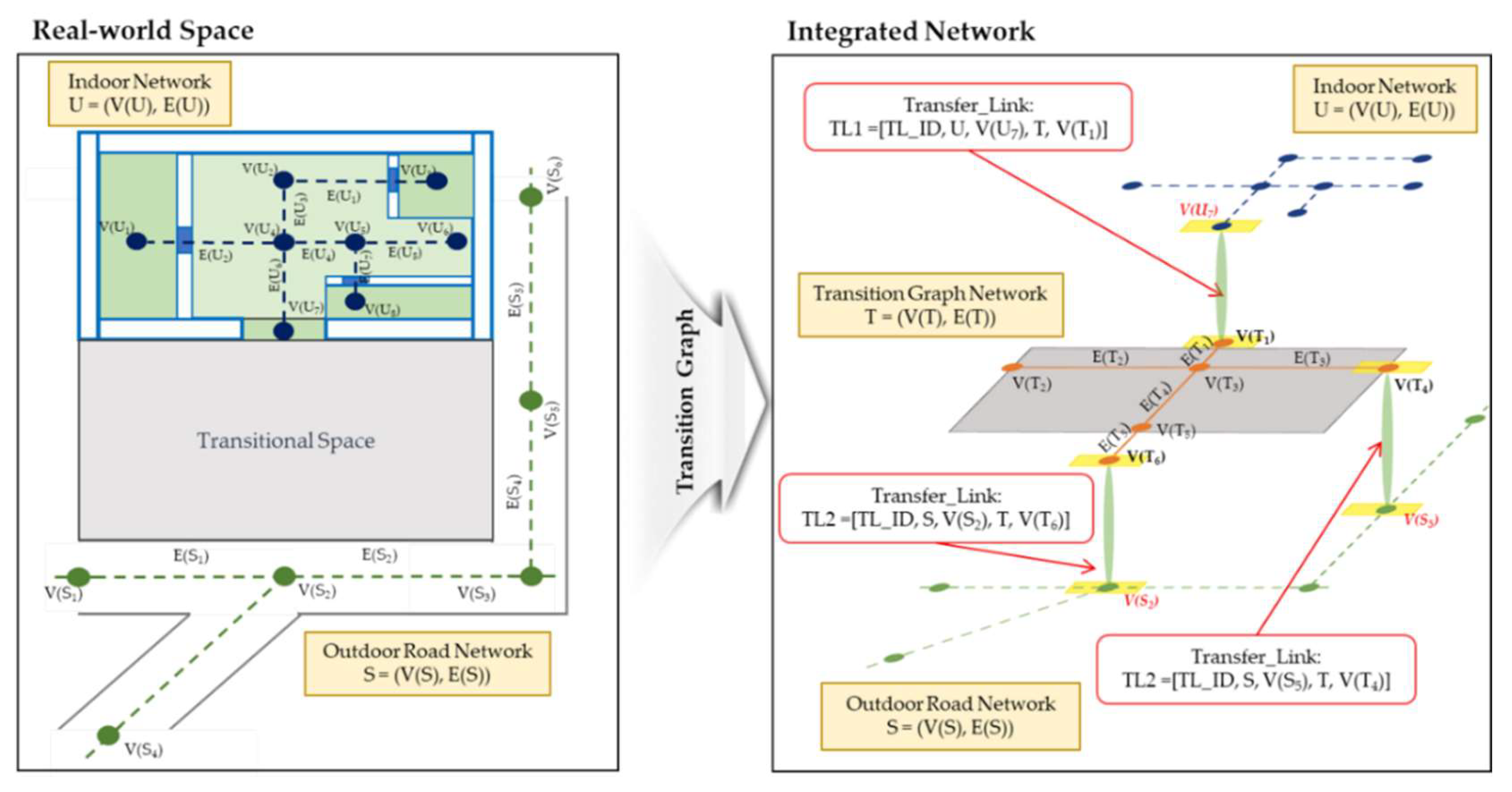
10]. Universal space is dichotomously classified either as belonging to indoor or outdoor space straightforwardly. However, as shown in
Figure 1, since spatial data represents the real world, certain parts of the continuous universal space are not represented. For example, road or street networks represent the outdoor network in navigation systems. The indoor network is expressed based on the compartmentalized rooms and the connecting hallways [
11]. Apart from these, navigational networks still omit a significant amount of space during the representation.
Simply put, to fully reflect navigation, the integration of indoor and outdoor network data must be established. While there is literature on continuous indoor–outdoor positioning techniques [
12] and even on semantic trajectory models [
13], a deficiency of integration in the space modeling aspect remains. At the same time, there are numerous similarities between these two spaces, unique properties of each that motivate separate data modeling to complicate their integration. Furthermore, physical (scale, dimension, structure) and experiential (agents, discontinuities, locating landmarks) disparities remain as challenges to build integrated systems [
14,
15]. Nevertheless, a versatile method for indoor–outdoor network integration will aid in the development of applications for guiding navigation activity and address data completeness.
Several works utilize the concept of an indoor–outdoor connection represented by a node or direct links [
16,
17,
18,
19,
20]. In these studies, the indoor and outdoor space data, although each aspect is represented differently in each study, were connected through the building’s entrances. As the Open Geospatial Consortium’s (OGC) Indoor Geography Markup Language (IndoorGML) [
21] has been published and has become the widely accepted and utilized standard for representing indoor space, especially in navigation applications, formally defining the integration with outdoor navigation data has also gained interest. The standard defines an anchor node as the connection between indoor and outdoor space through the entrance. However, the model is silent on its application and how to implement the connections.
Further studies extended this concept by defining IndoorGML elements to accommodate outdoor spaces [
22]. To avoid rewriting outdoor spatial data in IndoorGML, OGC also published an extension module capable of connecting to other data models [
23]. Still, methods presented in these approaches hold some inconsistencies in link definitions and complications, such as the need to convert node information to a new data schema.
Moreover, these studies are limited in representing a crucial part of the natural world between indoor and outdoor spaces. Studies have strongly suggested the existence of spaces that are neither indoors nor outdoors, but rather lie between the two [
11,
24,
25], but are still significant in size and navigable. As shown in existing studies, directly linking models for indoor and outdoor space is possible but restricts the portrayed movement of navigation agents.
The fragmentation of spatial representation becomes an issue in fully realizing digital representations of physical objects and real-world phenomena. Therefore, studies must examine integration across data models to provide applications that support seamless analysis. This paper proposes a framework for indoor and outdoor integration to support seamless navigation across these spaces. With this, we aim to provide a connection between network datasets that represent navigable spaces both in indoor and outdoor spaces. Furthermore, to overcome the limitations of existing approaches, we propose a method utilizing the spatial relationships of these spaces at their threshold locations. Thus, establishing connections between network datasets having different formats or database schemas becomes possible without data conversion or complicated implementations.
While having an integrated indoor–outdoor model representing navigable spaces is for the benefit of the navigation agents, this paper focuses on the data representing the spaces where these agents navigate. Hence, the characteristics of the agents are not considered but rather the relationships of the spaces that enable navigation. Essentially, whichever agent an application considers, the fragmentation within the spatial data into either indoors or outdoors impedes the reality of freedom of movement throughout these spaces. Furthermore, as we focus on the representation of spaces and their topological relationships, which contain and are independent of the agents, their positioning within the integrated space through a suitable localization method is not within the scope of the study.
We organized the paper as follows. The following section reviews related studies to navigation and integrating indoor and outdoor spaces. Then, we examine concepts concerning the connection between indoor and outdoor spaces and discuss the concept of transitional spaces. Following this section, we illustrate an experiment on sample data. The final section summarizes the study and further studies in this area.
2. Related Literature
As the world braces itself for the fourth industrial revolution, smart cities are being developed as applications of the widespread technological advancements of big data, IoT, and cloud computing. They also act as tools to detect and solve problems brought about by increasing urbanization [
3]. Digital twins are essential tools to realize real-time monitoring in the looming digital transformation of these smart cities. Using tools as mentioned above, data fuels effective decision-making by governments and resource managers [
2]. Moreover, DTs mirror the physical world in the virtual realm, integrated with interoperability and mutual communication. Thus, insights on complex urban phenomena can be obtained from high-quality and high-resolution spatiotemporal data while providing a comprehensive analytical and visualization strategy [
4,
26].
At the heart of these DTs are geospatial data, especially 3D building models [
1], that model the physical properties of space. For the DT to properly execute its functions and be a valuable tool for knowledge discovery, the spatial datasets must accurately reflect the complexity of the physical world. However, together with urbanization, physical space is becoming more dynamic and elaborate. DTs are complex systems composed of outputs from multidisciplinary fields. Hence it can be expected that various formats, standards, tools, and protocols must be integrated seamlessly and used simultaneously for a particular objective [
3]. In addition to the inconsistencies and fragmentation among spatial data models [
4], quality loss and challenges in simulation occur when integration is attempted [
27].
Furthermore, heterogeneous data sources and missing data remain the bottleneck of establishing mutual connections [
3,
26]. Given the multi-dimensional spatial data across various aspects of space, indoor/outdoor or surface/underground [
2], a unified model that describes space as comprehensively as possible is essential. Therefore, it is key to realize DTs with full model accuracy and harvest their potential to improve the quality of life for city residents.
Human beings naturally navigate indoor space to outdoor space and even towards another indoor space regardless of location. However mundane, this activity can become challenging when carried out in complex areas like urban neighborhoods. These locations are often congested, rapidly change, and may present restrictions based on time and where people navigate across levels and complicated layouts. [
24]. The area’s complexity, coupled with the insufficiency of information, emphasizes the need for location-based applications, especially for people lacking a sense of space and direction. Furthermore, in these areas, incidences of multimodal navigation are prevalent, especially in indoor spaces that may not be a building, such as subway stations. Several tools have been made available to aid navigation, such as placing maps in subway stations to illustrate the indoor structure and the neighboring outdoors [
28].
Initially, improving navigational services for pedestrians in providing seamless navigation has focused on developing applications based on pedestrian localization. However, since the Global Positioning System (GPS) only works outdoors, continuous positioning as the agent moves towards indoor space presents a problem. This situation demands suitable location methods that work seamlessly, achieved through a multi-sensor fusion model [
6]. Similarly, mobile crowdsensing data has guided users in subway stations with complex indoor layouts of their underground stations [
28].
Navigation in indoor and outdoor space can be differentiated mainly through size, dimension, or components. Applications portray indoor space mainly in 3D, primarily as a built environment. The smaller space and limited field of view demand local landmarks to guide navigation [
24]. In navigation models, indoor space is viewed in the context of human activity, containing boundary-constrained spaces and physically enclosed. On the other hand, outdoor navigation space relates to roads and streets. Despite these differences, navigation aspects remain the same. Navigation from one space to another is possible if the spaces are unobstructed and accessible [
11].
They also share multiple similarities, including concepts of connectors and passages, barriers, containers and nodes, and surfaces [
14]. Although these two have always been modeled and treated in applications separately [
15], indoor and outdoor space does not have a crisp boundary. Research has shown that spaces between and neither indoors nor outdoors exist through different elements that identify each space. These spaces challenge our perspective of how spaces are classified and direct us to reimagine how we strategize navigation and how we model it in applications.
Yan et al. (2019) established a framework for defining types of spaces for indoor–outdoor navigation. Based on how to work top-bounded spaces of built structures geometrically [
29,
30], this study defines the presence of semi-indoor (sI) and semi-outdoor (sO) spaces [
11]. Based on differences of indoor and outdoor spaces in characteristics and constraints, this framework classifies spaces based on lateral (side) closure and upper (top) closure, measured through defined thresholds, whether physical or virtual. Semi-indoor spaces are more enclosed above and less on the sides. These are often associated with spaces that are denied by GPS signals or in micro-climate situational studies. On the other hand, semi-outdoor spaces have more sides than top enclosures, correlated with mitigating effects and buffering conditions of the outdoors. Based on this framework, a suggested space hierarchy for some navigation agents is suggested, such as indoor and sI space for pedestrians, and sI and sO spaces for parking spaces. Geometrically, the boundaries of these spaces are also determined through space extraction algorithms in related studies [
29,
31]. This space classification became a basis for extracting the geometric boundaries of 3D navigable spaces extracted using 2D footprints and an elevation model. However, this study did not present an indoor–outdoor navigation-based data model following existing data standards.
Various standards have been made available to represent outdoor and indoor spaces over the years regarding the formal modeling of these spaces. Industry Foundation Classes (IFC) is a standard for building information modeling (BIM), highly focusing on semantic and geometric modeling of building features [
32]. Since this standard originated from the architectural, engineering, and construction (AEC) industry, information is inclined more to applications for the building interior and less on the outdoor environment. City Geography Markup Language (CityGML) [
33], on the other hand, presents various levels of detail for outdoor space. As an application schema for Geography Markup Language 3 (GML 3), CityGML is suitable for modeling cities and urban spaces.
With this in mind, a proposed Unified Building Model (UBM) demonstrates a model-oriented approach for simultaneously representing both indoor and outdoor space. UBM uses IFC and CityGML as information-content rich standards for real-world object modeling and design [
34]. Rather than as a conversion tool from IFC to CityGML, it presents an integrated environment for 3D City Modeling through identifying corresponding elements from each standard and simplifying through omission and merging towards a single model through geometric and semantic information. However, apart from basic spatial queries, the model lacks classes to enable navigation-oriented applications.
The development of the CityGML standard [
33] is the initial step in linking buildings and their immediate built environment. However, it still lacks information crucial to pedestrian access, especially in indoor space [
9]. Furthermore, indoor and outdoor spaces are still conventionally modeled separately in computer aided design (CAD) and geographic information systems (GIS), respectively. Most routing applications still lack the integrated model since most do not incorporate indoor routes and entrances/exits leading towards them. In some cases, there are entrances, but the indoor network is not present. There are cases too where both are unavailable [
35]. Quality of integration and how the model considers exit points play a factor in the resulting route guidance. Entrance data is critical in connecting indoor and outdoor spaces primarily when intended for multimodal routing applications [
35].
Despite these limitations, these standards have been utilized in efforts in space convergence for emergency and route planning applications. The node-relation structure (NRS) is the basis for most studies utilizing the network model to represent navigation spaces. NRS data representing connectivity of indoor spaces were connected to the street network through a particular node at entrance halls. Its main goal is to minimize entry point uncertainty to improve emergency response [
16]. To support navigation in an emergency response situation, Lee (2007) [
36] proposed a 3D navigable data model (3D NDM) derived from the geometric network model [
37]. In the 3D GNM, a network representation of the micro-scale built environment models the spaces’ connectivity relationships and geometric properties. The combined network comprises the internal layout of buildings and the street networks and models the connection of the two through a TransferEdge, containing information on which building entrance it connects.
Various studies have also undertaken similar approaches to connecting NRS to outdoor data. The Indoor Emergency Spatial Model (IESM), intended for a similar application, is heavily based on IFC classes to contain only building information critical for emergency response and management. A graph-based network, also based on the GNM, was generated using IFC geometry [
20]. Similarly, a Multi-Purposed Geometric Network Model (MGNM) was developed by Teo and Cho (2016), also using IFC classes for the indoor network. MGNM uses LoD1 CityGML models for the outdoor data and utilized an entrance-to-street strategy by converting BIM data to NRS [
18]. Similarly, Wang and Niu (2018) used OpenStreetMap primitives [
19]. Kim and Wilson (2014) indicated that connecting through the building entrances between 3D city models and the road network is vital to fully operational 3D routing applications [
17].
These studies prove that indoor networks play a crucial role in navigation and route planning [
16]. However, they also demonstrate less premium on representing a unified indoor–outdoor space model. The 3D NSM, the IESM, and the MGNM defined the connection through the entrance as a single point. Thus, the particular feature acting as the connection between the indoor and road network played the link between indoor and outdoor space. Furthermore, in the MGNM, most outdoor data only played a role in the visualization of the route plan.
IndoorGML is a standard published by OGC for representing, storing, and exchanging indoor spatial information and has been utilized widely in studies for navigation applications [
38,
39,
40,
41]. For example, Jung and Lee (2017) [
38] extended IndoorGML to accommodate the representation of spaces using omnidirectional images for indoor patrol service. Ahn et al. (2020) [
39] used a spatial data fusion approach to integrate said images directly to IndoorGML data. Furthermore, approaches to generate IndoorGML data from IFC and OpenStreetMaps have been presented by Khan et al. (2014) [
40] and Mirvahabi and Abbaspour (2015) [
41], respectively. However, it is common in these studies that while IndoorGML can characterize space well to support navigation applications, these have focused on its function solely in the indoor environment.
Nevertheless, the main IndoorGML standard document acknowledges the importance of connecting indoors and outdoors in navigation applications. The standard coins the Anchor Node, which denotes an indoor space’s entrance (or exit) as a particular node in the topological graph [
21]. This standard describes that the Anchor Node requires defining additional elements, such as information on the connection between indoor–outdoor space and transformation parameters for coordinate reference systems (CRS). However, it does not define the Anchor Node in the core and navigation models. There are also no definitions of connections to either the rest of the indoor or outdoor networks. Moreover, there are no specific examples and specifications on implementations.
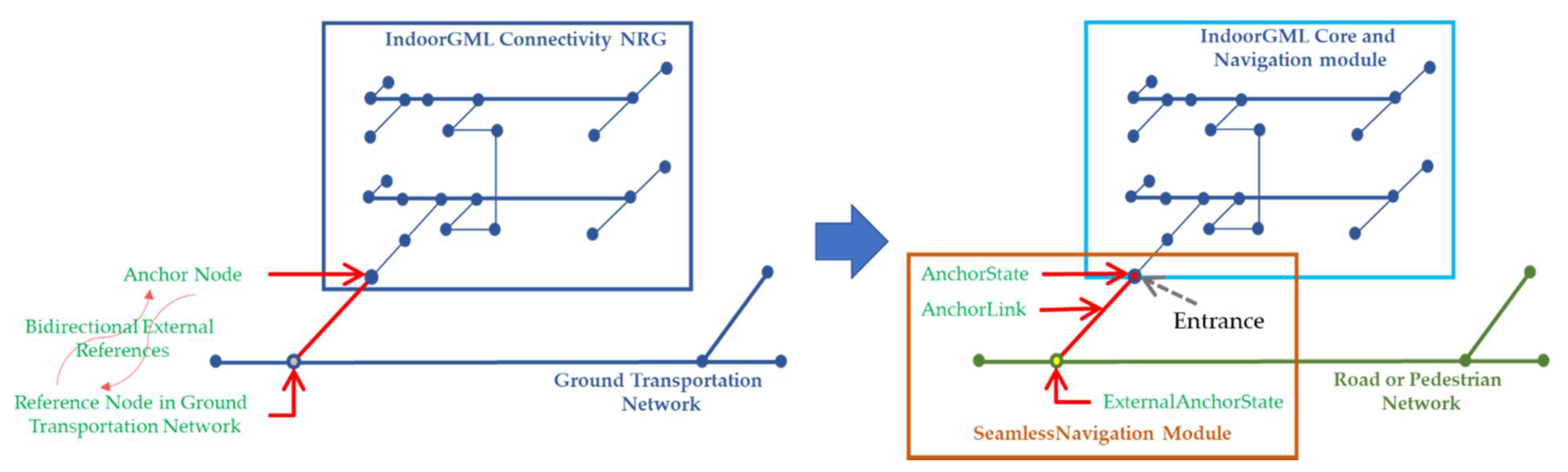
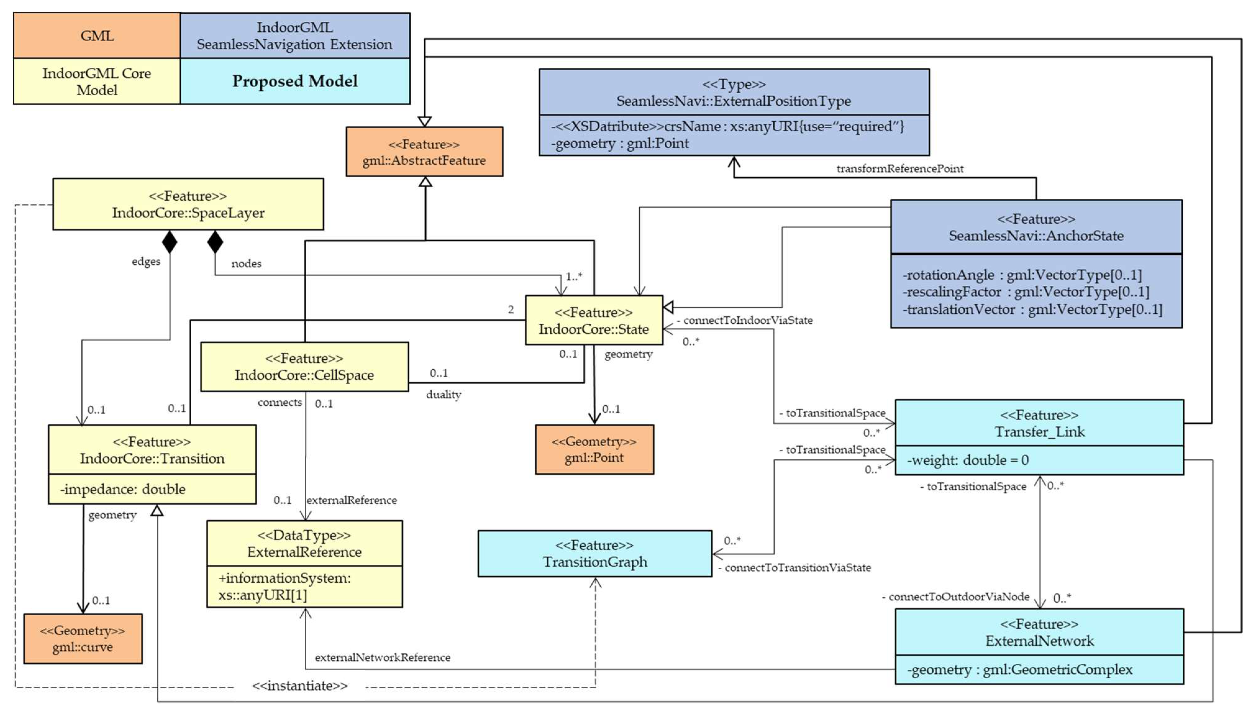
A discussion paper supplemented the originally-published IndoorGML standard [
42], improving upon the original definition of the AnchorNode, shown in
Figure 2. The supplement accommodates the demand for continuous navigation from indoor space towards outdoor space. The SeamlessNavigation Module is available in three elements: AnchorState, AnchorLink, and ExternalAnchorState. The unified modeling language (UML) class diagram shows the IndoorGML SeamlessNavigation module data model based on the IndoorGML core and navigation modules. AnchorState is the node that connects the indoor space and outdoor space, or in other words, a control point for indoor–outdoor integration. ExternalAnchorState represents a node that represents the position on the outdoor network. It is represented geometrically as Point in GML since it represents one of the endpoints of curve geometry of AnchorLink. Finally, the AnchorLink connects the AnchorState and ExternalAnchorState.
However, this specification still has some limitations. First, the anchor node discussion paper’s definitions of the nodes in the SeamlessNavigation module necessitates conversion. In the UML, for instance, the AnchorState inherits from the state class. Hence, a conversion from the state entity representing the entrance to an AnchorState is necessary. Conversion is also necessary for the node in the outdoor transportation network to an ExternalAnchorState. The additional step of conversion adds to the computational load in applications. It makes integration less efficient because the input datasets are modified. On top of these, some edges would have to connect nodes having different characteristics, which would pose difficulties in implementation. For example, the AnchorLink may connect an IndoorGML node and a node derived from CityGML data. Other edges in a similar situation include those connecting the ExternalAnchorState and the other road network nodes and those that connect the AnchorState to the indoor network.
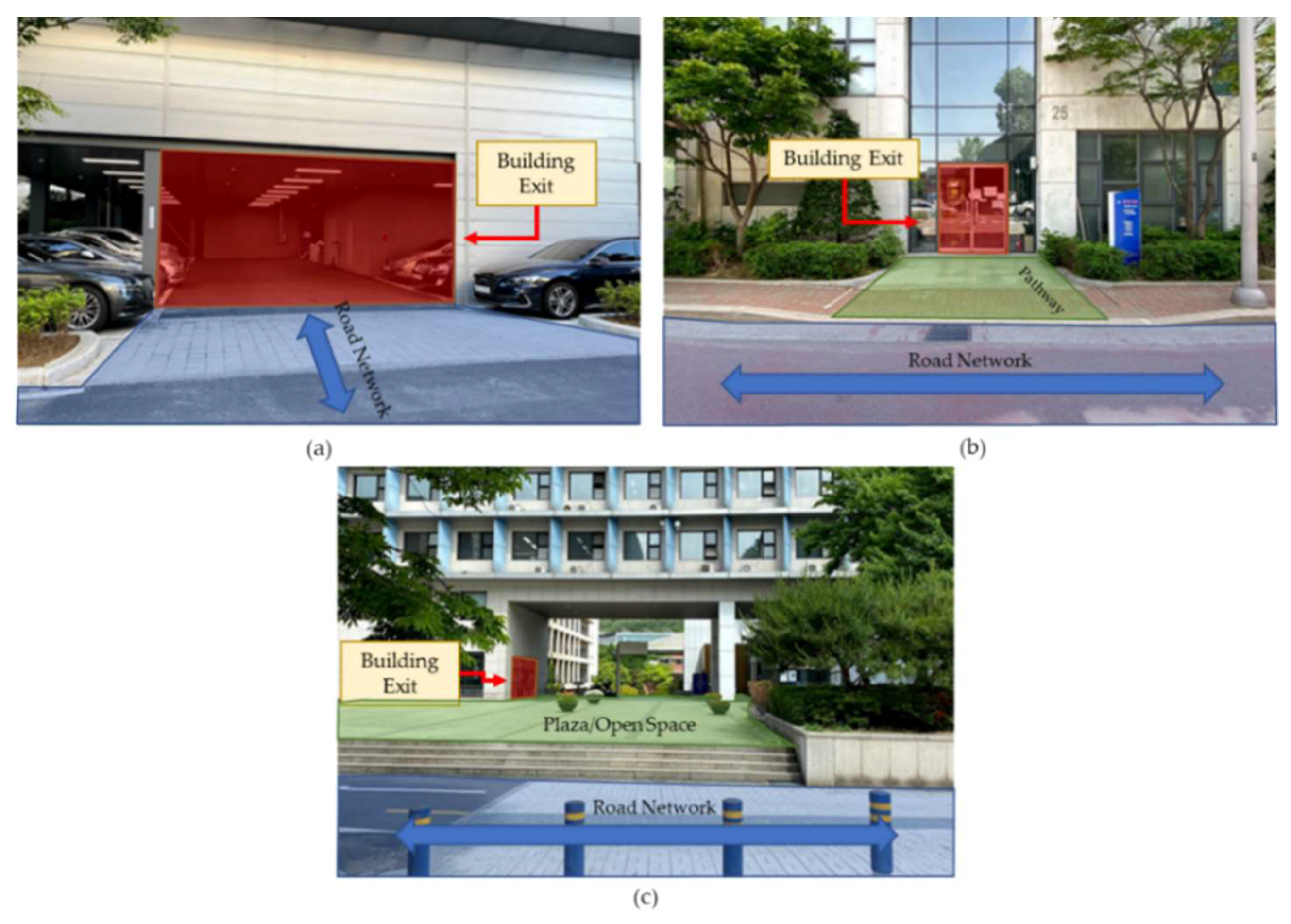
The model’s approach of directly connecting the entrance to the road through a single AnchorLink edge is a rather simplistic method. The SeamlessNavigation module assumes that the indoor network and the outdoor network are in the immediate vicinity. In reality, spaces between building entrances and the transportation networks vary in form, size, and extent. Therefore, indoor and outdoor space integration must consider general cases of intermediate spaces between buildings or between the building and the road network, including large open spaces. Furthermore, while this approach is relatively simple and directly implementable, the building is treated as isolated instead of being a component of a seamless environment along with its surroundings.
4. Experimental Implementation
In this section, we select a study area with experimental datasets to demonstrate the implementation and potential use of the proposed model.
Figure 10 shows the experimental data based on an academic building within a university campus and its surrounding environment. We generate the indoor geometric network of each building and road in the intermediate vicinity of the two structures from geometric data derived from a 1:5000 topographic map and floor plans. The potential benefit of the described model in developing a seamless navigation-oriented application is demonstrated by implementing an optimal path search from the indoor network of an above-ground building, passing through street-level transportation data towards a navigation target of an outdoor bus stop, based on IndoorGML-based network data.
This experiment aims to demonstrate that the connection between the indoor and outdoor network datasets through a transitional space is possible using the proposed model. This implementation will focus on route analysis, a primary navigation-based activity. Based on
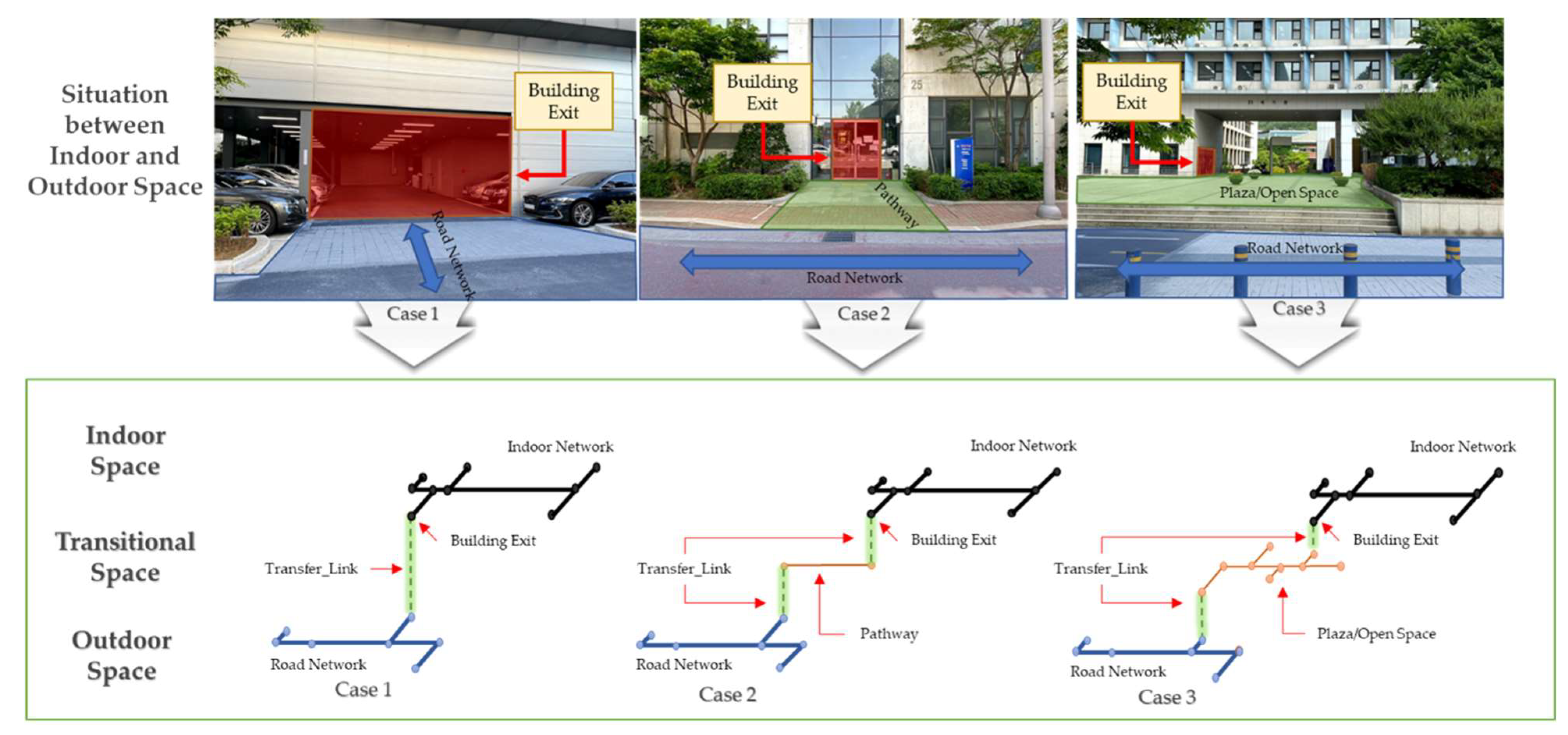
Figure 4, the experimental area belongs to Case 3, having a plaza-type area in front of the building.
Figure 11 shows the IndoorGML-based network data for the building. This case study will explore connecting the indoor network to the outdoor transportation network through the plaza.
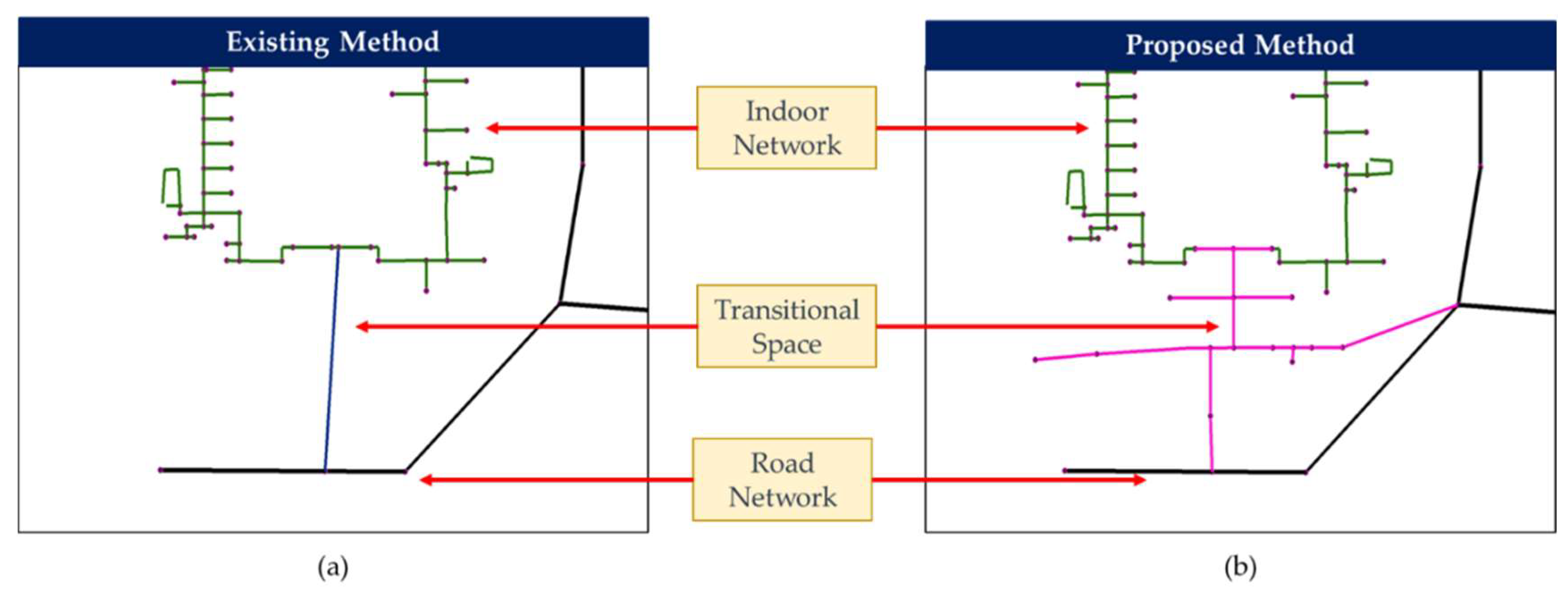
We generated network datasets based on the SeamlessNavigation extension module and based on the model presented in the previous section to compare the representation of space connection among the two methods. The result for the two approaches of representing the plaza through network data is in
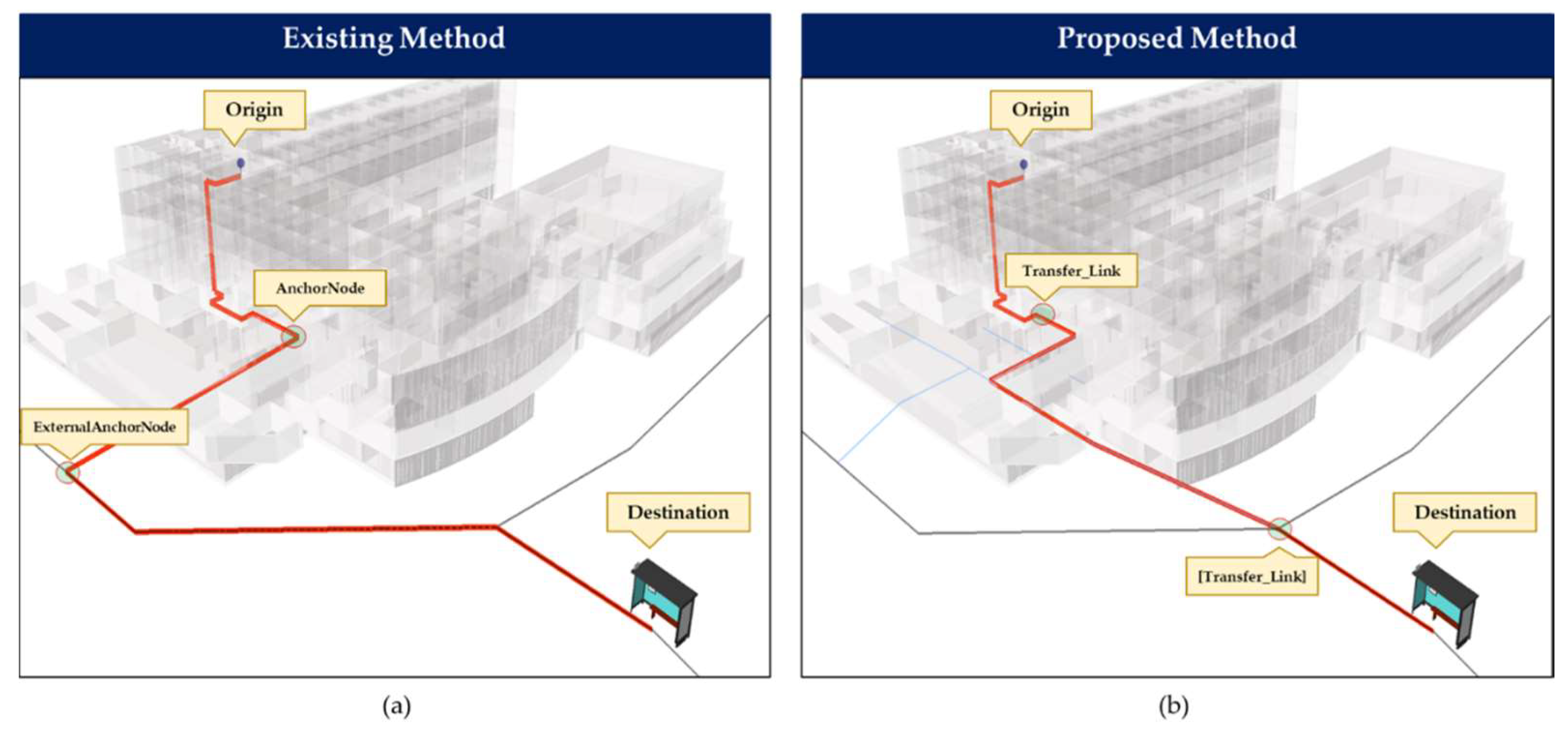
Figure 12. First, in
Figure 12a, through the anchor node concept, the exit point of the building must be converted to a single AnchorState, as specified in the extension module. However, since the building has two exits, both locations are combined and converted into a single anchor state to represent a single connection between the indoor and outdoor space. We convert the closest node in the road network to an ExternalAnchorState. The two converted nodes are consequently connected directly through an AnchorLink. We generate the transition graph composed of several states and transitions for the proposed model, as shown in
Figure 12b. We retained nodes in the indoor network representing the exits and connect them to states in the transition graph that correspond to the same exits. Connections are through Transfer_Links with lengths of zero. We also establish similar Transfer_Link relationships in the locations where the transition graph meets the outdoor road network in two points at the building frontage and the three-way intersection.
The dataset used to represent the proposed method is detailed further in
Figure 13. We used a point on the 7th floor of the building and an outdoor bus stop as origin and destination points of the route analysis. We combine the indoor network for the building, road network, and either the Anchor Node or Transition Graph data in a single Feature Dataset to generate a route analysis layer. We assigned the identified origin and destination points as stops. Finally, we designated the length of the edges signifying connectivity relationships as impedance attributes.
As shown in the previous section, the integration relies on topological relationships to avert the need for data conversion or modification of input data. Hence, the integrated data must exhibit a connection between the indoor network of the building and the outdoor transportation network to successfully implement navigation between the indoor environment and the outdoor facility. To demonstrate this, we performed the optimal path search across the connected networks by calculating the minimum cost path in 3D space using a procedure based on a modified Dijkstra’s algorithm [
46]. Algorithm 1 details the algorithm, and we implemented it using the Network Analyst tool of ArcGIS through the Model Builder tool.
| Algorithm 1. Optimal path determination based on modified Dijkstra’s algorithm [46]. |
| Algorithm Indoor–outdoor integrated network optimal path routing algorithm |
1 InOutRouting [: network , : list
2 of indoor networks , list of transition graph
3 networks , : list of Transfer_Link connections,
4 : node, ]
5 find Network or containing and
6 if contains or , add and neighbor to
7 if contains or , add to
8 add to
9 find Network in containing
10 for each TransferLink in Network
11 add to list
12 for each in : find node in connected to
13 calculate = OptimalPath [, , ]
14 add to
15 remove from
16 while is not :
17 find Network in containing elements of
18 for each Transfer_Link in Network : add to
19 for each in : find nodes in connected to
20 remove from
21 if is
22 find nodes in connected to
23 calculate = OptimalPath [, , ]
24 add to
25 for each in :
26 for each in :
27 InitOptimalPath = min ( +
28 else: for every in
29 calculate = OptimalPath [, , ]
30 add to
31 for each in :
32 FinalOptimalPath = min (InitOptimalPath + )
33 remove from
34 return
35 function OptimalPath []:
36 create node priority queue ,
37 for each node in :
38 if : , ;
39
40 while is not empty:
41 for each neighbor of :
42
43 if , ;
44
45 if : = empty sequence
46 if is defined or :
47 while is defined: {insert at start of , }
48 return OptimalPath |
The main inputs of the algorithm are the origin and destination points. Together with this, the outdoor network , the indoor networks in a list (should there be multiple buildings along the span of the outdoor network), transition graphs in a list , and the list of Transfer_Link connects the networks. The input networks must also specify the attribute containing the impedance value that the algorithm uses in the route calculation.
In lines 34–47, the sub-function in the algorithm calculates the optimal path between a source (origin) and a target (destination) point within a network using a priority queue. Initially, in line 40, the algorithm calculates for node with a minimum impedance value ( variable). We use the expression length [u,v] to solve the impedance at the edge joining and neighbor . The variable is the total length from the source to a neighbor if it passes through . It replaces the current if it is of smaller value. Through an iterative loop from the target source, the optimal path is traced based on all adjacent edges having the minimum impedance.
The primary function in lines 1–33 implements the sub-function for networks connected by Transfer_Links, through an iterative process through each of the connected networks. Routing problems may either be from indoor space to outdoor space, outdoor space to indoor space, or from an indoor space to another indoor space. In either case, transition graphs may (as in Case 2 and Case 3 in
Figure 5) or may not (as in Case 1) be present. Lines 4–7 is a method to narrow down all given data to identify which possible networks may contain the optimal route necessary for calculation efficiency. The algorithm generates a subset of the given data called
from the networks that contain either the origin node
or the origin node
through a conditional process in lines 18–20.
Since route paths may begin or end either indoors, outdoors, or at the transitional spaces, the algorithm identifies the the network containing . As shown in lines 8–14, within this network, all nodes connected to Transfer_Links will be identified because multiple Transfer_Links may connect this network to a neighboring network. For each of these nodes, optimal routes from must be calculated respectively as . is then removed from the .
The neighboring network connected through must be identified, and the connecting nodes will be used as new temporary origin points. Within this neighboring network, the nodes that have Transfer_Links that connect to other neighboring networks will be identified and set as temporary destination points. Similarly, optimal routes from to within are stored as . is then removed from the . The sub-function identifies the initial least-cost path from the possible paths from starting point to these temporary destination points, as shown in Line 24–26.
The algorithm repeats this process, from lines 16–33, until there is no more network in the . If in , the only present is the one connecting to the previous network, it means that contains . In this case, the sub-function calculates the optimal route from the earlier temporary destination points to and stored at . Finally, the algorithm, at lines 30–31, assigns the route that has the minimal total impedance across , and as the final optimal path from the origin point to the destination.
The result of the shortest path analysis was overlaid to the geometric data and shown in
Figure 14.
Figure 14a shows the result of the integrated network based on the SeamlessNavigation module. From the origin point, the route went down the elevator shaft towards the building exit point. Results demonstrate the connection of indoor space to outdoor space as the route starting from AnchorState at the exit, straight through the AnchorLink, and towards ExternalAnchorState on the road network directly in front of the building. From this point, it approached the three-way intersection and directly made its way to the bus stop on the outdoor network. Indeed, as previous works [
23,
42] have demonstrated, the SeamlessNavigation module can provide a connection between indoor and outdoor space through spatial relationships. However, this process has to modify the input data in the building exit nodes, and a single edge abstracts the transitional space without regard to its extent in the real world.
In contrast, the second result in
Figure 14b shows the route on the Transition Graph-based network based on the proposed model. The route started similarly to the previous case until the building exit, continuing to the transitional space through the Transfer_Link. Following a shorter, different route through the plaza, it proceeded directly to the three-way intersection towards the outdoor road network through another Transfer_Link until the destination point.
Figure 15 shows more details about the route in
Figure 14b. The algorithm calculates the shortest route within the first network, i.e., the indoor network, between the origin point to either of the states for the two building exits, each having Transfer_Links connecting to the transition graph. Using the presented algorithm, the optimal route from
to
and from
to
is calculated. Then at the connected network, the Transition Graph, the nodes at
and
are identified as temporary origin points. At the same network, other nodes at other Transfer_Links
and
are set as temporary destination points. Similarly, the procedure calculates optimal paths using these points. Finally, the best route from this
and
to the bus stop on the outdoor roadside is calculated.
The route having the minimal overall impedance among the intermediate routes start from
, passing through the north exit at
. At the inset
Figure 15a, the connection at the
enables the connection from the indoor network and the transfer graph at the two nodes representing the same entrance in those respective networks. The route turns left at the transitional space towards the three-way intersection at
until it reaches the bus stop designated
. In
Figure 15b, the connection at the
enables the connection from the transfer graph to the outdoor network at the connected nodes. Compared to the previous case, this representation provided a more realistic route. This route reflects the natural behavior of navigation agents that tend to prefer routes with less travel costs, distance in this case.
As the results show, a connection between indoor and outdoor spatial data is possible by employing this model without modifying the existing indoor or outdoor data. Furthermore, a single algorithm can individually analyze the integrated data of separate formats with different schemas. Though this experiment demonstrates the connections for a plaza type Transitional Space, classified as Case 3, it is sufficient to demonstrate the model’s concept of connection between the network datasets through topological relationships. This case is a more general case representing transitional spaces than Case 1 and 2. Hence, executing the same procedures on corresponding sample data would be simpler and would yield similar conclusions. This experiment expressed a transitional space located between an indoor and outdoor space in a transition graph to provide a connection to enable seamless indoor–outdoor navigation. The experimental implementation demonstrates that the Transfer_Link enables indoor and outdoor space connection, allowing seamless navigation through spatial relationships.
5. Conclusions
Spatial datasets represent the complexity of the real world in mapping and location-based applications through various forms and scales. These data are essential in creating digital twin representations that mirror the physical world. Especially in smart cities, DTs form the backbone of technology-based solutions to arising problems with rapid population increase and urbanization. However, the complexities that come with the datasets still form hurdles in realizing these DTs. Data models that deal with insufficient representation, disparate formats, and inconsistent standards are key issues to be resolved to address these challenges.
As the complexity of urban areas grows, the dichotomy of space classification as indoor and outdoor becomes less crisp. Applications must connect network datasets representing indoor navigable spaces to outdoor transportation or pedestrian networks to completely reflect the freedom of navigation. Current approaches involve direct connections between these datasets through nodes representing building entrances. Although straightforward, this solution may present problems in connecting datasets of different data formats. Furthermore, this may ignore crucial actual situations occurring in the real world. This paper presents an approach to integrate indoor and outdoor network datasets through spatial relationships. Using the concept of a transitional space, the threshold between indoors and outdoors can be represented at various levels of abstraction. The model defines spatial relationships based on connections among networks through Transfer_Link. It enables a more general expression of the connection of indoor and outdoor navigation networks, regardless of the real-world situation at the building exit’s periphery.
Furthermore, to evaluate the potential use of the proposed data model, we performed an experiment using an integrated network model. We demonstrate that the connection between different network data, specifically the indoor network, transition graph, and the outdoor transportation network, is possible through topological relationships via Transfer_Link. Using a route experiment, we show that analysis is possible on the integrated network without data conversion or modification of input data. Additionally, the experiment resulted in a more realistic route when calculating the shortest paths on the network, exhibiting a seamless indoor–outdoor path for navigation.
The proposed model remains relatively simple, easy to implement, and consistent with existing standards, such as IndoorGML. The model applies to datasets having different formats without conversion since the connection relies on spatial relationships. Creating applications based on datasets having different schemas may be complicated. However, this study demonstrates that algorithms for spatial analysis are executable on the integrated network data.
Moreover, more realistic spatial models must consider transitional spaces, as multiple studies have shown their existence, location, and varying extent. The proposed model can represent Transitional spaces as its navigational network, yet still connected to the respective indoor and outdoor networks. This approach improves previous models that simply represent the entrance as a single node for these cases and simplistically provide a direct link to street transportation networks. Following how we generate indoor navigation networks, similar representations of transitional spaces are essential, as they are also composed of spatial units that permit navigation. This representation enables indoor navigation data to be seamlessly integrated into outdoor data, and, more importantly, the intermediate spaces between them.
This study posits a takeoff point for further studies towards developing unified indoor–outdoor space models geared for developing seamless navigation applications. Since spatial relationships are the basis for establishing the connections, the framework easily applies to any data model representing either indoor or outdoor networks. Apart from modeling the spaces through spatial data, LBS applications for aiding navigation also involve related technologies, such as indoor–outdoor localization, specifically for continuous positioning across the integrated space. Nevertheless, future research must consider the proposed integration framework in establishing connections involving other possible transitional space types such as those existing between indoor structures. We also plan to explore specific use cases involving other data standards or non-navigation data such as electric, gas, or water networks.


