
Moving Object Detection in Traffic Surveillance Video: New MOD-AT Method Based on Adaptive Threshold

Abstract
:1. Introduction
2. Related Work
- Moving object detection methods based on traditional single threshold
- 2.
- Moving object detection methods based on pixels or regions
- 3.
- Moving object detection method based on the segmented threshold
3. Methodology
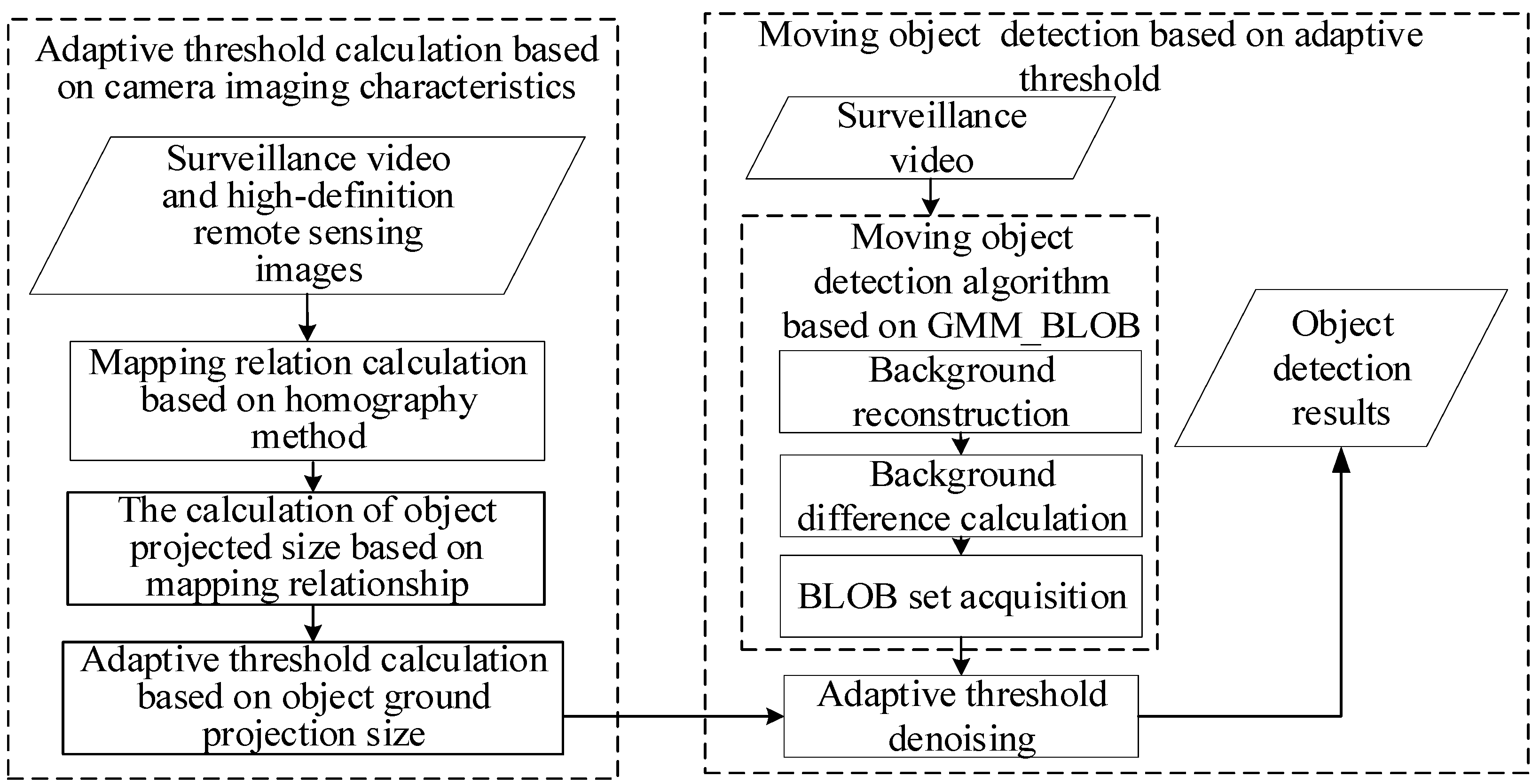
3.1. General Idea and Technical Process
- Adaptive threshold calculation based on camera-imaging characteristics
- 2.
- Moving object detection based on adaptive threshold
3.2. Adaptive Threshold Calculation Based on Camera Perspective Characteristics
3.2.1. Mapping Relation Calculation Based on Homography Method
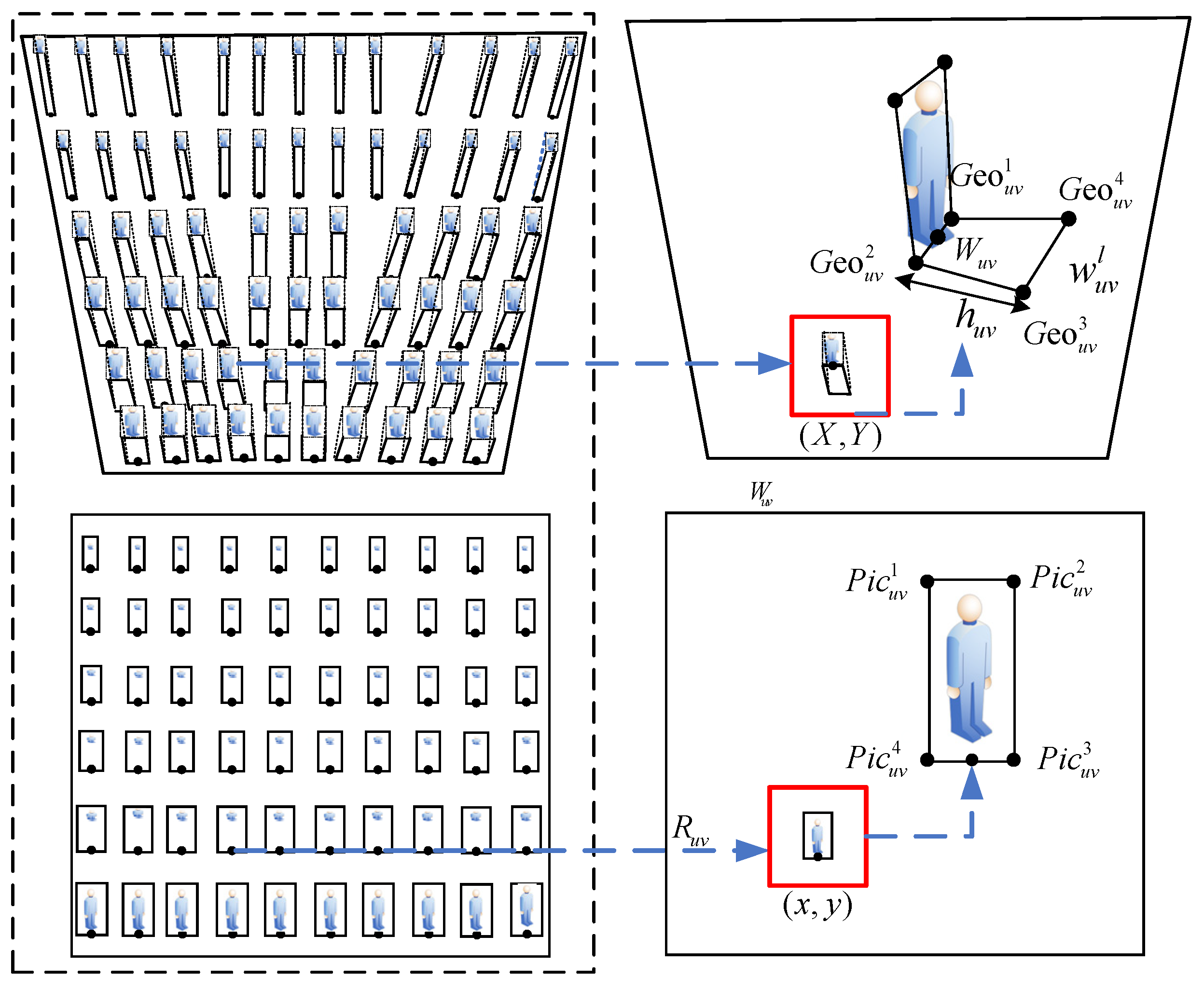
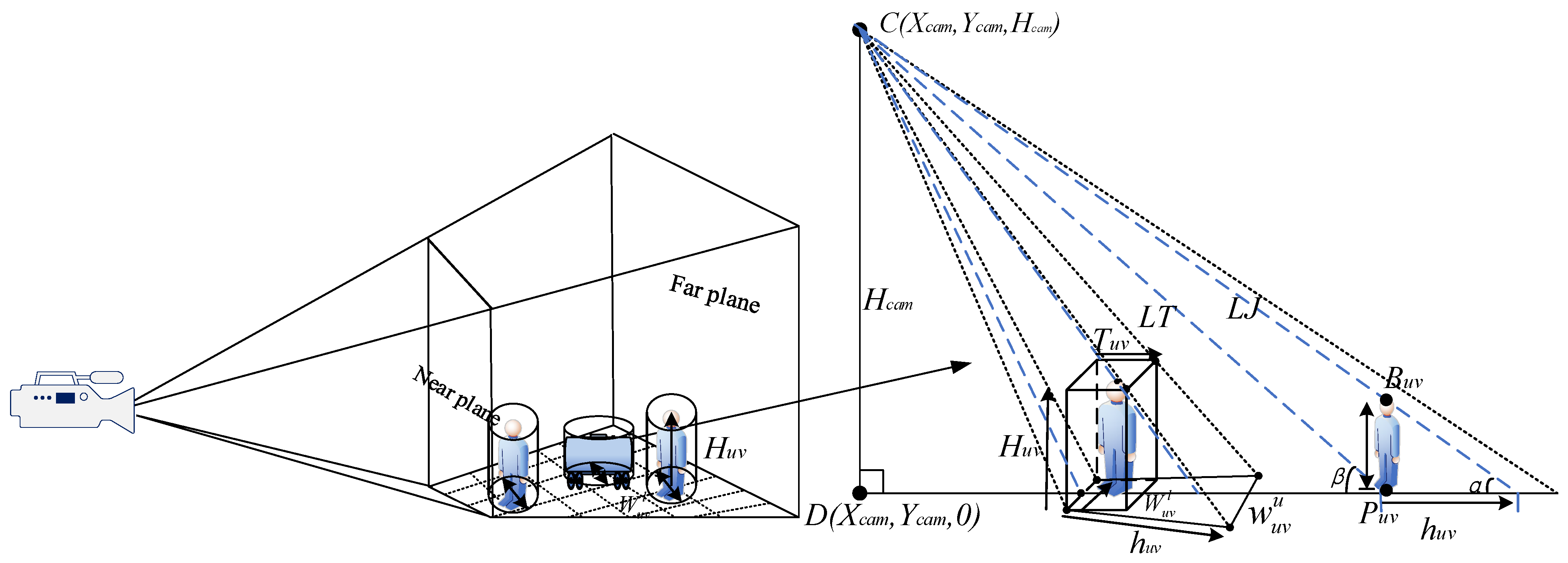
3.2.2. Calculation of Object Projected Size Based on Mapping Relationship
- Calculation of the object’s projected length, , in ground
- 2.
- Calculation of the object’s projected length, , in ground
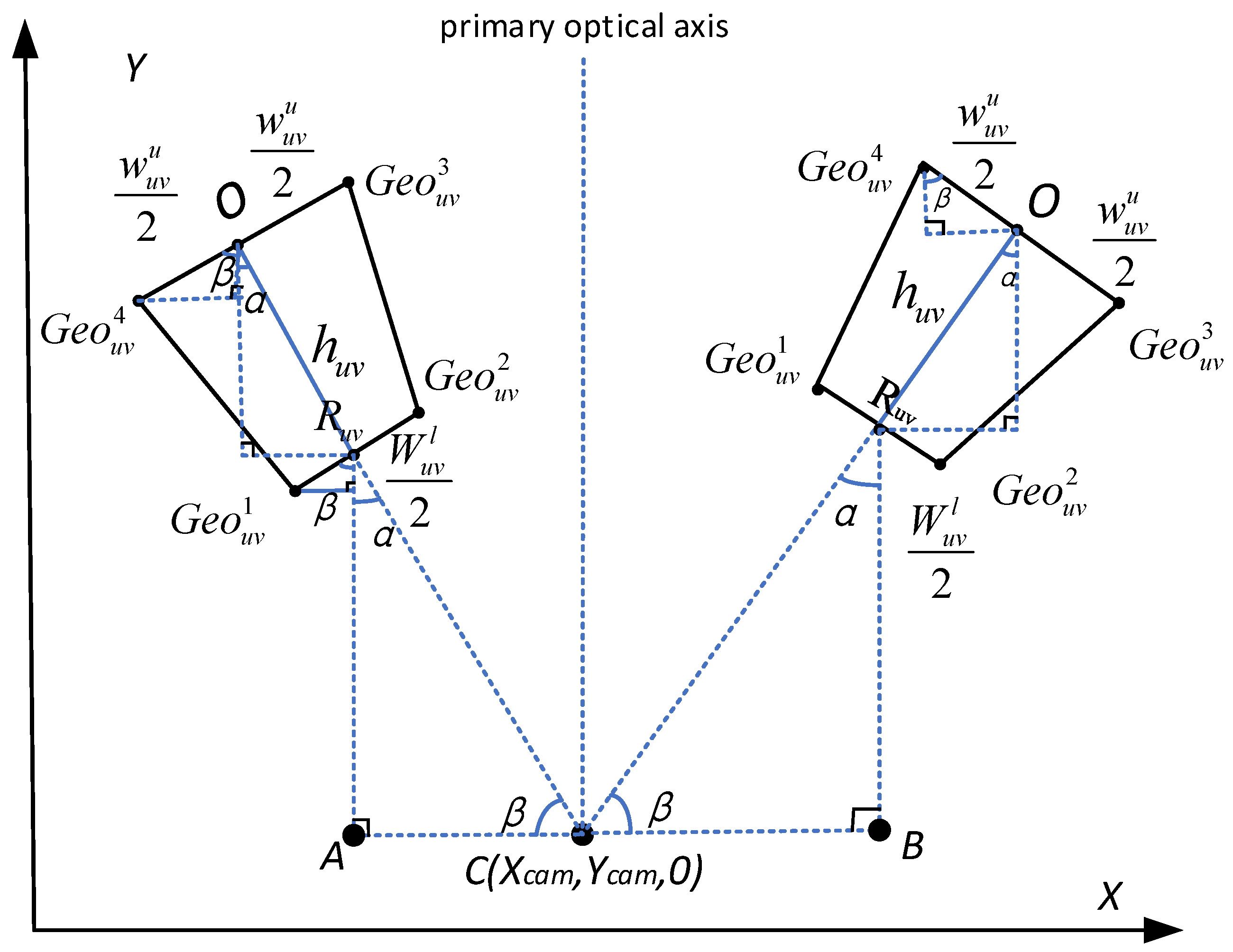
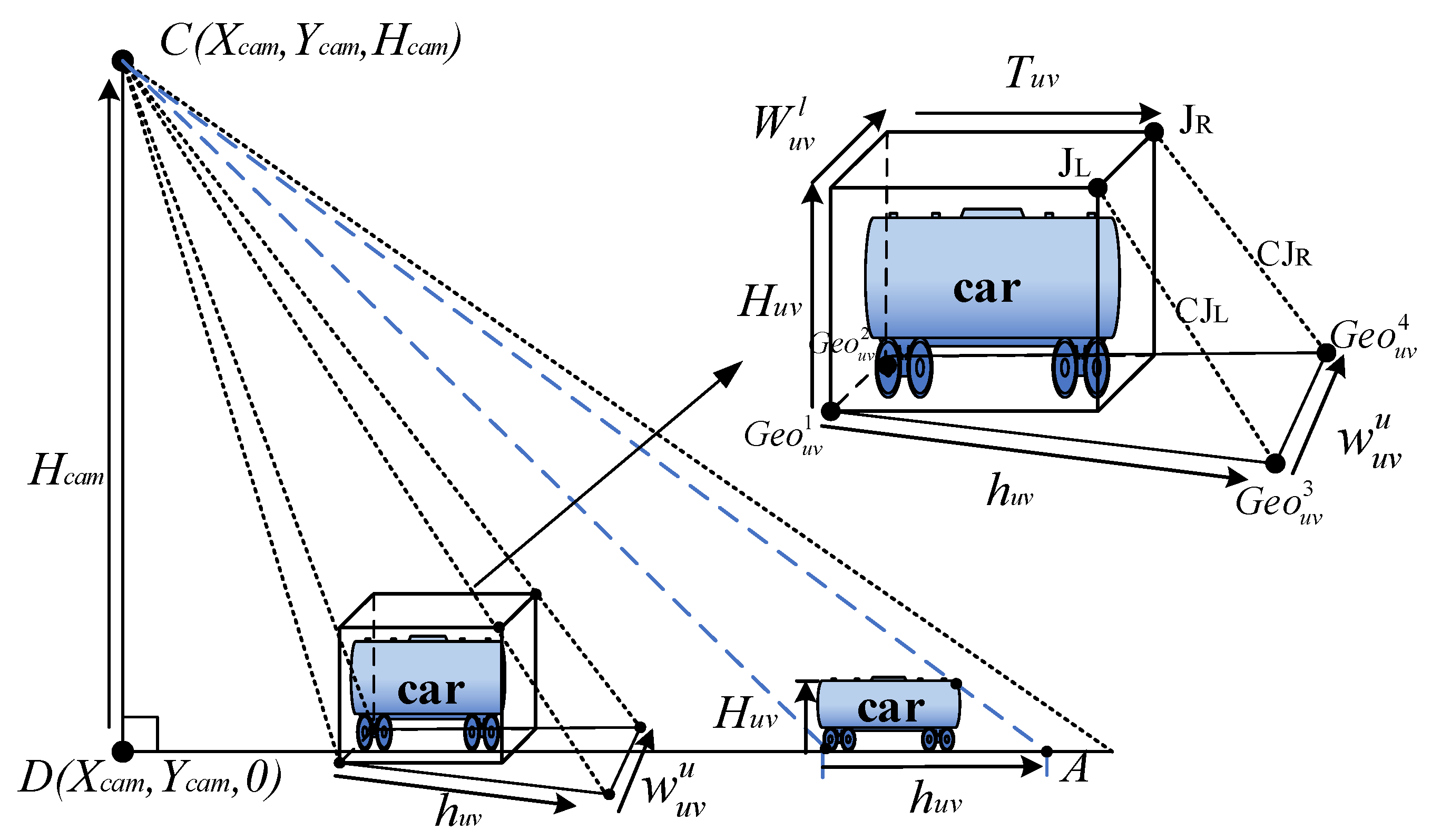
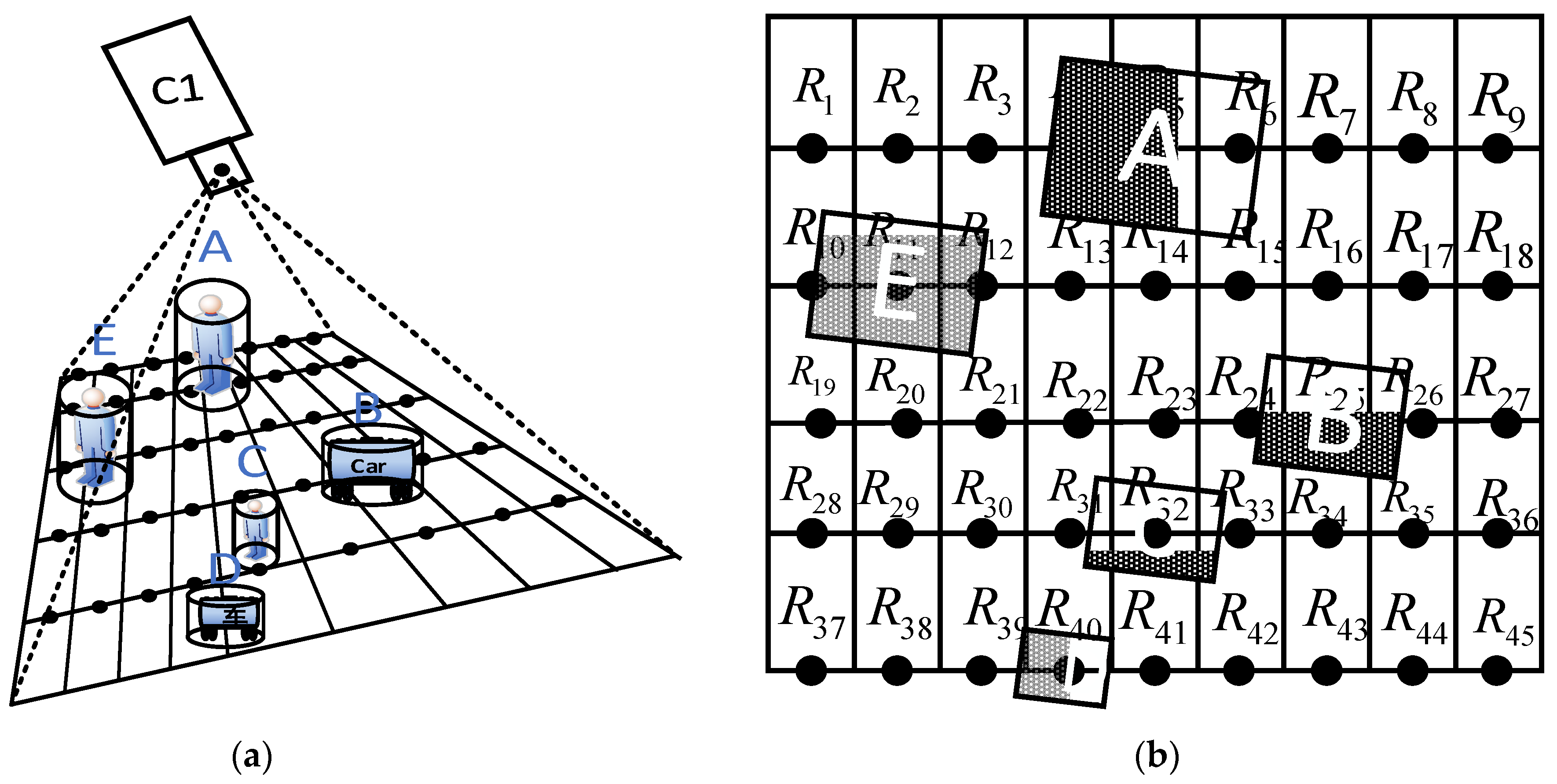
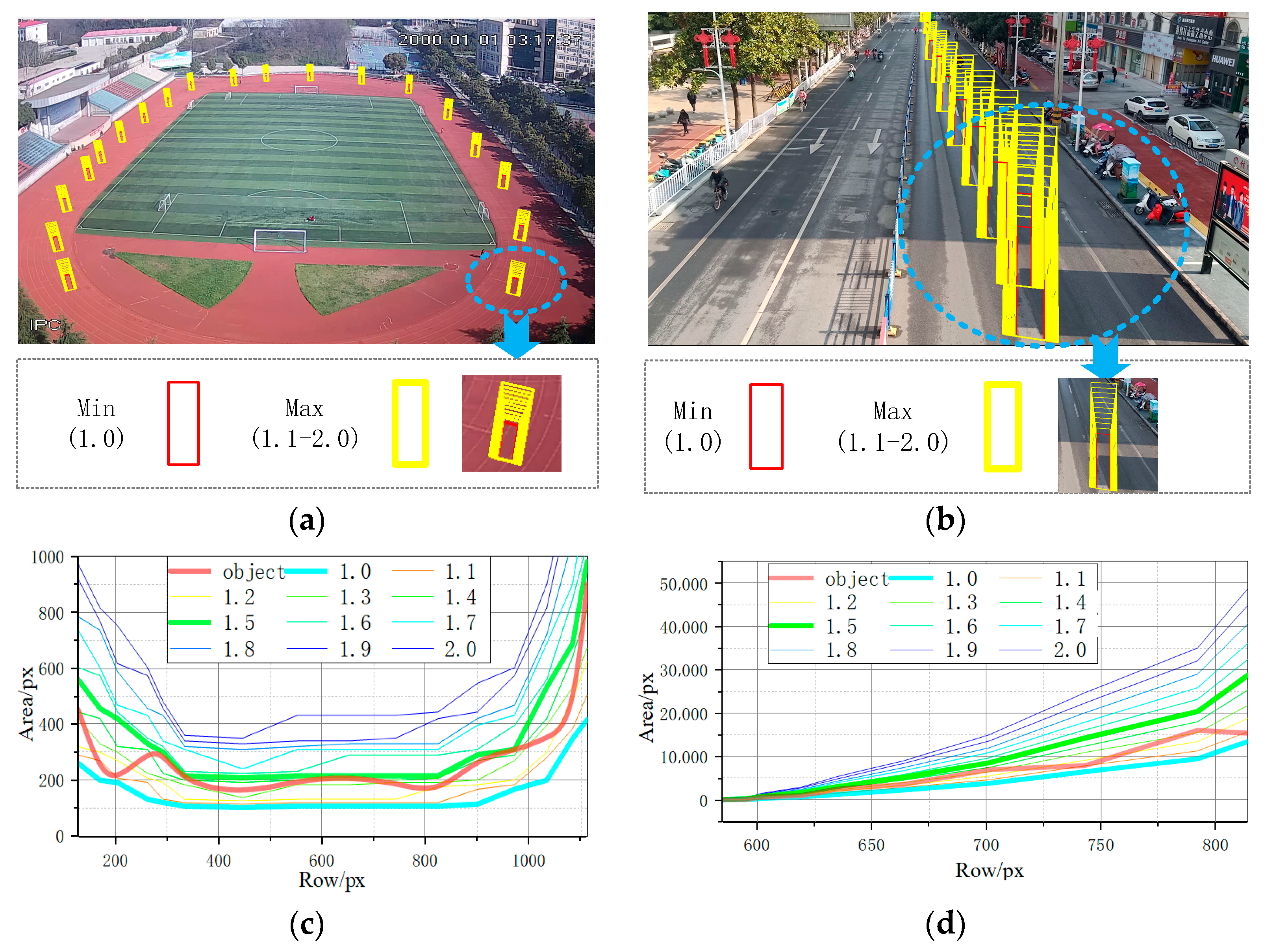
3.2.3. Adaptive Threshold Calculation Based on Object-Ground Projection Size
- Calculation of the quadrilateral coordinates of the object projected to the ground
- 2.
- Calculation of the area range of the object in the image plane
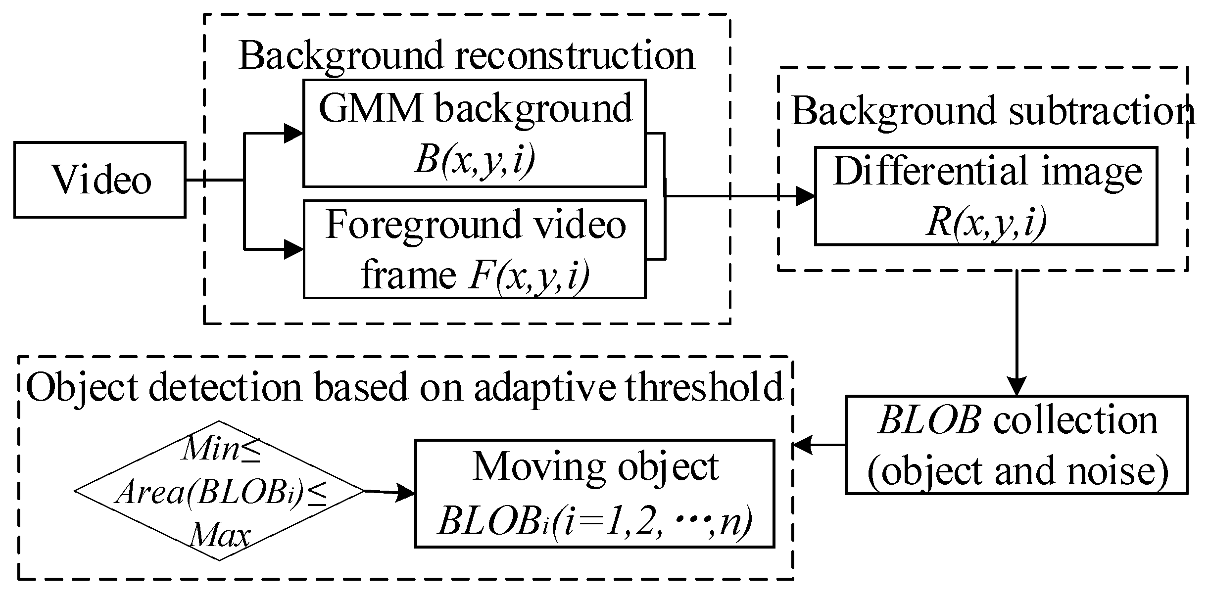
3.3. Moving Object Detection Based on Adaptive Threshold
3.3.1. Adaptive Threshold Calculation and Application
3.3.2. Moving Object Detection Based on GMM_BLOB Algorithm
4. Experimental Test
4.1. Experimental Design
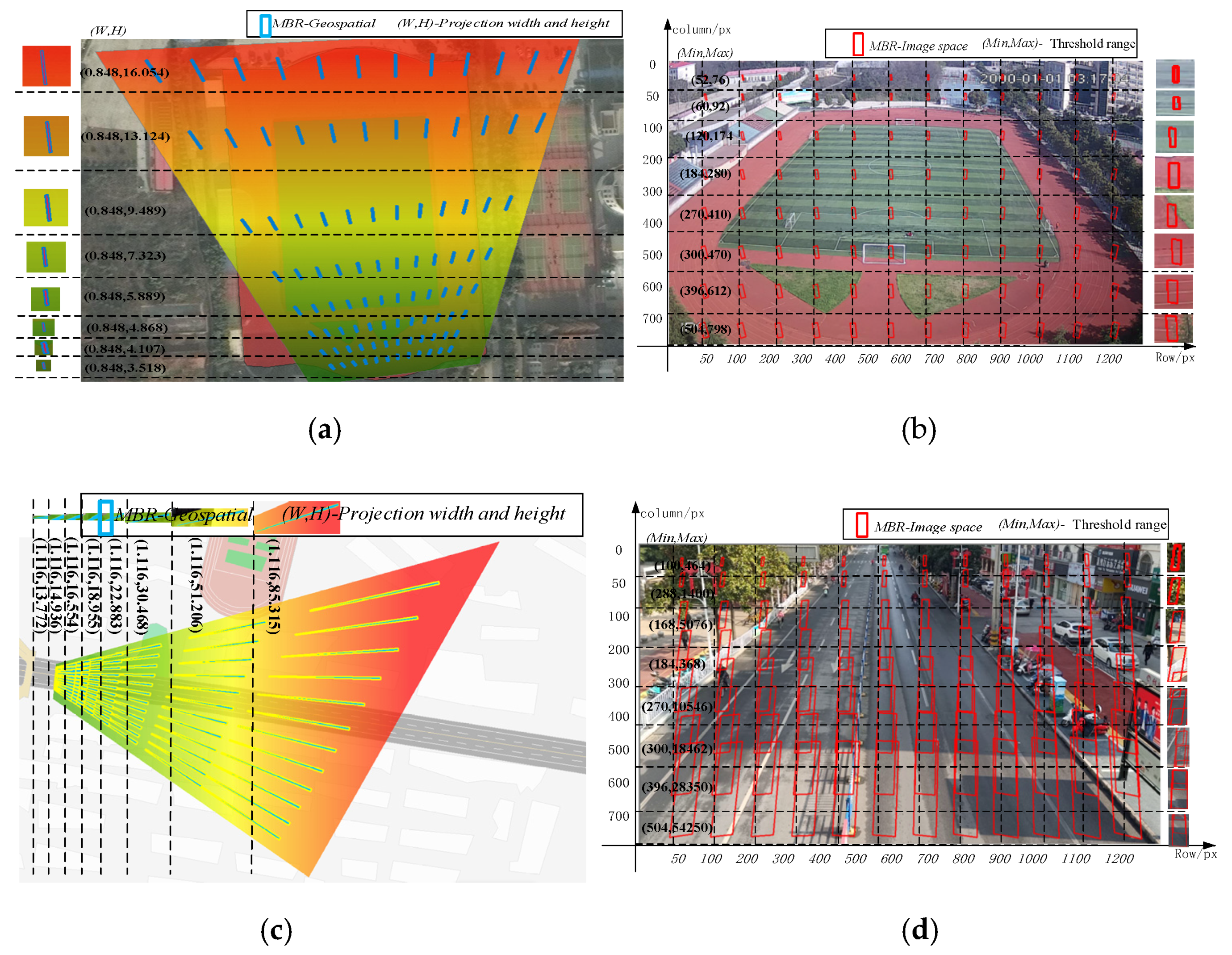
4.2. Adaptive Threshold Calculation
4.3. Single-Frame Accuracy Verification
- The mean value of object detection error (MD) is reduced by 1.2–6.8% for video #1 and by 1.65–11.05% for video #2.
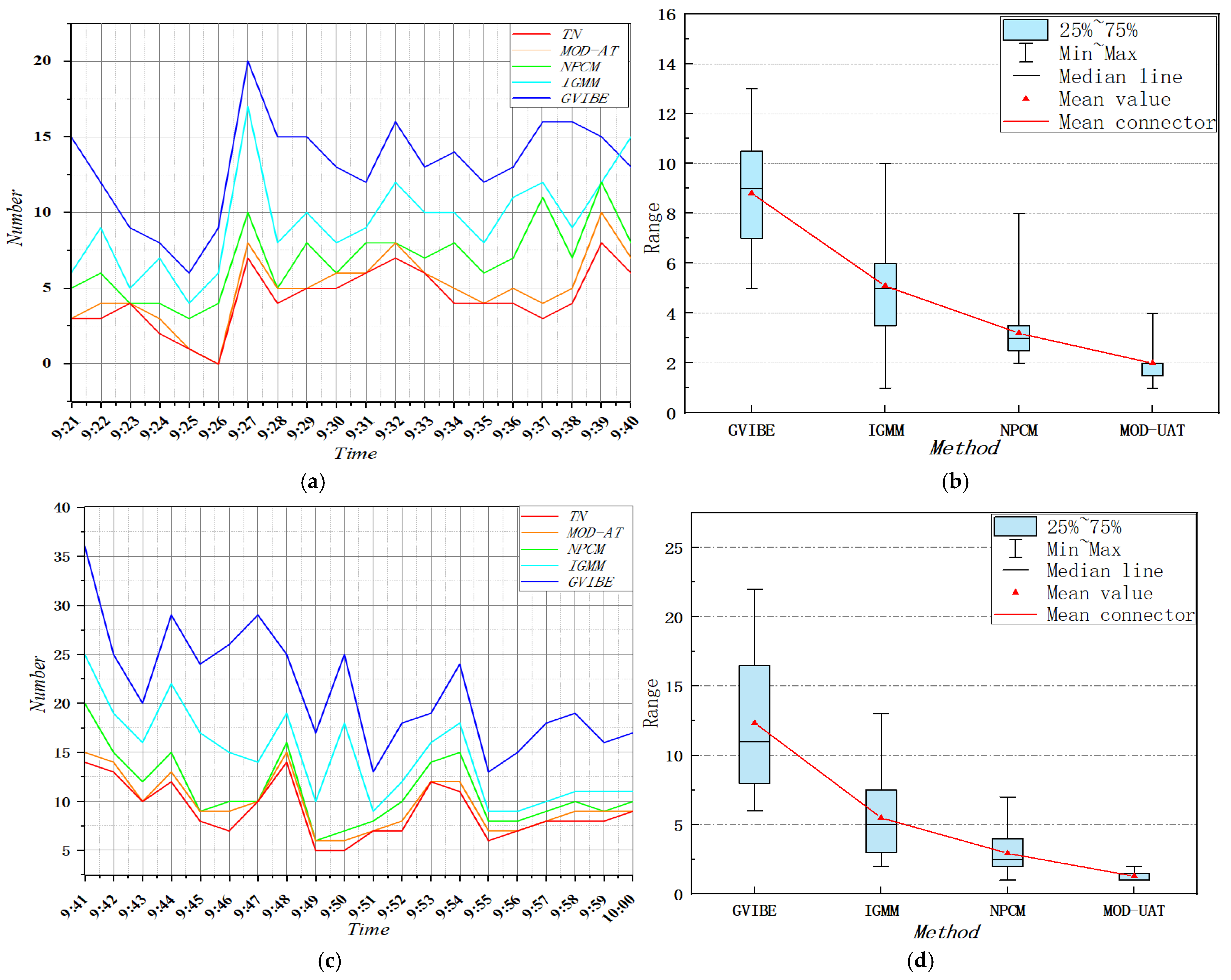
- The MN of MOD-AT object detection results for videos #1 and #2 decreases by 1.5–10.5% and 1–15.5%, respectively, on the whole; by 3.5–5% and 3–6.5%, respectively, compared with the IGMM algorithm; by 7–10.5% and 8–15.5%, respectively, compared with the GVIBE algorithm; and by 1.5–2% and 1–1.5%, respectively, compared with the NPCM algorithm. As shown in the randomly selected time points in Table 4, it can be seen that the precision, recall, and F1 score of the MOD-AT algorithm for single-frame detection are all higher than those of the GVIBE, IGMM, NPCM, and MOD-AT, indicating that the MOD-AT algorithm has high precision.

4.4. Verification of Overall Accuracy
5. Conclusions and Discussion
- Compared with the existing object detection algorithm, the median error (MD) of the MOD-AT algorithm is reduced by 1.2–11.05%.
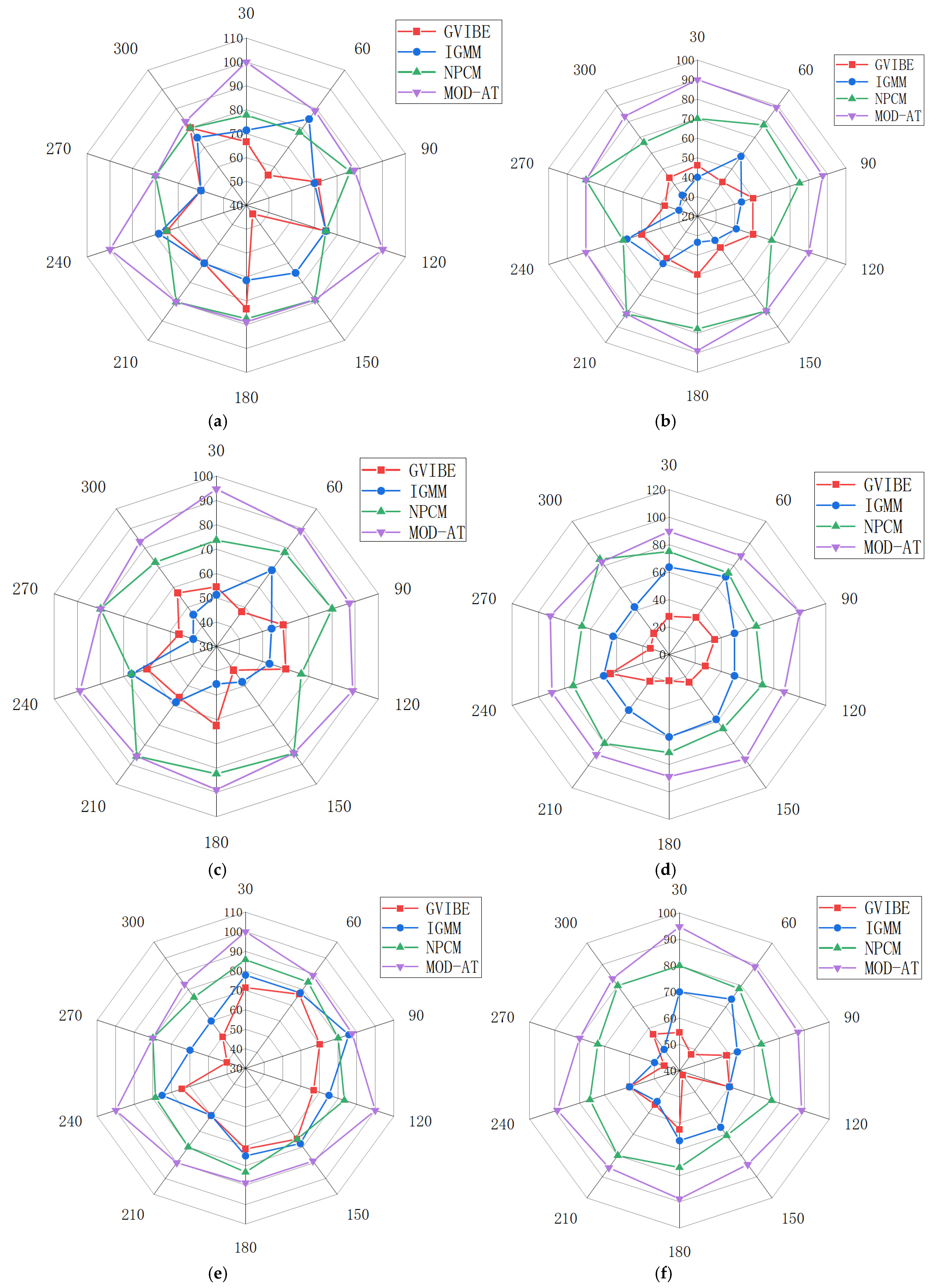
- The mean error (MN) of the MOD-AT object detection results is reduced by 1–15.5%, which shows that the MOD-AT algorithm has high accuracy in single-frame detection. In terms of overall accuracy, (a) the results show that the F1 score of the MOD-AT algorithm is above 90% for different experimental scenarios, demonstrating the stability of the MOD-AT algorithm; and (b) compared with the existing object detection algorithms, the MOD-AT algorithm improves MP by 17.13–44.4%, MR by 7.98–24.38%, and MF by 10.13–33.97%, which shows that the MOD-AT algorithm has high precision.
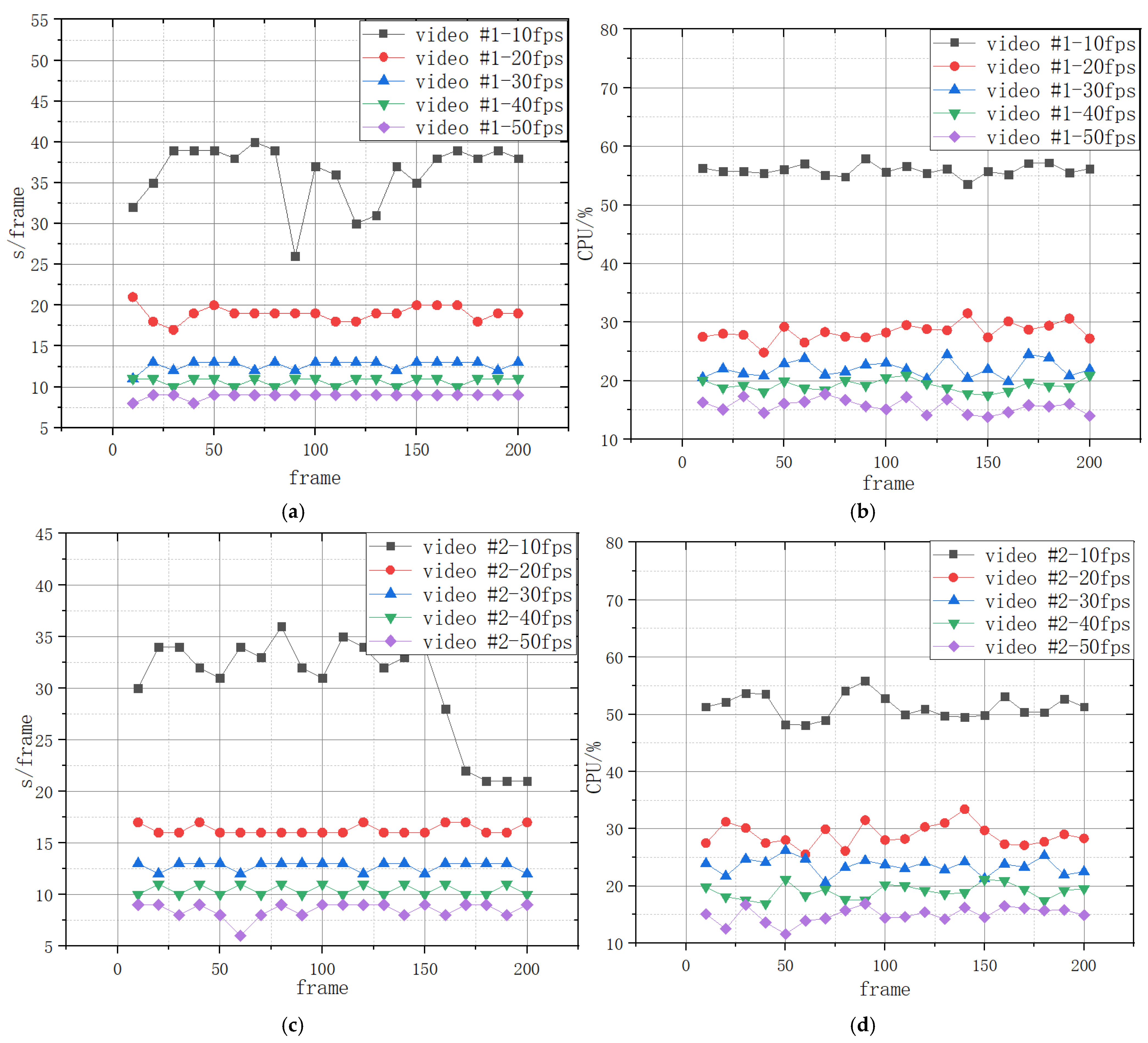
- The MOD-AT algorithm performance was improved by 7.9–24.3% compared to other algorithms, reflecting its efficiency.
Author Contributions
Funding
Institutional Review Board Statement
Informed Consent Statement
Data Availability Statement
Acknowledgments
Conflicts of Interest
References
- Yong, W.W. Video Specialization Method and Its Application. J. Nanjing Norm. Univ. 2014, 37, 119–125. [Google Scholar]
- Du, B.; Zhang, L. Target detection based on a dynamic subspace. Pattern Recognit. 2014, 47, 344–358. [Google Scholar] [CrossRef]
- Cheng, B.; Zhao, C. A new anomaly target detection algorithm for hyperspectral imagery based on optimal band subspaces. J. Appl. Sci. Eng. 2020, 23, 213–224. [Google Scholar]
- Sun, W.; Du, H.; Ma, G.; Shi, S.S.; Zhang, X.R.; Wu, Y. Moving vehicle video detection combining Vibe and inter-frame difference. Int. J. Embed. Syst. 2020, 12, 371–379. [Google Scholar] [CrossRef]
- Bouwmans, T. Traditional and recent approaches in background modeling for foreground detection: An overview. J. Comput. Sci. Rev. 2014, 11, 31–66. [Google Scholar] [CrossRef]
- Zhang, X.G.; Liu, X.J.; Song, H.Q. Video surveillance GIS: A novel application. In Proceedings of the 21st International Conference on Geoinformatics, Kaifeng, China, 20–22 June 2013. [Google Scholar]
- Li, X.P.; Lei, S.Z.; Zhang, B.; Yanhong, W.; Feng, X. Fast aerial ova detection using improved inter-frame difference and svm. J. Phys. Conf. Ser. 2019, 1187, 032082. [Google Scholar]
- Song, H.Q.; Liu, X.J.; Lv, G.N.; Zhang, X.G.; Feng, W. Video scene invariant crowd density estimation using geographic information systems. J. China Commun. 2014, 11, 80–89. [Google Scholar]
- Shao, Z.; Li, C.; Li, D.; Orhan, A.; Lei, Z.; Lin, D. An accurate matching method for projecting vector data into surveillance video to monitor and protect cultivated land. ISPRS Int. J. Geo. Inf. 2020, 9, 448. [Google Scholar] [CrossRef]
- Amrutha, C.V.; Jyotsna, C.; Amudha, J. Deep learning approach for suspicious activity detection from surveillance video. In Proceedings of the 2020 2nd International Conference on Innovative Mechanisms for Industry Applications (ICIMIA), Bangalore, India, 5–7 March 2020; IEEE: Piscataway, NJ, USA, 2020; pp. 335–339. [Google Scholar]
- Elharrouss, O.; Almaadeed, N.; Al-Maadeed, S.; Bouridane, A.; Beghdadi, A. A combined multiple action recognition and summarization for surveillance video sequences. Appl. Intell. 2021, 51, 690–712. [Google Scholar] [CrossRef]
- French, G.; Mackiewicz, M.; Fisher, M.; Holah, H.; Kilburn, R.; Campbell, N.; Needle, C. Deep neural networks for analysis of fisheries surveillance video and automated monitoring of fish discards. ICES J. Mar. Sci. 2020, 77, 1340–1353. [Google Scholar] [CrossRef]
- Balasundaram, A.; Chellappan, C. An intelligent video analytics model for abnormal event detection in online surveillance video. J. Real Time Image Process. 2020, 17, 915–930. [Google Scholar] [CrossRef]
- Gracewell, J.; John, M. Dynamic background modeling using deep learning auto encoder network. Multimed. Tools Appl. 2020, 79, 4639–4659. [Google Scholar] [CrossRef]
- Qin, W.; Zhu, X.L.; Xiao, Y.P.; Yan, J. An Improved Non-Parametric Method for Multiple Moving Objects Detection in the Markov Random Field. Comput. Model. Eng. Sci. 2020, 124, 129–149. [Google Scholar]
- Singla, N. Motion detection based on frame difference method. Int. J. Inf. Comput. Technol. 2014, 4, 1559–1565. [Google Scholar]
- Colque, R.V.H.M.; Caetano, C.; Andrade, M.T.L.; Schwartz, W.R. Histograms of optical flow orientation and magnitude and entropy to detect anomalous events in videos. IEEE Trans. Circuits Syst. Video Technol. 2016, 27, 673–682. [Google Scholar] [CrossRef]
- Gannakeris, P.; Kaltsa, V.; Avgerinakis, K.; Briassouli, A.; Vrochidis, S.; Kompatsiaris, I. Speed estimation and abnormality detection from surveillance cameras. In Proceedings of the IEEE Conference on Computer Vision and Pattern Recognition Workshops, Salt Lake City, UT, USA, 18–22 June 2018; IEEE: Piscataway, NJ, USA, 2018; pp. 93–99. [Google Scholar]
- Liu, H.B.; Chang, F.L. Moving object detection by optical flow method based on adaptive weight coefficient. Opt. Precis. Eng. 2016, 24, 460–468. [Google Scholar]
- Fan, L.; Zhang, T.; Du, W. Optical-flow-based framework to boost video object detection performance with object enhancement. Expert Syst. Appl. 2020, 170, 114544. [Google Scholar] [CrossRef]
- Xing, X.; Yong, J.Y.; Huang, X. Real-Time Object Tracking Based on Optical Flow. In Proceedings of the 2021 International Conference on Computer, Control and Robotics (ICCCR), Shanghai, China, 8–10 January 2021; IEEE: Piscataway, NJ, USA, 2021; pp. 315–318. [Google Scholar]
- Wu, B.; Wang, C.; Huang, W.; Huang, P. Recognition of Student Classroom Behaviors Based on Moving Target Detection. J. Treat. Signal 2021, 38, 215–220. [Google Scholar]
- Li, X.; Zheng, H. Target detection algorithm for dance moving images based on sensor and motion capture data. Microprocess. Microsyst. 2021, 81, 103743. [Google Scholar] [CrossRef]
- Zuo, J.H.; Jia, Z.H.; Yang, J.; Nikola, K. Moving object detection in video image based on improved background subtraction. Comput. Eng. Des. 2020, 41, 1367–1372. [Google Scholar]
- Luo, M.; Liu, D.B.; Wen, H.X.; Chen, X.T.; Song, D. A New Vehicle Moving Detection Method Based on Background Difference and Frame Difference. J. Hunan Inst. Eng. 2019, 29, 58–61. [Google Scholar]
- Akhter, I.; Jalal, A.; Kim, K. Pose estimation and detection for event recognition using sense-aware features and Adaboost classifier. In Proceedings of the 2021 International Bhurban Conference on Applied Sciences and Technologies (IBCAST), Islamabad, Pakistan, 12–16 January 2021; IEEE: Piscataway, NJ, USA, 2021; pp. 500–505. [Google Scholar]
- Li, Y.; Wu, J.; Bai, X.; Yang, X.; Tan, X.; Li, G.; Zhang, H.; Ding, E. Multi-granularity tracking with modularlized components for unsupervised vehicles anomaly detection. In Proceedings of the IEEE/CVF Conference on Computer Vision and Pattern Recognition Workshops, Seattle, WA, USA, 14–19 June 2020; IEEE: Piscataway, NJ, USA, 2020; pp. 586–587. [Google Scholar]
- Liu, Z.L.; Wu, Y.Q.; Zou, Y. Multiscale infrared superpixel-image model for small-target detection. J. Image Graph. 2019, 24, 2159–2173. [Google Scholar]
- Xin, Y.X.; Shi, P.F.; Xue, Y.Y. Moving Object Detection Based on Region Extraction and Improved LBP Features. Comput. Sci. 2021, 48, 233–237. [Google Scholar]
- Heikkilä, M.; Pietikäinen, M.A. Texture-Based Method for Modeling the Background and Detecting Moving Objects. IEEE Trans Pattern Anal. Mach. Intell. 2006, 28, 415–423. [Google Scholar] [CrossRef] [Green Version]
- Kong, G. Moving Object Detection Using a Cross Correlation between a Short Accumulated Histogram and a Long Accumulated Histogram. In Proceedings of the IEEE 18th International Conference on Pattern Recognition (ICPR’06), Hong Kong, China, 20–24 August 2006; pp. 896–899. [Google Scholar]
- Luo, D. Texture Analysis for Shadow Removing and Tracking of Vehicle in Traffic Monitoring System. In Proceedings of the 2008 International Symposium on Intelligent Information Technology Application Workshops, Shanghai, China, 21–22 December 2008; pp. 863–866. [Google Scholar]
- Liu, W.; Hao, X.L.; Lv, J.L. Efficient moving targets detection based on adaptive Gaussian mixture modelling. J. Image Graph. 2020, 25, 113–125. [Google Scholar]
- Zuo, J.; Jia, Z.; Yang, J.; Kasabov, N. Moving Target Detection Based on Improved Gaussian Mixture Background Subtraction in Video Images. IEEE Access 2019, 29, 152612–152623. [Google Scholar] [CrossRef]
- Zhang, X.G.; Liu, X.J.; Wang, S.N.; Liu, Y. Mutual Mapping between Surveillance Video and 2D Geospatial Data. Geomat. Inf. Sci. Wuhan Univ. 2015, 40, 1130–1136. [Google Scholar]
- Chan, A.B.; Liang, Z.-S.J.; Vasconcelos, N. Privacy preserving crowd monitoring: Counting people without people models or tracking. In Proceedings of the 2008 IEEE Conference on Computer Vision and Pattern Recognition, Anchorage, AK, USA, 23–28 June 2008; IEEE: Piscataway, NJ, USA, 2008; pp. 1–7. [Google Scholar]
- Chang, Q.L.; Xia, H.S.; Li, N. A Method for People Counting in Complex Scenes Based on Normalized Foreground and Corner Information. J. Electron. Inf. Tech. 2014, 36, 312–317. [Google Scholar]
- Lin, B.X.; Xu, C.H.; Lan, X.; Zhou, L. A method of perspective normalization for video images based on map data. Ann. GIS 2020, 26, 35–47. [Google Scholar] [CrossRef]
- Xie, Y.; Wang, M.; Liu, X.; Mao, B.; Wang, F. Integration of Multi-Camera Video Moving Objects and GIS. ISPRS Int. J. Geo. Inf. 2020, 8, 561. [Google Scholar] [CrossRef] [Green Version]
- Sun, W.; Chen, S.; Shi, L.; Li, Y.; Lin, Z. Vehicle Following in Intelligent Multi-Vehicle Systems Based on SSD-MobileNet. In Proceedings of the Chinese Automation Congress (CAC), Hangzhou, China, 22–24 November 2019; IEEE: Piscataway, NJ, USA, 2019; pp. 5004–5009. [Google Scholar]
- Chen, L.; Zhang, R.G.; Hu, J.; Liu, K. Improved Gaussian Mixture Model and Shadow Elimination Method. J. Comput. Appl. 2013, 33, 1394–1400. [Google Scholar] [CrossRef]
- Zhang, L.; Shi, L.; Zhang, L. Adaptive threshold moving target detection algorithm based on Vibe. Comput. Inf. Technol. 2021, 29, 12–15. [Google Scholar]
- Zhu, S.F.; Yang, F.; Ma, W. Difference Method Target Detection Algorithm Based on Vibe Model and Five-Frame. Comput. Digit. Eng. 2020, 48, 667–670. [Google Scholar]
- Liu, Y.Z.; Zhang, H.B.; Yang, J.; Tang, T.G.; Tan, H.Y. A new algorithm of moving target tracking and detection based on optical flow techniques with frame difference methods. Electron. Des. Eng. 2021, 29, 139–144. [Google Scholar]
- Xiao, Y.Q.; Yang, H.M. Research on Application of Object Detection Algorithm in Traffic Scene. Comput. Eng. Appl. 2021, 57, 30–41. [Google Scholar]
- Barata, C.; Nascimento, J.C.; Marques, J.S. Multiple agent’s representation using motion fields. In Proceedings of the IEEE International Conference on Acoustics Speech and Signal Processing (ICASSP), Brighton, UK, 12–17 May 2019; IEEE: Piscataway, NJ, USA, 2019; pp. 2007–2011. [Google Scholar]
- Li, X.; Yang, Y.; Xu, Y.M. Detection of moving targets by four-frame difference in modified Gaussian mixture Model. Sci. Technol. Eng. 2020, 20, 6141–6150. [Google Scholar]
- Xie, Y.J.; Wang, M.Z.; Liu, X.J.; Wang, Z.; Mao, B.; Wang, F.; Wang, X. Spatiotemporal retrieval of dynamic video object trajectories in geographical scenes. Trans. GIS 2020, 25, 450–467. [Google Scholar] [CrossRef]
- Yang, X.; Li, F.; Lu, M. Moving Object Detection Method of Video Satellite Based on Tracking Correction Detection. ISPRS Ann. Photogramm. Remote Sens. Spat. Inf. Sci. 2020, 3, 701–707. [Google Scholar] [CrossRef]
- Yao, P.; Zhao, Z. Improved Glasius bio-inspired neural network for target search by multi-agents. Inf. Sci. 2021, 568, 40–53. [Google Scholar] [CrossRef]


| Camera Name | X (m) | Y (m) | Altitude (m) | Video Length (min) | Video Resolution (pix) | Location and FOV |
|---|---|---|---|---|---|---|
| video #1 | 3,781,008.991 | 12,694,007.489 | 30 m | 20 | 1280*720 | 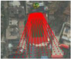 |
| video #2 | 3,779,585.151 | 12,698,259.888 | 6 m | 20 | 1280*720 | 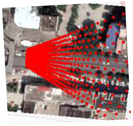 |
| Camera Name | Row (j) | Column (j) | Object Projection Width (m) | Object Projection Height (m) | Image Space Object Area (Number of Pixels) | Threshold Minimum (Number of Pixels) | Threshold Maximum (Number of Pixels) |
|---|---|---|---|---|---|---|---|
| video #1 | 527 | 21 | 1.13 | 5.17 | 60 | 60 | 299 |
| 451 | 111 | 1.13 | 3.81 | 410 | 410 | 2013 | |
| 372 | 288 | 1.13 | 1.73 | 2185 | 2185 | 10,425 | |
| 248 | 422 | 1.13 | 1.25 | 4455 | 4455 | 20,544 | |
| 154 | 476 | 1.13 | 1.14 | 5624 | 5624 | 25,680 | |
| video #2 | 338 | 56 | 0.85 | 1.46 | 56 | 56 | 80 |
| 276 | 148 | 0.85 | 1.06 | 108 | 108 | 156 | |
| 158 | 278 | 0.85 | 0.76 | 184 | 184 | 272 | |
| 54 | 370 | 0.85 | 0.64 | 208 | 208 | 312 | |
| 16 | 680 | 0.85 | 0.38 | 490 | 490 | 784 |
| Video Time | Video #1 | Video #2 | ||
|---|---|---|---|---|
| 9:21 | 9:22 | 9:41 | 9:42 | |
| Video frame |  |  | 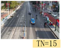 | 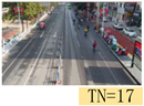 |
| Background |  |  |  |  |
| GVIBE |  |  |  | 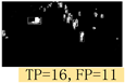 |
| IGMM | 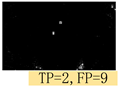 | 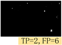 |  | 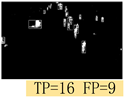 |
| NPCM | 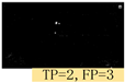 | 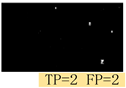 | 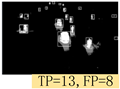 | 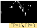 |
| MOD-AT | 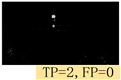 | 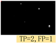 | 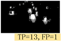 | 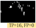 |
| Method Time | Video #1 | Video #2 | ||||
|---|---|---|---|---|---|---|
| Precision | Recall | F1_Score | Precision | Recall | F1_Score | |
| 9:20/9:30 | 9:40/9:50 | |||||
| GVIBE | 46.15/50 | 55.56/60 | 58.82/60 | 47.12/45 | 66.67/64.29 | 56/54.55 |
| IGMM | 40/57.89 | 77.78/71.43 | 68.75/53.85 | 58.33/60 | 75/77.78 | 63.23/63.16 |
| NPCM | 70/77.78 | 84.62/85.71 | 80/82.53 | 66.67/71.43 | 80/83.33 | 76.04/72.3 |
| MOD-AT | 90/89.9 | 96/87.5 | 87.50/85.71 | 90.91/89.66 | 90.23/90.89 | 88.89/94.74 |
| Method | Video #1 | Video #2 | ||||
|---|---|---|---|---|---|---|
| MP/VP | MR/VR | MF/VF | MP/VP | MR/VR | MF/VF | |
| GVIBE | 45.64/4.63 | 68.14/11.87 | 54.49/6.86 | 47.91/8.99 | 66.19/11.67 | 54.19/8.12 |
| IGMM | 42.24/10.1 | 73.11/6.41 | 53.14/9.22 | 54.98/8.92 | 73.78/9.10 | 62.75/6.86 |
| NPCM | 72.91/8.25 | 81.77/5.74 | 76.98/6.81 | 71.61/6.15 | 81.17/7.06 | 76.04/4.03 |
| MOD-AT | 90.04/4.29 | 89.75/4.06 | 87.11/4.03 | 91.13/4.32 | 90.57/3.73 | 87.52/3.42 |
Publisher’s Note: MDPI stays neutral with regard to jurisdictional claims in published maps and institutional affiliations. |
© 2021 by the authors. Licensee MDPI, Basel, Switzerland. This article is an open access article distributed under the terms and conditions of the Creative Commons Attribution (CC BY) license (https://creativecommons.org/licenses/by/4.0/).
Share and Cite
Luo, X.; Wang, Y.; Cai, B.; Li, Z. Moving Object Detection in Traffic Surveillance Video: New MOD-AT Method Based on Adaptive Threshold. ISPRS Int. J. Geo-Inf. 2021, 10, 742. https://doi.org/10.3390/ijgi10110742
Luo X, Wang Y, Cai B, Li Z. Moving Object Detection in Traffic Surveillance Video: New MOD-AT Method Based on Adaptive Threshold. ISPRS International Journal of Geo-Information. 2021; 10(11):742. https://doi.org/10.3390/ijgi10110742
Chicago/Turabian StyleLuo, Xiaoyue, Yanhui Wang, Benhe Cai, and Zhanxing Li. 2021. "Moving Object Detection in Traffic Surveillance Video: New MOD-AT Method Based on Adaptive Threshold" ISPRS International Journal of Geo-Information 10, no. 11: 742. https://doi.org/10.3390/ijgi10110742
APA StyleLuo, X., Wang, Y., Cai, B., & Li, Z. (2021). Moving Object Detection in Traffic Surveillance Video: New MOD-AT Method Based on Adaptive Threshold. ISPRS International Journal of Geo-Information, 10(11), 742. https://doi.org/10.3390/ijgi10110742