Article

A Safety Monitoring Model for a Faulty Mobile Robot

1
Department of Electrical and Computer Engineering, Faculty of Engineering, University of Porto, Rua Dr. Roberto Frias, 4200-465 Porto, Portugal
2
INESC TEC and Department of Electrical and Computer Engineering, Faculty of Engineering, University of Porto, Rua Dr. Roberto Frias, 4200-465 Porto, Portugal
*
Authors to whom correspondence should be addressed.
Robotics 2018, 7(3), 32; https://doi.org/10.3390/robotics7030032
Submission received: 30 April 2018 / Revised: 4 June 2018 / Accepted: 15 June 2018 / Published: 21 June 2018
(This article belongs to the Special Issue Robust and Resilient Robots)

Abstract

:
The continued development of mobile robots (MR) must be accompanied by an increase in robotics’ safety measures. Not only must MR be capable of detecting and diagnosing faults, they should also be capable of understanding when the dangers of a mission, to themselves and the surrounding environment, warrant the abandonment of their endeavors. Analysis of fault detection and diagnosis techniques helps shed light on the challenges of the robotic field, while also showing a lack of research in autonomous decision-making tools. This paper proposes a new skill-based architecture for mobile robots, together with a novel risk assessment and decision-making model to overcome the difficulties currently felt in autonomous robot design.

1. Introduction

Robotics can be seen as a scientific art, a branch of engineering that aims to develop automated tools that can mimic human ability to manipulate the environment. Such systems, to achieve this goal, require various components, which can be divided as: sensor, power source, actuators, controllers and a physical structure—a body that can house all these parts [1], akin to how the human body houses various organs, bones and muscles to allow the perceiving and manipulation of their surroundings. This path diverges into two distinct categories; robots might be used as tools (operated by humans) or they might be made to be capable of autonomous operation, going as far as to replace humans in some jobs. Nevertheless, replacement isn’t the only concern, the potential to completely surpass humanity is also worrying. The European Union Parliament ordered a study, published in 2017, that comes to these conclusions [2]. In an age where robots are becoming an important of our daily lives, it is important to find ways to assure they are reliable and safe.
One of the questions that arises with autonomous mobile robots, and therefore needs to be focused on, is how to keep them, operating with little to no human interaction, from causing damage to people or the surrounding environment? One possible solution is the use of a safety monitoring system, capable of defining when, given a mission, the robot has the necessary conditions to follow it through or when it should cancel the operation and, for example, return to base for repairs. For this decision to be correct though, it can’t be taken blindly. There must be knowledge of many variables, like the state of sensors, actuators, and the decision layer. This is where the importance of fault diagnosis arises, since it provides a means of both understanding when a fault occurs and what subsystem is affected [3].
“We need to build systems that will acknowledge the existence of faults as a fact of life” (Koren and Krishna, 2007) [4], not because we should allow system faults to remain unchecked, but because only the acceptance of their existence, and therefore of the systems’ weaknesses, will enable us to correctly investigate what causes these faults, what are their predictable consequences, what unpredictable consequences might exist. In short, recognizing the existence of the problem allows us to try and design tools and architectures that will prevent harm to the system, to the environment or, more importantly, to the people that interact, directly or indirectly, with the robotic system. It is also an important issue that faults can happen both in software or hardware. In fact, according to Guiochet et al., 2017 [5], software faults are more frequent. It can also be argued that, if a hardware fault goes undetected, the software that is working properly might be a cause of harm because of misinformation introduced in the decision process.
Civilization needs sets of rules to work properly, one of the reasons being that they are needed to try to guarantee people’s safety. The same has to apply to our technology, as evidenced by Nevejans, 2017 [2]. Among the various international standard organizations, ISO and IEC are of particular interest for the development of robotics. Founded in 1946, ISO claims to “facilitate the international coordination and unification of industrial standards”. IEC, founded in 1906, emphasizes that “millions of devices that contain electronics, and use or produce electricity, rely on IEC International Standards and Conformity Assessment Systems to perform, fit and work safely together”. Both organizations have standing agreements with the EU own standard organization, CENELEC, that give precedence to the work developed at ISO (Vienna Agreement [6]) and IEC (Frankfurt Agreement [7]). The IEC 61508 standard is a good basis for a set of rules to govern the field of robotics because, although thought as a generalization to “all industry sectors”, it was meant to work as a draft for future works aimed at specific sectors and it is already being accepted by “safety equipment suppliers and users” [8].
Saying it is a good basis, however, does not mean to accept blindly every single principle or recommendation. As IEC 61511, for example, is a standard that implements IEC 61508 in a process industry context [9], it is not farfetched to believe that other standards will continue to appear to specifically address the various fields of engineering. Especially considering that, even though development of fault detection and fault diagnosis has been traced back to the early 1970s [10], there are still accidents with industrial robots or, in more recent projects of autonomous mobile robots—a fatal accident occurred involving a self-driving car test [5].
Despite the importance of the IEC 61508 standard, literature based on it seems to indicate a much higher concern with the average probability failure of components or with the probability that a failure will result in a safe state [8,11]. In this work, however, the main concern is what to do when a fault occurs. The questions that need answering are not, “How likely is a fault to occur?”, but rather, “What decision should be taken, now that a fault has occurred or has been detected?” This decision cannot be taken lightly. How potentially dangerous is the mission? How much of that risk is directed towards the robot, the environment or the people? Is the mission critical enough that the cost of a lost robot is acceptable? What role does the faulty component play? Is the fault permanent or transient? All these questions might need to be considered when an operator makes such a decision. When a system is either designed or adapted to decide on its own, the same questions may need to be considered. Although it is not an easy task to fully develop a universally applicable solution, this research aims to be a general guide for the creation of a safety oriented decision-making model by proposing:
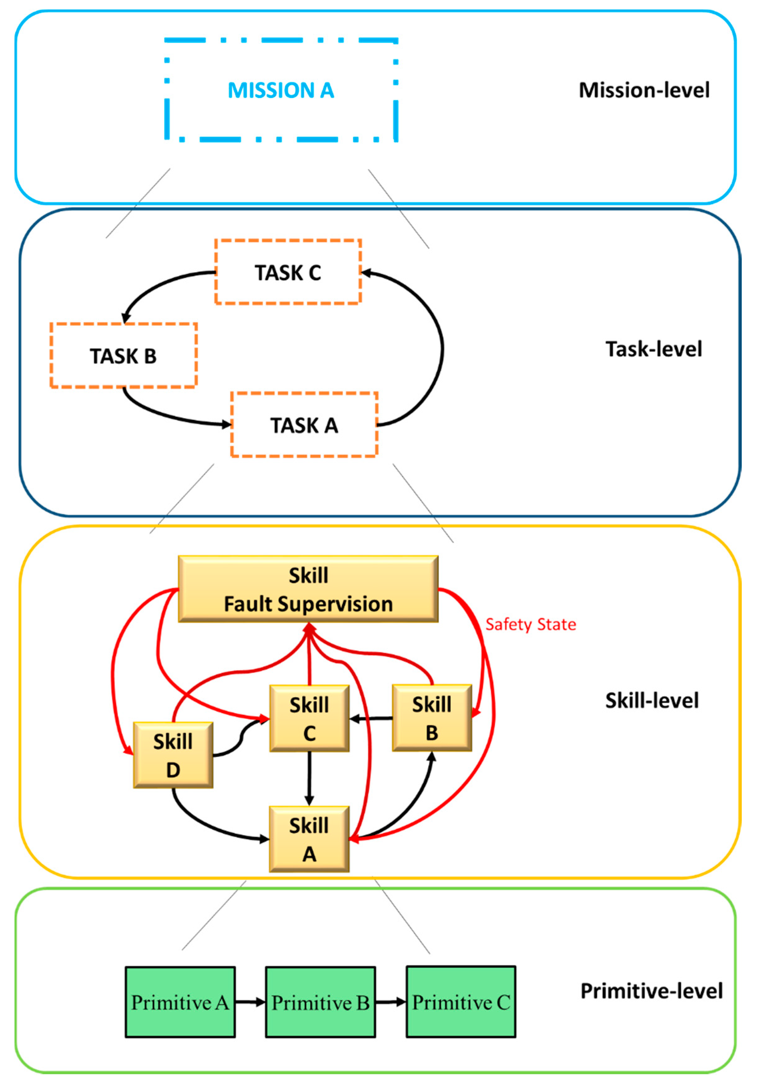
  • Skills Architecture: capable of building highly complex operations by a systematic aggregation of low complexity blocks, using the concept of primitives, skills and tasks.
  • Safety Monitoring Model: using a mathematical function to determine the risk using the safety state, which is defined by the fault processes affecting the skill.
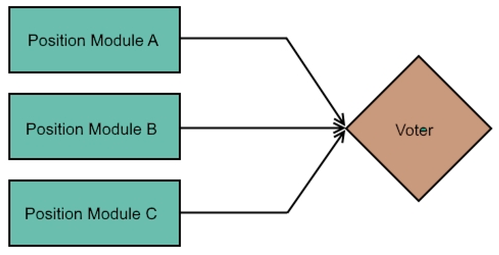
  • Decision-making Model: which will receive the risk evaluation as an input and classify the situation, and therefore decide the action to take, as an output.
The rest of the manuscript is organized as follows: Section 2 provides an overview of current advances in safety measures, especially fault detection and diagnosis. Section 3 presents system architecture, risk assessment and decision-making models. Section 4 exemplifies how to apply the presented model on a real system. Section 5 concludes this manuscript.

2. State-of-The-Art

Research on fault diagnosis and fault tolerance directed at mobile robots is a recent development. Most literature on this subject is from 2010 and, although some research and mentions to mobile robots can be found in earlier years, there is none earlier than the year 2000. Prior research exists, however, on safety and reliability of engineering systems. Despite the lack of literature concerning strategies aiming at fault tolerance, monitoring, and supervision of the decision layer, research into hardware strategies can be used as a source of reliable introduction to safety features in robotics.

2.1. Overview

Both in [10] and [12] we can find compilations of some developments in fault diagnosis. Through analysis of these works, it becomes evident that some techniques are not feasible for integration in mobile robots or that their full application can become impractical, either because of high amounts of processing power or because they are valid during design only. Tools like FMECA (Failure Mode, Effects and Criticality Analysis) and Fault Trees involve the creation of, respectively, tables and graphics to list faults, their causes and consequences, and both descriptions mention the designer of the system. Detection methods were mostly model-based, which may not be easy to create for already existing systems. Diagnosis incurred in probabilistic methods, artificial neural network or fuzzy clustering. Tolerance was mainly based on hardware redundancy, both by the usage of component multiplication or through the increase of the needed degrees of freedom. Despite some obvious potential problems presented by these techniques, more recent approaches maintain the trend. Isermann (2008), when approaching mechatronic systems [13], once again mentions the importance of model-based methods for fault detection and diagnosis. He also refers to the FMEA and fault-tree analysis as essential tools that must be used in the design stage to compensate the lower reliability of electronics, but that the fault-tolerance itself will usually require the usage of hardware redundancy. An area where safety is essential, like aeronautics, also references redundancy, both hardware and software, as techniques essential for their flight control systems [14]. Generic solutions towards improvements to fault tolerance can be seen that also end up adding to the fault detection field, as the former usually needs the latter to happen. An approach based on sensor-actuation channel switching and dwell time is a good example of this since; even though it is a detailed explanation of the mathematical model that provides the tolerant scheme, it first presents a detective mechanism [15]. Another example, albeit less obvious, can be seen on an approach to state synchronization after a partial reconfiguration of fault tolerant systems using Field Programmable Gate Array (FPGA) circuits. Even when discussing the fault tolerance method of Triple Modular Redundancy (TMR), method illustrated in Figure 1, it is mentioned that the reconfiguration only occurs after the fault is detected by the failure of one of the redundant circuits [16].
More recent compilation works, specifically directed at mobile robots, continue to cite model-based methods of fault detection as being the mostly used in robotics. Nevertheless, there is mention to the lack of effort of incorporating fault detection and diagnosis, or even to progress in the field of fault tolerance concerning Unmanned Surface Vehicles (USVs) actuators or communication systems [17]. Even in the case of UGVs, both military and rescue, an analysis showed a problem with mobile robots reliability [18]. There is also mention to the lack of studies focusing on the impact that a decision layer on mobile robots has on engineering system’s usual safety measures [5]. And yet, even though these critics exist, most consulted authors maintain the importance of model-based simulations and of the use of redundancy at the software level. There is, however, the introduction of data-based methods as well. Model-based methods are once again described as mathematical models of the system, with faults being detected by the real system deviating from the model system behavior. There is also a mention of the extension of these methods with the inclusion of mechanisms to estimate the probability that conclusions are correct. ‘Databased’ are described as models that don’t require prior knowledge of the system, but rather large amounts of historical data that allow the creation of a knowledge base [5,18].

2.2. Non-Robotic Fields

In engineering fields outside the robotic realm, there are a few interesting approaches to fault tolerance, which despite not being the purpose in this case, were nonetheless consulted in search of ideas that could be found to the fault detection issue. Considering the safety that aircraft require, there was research into work on an Adaptive Fault Tolerance solution for dynamic systems. This solution was evaluated through AWACS early warning aircraft. A few techniques were presented, including the Primary/Backup and the Primary/Exception. These techniques involve using a primary computation and, if a fault is detected, respectively, a backup copy or an exception handler must act as redundancy. However, it is never explained how this fault detection is done [19]. Another work, directed at fault tolerance, through multiprocessor architecture, in real-time microcontrollers, does hint at the same that was detected in the previously mentioned work: TMR, or redundancy in general, does offer an effective means of fault detection, since if two modules, software or hardware, perform the exact same function, with different, but equivalent processes, receiving the same inputs and come up with the same conclusions, it is safe to assume that both modules are working properly [20].

2.3. Industrial Robots

Concerning industrial robots, specifically robot arms, an early survey of fault tolerance techniques follows the hardware redundancy trend of formerly mentioned systems. However, it hints at problems with using model-based approaches, since techniques like Kalman filtering are required to apply these methods; the downside being that such techniques do not respond well to the modelling inaccuracies that arouse from the difficulty in modelling the robot precisely, the noise or the dynamic environment. Moreover, it is noted that the special characteristics encountered on the robotics field, like limited available redundancy, increase the hardship in designing new methods for fault detection. It is also mentioned that, because of the imperfection of sensors, thresholds should be used, preferably dynamic, in order to avoid false positive detections [12]. Despite the problems concerning model-based methods, in recent years, it remained an important base for works in the field, including the development of a technique that aimed to overcome a deficiency found in most approaches, as most only consider the occurrence of isolated faults (one fault in one component) and fail to address simultaneous faults or, in alternative, require sensor redundancy to detect these situations. The solution presented in [21] involved a second-order sliding mode law.

2.4. Mobile Robots

In literature focusing on mobile robots, model-based fault detection and diagnosis is once again mentioned, with the same weaknesses being noted, mainly the prior knowledge needed, the single fault assumption, the thresholds or the determination of the robot model [3,22,23,24]. Kuestenmacher et al. (2016) compared different types of fault diagnoses techniques, although they found disadvantages in most models derived from characteristics inherent to mobile robots, namely the difficulty in modeling a robot precisely and the amount of computational power (and therefore time) needed for some of the models. However, the Observable Operator Model is complimented for addressing the need to break down action into small parts [3]. Equally interesting, on a fault tolerance only work, the existence of fault detection modules was assumed for the system to work [22]. This gives emphasis to the need to first figure a way to detect even multiple faults, for which there is also a proposed solution, combining model-based method with qualitative trend analysis, which includes the usage of neural-networks [23]. A model-based approach, this time combined with a nonlinear sliding mode observer, is once again proposed for fault detection, diagnosis and tolerance architecture to address rotor failure in an UAV with right rotors [25]. In an approach based on particle filters, although the usefulness for robotics due to the ability to estimate nonlinear systems (even disturbed by noise) was mentioned, the computational problem presented by these filters was also highlighted. Therefore, a parallel processing solution is proposed, with thresholds being used to reduce the number of false positives in the fault detection and diagnosis technique [24]. Towards improving multisensory approaches, a three-step model of sensor fusion starts by combining the mathematical models through a Bayesian filter, once again outlying the importance of these model-based methods [26]. Another data fusion approach underlines the usefulness of these techniques, but warns of the increased risk of faults, both hardware and software, due to the higher number of sensors. It also points out a validation problem, not only because of the dynamic environment of robots creating constant unforeseeable scenarios, but also because the programming is usually done with a declarative paradigm that is harder to validate and not recommended by a European standard in what concerns critical systems. Despite the warnings, this technique does show that redundancy is continuously used, as the fusion consists of two different blocks; each fusion offers different sensor information, with fault detection being achieved by comparing both block outputs [27].
One last noteworthy technique shows consideration for one variable that rarely, if ever, saw reference: the center mass. This approach does not consider it fixed, but rather considers the situations, like the operation of a mechanical arm, in which the center shifts [28]. These techniques, however, are presented with mathematical heavy or highly complex explanations that make it hard to summarize them, or even adapt them to the different context that is presented here.
It is interesting to note that, although (as was described), there is a relatively long temporal extension through which fault detection, diagnosis and tolerance have been under study, there is a lack of autonomous decision-making studies, pertaining to what the system should decide in case of faults.

3. The Safety Monitoring Model for Decision-Making

One of the problems with robotics is the absence of a unified architecture that can be adapted for most applications. This causes severe difficulties in applying safety features universally [5] and, for that reason, this research proposes a safety monitoring model by extending the conceptual formulation of “skills” [29]. This new architecture aims to provide meaningful information about the safety and the integrity for the robot, the environment, or the users. Moreover, a new process for decision-making is also introduced which analyses the safety-level of the robot and determines a good functional behavior to avoid hazardous situations.
The concept of safety has been evolving in recent years, so it is important to clarify it. In the context of mobile robots, it makes sense to use the definition presented in [30]. Therefore, the concept of safety considered in this paper includes an artifact (mobile robot), the possibility of a human operator (although it is not expectable that such will be common in an autonomous mobile robot context), a human effector (human that receives the effects of the system), and interactions between the three. Furthermore, the used definition assumes the “3R-safety”:
  • Reliability—the probability that there will be no interruptions to the system’s ability to operate during a pre-defined time interval
  • Robustness—the amount of noise or perturbations, both internal and external, that the system can sustain without losing functions
  • Resilience—the ability of the system to sustain damage, but still be able to recover its function.
In [31], a model called FCBPSS (function-context-behavior-principle-state-structure) and its implications with resiliency expands on the understanding of the concept itself. The main reflection is that the resilience could be achieved by different strategies, with reconfiguration, when needed, being produced by changes not only of structure, but of state, behavior, context or principle. Of the three strategies considered by the authors, however, only the first seems to be fully applicable in the present context, as fault monitoring and supervision that is conceived in this work targets mobile robots that have a (mostly) rigid physical configuration. Although the architecture considered in this paper is similar to the FCBPSS model, there is a clear distinction in the focus that leads to both ways of design. The FCBPSS seems to be design from top to bottom, meaning that the inspiration seems to go from the higher function that the system needs to perform, down to the hardware primitives [32]. The skill architecture considered here has a bottom-to-top approach, considering the primitives first, and building up bigger blocks (skills) until it has the necessary tools to perform different tasks. Another important difference is that the FCBPSS model seems to lay a greater emphasis to the hardware design, as its approach seems is applicable to a variety of systems that even extends further than mobile robots alone. [33]. The skill architecture, as conceived in this paper, does not attempt to focus on any other area that not mobile robots. Both methods are, therefore, not directly or easy to compare, but might be found to be complementary to each other, an option that might be explorable in a context not considered in this paper.

3.1. Skills Architecture

Although the conceptual model of skills [29,34] is being developed for industrial robots (mainly, for human-robot collaboration), it can be extended for mobile robots by incorporating a safety monitoring model. The control architecture can be formulated by a set of building blocks that define high-level capabilities that are installed in the robot. These building blocks define a program or a specific task that can be conducted in a controlled manner (with parametrization attributes, feedback and self-adjusting routines) and that which allows the robot to complete missions (a set of tasks). Thus, this conceptual model defines (see Figure 2):
  • Primitives as the hardware-specific program blocks. The primitives define the lowest layer of the conceptual model, which is characterized by sensing and actuating capabilities (e.g., data acquisition from sensors and real-time control loops). Each primitive performs a unique operation in the system.
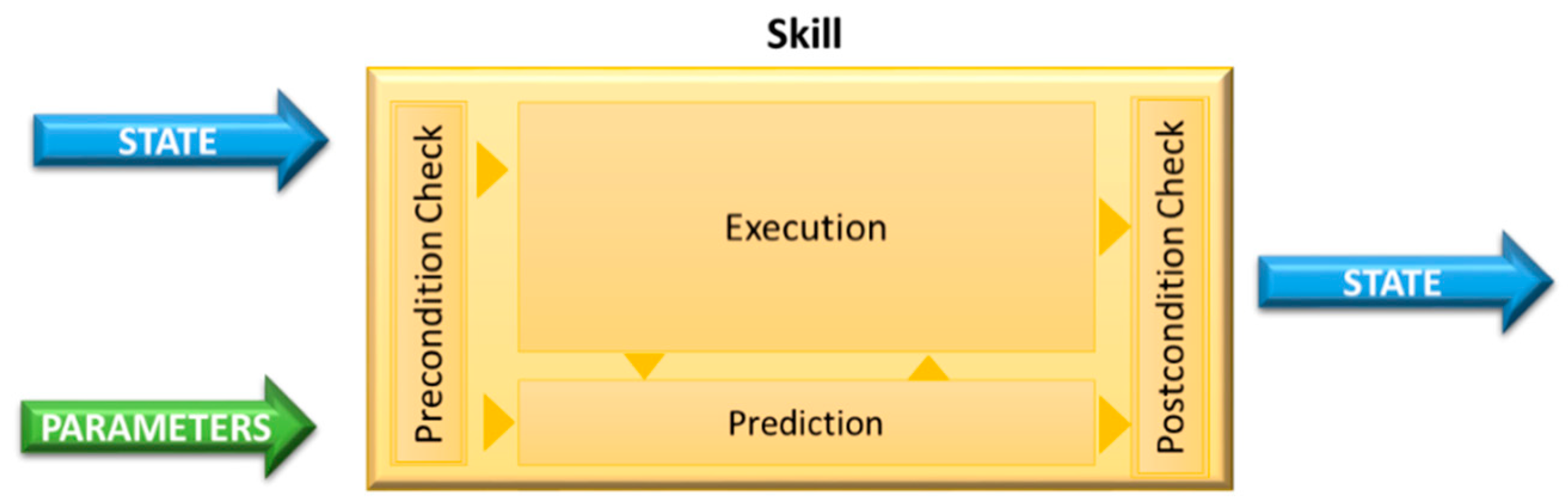
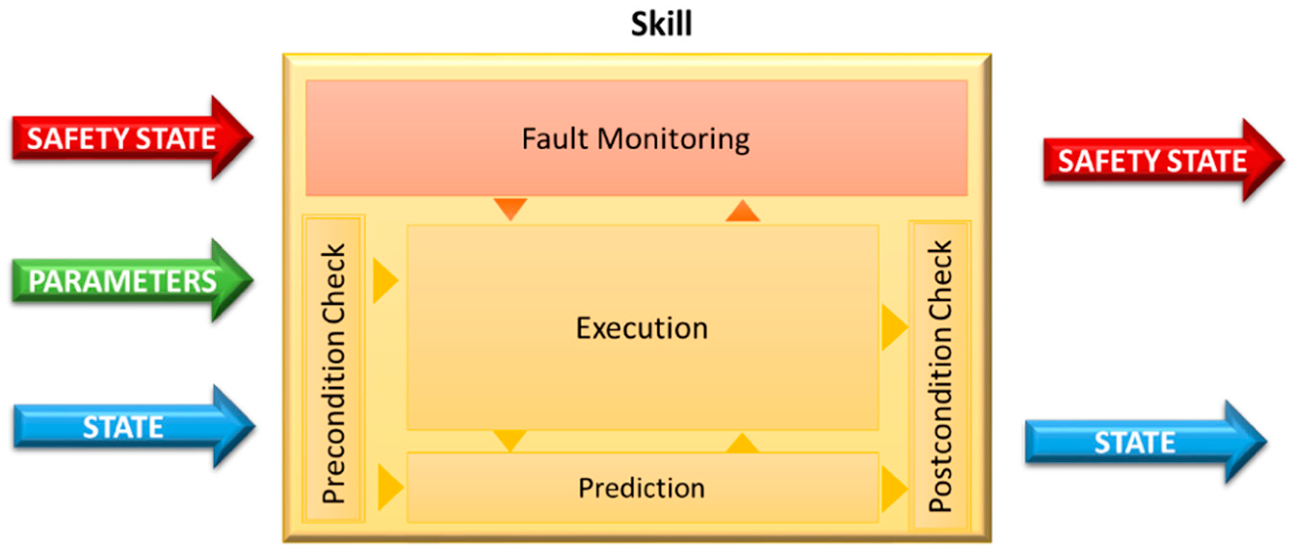
  • Skills as intuitive object-centered robot abilities that are self-sustained and can be used for task-level programming. Each skill has input parameters, executing instructions (combinations of primitives: sensing and acting operation sequences) and it is able to verify if the execution of the program was successful (or not).
  • Tasks as a set of skills planned to overcome a specific goal. Each task defines the input parameters of skills, accesses state variables of the robot/world, and changes these variables by controlling the execution of a predefined sequence of skills.
  • Missions as a sequence of tasks that are executed whenever necessary to achieve specific goals. Each mission captures high-level behavior that should be obtained after the execution of a set of predefined tasks. It defines input parameters and controls the workflow of tasks.
This model provides task-level programming based on lower level entities, called skills, which instantiate actions or sensing procedures. In this way, complex behaviors can be described in a more systematic and flexible manner, as well as, the effort to program new mission types is lower and the usage of primitives creates a hardware abstraction, which turns the task specification/program completely reusable; however, it is not clear how safety monitoring modules, fault supervision or even fault tolerance strategies can be incorporated.

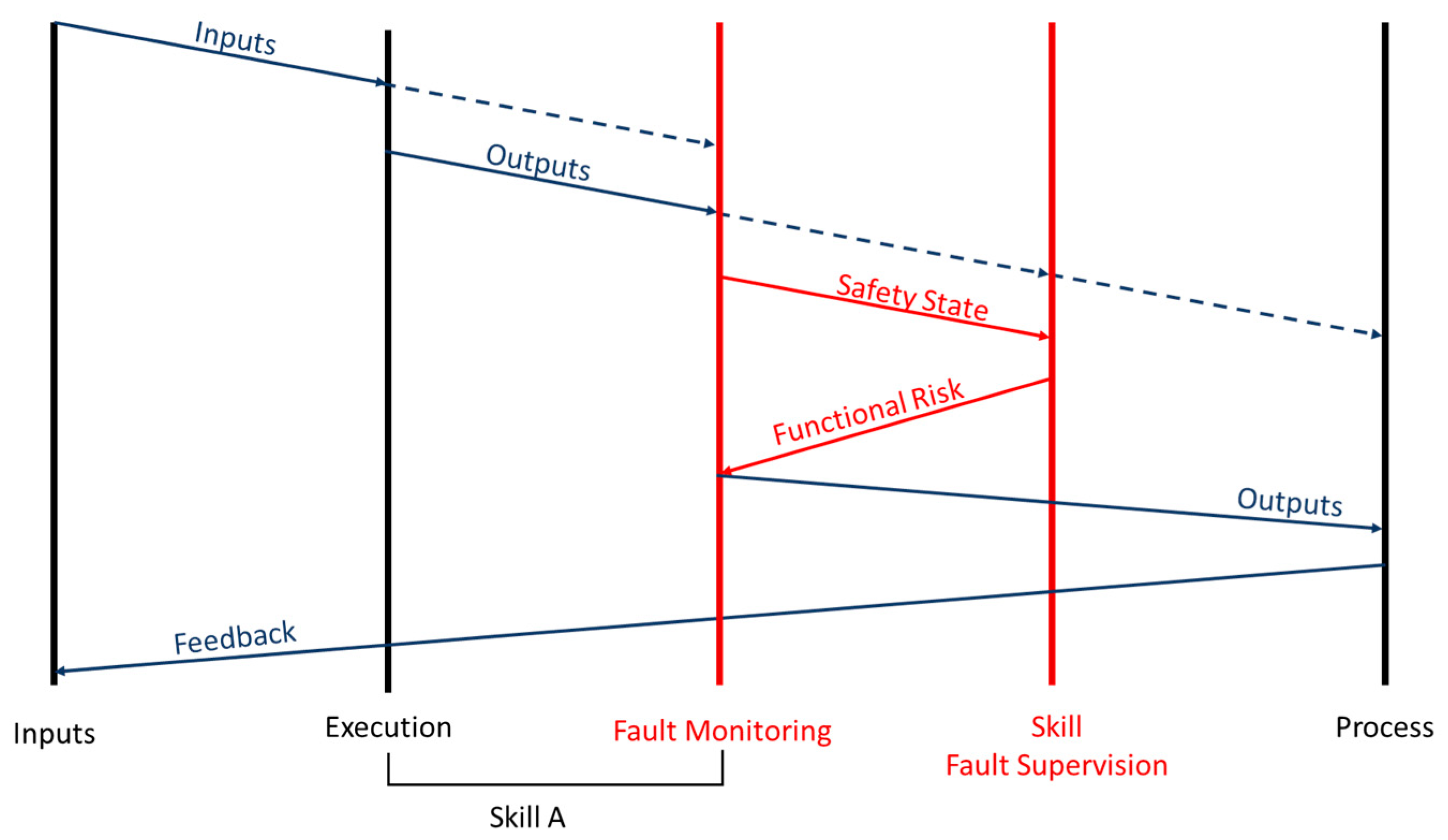
3.2. Safety Monitoring Model for Skills Architecture

This section presents a safety monitoring model that extends skill architecture. Generally, a robot architecture usually comprises of three types of components:
  • Sensors, which allow to receive input from the scenario
  • Actuators, which allow to interact with the scenario
  • Decisional layer (primitives, skills, tasks and missions), corresponding to the software module that defines or manages specific behaviors for the mobile robot.
Although the literature about fault tolerance, monitoring and supervision of hardware systems is rich with many strategies focused on functional redundancy, the same cannot be said for decisional layers for mobile robots, since it is quite rare to encounter a real application where the developers conducted risk analysis to their software modules.
The safety monitoring model proposed by this research is based on a functional decomposition of the decisional layer. This functional decomposition makes it possible to establish a hierarchical and distributed safety monitoring strategy, which extends the conceptual model of skill. A fault monitoring process is incorporated to each skill (see Figure 3), which aims to define a safety state of the skill by verifying deviations in the execution, and, considering perception uncertainties, potential hazardous situations (using causality assumptions), and probabilities of unwanted events related to software failures or human errors (events that are difficult to estimate). By incorporating fault-monitoring techniques for error detection (such as temporal control by a watchdog, model-based diagnosis monitoring), the concept of skill of Figure 2 can be extended by incorporating fault monitoring procedures (see Figure 3).
The fault monitoring of Figure 3 resorts to a different set of primitives, e.g., fault detection, fault location, skill reconfiguration or verification of a system’s results. Safety primitives are different in nature and thus usually provide a qualitative or quantitative characterization of the safety status of the hardware and software components. For this reason, the specificity of these primitives is inherent and dependent on the abilities defined by the skill (through the execution process), as well as the harm that potentially rises from their errors—a causality analysis should be determined by considering hazardous situations that could happen in the context of that skill. The fault monitoring process aims to reduce the risk expected for that specific skill and, therefore, provides safety features by running the monitoring process continuously in parallel with the remaining execution of the operational primitives. This fault monitoring estimates the safety state of the skill, which is defined by the availability and quality (which defines the dependability) and the potential failure severity of the service delivered by a component module (skill).
The safety state can be formulated using five levels that characterize a component module with different system integrities:
  • High (0-level): When no failures were detected and the service can be delivered
  • Medium (1-level): When failures were detected. The service can be delivered using the same function mode while adapting sub-objective parameters
  • Weak (2-level): When failures were detected. The service can be delivered using an alternative (potentially degraded) sub-objective while remaining at the current autonomy level
  • Serious (3-level): When failures were detected. The service cannot be delivered but other component modules can continue the mission with the current autonomy level (there is a reduced risk to hazardous situations)
  • Fatal (4-level): When failures were detected. The service cannot be delivered and the mission must stop since there is a high risk to hazardous situations.
The safety state of a skill can be determined, defined by a function (1) of the fault processes affecting the skill:
Safety   State = max   i Υ   ( i )   × [ χ ( i )   + ψ ( i ) ] ,      i A  
where A is the set of primitives being used by the skill, Υ ( i ) , χ ( i ) and ψ ( i ) specifies, respectively, the severity of harm, the influence on the availability and quality of the service provided by the skill, which is caused by a failure on the primitive “i”.
The quality assessment ψ ( i ) is defined by the persistence and the frequency of occurrence of a failure, see Equation (2):
ψ ( i ) = Persistence ( i ) × Occurence ( i )
The persistence metric measures the temporal nature of a failure: permanent (when the service quality is definitely affected), transient (when a failure is no-recurrent for a finite length of time) and intermittent (when a service oscillates between faulty and fault-free operation). While a permanent failure is more likely to be identified correctly, a transient or intermittent failure has a higher chance of being a false positive, a glitch that occurs because the environmental input led the system to a false conclusion, for example. This difference between permanent and intermittent was already established by the IEC 60050. Permanent fault is one that will not disappear unless there is intervention. Intermittent fault is a transient fault, meaning it does not require intervention to disappear; it continues to occur [35]. In this way, the persistence metric is defined by:
  • Persistence(i) = 1, then the failure “i” is Intermittent (or transient)
  • Persistence(i) = 2, then the failure “i” is Permanent
The occurrence metric defines the confidence that a skill will provide the service (at a random time) within the expected functional limits. The cost function of the frequency of occurrence can be defined by qualitative four levels:
  • Very low (=1). There will not be service interruptions
  • Low (=2). Service interruptions will happen at a low-frequency or high-confidence in delivering the expected result
  • High (=3). Service interruptions will happen at a medium-frequency basis or low-confidence in delivering the expected result
  • Relatively high (=4). Service interruptions will happen at a high-frequency basis.
The occurrence metric might be hard to calculate without a certain level of abstraction to the frequency of occurrence related to an unexpected event or a primitive that fails to deliver a pre-defined service. The frequency of occurrence can be estimated by preliminary tests (e.g., using a simulator or empirical experiences) to obtain the level of confidence about the integrity level of executing a set of primitives that form the operative skill.
The availability assessment χ ( i ) does not measure the frequency of occurrence of failures but instead, it pertains to how much the fault affects the ability of the system to perform a certain service. The availability metric measures the readiness for the correct service in the skill and can be defined by:
  • Redundant (=0), when the service remains available without loss of quality
  • Eminent (=1), when the service remains available with loss of quality
  • Singular (=2), when the fault removes the system’s ability (the service can no longer be delivered)
The availability assessment can be understood by a simple example. On a four-wheel Ackerman robot, let us consider the existence of four motors, one on each wheel is controlled by a primitive (PID-controller). If one primitive has a fault, it does not stop the ability of the robot to move; it only reduces the number of viable options. If another primitive fails later on, that condition will put the availability of the skill responsible for moving the robot in “Eminent” state, which means that no other fail is tolerable. However, if a fault occurred on the power source that feeds all the four motors, that fault will remove the ability of the robot to move.
Finally, the severity of harm Υ ( i ) is defined in two components namely, severity and extent of the functional failure. It is related to the severity of damage to the health of people, to the integrity of the robot, or to the environment (including human built structures) and, is defined by Equation (3):
Υ ( i ) = Severity ( i ) × Extent ( i )
The IEC 61508 defines risk as the “combination of the probability of occurrence of harm and the severity of that harm”; however, harm is considered to only pertain to people [8]. This research extends the definition of harm to include people, environment, and the robot itself. Thus, the extent of a functional failure is related to the fault propagation to other decisional modules. It tries to determine the danger of the fault: Is it a self-contained fault or could it spread to other components? The propagation of the failure depends on how contagious the fault is, for instance, a failure in the skill of “localization” will jeopardize with relative ease other navigation modules. It can be defined by:
  • Isolated disturbances (=1). Faults affect only the current component
  • External disturbances (=2). Faults propagate to other components and have a global impact.
The functional severity depends on the specificities of the robot, the mission and the environment. It specifies the acceptable consequences of the failures:
  • Absence of failures (=0), when the normal functioning of the decisional model does not cause harmful consequences
  • Minor failures (=2), when the harmful consequences lead to similar costs to the benefits provided by correct service delivery
  • Catastrophic failures (= 6), when the harmful consequences lead to costs with orders of magnitude higher than the benefit provided by correct service delivery.
These severity levels help to design and implement recovery strategies for skills and defines the level of harm that could be expected for a particular failure, i.e., the physical injury or damage to the health of people and damage to property or the environment either by a direct or indirect consequence of the mobile robot.
The severity of harm is an important consideration and, in this analysis, is tied to the level of extent and the functional severity of a system (skill) failure. The estimation of the severity of the harm is essential for a fault supervision and tolerance efficiency, since it can be used to guide the recovery or reconfiguration of decisional modules. It can also be argued that the severity of each parameter over the others is hard, if not impossible, to generalize. The functional nature of the fault might seem more important because of the potential to remove an ability from the mobile robot, but the propagation might cause multiple sub-systems to present problems, while the persistence might be the difference between a real fault and a false positive. Analysis of the importance of each of these parameters might even result in an infinity of situations in which their importance highly varies. This formula, on the other hand, allows a standard to emerge. If deemed necessary, it allows an easy process of adaptation to different contexts by adding coefficients, to be decided according to each case, to each parameter.
Equation (1), although it makes it hard to discriminate between different integrity levels, offers a simple way to evaluate the potential of the fault to endanger the mission (causing a hazardous situation). While Table 1 helps to visualize the combinations possible with the quality and availability assessments, it is in Table 2 that the full formula is show, and therefore, considering it the safety state can be defined by assigning thresholds for each level namely, “High” up to 5, “Medium” is between 6 and 20, “Weak” is between 21 to 42, “Serious” is between 43 to 60 and “Fatal” is between 61 to 120. This classification can be adapted as more details are known. In cases in which the mission does not have the potential to endanger people and it is vital that it is completed, for example, “Serious” and “Fatal” might be adapted and the entire classification can be shifted. However, it should always be noted that the first consideration must be risk. The safety of people must always be placed above the mission unless an extreme scenario is presented. To which skills to apply this model is also an important consideration. The standard form is defined for operational skills that are essential for the mission. For skills that are not crucial, this model can help to assess if there is any danger of faults spreading.
Fault monitoring must resort to a set of safety primitives and user parametrizations to characterize the level of persistence, occurrence, availability, extent, functional severity, required to estipulate the safety sate from Equation (1). These primitives must follow strategies for fault-detection and be implemented according to specificities of the robotic application, operational environment, and potential hazardous situations. They could be implemented by a set of safety rules done with a generic method: limit checking, trend checking, signal-model based, process-model based and multivariate data analysis [36].

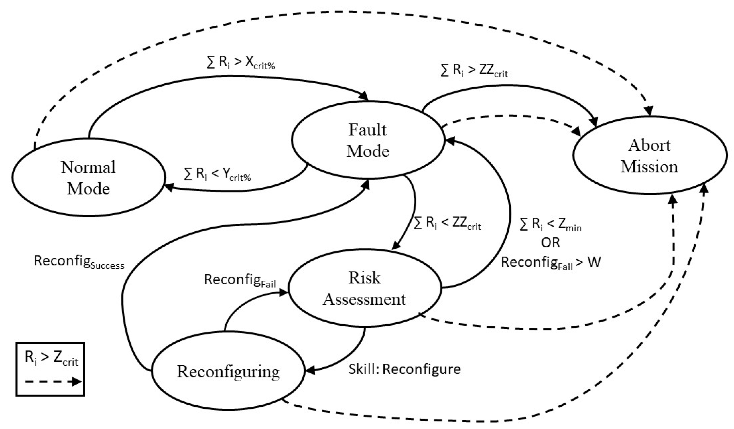
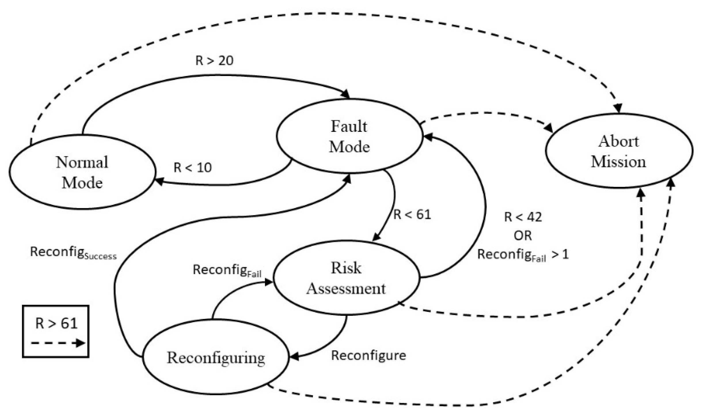
3.3. Decision-Making Model

Highly-complex software is more likely to have faults [5]. If there is a problem in the design of tasks and skills, or control, it is worse when concerning a sub-system, or module, whose objective is to handle autonomous decision-making, i.e., the ability of the system to decide, without human intervention, when in the presence of detected abnormal working condition (such as detected and diagnosed faults), it should cancel the mission, proceed as normal, or proceed with different parameters. Therefore, it should be designed with as much complexity as needed and as much simplicity as possible. To that end, the terms must first be better defined. Thus, the decisional architecture of the mobile robot can be represented by Figure 4:
This new hierarchical representation of the conceptual model adds a safety skill, “Fault Supervision” to each task. This special skill assesses the overall safety level of the entire task by considering the safety state obtained from other operational skills. This means that the “Fault Supervision” provides a general view of several risk analyses made by each skill so it is possible to conduct a functional system analysis. The system is forced to a safe state (recovery), should hazardous behavior be detected (error detection) by an external and independent layer.
In the decision to either continue or abort the mission, the safety state should be the main concern. How to proceed in case of the mission being cancelled should be evaluated to minimize the severity of harm for each application.
This is not a matter that can always be judged in a simple binary solution. The only situation in which the decision to procced or abort the mission is straight forward is when a skill reaches the Fatal level, as in that moment it is immediately understood that the risk of a hazardous situation is too high. On the opposite side of the spectrum, when all skills’ safety state is High, it is the obvious decision that the mission should procced, as there is no foreseeable risk of a hazardous event. At all other levels, the situation will be harder to assess. What combination of Medium, Weak and Serious safety states warrants caution? When does it become impossible for the system to deliver what the mission requires? As with so many things in life, many variables might need to be considered. How big is the vessel? What is the mission? Is it worth the potential of elevating the risk? Can some skills recover, thus improving their safety state?
Figure 5 illustrates the decision-making process through a state machine. It depends on various parameters:
  • Ri—Safety state of skill i
  • ∑ Ri—Cumulative safety states of every skill
  • Zcrit—Fatal level threshold for a single skill Ri
  • ZZcrit—Mission abort threshold for all skills ∑ Ri
  • Zmin—Threshold for all skills. If ∑ Ri is lower, the system reevaluates if the Fault Mode is required
  • Xcrit%—Threshold for all skills. If ∑ Ri is higher the system enters Fault Mode
  • Ycrit%—Threshold for all skills. If ∑ Ri is lower the system returns to Normal Mode
  • ReconfigSuccess—Flag that signals that the system/skill reconfiguration was successful
  • ReconfigFail—Flag that signals that the system/skill reconfiguration was unsuccessful
  • W—Control of the number of failed reconfigurations. Depends on which skills the Fault Supervision attempts to reconfigure.
As can be seen, should any skill, at any time, reach the Fatal level, the mission must be immediately terminated. In Normal Mode, the cumulative safety states present no or negligible risk and so no changes are needed. Fault Mode is applied when the risk is high enough that it requires evaluation. Should the cumulative safety states create an intolerable risk, the mission is canceled. If, however, the risk is still not high enough to cause an immediate abandonment of the mission, then the Assessment state must be called. In this, the Fault Supervision must consider all skills safety states to prioritize the calling of the reconfigure skill. The Reconfiguring state attempts to reconfigure each skill, according to the parameters defined in the previous state. It returns the functional risk so that the reconfiguring of each skill can be made in a more targeted way or, in extreme situation, that other preventive measures might be taken. These measures, should there be a need for them, are to be decided in the Fault Mode state.
The actions to be taken when the Abort Mission or Fault Mode states are activated will also vary with the mission type and the specific characteristics of the mobile robot, as well as with the highest risk faults detected. They cannot be universally defined because, without prior knowledge of all these variables, it is difficult to predict which decisions will cause more harm.
As can be seen in Figure 6, each skill requires inputs and, during its execution, generates outputs. Both inputs and outputs of skills are used in conjunction with the functional risk returned by the Reconfigure state of the “Fault Supervision” skill on fault monitoring. This is an essential characteristic as it allows to reevaluate the outputs before they reach the process.
Fault supervision takes into consideration the safety state of each operational skill in the same task, which defines the nature of the failure: the severity associated with the detected fault, the available resources, the robot´s current state and the autonomy level. The process for decision-making that describes the fault supervision must comprise of the following major primitives:
  • Reconfiguration (general safety state = medium)
  • Adaptation (general safety state = weak)
  • Autonomy adjustment (general safety state = serious)
  • Safety Waiting (general safety state = serious)
  • Definitive Stop (general safety state = fatal).
The final step of the decision-making, the decision itself, can also be standardized, but as previously stated, must allow customization to different situations, if needed. Systems vary, missions vary, even the moment in which the decision inside the mission is taken, might vary. These considerations are important so that even aborting a mission does not turn a high-risk situation into the hazardous event it tried to prevent.

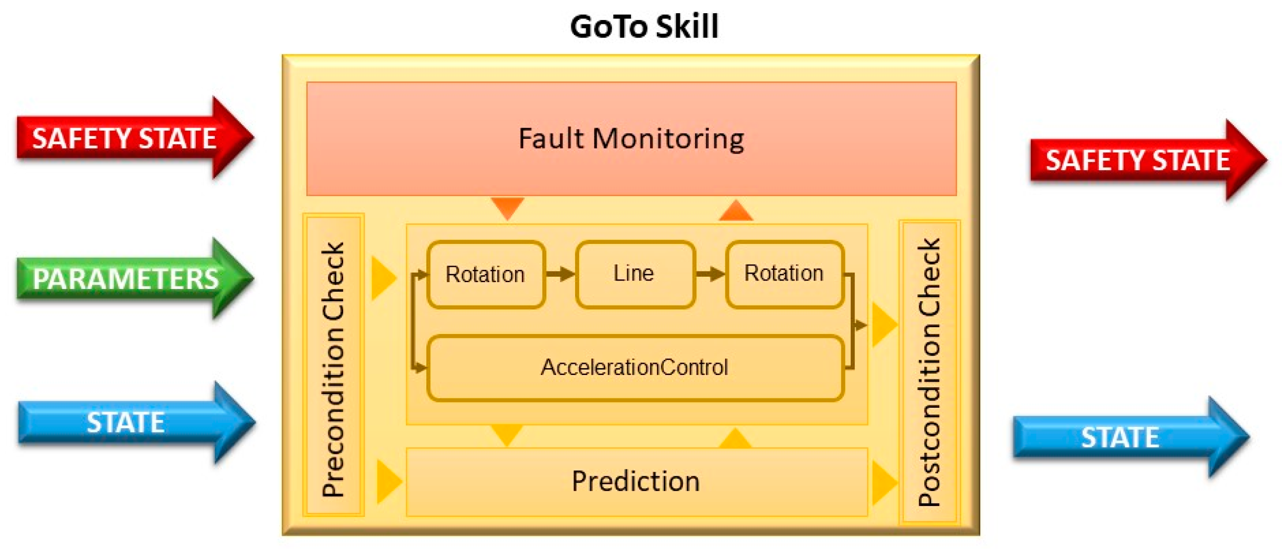
4. Practical Application

To exemplify how to apply this model, it will be considered that it is being used on an Autonomous Surface Vehicles (ASV), specifically a Zarco, illustrated in Figure 7, with a payload that gives it the ability to inspect bridges. It will be assumed that the system is fully capable of fault detection and diagnosis. The system is a catamaran developed by INESC TEC (Instituto de Engenharia de Sistemas e Computadores, Tecnologia e Ciência).
The Zarco is equipped with motion actuators, i.e., actuators that allow it to move, in the form of two electrical thrusters in a differential configuration. Next, an energy module composed of lead-acid batteries is the power source. Moving to sensors, Zarco only has value sensors, i.e., sensors that return a value or a set of values and which concern variables like positioning, acceleration or velocity. These include a pair of GPS receivers (L1 + L2 RTK), an Inertial Measurement Unit (IMU) and a magnetic compass. The navigation and communication, in terms of hardware, are based on an onboard computer and a Wi-Fi antenna and, in terms of software, into the functions that allow for autonomous mission completion and communication with the Ground Control Station (GCS) [37].
With the hardware and software that this system possesses, there are primitives that can be drawn. To exemplify the application of the proposed decision-making model, only a single movement-based skill will be considered.
One can easily define Rotation and Line as, respectively, a primitive that manages the angular movement and a primitive that manages the linear movement. Both are dependent on the motion actuators and the odometry (obtained by GPS and IMU), but the functions that control them are expressed by different mathematical equations. Furthermore, let us consider that there is a third primitive, called AccelerationControl, to evaluate the velocity of the ASV (avoiding dangerous accelerations/de-accelerations that may cause overcurrent) and therefore is dependent on all value sensors (GPS, IMU and magnetic compass). With these three primitives, it is possible to build a GoTo skill. This skill will be composed by a sequence Rotation-Line-Rotation, with Acceleration running in parallel.
As Figure 8 implies, the skill (and its primitives) requires a set of parameters:
  • Final Position—given by (x, y, θ), which translates into coordinates x and y, in meters, and by orientation θ, in degrees
  • Tolerable Position Error—given by (e, ε), which are small values for the tolerance of coordinate and orientation, respectively, error values that are within an acceptable margin
  • Nominal Velocity—named vn, expressed in meters per second, establishes the maximum trajectory speed
  • Elapsed Time—(Ρ1, Ρ2) seconds. Used to determine Persistence (used to calculate quality assessment ψ(i)). Will be further explained bellow.
The first three parameter sets are straightforward. They establish basic information that the system must know in order to perform its movement tasks. Although the error information and the nominal velocity could be constant, there is no harm in passing them as parameters to control the precision of the task. The Elapsed Time, however, only makes sense when used in the context of measuring the persistence of faults.
To assess the Persistence of the fault, there is the need to control how long a task is taking. Specifically, it requires to consider the following:
  • If task time exceeds a certain measure (/timeout), there is a permanent fault in the skill;
  • If the distance error does not reduce in less than Ρ1 seconds, there is an intermittent fault in the primitive Line;
  • If the orientation error does not reduce in less than Ρ1 seconds, there is an intermittent fault in the primitive Rotation;
  • If the acceleration is greater than the maximum allowed for more than Ρ2 seconds, there is an intermittent fault in the primitive AccelerationControl.
These measures of time will enable fault monitoring to extrapolate if a fault is intermittent or permanent, therefore solving one of the Safety State variables. A fault causing the /timeout to be exceeded is automatically a permanent fault (Persistence(i) = 2), while a fault causing elapsed times bigger than Ρ1 or Ρ2 is automatically an intermittent fault (Persistence(i) = 1).
To evaluate the remaining variables, and since they are mostly dependent on the affected primitive, we need to consider how they interact with the rest of the system or the implementation of the primitives themselves. The Occurrence, for example, only depends on how much confidence we have that something will do its job when it is required. Therefore, to calculate the Safety State of this GoTo skill, we must list some assumptions:
  • Because there is not sufficient hardware redundancy in the actuators, if they are the source of the fault, the Availability assessment χ(i) is Singular (=2)
  • Line has been deemed such a perfect algorithm to save space, only one implementation exists, although it never fails, Occurrence(Line) = 1
  • Rotation has been found to fail to perform in very rare occasions, but there are two different algorithms that can be called at any time, Occurrence(Rotation) = 2
  • AccelerationControl is a new feature, i.e., there is a low degree of confidence, and therefore has a medium-frequency of interruption, but to counter it are multiple algorithms that perform this task being compared against each other, Occurrence(AccelerationControl) = 3
  • Considering the above descriptions of the primitives’ implementations, if a fault is caused on the software side, the Availability assessment χ(i) of the primitives is different: Availability assessment χ(Line) = 2, Availability assessment χ(Rotation) = 1, Availability assessment χ(3) = 0
  • Field tests and expert assessment determined that a fault in the Rotation has a real, but small chance of causing harmful consequences, Severity(Rotation) = 2, but Line and Acceleration Control would have a high risk of catastrophic consequences, Severity(Line) = Severity (AccelerationControl) = 6
  • Because it is the only skill installed so far, but also because any mission could be adversely affected by a fault causing a position or orientation error beyond the tolerable margins, any fault to these primitives is considered to propagate, Extent(i) = 2.
These conditions solve all the variables. We now know exactly the value of each component of the Safety State in most, conditions. Persistence is to be decided dynamically according to time measures, Availability is also dynamic dependent on the redundancy left, Occurrence and Severity are hard coded, as well as the Extent due to the nature of this skill. A table like Table 3 can be built to aid in quickly calculating any Safety State for any situation, considering the current example:
We are now aware of the possible values for the Safety State of the GoTo skill, but we still need to consider the Fault Supervision. In this case, due to the small dimension of the system, including the single skill, the supervision is limited to a small decision-making process, as there are no cumulative values to consider. This means that Ri = ∑ Ri and that Zcrit = ZZcrit, since it would not make sense for GoTo’s Safety State to cause the mission to abort with two different values:
  • R—Safety state of GoTo skill
  • Zcrit—Fatal level threshold. Considering the basic level definition previously presented, 61 is the Fatal level
  • Zmin—Since, although there is only one skill, we still want the system to operate with some degree of confidence in its safety, unless reconfiguration is successful, reevaluation of the Fault Mode requires the Safety level to be at least Weak (w < 42)
  • Xcrit%—The system enters Fault Mode if the Safety level is Weak (w > 20)
  • Ycrit%—The system returns to Normal Mode if the Safety level is well within Medium level margins (w < 11)
  • W—Although some reconfiguration might be possible, hardware redundancy is so low that it is considered that it is only possible for the system to reconfigure itself successfully using Software changes, so this value is 1.
Considering, for example, an intermittent fault in the thrusters; all primitives will have Persistence(i) = 1 and Availability (i) = 2. That would mean that the Safety State of Line, Rotation and AccelerationControl would be, respectively, 24, 8 and 60. As a skill’s Safety State mirrors that of its worse primitive, GoTo would be 60. Thus, the decision-making would not deem it sufficient reason to abort the mission, but would enter Fault Mode and then proceed to Risk Assessment. As the level is Serious, it is above Zmin (Serious starts at Safety State = 43 and Z min is 42). The system does not have enough redundancy to reconfigure Hardware, so it may only try to reconfigure Software. In this case, it could try to change the Nominal Velocity parameter, or even the internal parameters of the AccelerationControl primitive. Let us assume it tried to change the Nominal Velocity, cutting it down by half. This does not change, in this case, the Safety State of the GoTo skill. However, it is a protection measure that allows the system to continue operating in the Fault Mode. But should the /timeout for the mission be reached, then the Safety State would change. Since AccelerationControl was already at the upper Serious level limit, we can easily start by calculating that and we will reach a Safety State of 96. This means its level is now Fatal. Since the skill assumes the Safety State of the primitive with the highest value, we now know that every possible value for GoTo skill places it at Fatal level, and therefore the mission is immediately aborted (such as would be the need in this case considering it is highly possible that the system cannot move at all). This state machine is illustrated in Figure 9.
This is a mere example of application, with some assumptions that are, admittedly, farfetched for simplicity of explanation. It is, nonetheless, capable of being expanded to real systems, where the assumptions are usually more factual. This example also exposes the need for a process that helps standardize the values of the parameters used in Safety State calculation, which should be based on a probability distribution function, as exemplified in [38] as soon as it would be possible to collect enough expert opinions to create such a model.

5. Conclusions

The creation of a universal decision scheme is not an easy task. In the field of robotics, especially considering the diversity of mobile robots that can already be seen, there are many variables that cannot be easily quantified. The number of components, the variety of skills, the amount of redundancy or the degree to which the system should be autonomous or “phone home” on limit scenarios are just some of the possible variables that one must grapple with in defining every single detail of a decision-making. The model proposed attempts to deal with the variables by creating a basis that is simple and effective enough that it can be applied as presented on systems, while allowing for easy adaptation according to the needs that are identified from the start of the project until the beginning of the decision-making module design.
The literature concerning fault detection, diagnosis and tolerance seems to identify a trend for optimal solutions to be limited to the system design timeframe. The decision-making module here presented cannot completely escape that paradigm but attempts to move the limit to the timeframe of its own development. This is done because a truly correct decision cannot be taken without all physical and non-physical aspects of the system being known.
This approach also tries to contain the propagation of errors to sequential skills or other decisional layers. As seen in Figure 4, the robot architecture proposed as the basis for the decision-making model isolates, as much as possible, the different software components of the system. Missions are broken down into tasks to be completed in a pre-determined order. Tasks are composed of different skills that are under permanent evaluation so that faults do not cause an abnormal behavior that leads to a hazardous event. Each skill is composed of simple primitives, rudimentary hardware-specific program blocks.
If the purpose is to give mobile robots the tools to become more autonomous, then their decision ability must be closer to the human ability to make decisions. One does not need to look past personal experience to understand that the risks people are willing to take depend on the sense of urgency, sometimes much more than on the knowledge of their own abilities or the danger of the situation. It is essential to know what components the system has, but also the purpose it has.
This paper aimed at conceptualizing a unified architecture for mobile robots. The thinking process started from the ground up, with small to medium size mobile robots in mind. Future work should look deeper into the decisions that should be taken by the “Fault Supervision” skill, particularly on big systems and less theoretical, or academic, scenarios. For example, a merchant ASV, on a system of such scale, it might be important to reduce the nominal velocity even when one skill reaches a weak safety state, or special signals might be required to use to warn the other ships in transit that the ASV might pose a certain level of risk. Even using two different models, each with its own safety state thresholds, and cross checking with a fuzzy model might be useful to better evaluate when actions must be taken.

Author Contributions

Conceptualization, A.L.; Methodology, A.P.; Validation, A.L. and A.P.; Formal Analysis, A.P.; Investigation, A.L.; Writing-Original Draft Preparation, A.L..; Writing-Review & Editing, A.P.; Supervision, A.M.; Project Administration, A.M.; Funding Acquisition, A.M.

Funding

This work is financed by the ERDF—European Regional Development Fund through the Operational Programme for Competitiveness and Internationalisation—COMPETE 2020 Programme within project «POCI-01-0145-FEDER-006961», and by National Funds through the FCT—Fundação para a Ciência e a Tecnologia (Portuguese Foundation for Science and Technology) as part of project UID/EEA/50014/2013.

Conflicts of Interest

The authors declare no conflict of interest.

References

  1. Zhang, T.; Zhang, W.; Gupta, M.M. An underactuated self-reconfigurable robot and the reconfiguration evolution. Mech. Mach. Theory 2018, 124, 248–258. [Google Scholar] [CrossRef]
  2. Nevejans, N. European Civil Law Rules in Robotics. In Policy Department C: Citizens’ Rights and Constitutional Affairs; European Parliament: Brussels, Belgium, 2017; p. 34. [Google Scholar]
  3. Kuestenmacher, A.; Plöger, P.G. Model-Based Fault Diagnosis Techniques for Mobile Robots. IFAC-PapersOnLine 2016, 49, 50–56. [Google Scholar] [CrossRef]
  4. Koren, I.; Krishna, C.M. Fault-Tolerant Systems; Elsevier Science: San Francisco, CA, USA, 2007; Available online: https://ebookcentral.proquest.com/lib/feup-ebooks/reader.action?docID=294597&query= (accessed on 30 January 2018).
  5. Guiochet, J.; Machin, M.; Waeselynck, H. Safety-critical advanced robots: A survey. Robot. Auton. Syst. 2017, 94, 43–52. [Google Scholar] [CrossRef]
  6. European Committee for Standardization. Agreement on Technical Co-Operation Between ISO and CEN (Vienna Agreement) [Internet]. Brussels: CENELEC. 2001, pp. 1–3. Available online: https://www.cencenelec.eu/intcoop/StandardizationOrg/Pages/default.aspx (accessed on 27 March 2018).
  7. European Committee for Electrotechnical Standardization. Cenelec guide 13—IEC-CENELEC Agreement on Common Planning of New Work and Parallel Voting [Internet]. Brussels: CENELEC. 2016. Available online: https://www.cencenelec.eu/intcoop/StandardizationOrg/Pages/default.aspx (accessed on 27 March 2018).
  8. MTL Instruments Group. An Introduction to Functional Safety and IEC 61508; MTL Instruments Group: Luton, UK, 2002; Available online: https://www.mtl-inst.com/images/uploads/datasheets/App_Notes/AN9025.pdf (accessed on 27 March 2018).
  9. Kolek, L.; Ibrahim, M.Y.; Gunawan, I.; Laribi, M.A.; Zegloul, S. Evaluation of control system reliability using combined dynamic fault trees and Markov models. In Proceedings of the 2015 IEEE 13th International Conference on Industrial Informatics (INDIN), Cambridge, UK, 22–24 July 2015; pp. 536–543. Available online: http://ieeexplore.ieee.org/document/7281791/ (accessed on 27 March 2018).
  10. Isermann, R.; Ballé, P. Trends in the application of model based fault detection and diagnosis of technical processes. Control Eng. Pract. 1997, 5, 709–719. [Google Scholar] [CrossRef]
  11. Yoshimura, I.; Sato, Y. Safety achieved by the safe failure fraction (SFF) in IEC 61508. IEEE Trans. Reliab. 2008, 57, 662–669. [Google Scholar] [CrossRef]
  12. Visinsky, M.L.; Cavallaro, J.R.; Walker, I.D. Robotic fault detection and fault tolerance: A survey. Reliab. Eng. Syst. Saf. 1994, 46, 139–158. [Google Scholar] [CrossRef] [Green Version]
  13. Isermann, R. Mechatronic systems-Innovative products with embedded control. Control Eng. Pract. 2008, 16, 14–29. [Google Scholar] [CrossRef]
  14. Sghairi, M.; De Bonneval, A.; Crouzet, Y.; Aubert, J.J.; Brot, P. Architecture optimization based on incremental approach for airplane digital distributed flight control system. In Proceedings of the Advances in Electrical and Electronics Engineering—IAENG Special Edition of the World Congress on Engineering and Computer Science 2008, San Francisco, CA, USA, 22–24 October 2008; pp. 13–20. [Google Scholar]
  15. Stoican, F.; Olaru, S.; Seron, M.M.; De Doná, A. A fault tolerant control scheme based on sensor-actuation channel switching and dwell time. Int. J. Robust. Nonlinear Control 2014, 24, 775–792. Available online: http://ieeexplore.ieee.org/xpls/abs_all.jsp?arnumber=5718146 (accessed on 27 March 2018). [CrossRef]
  16. Szurman, K.; Miculka, L.; Kotasek, Z. Towards a state synchronization methodology for recovery process after partial reconfiguration of fault tolerant systems. In Proceedings of the 2014 9th International Conference on Computer Engineering & Systems (ICCES), Cairo, Egypt, 22–23 December 2014; pp. 231–236. [Google Scholar]
  17. Liu, Z.; Zhang, Y.; Yu, X.; Yuan, C. Unmanned surface vehicles: An overview of developments and challenges. Annu. Rev. Control 2016, 41, 71–93. [Google Scholar] [CrossRef]
  18. Crestani, D.; Godary-Dejean, K.; Lapierre, L. Enhancing fault tolerance of autonomous mobile robots. Robot. Auton. Syst. 2015, 68, 140–155. [Google Scholar] [CrossRef] [Green Version]
  19. Gonzalez, O.; Shrikumar, H.; Stankovic, J.A.; Ramamritham, K. Adaptive fault tolerance and graceful degradation under dynamic hard real-time scheduling. In Proceedings of the Real-Time Systems Symposium, San Francisco, CA, USA, 2–5 December 1997. [Google Scholar]
  20. Strollo, E.; Trifiletti, A. A fault-tolerant real-time microcontroller with multiprocessor architecture. In Proceedings of the MIXDES 2016—23rd International Conference Mixed Design of Integrated Circuits and Systems, Lodz, Poland, 23–25 June 2016; pp. 431–436. [Google Scholar]
  21. Ma, H.J.; Yang, G.H. Simultaneous fault diagnosis for robot manipulators with actuator and sensor faults. Inf. Sci. 2016, 366, 12–30. [Google Scholar] [CrossRef]
  22. Ranjbaran, M.; Khorasani, K. Fault recovery of an under-actuated quadrotor aerial vehicle. In Proceedings of the 49th IEEE Conference on Decision and Control (CDC), Atlanta, GA, USA, 15–17 December 2010; pp. 4385–4392. [Google Scholar]
  23. Zhang, M.; Wu, J.; Wang, Y. Simultaneous faults detection and location of thrusters and sensors for autonomous underwater vehicle. In Proceedings of the 2011 Fourth International Conference on Intelligent Computation Technology and Automation, Shenzhen, China, 28–29 March 2011; Volume 1, pp. 504–507. [Google Scholar]
  24. Zajac, M. Online fault detection of a mobile robot with a parallelized particle filter. Neurocomputing 2014, 126, 151–165. [Google Scholar] [CrossRef]
  25. Saied, M.; Lussier, B.; Fantoni, I.; Francis, C.; Shraim, H.; Sanahuja, G. Fault diagnosis and fault-tolerant control strategy for rotor failure in an octorotor. In Proceedings of the 2015 IEEE International Conference on Robotics and Automation (ICRA), Seattle, WA, USA, 26–30 May 2015; pp. 5266–5271. [Google Scholar]
  26. Gross, J.N.; Gu, Y.; Rhudy, M.B.; Lassak, K. A Fault-Tolerant Multiple Sensor Fusion Approach Applied to UAV Attitude Estimation. Int. J. Aerosp. Eng. 2016, 2016. [Google Scholar] [CrossRef]
  27. Bader, K.; Lussier, B.; Schön, W. A fault tolerant architecture for data fusion: A real application of Kalman filters for mobile robot localization. Robot. Auton. Syst. 2017, 88, 11–23. [Google Scholar] [CrossRef]
  28. Shen, Z.; Ma, Y.; Song, Y. Robust Adaptive Fault-tolerant Control of Mobile Robots with Varying Center of Mass. IEEE Trans. Ind. Electron. 2017, 65, 2419–2428. Available online: http://ieeexplore.ieee.org/document/8012422/ (accessed on 27 March 2018). [CrossRef]
  29. Pedersen, M.R.; Nalpantidis, L.; Andersen, R.S.; Schou, C.; Bøgh, S.; Krüger, V.; Madsen, O. Robot skills for manufacturing: From concept to industrial deployment. Robot. Comput. Integr. Manuf. 2016, 37, 282–291. [Google Scholar] [CrossRef]
  30. Cai, M.Y.; Liu, C.J.; Wang, J.W.; Lin, Y.; Van Luttervelt, C.A.; Zhang, W.J. A new safety theory: Concept, methodology, and application. In Proceedings of the 2016 IEEE 11th Conference on Industrial Electronics and Applications (ICIEA), Hefei, China, 5–7 June 2016; pp. 1323–1327. [Google Scholar]
  31. Zhang, T.; Zhang, W.; Gupta, M. Resilient Robots: Concept, Review, and Future Directions. Robotics 2017, 6, 22. Available online: https://www.mdpi.com/2218-6581/6/4/22 (accessed on 27 March 2018). [CrossRef]
  32. Zhang, W.J.; Lin, Y.; Sinha, N. On the Function-Behavior-Structure Model for Design. In Proceedings of the Canadian Design Engineering Network Conference, Kaninaskis, AB, Canada, 18–20 July 2005. [Google Scholar]
  33. Zhang, W.J.; Wang, J.W. Design theory and methodology for enterprise systems. Enterp. Inf. Syst. 2016, 10, 245–248. [Google Scholar] [CrossRef] [Green Version]
  34. Schou, C.; Andersen, R.S.; Chrysostomou, D.; Bøgh, S.; Madsen, O. Skill-based instruction of collaborative robots in industrial settings. Robot. Comput. Integr. Manuf. 2018, 53, 72–80. [Google Scholar] [CrossRef]
  35. International Electrotechnical Commission (IEC). IEC 60050-192 International Electrotechnical Vocabulary—Part 192: Dependability; IEC: Geneva, Switzerland, 2015. [Google Scholar]
  36. Muenchhof, M.; Beck, M.; Isermann, R. Fault tolerant actuators and drives—Structures, fault detection principles and applications. In Proceedings of the 7th IFAC Symposium on Fault Detection, Supervision and Safety of Technical Processes, Barcelona, Spain, 30 June—3 July 2009; Volume 42, pp. 1294–2003. [Google Scholar] [CrossRef]
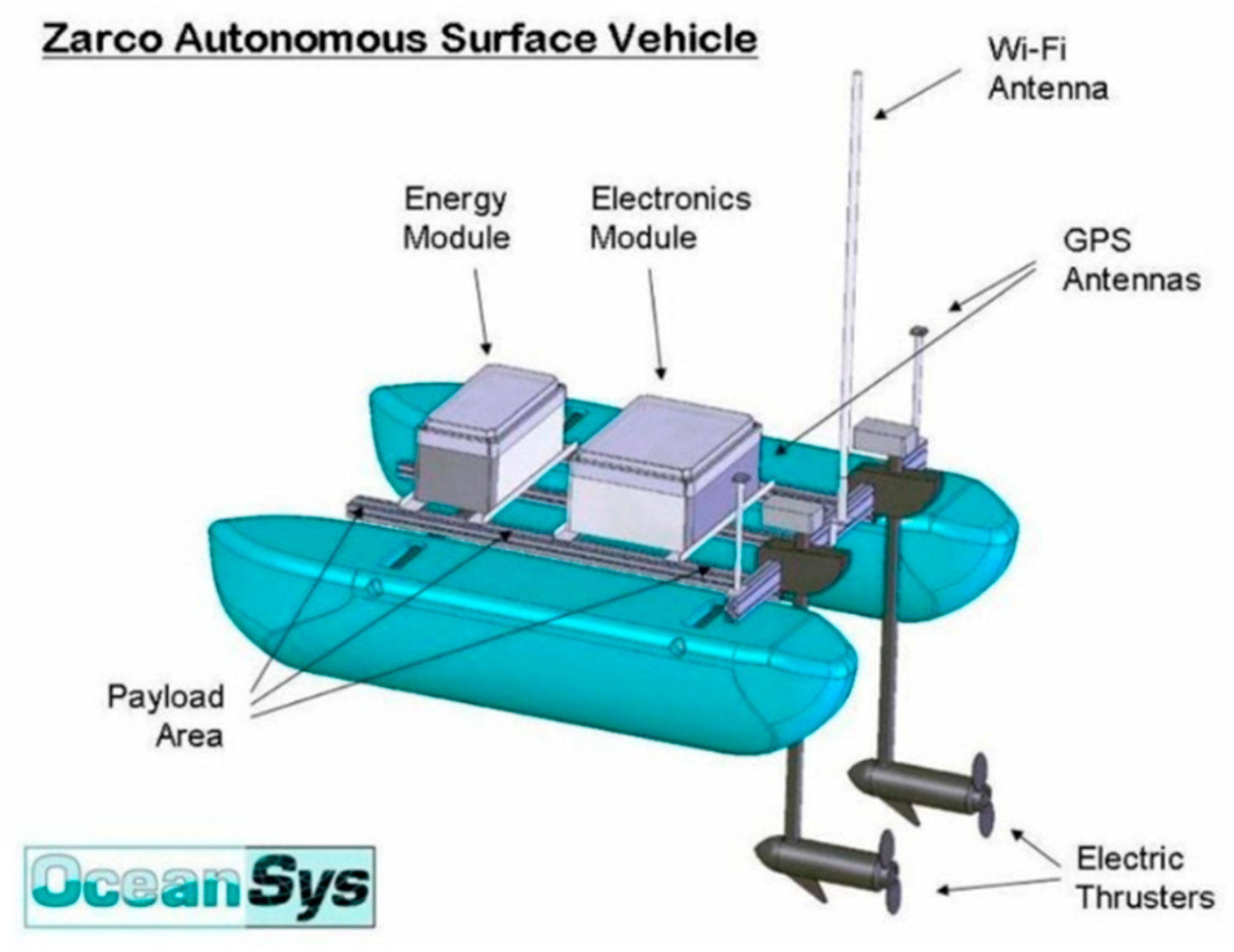
  37. Cruz, N.; Matos, A.; Cunha, S.; Silva, S. Zarco—An Autonomous Craft for Underwater Surveys. In Proceedings of the 7th Geomatic Week, Barcelona, Spain, 20–23 February 2007. [Google Scholar]
  38. Cai, M.; Lin, Y.; Han, B.; Liu, C.; Zhang, W. On a simple and efficient approach to probability distribution function aggregation. IEEE Trans. Syst. Man Cybern. Syst. 2017, 47, 2444–2453. [Google Scholar] [CrossRef]
Figure 1. Triple Modular Redundancy for a position system.
Robotics 07 00032 g001
Figure 2. Concept of skills without safety monitoring.
Robotics 07 00032 g002
Figure 3. Concept of skills with safety monitoring.
Robotics 07 00032 g003
Figure 4. Representation of the tasks and skills hierarchy.
Robotics 07 00032 g004
Figure 5. Decision-making state machine.
Robotics 07 00032 g005
Figure 6. Temporal representation of the system.
Robotics 07 00032 g006
Figure 7. Zarco, an ASV, in operation at the University of Porto since 2005.
Robotics 07 00032 g007
Figure 8. Illustration of the GoTo skill.
Robotics 07 00032 g008
Figure 9. Decision-making state machine with only GoTo skill.
Robotics 07 00032 g009
Table 1. Determination of the quality and availability assessments.
χ(i) ψ(i)OccurrencePersistence
RedundantEminentSingular
χ(i) + ψ(i)1231Very LowIntermittent
2342LowIntermittent
3453HighIntermittent
4564Relatively highIntermittent
2342Very LowPermanent
4564LowPermanent
5675HighPermanent
89108Relatively highPermanent
Table 2. Determination of the Safety State as a function of the severity of harm, quality and availability assessments.
χ(i) + ψ(i)Υ(i)ExtentF. Severity
12345678910
Safety State00000000000IsolatedAbsence
24681012141618202IsolatedMinor
61218243036424854606IsolatedCatastrophic
00000000000ExternalAbsence
4812162024283236404ExternalMinor
122436486072849610812012ExternalCatastrophic
Table 3. Possible Safety State values on applying known values.
Safety   State = m a x   i Υ   ( i )   × [ χ ( i )   + ψ ( i ) ]
(Severity × Extent) × [Availability + (Persistence × Occurrence)]
Safety State (w)
Line ( 6   × 2 )   × [ Availavility   + ( Persistence   ×   1 ) ] 12 w 48
Rotation ( 2   × 2 )   × [ Availavility   + ( Persistence   ×   2 ) ] 8 w 24
AccCtrl ( 6   × 2 )   × [ Availavility   + ( Persistence   ×   3 ) ] 36 w 96

