Abstract
In this work the velocity, acceleration, and jerk analyses of a two-degrees-of-freedom parallel wrist are approached by means of the theory of screws. For the sake of completeness, the finite kinematics of the manipulator is also investigated. As far as the authors are aware, the equation of jerk in screw form of the robot at hand is introduced by the first time in this contribution. In order to exemplify the method, a case study is included. The numerical example is verified with the aid of commercially available software.
1. Introduction
Usually a spherical mechanism is a limited-dof parallel manipulator that has the virtue that all its moving points describe paths forming concentric spherical surfaces. The most investigated parallel manipulator possessing such property is the named Agile Eye [1]. A two-degrees-of-freedom (2-dof) parallel wrist is a limited-dof spherical parallel manipulator capable to orient a line in the space allowing interesting applications in antennas, telescopes, biomechanics, telesurgery, haptic devices (joysticks), car gearshift, cameras and so far. Carricato and Parenti-Castelli [2] introduced a novel pointing fully decoupled 2-dof parallel wrist with linear actuators. Vertechy and Parenti-Castelli [3] investigated 2-dof spherical parallel manipulators equipped with linear actuators. A new fully decoupled 2-dof wrist named Hemisphere was proposed by Li et al. [4]. Ueda et al. [5] introduced a novel 2-dof parallel wrist with the purpose to work with heavy loads. Li et al. [6] proposed a redundantly actuated parallel wrist to realize two degrees of freedom. None of the contributions cited in this paragraph considered the jerk analysis.
The jerk is the time rate of the acceleration and has a direct connection with the forces and moments generated in multi body systems, e.g., it is known that there is a direct relationship between the jerk and human movements [7,8,9,10]. Gielen et al. [11] noted that the charactecteristic pattern of cerebellar ataxia, related with the jerk and submovements, is contained in the trajectory of the hand during repeated arm movements. In that concern, as it was concluded by Carricato and Parenti-Castelli [2] a 2-dof wrist is a viable option for the development of prosthesis design and humanoid robotics because the relative motion between two adjacent human segments may be regarded in most cases as a pure rotation. The jerk analysis is also useful to elucidate the singularities of mechanisms, e.g., Sparis and Mouroutsos [12] applied the jerk analysis in order to improve and control the position analysis of planar mechanisms, when the mechanism is near at a singular configuration. As noted by Dolgui and Pashkevich [13], by means of explicit verification of the velocity/acceleration constraints in wrist robots it is possible to obtain an optimization technique that allows to perform high-speed robotic laser cutting. Although in practical machining operations there are some problems concerned with instantaneous changes of feed rate due to limitations on the servo drive system [14], the generation of smooth trajectories based on confined contour error, acceleration/deceleration planning (jerk continuity) and machine dynamic response simultaneously can improve machining operations [15]. On the other hand, to the best knowledge of the authors, the first contribution approaching the jerk analysis of rigid body by means of the theory of screws is credited to Rico et al. [16].
In this work the finite kinematics of a 2-dof parallel wrist is reported in closed-form solution whereas the velocity, acceleration and jerk analyses are approached by means of the theory of screws. Simple input-output infinitesimal kinematic equations are obtained in the contribution by resorting to reciprocal-screw theory. The singularities of the spatial mechanism are also briefly explained. In order to enhance one of the possible applications of the robot at hand it is worth to mention that in an interesting contribution, Novàk [17] studied the motions of subjects turning a knob and concluded that on many trials, subjects turned the knob with a single, smooth, and regular motion as indicated by the angular position and velocity trajectories, but on others cases, subjects produced irregularities in the kinematics, which were considered as discrete corrective submovements, detecting appreciable inflections in the acceleration traces. It is reasonable to assume that the jerk would be the responsible of such irregularities owing the abrupt acceleration changes. In that concern, the parallel wrist considered in the contribution can be used to measure the jerk analysis of human hand. In fact, the knob may be operated manually by human and with the aid of encoders the instantaneous motions of the servo motors may be obtained. Finally, the jerk analysis would be computed by means of the theory of screws.
2. Preliminary Concepts
The mathematical tool selected to approach the infinitesimal kinematics of the parallel wrist is the theory of screws [16,18,19,20]. In order to provide a proper foundation of this work, this section is devoted to briefly explain some relevant results dealing with the velocity, acceleration and jerk analyses of kinematic chains by means of screw theory.
Consider an open kinematic chain composed of m rigid bodies serially connected by means of screw (helical) pairs. The direction of the screw pair, namely the Instantaneous Screw Axis (ISA), that connects bodies j and is given by the normalized vector while the pitch of the screw is notated as . The pitch and the direction of the screw are entities used to determine the so-called moment part as
where τ is a vector pointed from an arbitrary point embedded to the screw axis to the point O chosen as the reference pole. After, the screw pair, notated as , is a six-dimensional vector given by . For revolute joint we have yielding while in a prismatic joint the pitch goes to infinity yielding . Other kinematic pairs such as cylindrical, spherical or plane pairs may be modeled as a combination of screw pairs.
The velocity state, or twist about a screw, of a rigid body is defined as a six-dimensional vector given by , where ω and are the angular and linear velocities of the body in motion considering O as the reference pole. Meanwhile the reduced acceleration state of a rigid body is defined as , where α is the angular acceleration of the body and is the linear acceleration of point O. Furthermore, a representation of the reduced jerk state may be defined as , where ρ is the angular jerk of the body whereas is the linear jerk of point O. The velocity, acceleration and reduced jerk states satisfy the conditions of helicoidal vector fields [21].
Consider a serial chain formed with rigid bodies where adjacent links are connected by means of screws or helical pairs. The velocity state can be expressed in screw form as
where denotes the joint-velocity rate between adjacent bodies. On the other hand, the reduced acceleration state may be written as
where denotes the joint-acceleration rate between adjacent bodies. Furthermore, the Lie screw of acceleration is computed as follows
where the brackets denote the Lie product of the Lie algebra of the Euclidean group .
Finally, the reduced jerk state in screw form is given by
where denotes the joint-jerk rate between adjacent bodies. Furthermore, the Lie screw of jerk is given by
3. Description of the Parallel Wrist
The spherical parallel manipulator at its reference configuration is depicted in Figure 1.
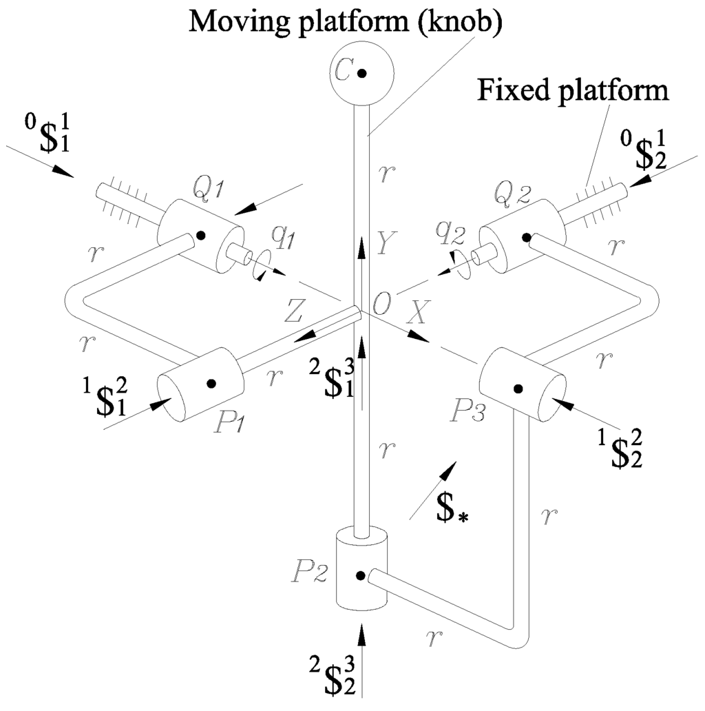
Figure 1.
The spherical wrist under study and its geometric scheme.
The spatial mechanism consists of a moving platform (knob) and a fixed platform (base) connected each other by means of two distinct kinematic chains or limbs, RR and RRR, where the actuators, which are conveniently mounted on the fixed platform, are indicated with underlines. All the revolute joints have concentric axes and therefore the linear kinematic properties of point O vanish. Furthermore, please note that one primary feature of the wrist at hand is that the axes associated to adjacent revolute joints are orthogonal. The mobility of the mechanism can be easily explained taking into account that due to the chosen architecture, the RRR-type limb can be considered as a 3-dof spherical serial manipulator. However, the connection of the knob through the RR-type limb is such that the knob cannot rotate along any axis normal to the plane formed by the primal parts of the screws and . Therefore the wrist at hand losses one of its three degrees of freedom. A robot manipulator like this may be used in the field of robotic exoskeletons, even though its limited degrees of freedom, e.g., for simulating motions of human wrist [22]. Furthermore, taking into account that there is a direct relationship between human movements and jerk, the inclusion of the jerk analysis in the contribution is absolutely justified.
4. Finite Kinematics
In this section the displacement analysis of the parallel wrist is presented. The forward position analysis of the parallel wrist is formulated as follows: given the generalized coordinates and , see Figure 1, compute the rotation matrix of the knob with respect to the base. To this end, consider as a reference frame attached to the base whose origin O is instantaneously coincident with the point of zero linear kinematic properties of the moving knob. For simplicity, significative points of the mechanism like , , , , and C are located on a sphere of radius r and center O. Then, immediately emerges that
Furthermore, in order to compute the coordinates of point the following closure equations should be taken into account
where the dot denotes the usual inner product of three-dimensional vectorial algebra and are the position vectors of points expressed in the reference frame . After a few computations one obtains
where . With regards to the point C of the knob
Finally, once the coordinates of point are calculated, the rotation matrix may be computed based on the unit vectors according to [23] as follows
On the other hand, the inverse position analysis of the parallel wrist consists of finding the generalized coordinates and given a prescribed trajectory of the point C of the knob with respect to the base, is a simple task and it is included here only for the sake of completeness. The inverse position analysis is immediately solved due to the decoupled motions of the knob. In fact, given , where evidently , the generalized coordinates and are obtained as
Furthermore, assuming that the orientation of the knob is defined by angles θ and β according to the fixed reference frame , see Figure 2, the generalized coordinates and are determined as
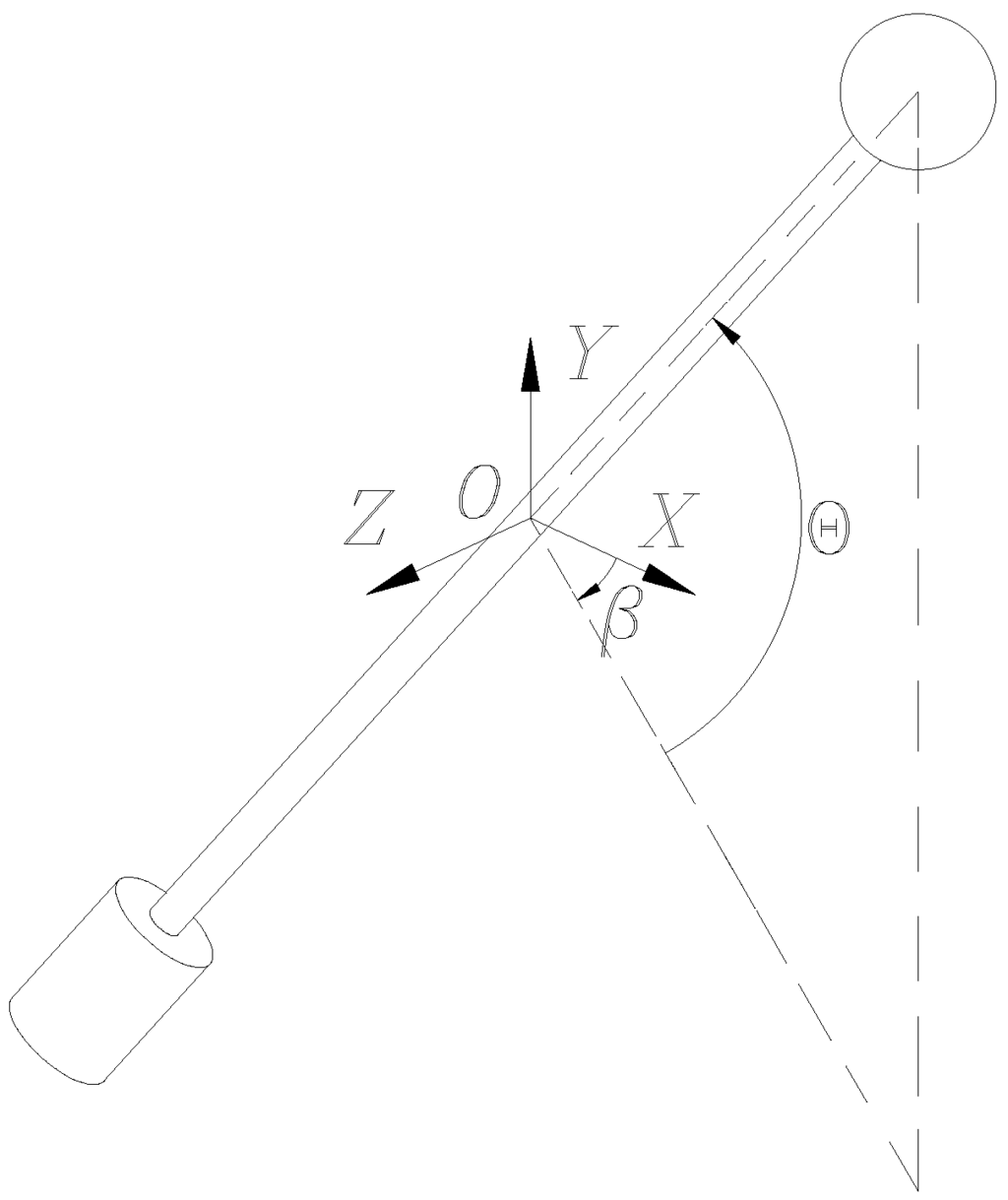
Figure 2.
Orientation angles of the knob.
5. Infinitesimal Kinematics
In this section the velocity, acceleration, and jerk analyses of the parallel wrist are approached by means of the theory of screws. The infinitesimal screws representing the kinematic pairs of the mechanism are depicted in Figure 1.
5.1. Velocity Analysis
The velocity state of the moving platform with respect to the fixed platform, vector , can be written in screw form through any of the two limbs of the manipulator as follows
where is an auxiliary screw associated to a fictitious revolute joint introduced with the purpose to satisfy an algebraic requirement, it is evident that .
The inverse velocity analysis (IVA) of the wrist consists of finding the joint-rate velocities of the manipulator given a prescribed velocity state . After reducing terms, the IVA is carried-out directly from Equation (14). On the other hand, the forward velocity analysis (FVA) of the mechanism consists of computing the velocity state given the generalized velocities and . In what follows, the FVA is simplified by applying the concept of reciprocal screws. To this end, consider that from Equation (14) it is possible to write
With reference to Figure 2, the line is directed from point to point , where the primal and dual parts, and , of the line are given by and . Clearly, after reducing terms, the application of the Klein form of the line to both sides of Equation (15), yields the passive joint velocity rate . The substitution of into the first equation of (14) allows to obtain the velocity state as follows
5.2. Acceleration Analysis
The reduced acceleration state of the moving platform with respect to the fixed platform, vector , can be written in screw form through any of the two limbs of the manipulator as follows
where .
The inverse acceleration analysis (IAA) of the parallel wrist consists of finding the joint-rate accelerations of the manipulator given a prescribed reduced acceleration state . After reducing terms, the IAA is carried-out directly from Equation (17). On the other hand, the forward acceleration analysis (FAA) of the mechanism consists of finding the active-joint-rate accelerations and given a prescribed reduced acceleration state . To this aim, from Expressions (17) it follows that
5.3. Jerk Analysis
The reduced jerk state of the moving platform with respect to the fixed platform, vector , can be written in screw form through any of the two limbs of the manipulator as follows
where
The inverse jerk analysis (IJA) of the mechanism consists of finding the joint-rate jerks of the manipulator given a prescribed reduced jerk state . After reducing terms, the IJA is carried-out directly from Equation (20). On the other hand, the forward jerk analysis (FJA) of the parallel wrist consists of finding the reduced jerk state for a given set of active- joint-rate jerks and . To this aim, from Expressions (20) it follows that
The application of the Klein form of the line to both sides of Equation (22) allows to compute the passive joint jerk rate . Substituting this result into the first Equation of (20), the reduced jerk state is obtained as
Expressions (16), (19) and (23) are simple, linear, compact and as far as the authors are aware were not derived in screw form in previous works for the robot under study. On the other hand, it is expected that the dual parts of the velocity, acceleration and jerk states of the parallel wrist vanish due to the concentric infinitesimal screws.
6. Singularity Analysis
A singularity occurs when the moving platform gains or loses degrees of freedom. Under such situation at least one of the kinematic analyses of the wrist is indefinite. The first type of singularity to be analyzed is related with the finite kinematics of the wrist, usually referred as structural singularities. To this aim, please note that according to Y, the forward position analysis is indefinite if . Of course it is an unrealistic possibility and must be disregarded immediately from the analysis, in other words, the parallel wrist is free of structural singularities concerned with the forward displacement analysis. On the other hand, an input-output position equation of the wrist may be written as follows
where P are the coordinates of a point of the knob expressed in the reference frame , p are the coordinates of the same point but expressed in a moving reference frame attached to the knob and is the rotation matrix given in Equation (11). It is straightforward to show that the inverse position analysis is indefinite when vanishes. Therefore, this singularity occurs when
After, the corresponding singular surface is given in Figure 3.
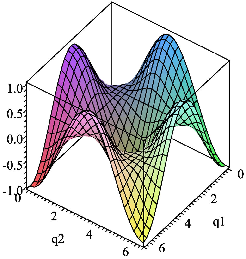
Figure 3.
Finite kinematics. Inverse singular surface in loci form.
The second type of singularity is related with the infinitesimal kinematics of the wrist. To this end, a linear combination of the screws in the same limb may be written as
In the inverse velocity analysis, a singularity is present when the screws in Expression (26) are linearly dependent. Due to the physical orthogonality imposed to adjacent revolute joints in the same limb, none of the screws in Equation (26) can be obtained as a linear combination of the remaining screws, therefore the wrist is free of this type of singularity. Finally, please note that according to Equation (16), the forward velocity analysis is indefinite when , in other words when the screws and are reciprocal, this singularity is present when both screws intersect and the equation governing such situation, considering that , results in
7. Results and Discussion
In this section a numerical example is provided in order to show the application of the method of kinematic analysis. To this end, the parameters of the wrist are given as follows: , and , where SI units are used through the exercise.
The first part of the case study is concerned with the inverse position analysis. To this aim, consider that the orientation angles θ and β are commanded to follow periodical functions given by
where the time t is chosen in the interval . After, the resulting instantaneous generalized coordinates meeting such conditions, given as simple plots, are provided in Figure 4.
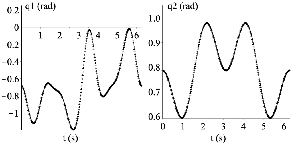
Figure 4.
Inverse position analysis. Temporal behavior of the instantaneous generalized coordinates.
The next part of the numerical example consists of computing the angular velocity and acceleration of the knob as measured from the base link taking into account that the generalized coordinates and of the robot must follow periodical functions given by
To this aim, the method reported in the contribution was translated into a Maple16©sheet. Afterwards, the resulting temporal behavior of the angular velocity and acceleration of the knob is given in Figure 5. Furthermore, in order to verify the numerical results obtained by employing the theory of screws, simulations were carried out by means of special software like ADAMS©. The corresponding plots are given in Figure 5.
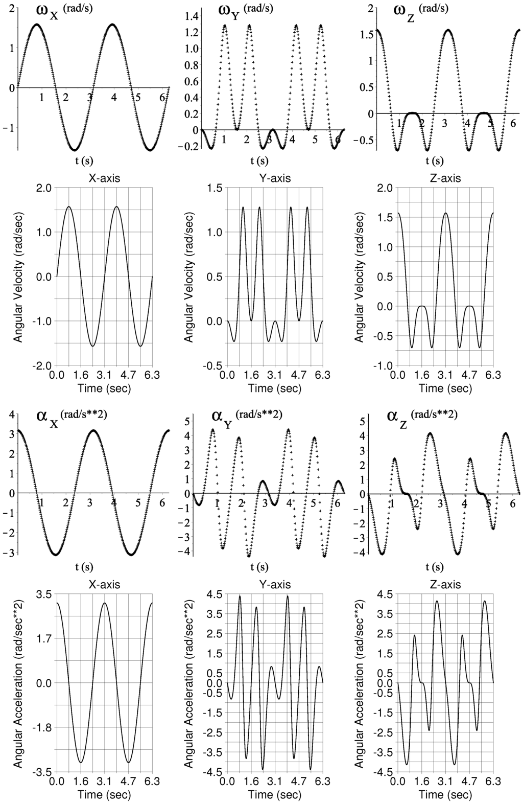
Figure 5.
Time history of the angular velocity and acceleration of the knob as measured from the base using screw theory, upper plots, and its validation using ADAMS©, lower plots.
It is worth to note that the numerical results obtained by employing the theory of screws are in excellent agreement with those generated by using a different strategy such is the use of commercially available software. On the other hand, the temporal behavior of the angular jerk of the knob with respect to the base computed via screw theory is given in Figure 6. It is worth to write that the jerk analysis of mechanical systems is not available in ADAMS©. Thus, as it was suggested by one of the reviewers, the jerk analysis was verified by numerically differentiating the result of the acceleration analysis. The corresponding plots are shown in Figure 6.
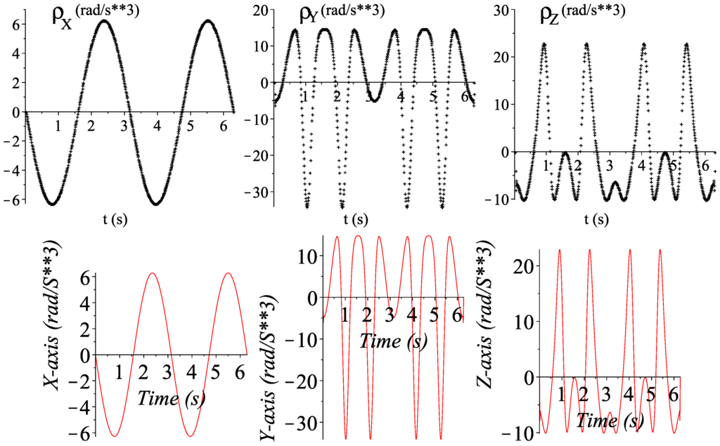
Figure 6.
Time history of the angular jerk of the knob as measured from the base using screw theory, upper plots, and its validation using an hybrid algorithm, lower plots.
8. Conclusions
In this work the kinematics up to the jerk analysis of a 2-dof parallel wrist is approached by means of the theory of screws. Simple and compact expressions to solve the velocity, acceleration and jerk analyses of the parallel wrist at hand are systematically obtained by taking advantage of the properties of reciprocal screws via the Klein form of the Lie algebra of the Euclidean group . Particularly, as far as the authors are aware, the jerk analysis in screw form of the parallel wrist under study has not been reported in previous works.
In order to show the application of the method a case study covering most of the topics treated in the contribution was included. Furthermore, the results of the velocity and acceleration analyses of the example were verified with the aid of commercially available software like ADAMS©.
Finally, the higher-order kinematic analyses of robot manipulators is more than an academic pursuit, e.g., it would be really usefully taking into account that human, automation and robot machines must collaborate in integrated systems [24].
Acknowledgments
This work was supported by DGEST and Conacyt of México.
Author Contributions
The method of analysis based on the theory of screws was translated into computer codes by Martín Caudillo-Ramírez and Ramón Rodríguez-Castro while Luciano Pérez-González built a virtual prototype of the parallel wrist using the special software ADAMS©in order to verify numerically the velocity and acceleration analyses of the case study. Jaime Gallardo-Alvarado is the first author of the contribution.
Conflicts of Interest
The authors declare no conflict of interest.
References
- Gosselin, C.M.; Angeles, J. The optimum kinematic design of a spherical three-degree-of-freedom parallel manipulator. Trans. ASME J. Mech. Transm. Autom. Des. 1989, 111, 202–207. [Google Scholar] [CrossRef]
- Carricato, M.; Parenti-Castelli, V. A novel fully decoupled two-degrees-of-freedom parallel Wrist. Int. J. Robot. Res. 2004, 23, 661–667. [Google Scholar] [CrossRef]
- Vertechy, R.; Parenti-Castelli, V. Synthesis of 2-DOF spherical US/UPS parallel mechanisms. In Advances in Robot Kinematics: Mechanisms and Motion; Lenarčič, J., Roth, B., Eds.; Springer-Verlag: New York, NY, USA, 2006; pp. 385–394. [Google Scholar]
- Li, W.; He, K.; Qu, Y.; Zhang, J.; Du, R. Hemisphere, a fully decoupled parallel 2-DOF spherical mechanism. In Proceedings of the 7th WSEAS International Conference on Robotics, Control & Manufacturing Technology, Hangzhou, China, 16–17 April 2007; pp. 301–306.
- Ueda, K.; Yamada, H.; Ishida, H.; Hirose, S. Design of large motion range and heavy duty 2-DOF spherical parallel wrist mechanism. J. Robot. Mech. 2013, 25, 294–305. [Google Scholar]
- Li, C.; Wu, Y.; Wu, J.; Shi, W.; Dai, D.; Shi, J.; Li, Z. Cartesian stiffness evaluation of a novel linebreak 2 DoF parallel wrist under redundant and antagonistic actuation. In Proceedings of the IEEE/RSJ International Conference on Intelligent Robots and Systems (IROS), Tokyo, Japan, 3–7 November 2013; pp. 959–964.
- Ayoub, M.M. Human movement recording for biomechanical analysis. Int. J. Prod. Res. 1972, 10, 35–51. [Google Scholar] [CrossRef]
- Morasso, P. Spatial control of arm movements. Exp. Brain Res. 1981, 42, 223–227. [Google Scholar] [CrossRef] [PubMed]
- Flash, T.; Hogan, N. The coordination of arm movements: An experimentally confirmed mathematical model. J. Neurosci. 1985, 5, 1688–1703. [Google Scholar] [PubMed]
- Uno, Y.; Kawato, M.; Suzuki, R. Formation and control of optimal trajectory in human multijoint arm movements. Biol. Cybern. 1989, 61, 89–101. [Google Scholar] [CrossRef] [PubMed]
- Gielen, C.C.A.M.; Vrijenhock, E.J.; Flash, T.; Neggers, S.F.W. Arm position constraints during pointing and reaching in 3-D space. J. Neurophysiol. 1997, 78, 660–673. [Google Scholar] [PubMed]
- Sparis, P.D.; Mouroutsos, S.G. A new matrix method for the kinematic analysis and motion simulation of planar mechanisms with lower pairs. Trans. ASME J. Mech. Transm. Autom. Des. 1984, 106, 429–436. [Google Scholar] [CrossRef]
- Dolgui, A.; Pashkevich, A. Manipulator motion planning for high-speed robotic laser cutting. Int. J. Prod. Res. 2009, 47, 5691–5715. [Google Scholar] [CrossRef]
- Arifur-Rahmana, A.K.M.; Feng, H.-Y. Effective corner machining via a constant feed rate looping tool path. Int. J. Prod. Res. 2013, 51, 1836–1851. [Google Scholar] [CrossRef]
- Zhang, L.; Bian, Y.; Chen, H.; Wang, K. Implementation of a CNC NURBS curve interpolator based on control of speed and precision. Int. J. Prod. Res. 2009, 47, 1505–1519. [Google Scholar] [CrossRef]
- Rico, J.M.; Gallardo, J.; Duffy, J. Screw theory and higher order kinematic analyisis of open serial and closed chains. Mech. Mach. Theory 1999, 34, 559–586. [Google Scholar] [CrossRef]
- Novàk, K.E.; Miller, L.E.; Houk, J.C. Kinematic properties of rapid hand movements in a knob turning task. Exp. Brain Res. 2000, 132, 419–433. [Google Scholar] [CrossRef] [PubMed]
- Ball, R.S. The Theory of Screws; Cambridge University Press: Cambridge, UK, 1900; (Reprinted 1998). [Google Scholar]
- Sugimoto, K.; Duffy, J. Application of linear algebra to screw systems. Mech. Mach. Theory 1982, 17, 73–83. [Google Scholar] [CrossRef]
- Rico, J.M.; Duffy, J. An application of screw algebra to the acceleration analysis of serial chains. Mech. Mach. Theory 31, 4, 445–457. [Google Scholar]
- Gallardo-Alvarado, J.; Orozco-Mendoza, H.; Rodríguez-Castro, R. Finding the jerk properties of multibody systems using helicoidal vector Fields. Proc. ImechE Part C 2008, 222, 2217–2229. [Google Scholar] [CrossRef]
- Esmaeili, M.; Gamage, K.; Tan, E.; Campolo, D. Ergonomic considerations for anthropomorphic wrist exoskeletons: A simulation study on the effects of joint misalignment. In Proceedings of the 2011 IEEE/RSJ International Conference on Intelligent Robots and Systems, San Francisco, CA, USA, 25–30 September 2011; pp. 4905–4910.
- Gallardo-Alvarado, J.; Aguilar-Nájera, C.R.; Casique-Rosas, L.; Pérez-González, L.; Rico-Martínez, J.M. Solving the kinematics and dynamics of a modular spatial hyper-redundant manipulator by means of screw theory. Multibody Syst. Dyn. 2008, 20, 307–325. [Google Scholar] [CrossRef]
- Kamali, J.; Moodie, C.L.; Salvendy, G. A framework for integrated assembly systems: Humans, automation and robots. Int. J. Prod. Res. 1982, 20, 431–448. [Google Scholar] [CrossRef]
© 2015 by the authors; licensee MDPI, Basel, Switzerland. This article is an open access article distributed under the terms and conditions of the Creative Commons Attribution license (http://creativecommons.org/licenses/by/4.0/).