1. Introduction
In quadrupedal mammals, the spine plays a key role in locomotion by contributing to stability and motion generation. Legged robots have always aimed to have the abilities to move on natural terrains and perform tasks in harsh environments. To achieve this, taking inspiration from biological structures and adding a flexible spine to robots is a promising design concept.
Typically, a robot spine design depends on its type and required functionality [
1,
2,
3,
4,
5], but most quadruped robots do not have a moveable spine structure [
6,
7,
8,
9,
10]. Such structures are simple, inexpensive, and easy to control, but are limited in the range of agile movements they generate. From a biomechanical perspective, the spine consists of passive components (vertebrae, ligaments, and intervertebral discs) and active components (muscles), where the passive structure provides mechanical support while muscles generate forces to produce motion [
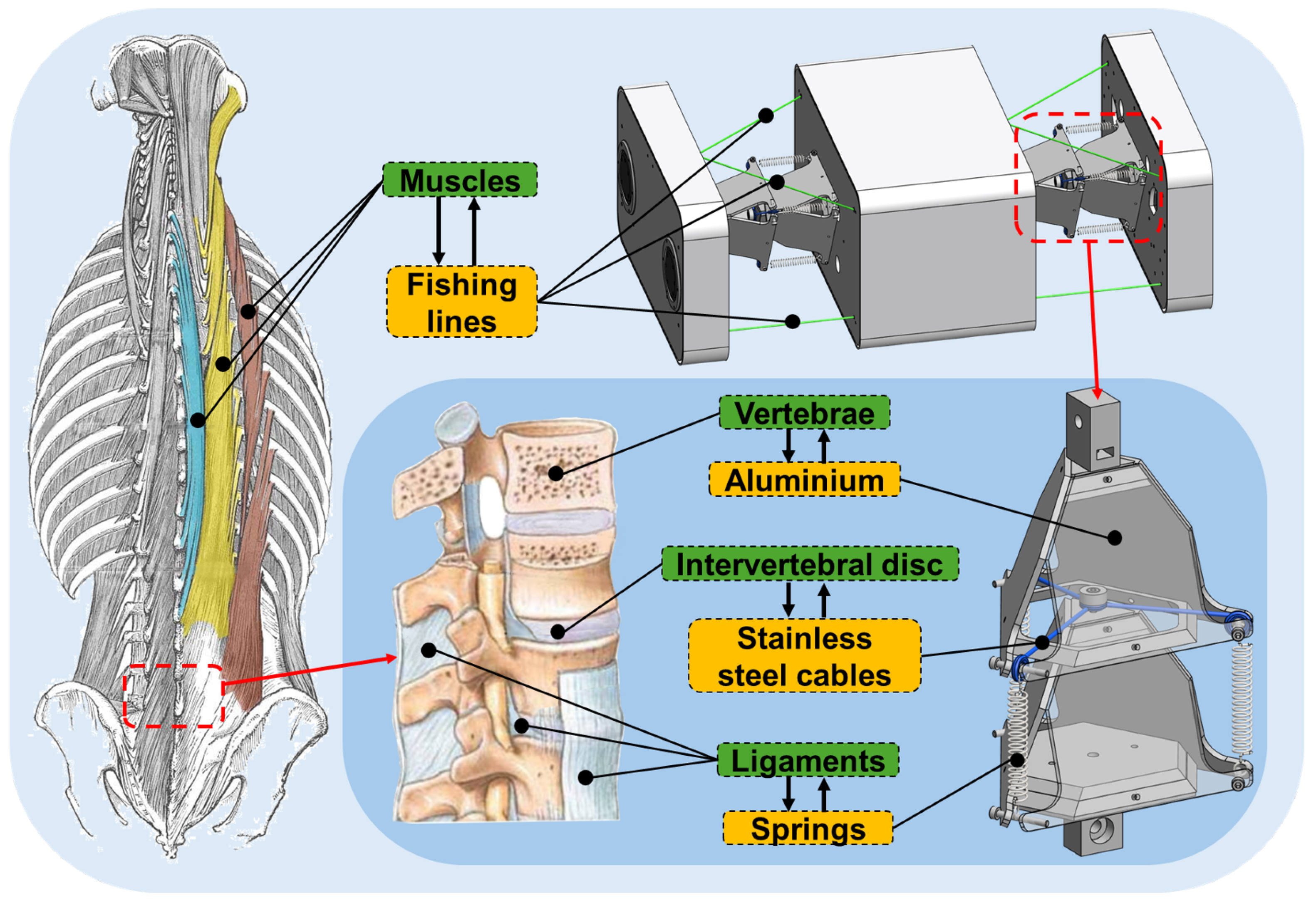
11]. However, many existing robotic spine designs do not explicitly distinguish between passive structural support and active actuation mechanisms. Accordingly, a bio-inspired tensegrity spine for a quadruped robot is proposed that consists of passive and active parts responsible for connection and is controlled separately (
Figure 1).
In the past decade, researchers have developed various spine structures for quadruped robots, which can be classified into passive and active based on their actuated mechanisms. The passive spine usually uses elastic and compliant elements arranged along the torso to connect the robot’s body segments. It has degrees of freedom (DOF) but is not actively controllable. Prior studies have shown that passive compliant spines improve energy efficiency and adaptability, particularly in sagittal-plane locomotion [
12,
13,
14,
15,
16,
17]. However, most designs are limited to a single DOF and lack active stiffness modulation. To exploit low-stiffness benefits, the passive spine proposed in this paper is designed as a tensegrity structure composed of stainless steel cables, springs, and aluminium plates.
Achieving enhanced locomotion performance requires not only appropriate compliance but also sufficient kinematic complexity of the spine structure. Incorporating multiple spine joints can increase the workspace of each leg and allow the generation of highly manoeuvrable motions [
18,
19,
20]. Compared to a single joint spine, a flexible multi-joint spine can improve both speed and stability for quadruped robots [
16]. Prior simulation studies suggest that two spine joints are sufficient to enhance stride length and emulate biologically inspired spine-driven locomotion, while additional joints provide diminishing returns [
21]. Therefore, the proposed bio-inspired tensegrity spine is designed with two joints.
In terms of active spine, it commonly provides a solid connection that can improve turning efficiency and speed [
22,
23], but the weight of the entire robot and the energy consumption are significantly increased with additional actuators. Studies also show that a robot’s stability during movement would be reduced with increasing rigidity of spinal connection [
13,
24]. These problems pose a challenge in designing a compliant actuated spine while minimising weight gain. A low-stiffness active spine can solve the above problems to a certain extent and is able to absorb external disturbance forces [
25,
26,
27,
28]. However, the additional perturbation caused by compliant elements also complicates accurate modelling, making it difficult to combine the spine with the legs to generate agile gaits. To solve this, the novel active spine outlined in this paper is driven by flexible wires and uses actuators to change its stiffness for different situations based on the pretension ratio (
) control method.
From a locomotion perspective, the ability to move simultaneously across multiple DOFs contributes significantly to agile gait generation, as the spines of animals often rotate through multiple DOFs at the same time to maintain balance and move through extreme terrains. Designing a structure with three DOFs that allows the spine to move in all three rotational directions simultaneously is another challenge worth solving. However, most existing quadruped robot spine designs have only one joint (
Table 1). This makes robots incapable of stably bearing loads during spine movement. Some robotic spines have multiple joints [
1,
16,
29,
30] but can rotate only in one or two directions. Among classes of structures, tensegrity structures promise to provide and control multiple DOF as a quadrupedal robot spine. It is a “tensile-integrity” structure and has unique physical properties that make it ideal for interaction with uncertain environments [
31], which lays the foundation for generating agile locomotion.
Among existing tensegrity-based spine designs for quadruped robots, Laika is the earliest representative [
35]. Its performance demonstrates the superiority of tensegrity structures in implementing multiple DOFs. Laika’s spine and most tensegrity spines are actuated by mounting motors on the tensegrity structure to control the wire length to change the movement for each DOF of the structure [
39]. However, this actuated method increases the structure’s weight, which is unsuitable for larger robots, as the movement of the spine will drive part of the leg movement. Many tensegrity structures used in robots are not fully tensioned, and some robots generate motions by adjusting the rope length of the tensegrity structure. These situations can lead to structural instability of robots while moving under load [
40]. Therefore, the proposed bio-inspired tensegrity spine uses an external drive to keep the passive spine in a tensioned state to maintain the compliance, controllability and load-bearing capacity of the spine.
Despite the promising results reported in existing flexible and tensegrity-based spine designs, several critical challenges remain in the design and control of quadruped robot spines, emerging from
Table 1: (a) achieving real-time variable stiffness in a compliant spine is still difficult due to the trade-off between adaptability and controllability; (b) while multi-joint spine structures have shown advantages in increasing stride length and improving dynamic stability, most existing designs remain limited to a single joint, restricting overall manoeuvrability and load-handling capabilities; (c) current spine designs rarely realise simultaneous motion across multiple DOFs, a feature frequently observed in biological systems that may contribute to agile and stable locomotion over complex terrain.
In contrast, the proposed bio-inspired spine integrates three key capabilities within a unified framework: (1) multi-joint structure with three rotational DOFs per joint, (2) simultaneous multi-DOF actuation, and (3) real-time stiffness modulation via pretension control. This combination may provide an adaptive foundation for future quadruped locomotion systems, particularly in scenarios requiring coordinated motion and improved adaptability to external disturbances.
Accordingly, this work proposes an integrated spine design and control framework that directly addresses the aforementioned challenges and makes the following contributions:
- (1)
A novel bio-inspired tensegrity spine structure with two joints and three rotational DOFs in different planes, enabling biologically inspired, compliant motion and coordinated multi-DOF actuation.
- (2)
A real-time stiffness control algorithm based on a wire-driven tensegrity mechanism with modulation of the pretension ratio, allowing the robot to adjust its spinal compliance during motion dynamically.
- (3)
An experimental validation of the spine design under loaded conditions demonstrates its stability with full 3-DOF simultaneous motion capability.
The rest of this paper is structured as follows:
Section 2 introduces the mechanism design of the proposed spine, including passive and active parts.
Section 3 presents the mathematical model and the variable stiffness control method based on pre-tension modulation.
Section 4 describes the complete control framework of the spine and demonstrates its capability for online stiffness adjustment.
Section 5 validates the control framework and the stiffness modulation method through experiments on the real bio-inspired tensegrity spine, and also verifies the spine’s ability to move in all three rotational DOFs and maintain structural integrity under different payloads by adjusting its stiffness.
Section 6 concludes the paper and provides an indication of further useful work.
2. Mechanism Design
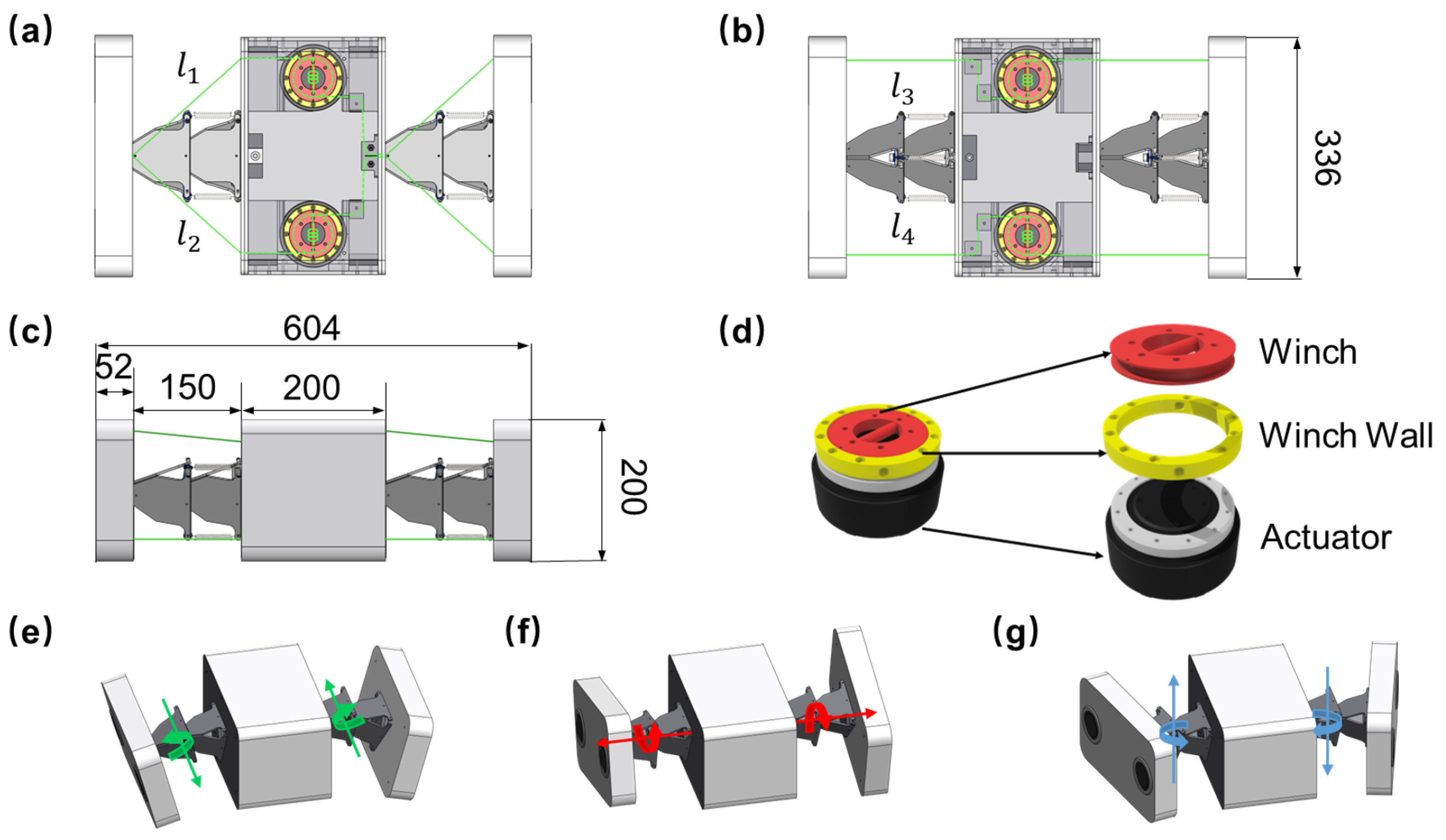
The novel bio-inspired spine outlined in this paper was specifically built for quadruped robots, aiming to provide a potential foundation for agile and stable locomotion. It is designed as three segments, and each pair of segments is connected by a tensegrity spine and four active wires, as shown in
Figure 2. The entire spine is made of PLA material by using 3D-printed, laser-cut acrylic sheets and CNC-machined aluminium to save costs and ensure strength and rapid prototyping.
The whole bio-inspired tensegrity spine is composed of active and passive parts, which has two joints with three rotational DOFs for each. The active part involves four Dyneema fishing lines wrapped on winches attached to actuators. Four high-torque-density actuators (Unitree [
41]) are placed in the middle segment to drive the entire spine. The passive part is a tensegrity structure that includes aluminium plates, springs and stainless steel wires. It can provide a strong connection between different body segments. The total length of the spine is approximately 0.6 m and the weight is about 8 kg. Actuated legs will be added to the front and rear parts in future work to investigate leg–spine coordinated locomotion.
2.1. Active Spine
In the field of robotics, most studies apply tensegrity structures for manipulation and end-effectors as active structures, achieving control by changing the length of the connecting wires on them [
42,
43]. This leads to a tensegrity structure that cannot be tensioned all the time, but can be flexibly controlled. A previous method used to drive a tensegrity spine is to mount motors on the tensegrity spine to adjust the lengths of connecting cables, and its rotation in the roll direction relies on a motor installed on the tensegrity structure [
35]. However, this method can only be used for small-size robots due to the size limitation of the spine and motors.
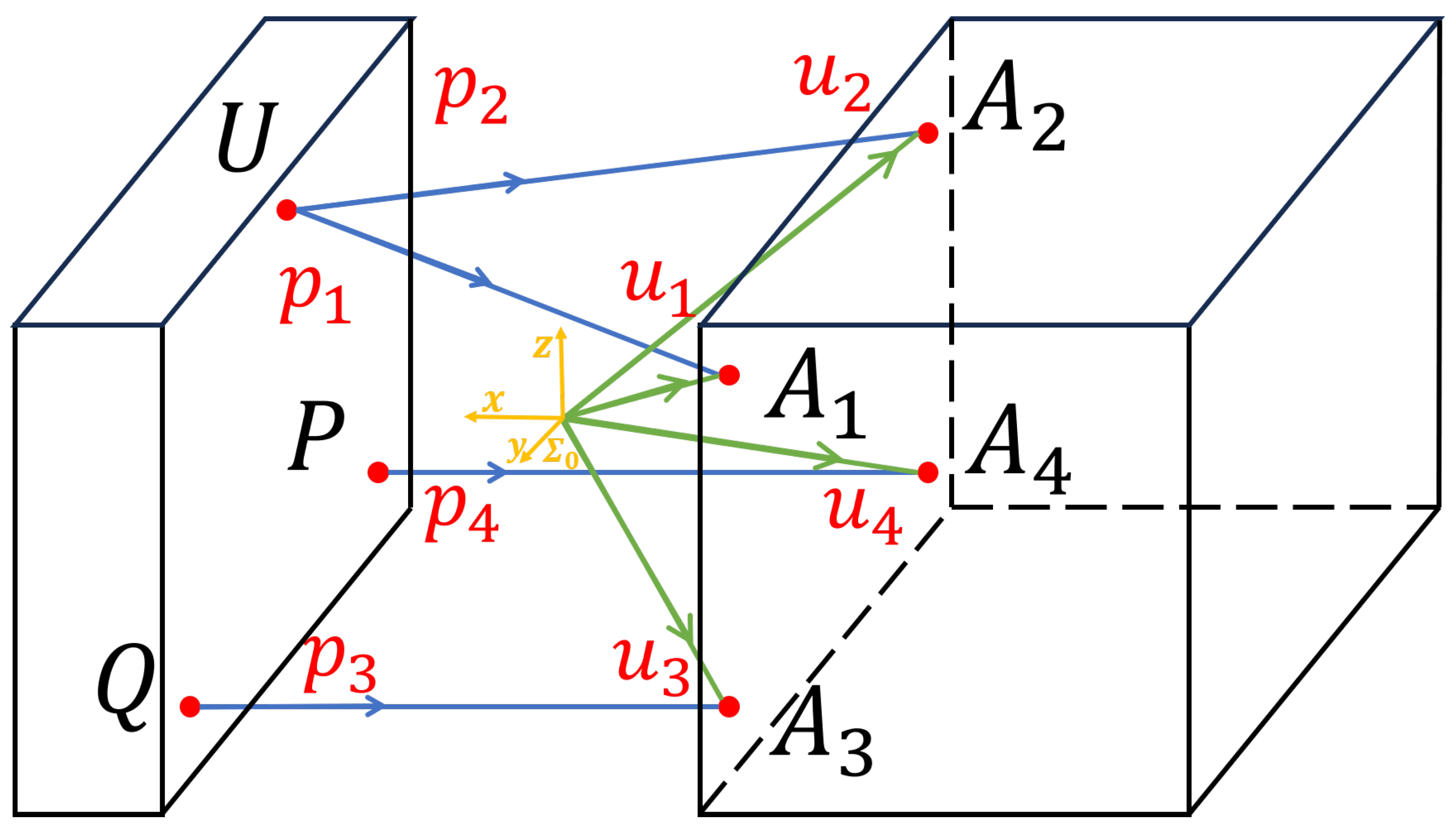
To utilise the properties of the tensegrity structure to generate spine movements, and actuate three degrees of rotational freedom in roll, pitch and yaw orientation in a bio-inspired way, the completely restrained parallel manipulator (CRPM) configuration is adopted. Four cables compose the active part of the spine, which are used to directly connect and actuate the relative movement of the adjacent body segments. It is a bio-inspired method in which the active part imitates the muscles around the vertebrae to drive the spinal joints to generate various movements.
The entire CRPM configuration of the spine consists of four 2 mm diameter braided polyethene lines with a load capacity of 250 kg. Adjacent body segments are connected by these wires and a tensegrity part, shown in
Figure 2. Four motors are placed in the middle body segment, and each controls one wire that is connected to the front and rear body at the same time. Such a configuration allows fewer actuators to actuate two joints with three DOFs by adjusting the length of active cables, but also results in a symmetrical motion of the two spines in the time and spatial domains.
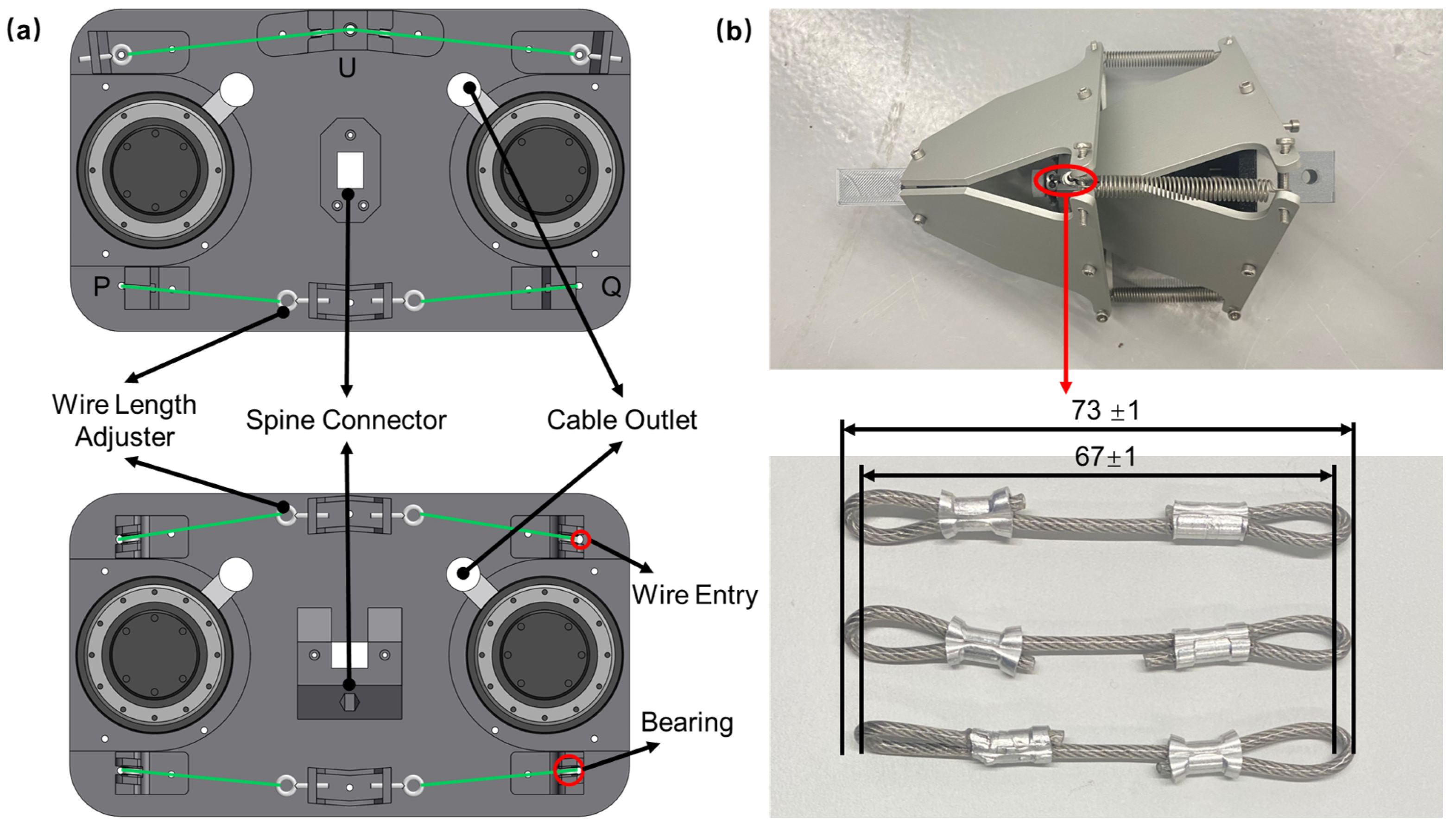
The active part of the wires is routed in the middle body segment as shown in
Figure 2b,c. Each actuator controls the length of a wire wound on its winch by rotation. There is a pulley to guide all the bends in the active wire. To prevent the wire wound on the winch from slipping when the actuator rotates, the wire is also wrapped around the bar in the middle of the winch to increase friction (
Figure 2d).
2.2. Passive Spine
In mammals, the spine serves only as a connection, and muscles around the spine generate torques or forces that control the spine to produce various motions. However, the vast majority of current quadrupedal robots with a spine lack bionic performance in their spine design. The spine in this paper includes passive and active parts, which are used to connect and drive the body segments.
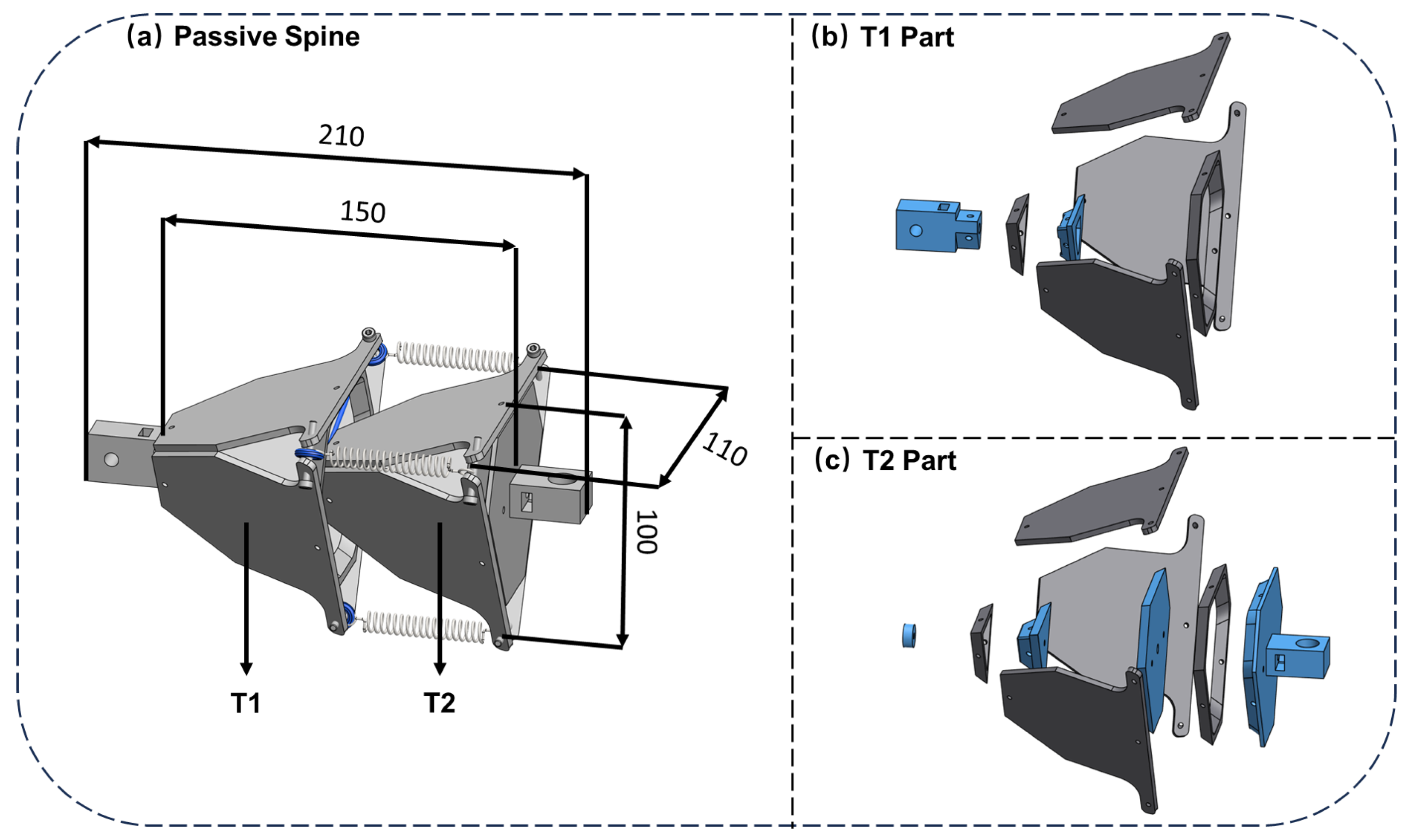
The passive spine has two sections of a tensegrity spine, T1 and T2 parts, that provide connections between each body segment as shown in
Figure 3. Each part is a regular tetrahedron structure that is assembled with M3 screws. Two of these parts are connected by springs and stainless steel wires to imitate the flexibility of biological spines. They are continuously pretensioned passively, where the springs are used to maintain the integrity of the structure, and stainless steel wires are used to constrain the translational displacement.
2.3. Assembly
Compared to rigid robots, wire-driven robots are cumbersome to assemble, especially in tensegrity structures with continuous tension and compressive components. Most robots with a tensegrity structure are under-tensioned, while others were equipped with driven parts on tensegrity parts, such as motors, to change the tension state. An under-tensioned tensegrity structure is easier to assemble than a fully-tensioned one, but it is unsuitable for use as a connecting part. The bio-inspired tensegrity spine has two identical passive parts that are tensegrity structures used to connect front and rear body segments. Those require a fully tensioned state to provide a stable connection and withstand the load. Each passive part consists of CNC-machined aluminum plates, springs and stainless steel wires, and is manually assembled using M3 screws. In theory, the front and rear passive parts are exactly the same length which leads to the distance between different body segments also being the same. However, the main assembly error for passive parts is the length of handmade stainless steel wires that are shown in
Figure 4b. The two ends of the stainless steel wires are crimped into a ring by aluminium crimping sleeves. The total length after production is about 73 mm and the internal length is about 67 mm. The length of the stainless steel wire is made about 1 to 2 mm greater than the theoretical value for easy assembly.
The active part includes four fishing lines to control the bio-inspired tensegrity spine. Each fishing line connects with an actuator, and its two ends are connected to the front and rear body segments. However, manual assembly and production of active fishing line length will inevitably have small errors, which will cause the front and rear spines not to be tensioned at the same level. Thus, the wire length adjuster is designed for adjusting the fishing line length between body segments. Each fishing line end is connected with a wire length adjuster that is an M3 screw with a hook. The thread length of the M3 screw with a hook is approximately 17 mm, which is able to adjust ±10 mm for each active fishing line. After the spine is tensioned, multiple adjustments are made based on the IMU readings of the front and rear body parts to achieve the same movement of the front and rear spine parts. This design reduced the assembly error for the length of the fishing line of the active parts.
After assembly, the spacing between body segments is determined by the length of the passive spine, which is in turn defined by the stainless steel wires. The lengths of the active cables connecting the front and rear body segments determine the synchronisation of their movements and tension. Measurements after assembly and tensioning indicate that the overall spine length error is approximately 3 cm (
Table 2). This deviation does not affect the resulting control accuracy or performance, since the mathematical model can be calibrated to the real prototype. The main factor influencing control accuracy is the difference between the lengths of the front and rear passive spines after tensioning. Through repeated adjustments, this difference can be reduced to within 2–3 mm.
Overall, due to the excellent characteristics and biomimetic performance of the structure, the engineering problem of assembly is worth solving. The tensegrity structure as a robot spine has the following advantages compared with existing rigid actuated spines:
- (1)
Its independent three degrees of rotational freedom can be simultaneously actuated, providing a larger motion capability and greater flexibility for coordinated spinal movements.
- (2)
Tensegrity structures have higher structural efficiency compared with rigid structures, which allows a greater payload ratio for the robot.
- (3)
The inherent compliance of the tensegrity spine improves the robustness of the robot for situations such as external impacts and hazards.
- (4)
The flexibility of the tensegrity spine can potentially improve the energy efficiency of the robot and absorb external perturbations.
4. Spine Control and Tension
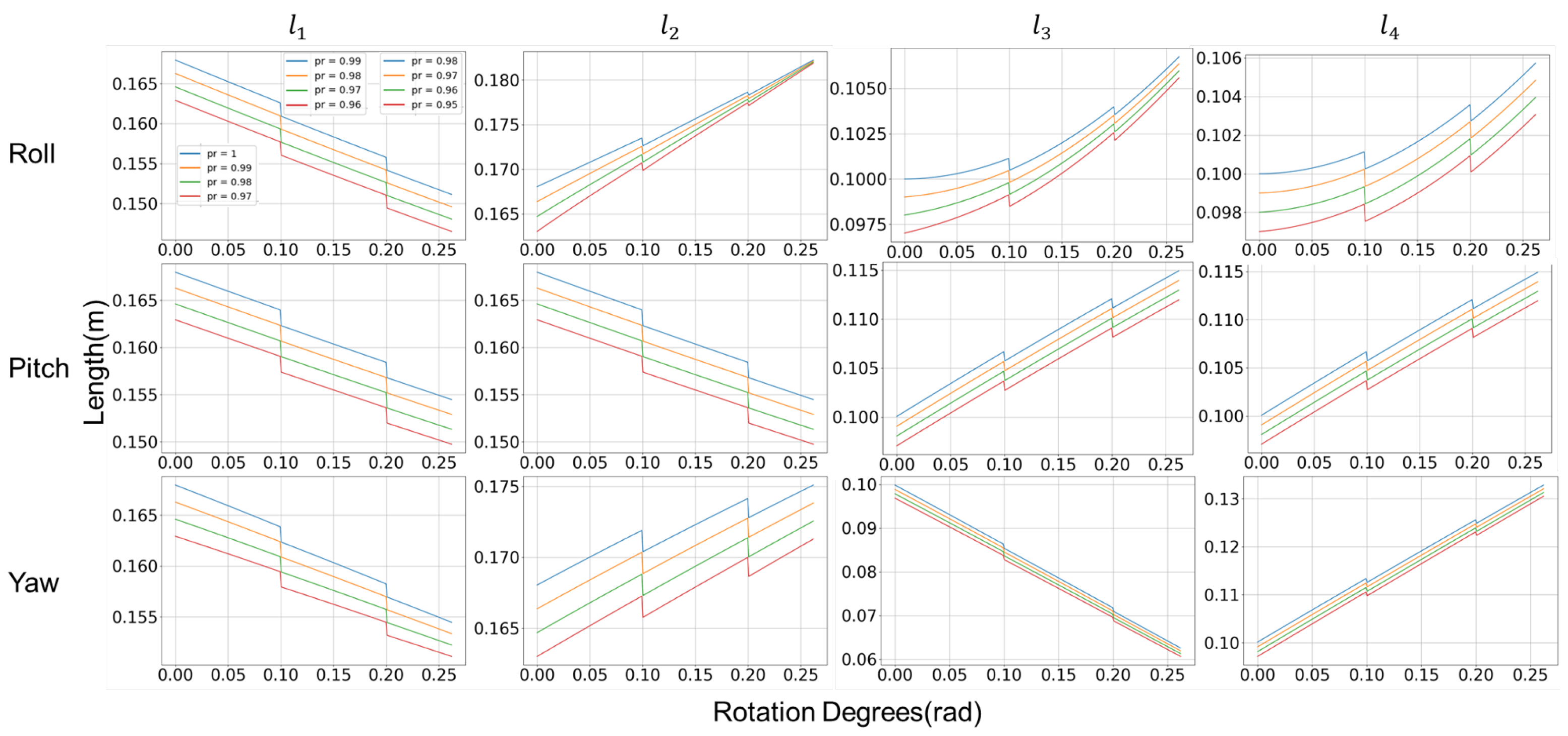
In this section, a bio-inspired tensegrity spine control framework is proposed using the pretension-based control method. The framework allows the spine to generate single- and multi-DOF movement according to user input. Also, it can change the stiffness during movement to deal with different environmental situations. An automatic tension process has also been proposed to achieve an identical initial tension state for each use. Finally, the framework keeps tension consistent, and motions generated based on different pretension ratios were demonstrated in simulation.
4.1. Control Framework
The proposed spine control framework provides a real-time mechanism for simultaneous posture and stiffness control.
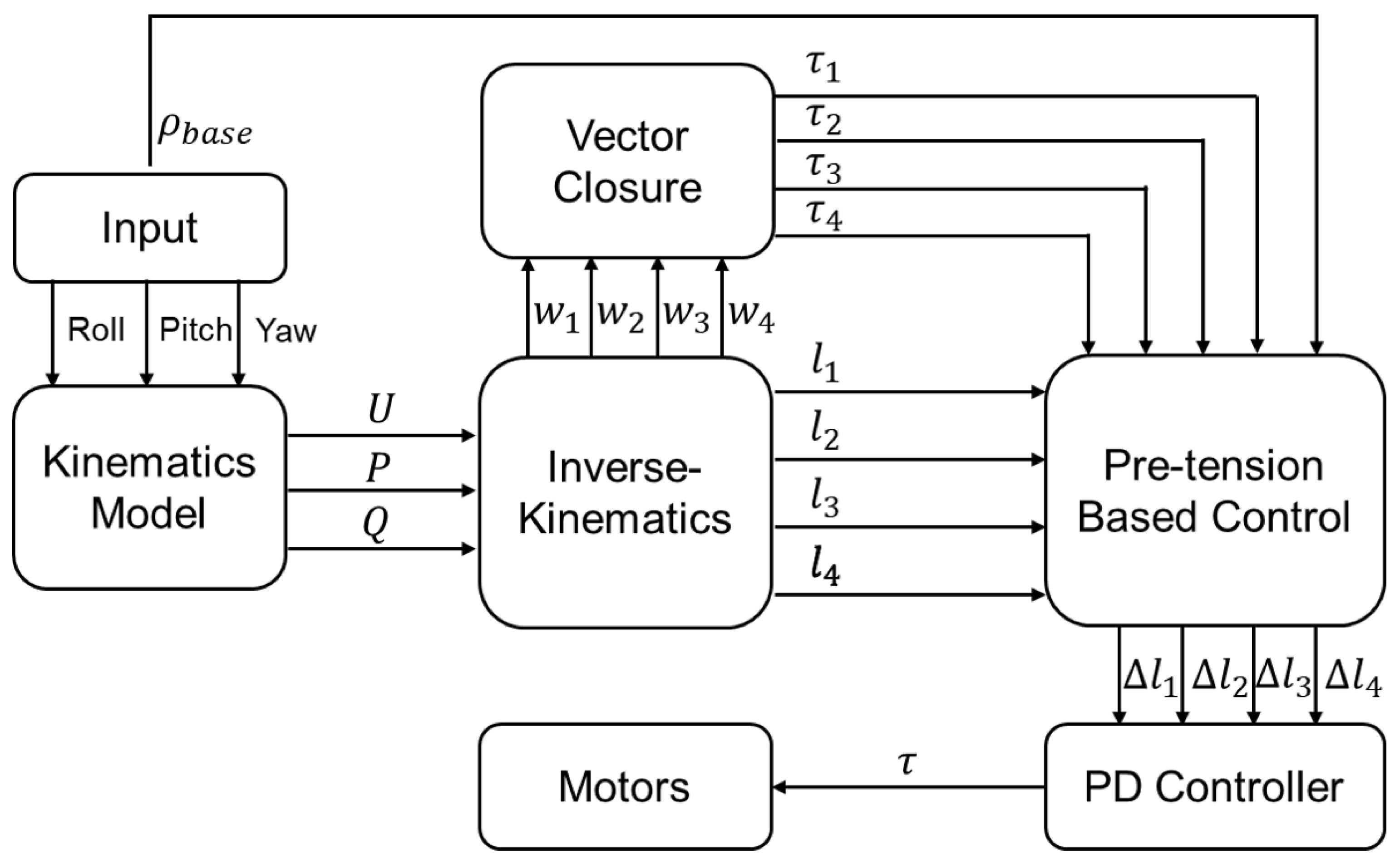
Figure 7 illustrates the overall data flow and module relationships from the desired posture to the motor drive signal within one time step.
The input to the framework includes the desired rotation angles in roll, pitch, and yaw directions, as well as the pretension ratio for the spine. The kinematics model takes those rotation angles to calculate the new position of the spine defined by geometric parameters . An inverse-kinematics module then takes as input and determines the target wire lengths, , and wire vectors, , for the new posture. The vector closure is used to calculate the torque applied to each wire based on the target posture, ensuring that forces remain in static equilibrium. Based on these torques and the user-specified pretension ratio, a pre-tension control module computes the incremental length adjustments for each wire. This sequence of computations yields variable-stiffness control: by adjusting cable pretension, the framework achieves both the desired posture and the prescribed stiffness level.
Throughout this process, the control algorithm essentially evaluates the difference between each wire’s new target length and its original length as dictated by the desired angles and pretension ratio. By continuously updating these length differences, the system allows users to modulate spine tension in real time, accommodating different motion requirements or external disturbances while maintaining stable posture control.
4.2. Automatic Tension Process
The spine is in a slack configuration when the system is powered off. To ensure a consistent initial tension level each time the spine is controlled, an automated tensioning process is executed before starting the spine.
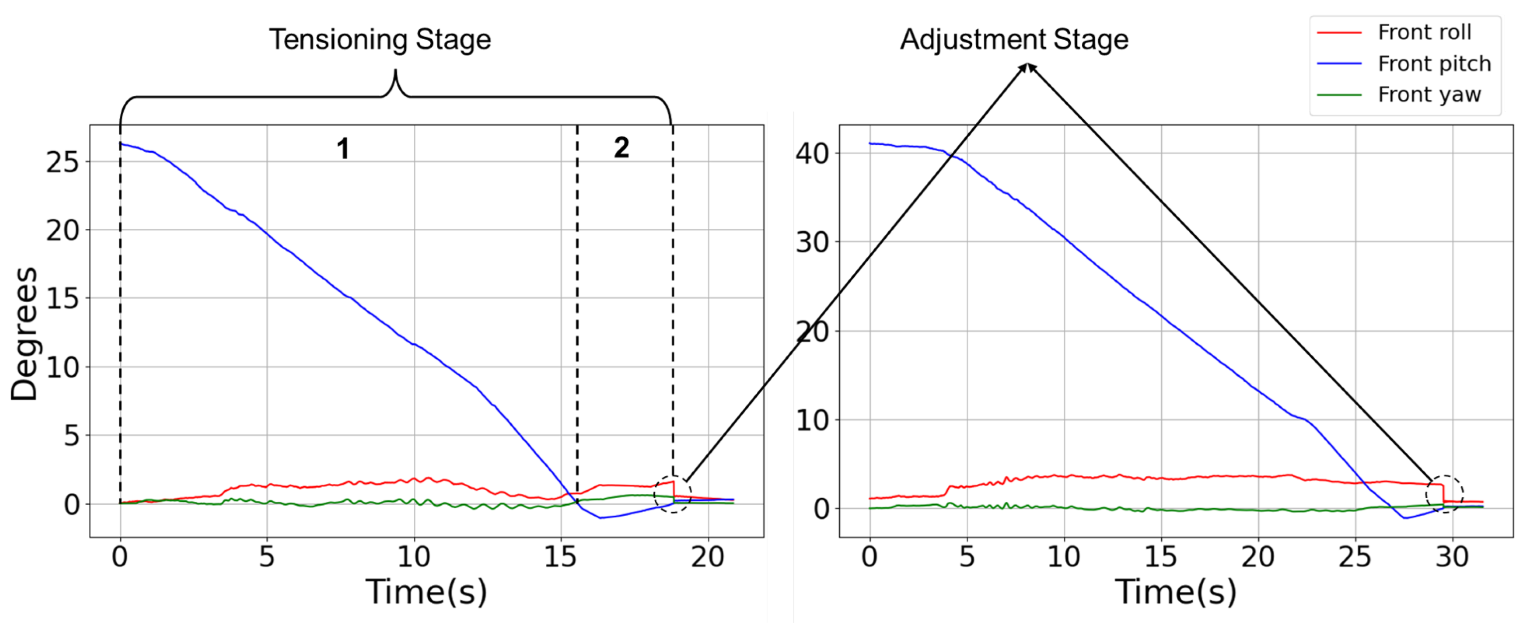
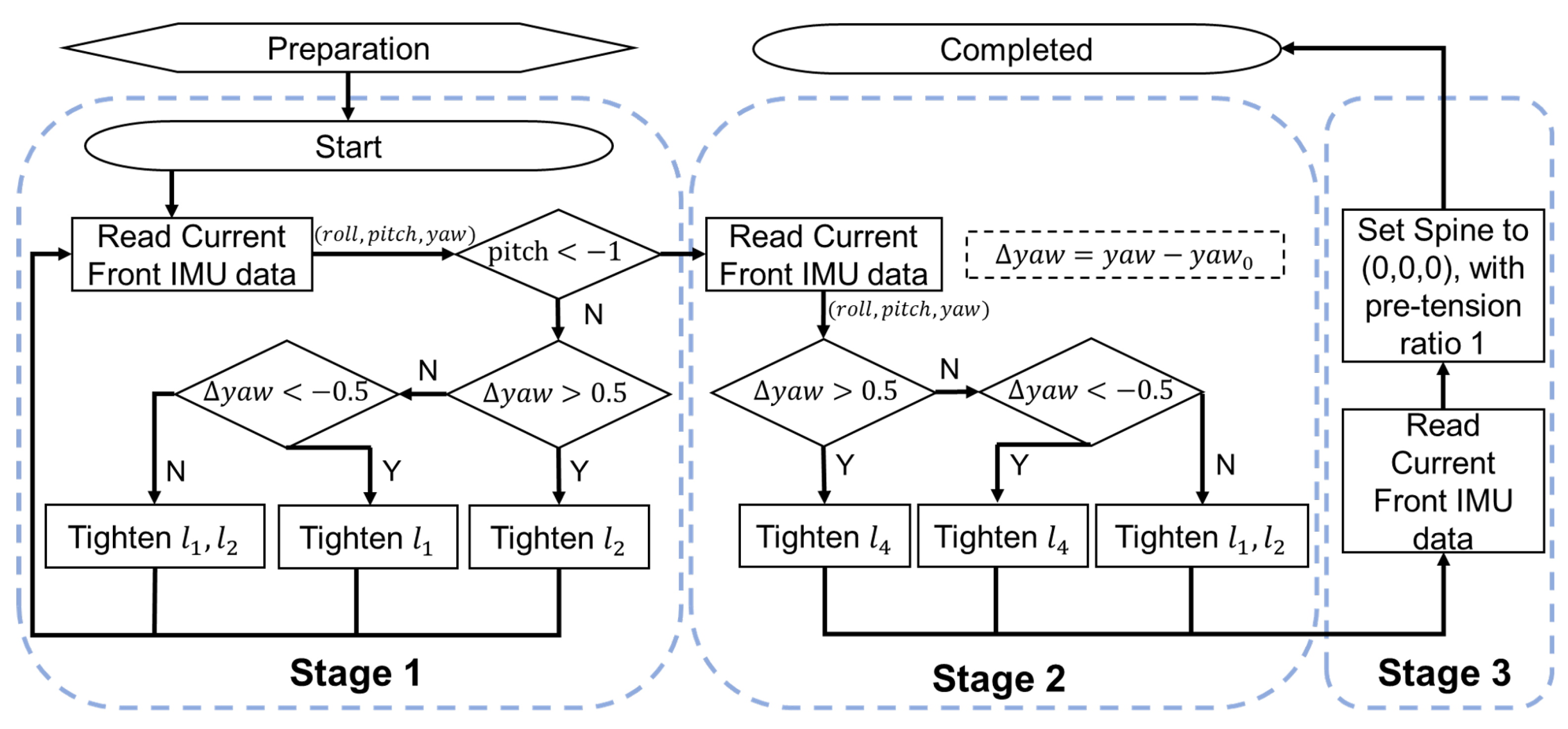
Figure 8 shows the flow chart of the automatic tensioning process, which incrementally tightens all wires until the spine reaches a predefined default tension state. After this process, the pretension ratio of wires is effectively zeroed, and the different body segments are aligned in roll, pitch and yaw directions, which are all nominally zero. Experimental validation confirms that each orientation axis is held within
degrees of its target during startup, providing a reproducible initial condition for subsequent motion control.
The automatic tensioning process consists of a preparation stage, two tensioning stages and an adjustment stage.
(1) Preparation stage: In the preparation stage, the four active fishing lines of the spine need to be set to a slack state. The front and rear body segments are aligned with the middle body segment in the yaw direction; i.e., there is no angle difference in the yaw direction. The pitch and roll directions do not need to be strictly aligned. In addition, the height of the middle body segment should not be lower than the front and rear body segments.
(2) Tensioning Stage 1: In this stage, the two motors that control the two wires and above the spine tighten the two wires at a reduced speed until the angle of the front spine is −1 degree. During this process, the IMU data will be acquired in real time to monitor the deviation of the spine in the yaw direction, so that its error is within 0.5 degrees.
(3) Tensioning Stage 2: The second tensioning stage is to tighten the two lower wires and . Since the front and rear spines are both raised by 1 degree in the pitch direction, contracting the two lower ropes to pull the spine back to 0 degrees can tighten the spine. As with the first tensioning stage, the yaw direction rotation is kept within degrees while tensioning the lower wires.
(4) Adjustment Stage: Finally, the current spine angle will be obtained through the IMU reading, and the spine will be adjusted based on the reading to keep the error in all directions within degrees. The pretension ratio is set to 1.
Figure 9 shows the process of automatic tensioning of the spine in different initial states. At the beginning of tensioning, the rope below the spine is in a relaxed state, and the rope above begins to tighten. The preparation stage ensures that the spine has no deviation in the yaw direction but may have some deviation in the roll direction. In the first stage, the two active ropes above the spine begin to tighten until the spine lift height is −1 degree in the pitch direction. Then the rope below is tightened until it returns to zero degrees in the pitch direction. The lifting height can be adjusted according to the actual situation of the spine. If the stiffness of the spine is low, it can be lifted 2 or 3 degrees in the first stage and then to the second stage. After the second stage, it can be seen that the spine has an adjustment in the roll, pitch and yaw directions, so that all three directions are set to 0 degrees, that is, the initial default state. At this point, the tensioning of the spine is complete. All subsequent experiments in this paper will follow this automatic tensioning process, so that it is tensioned to the same state for control after each startup.
5. Experimental Results
In this section, the mathematical model and control framework of the spine are verified through several experiments. Single- and multi-DOF movements have been conducted to validate the movement ability of the bio-inspired tensegrity spine by comparing the desired and measured angles. Additionally, experiments were conducted to investigate the effect of spinal stiffness on its integrity under different load conditions.
5.1. Experiment Setup
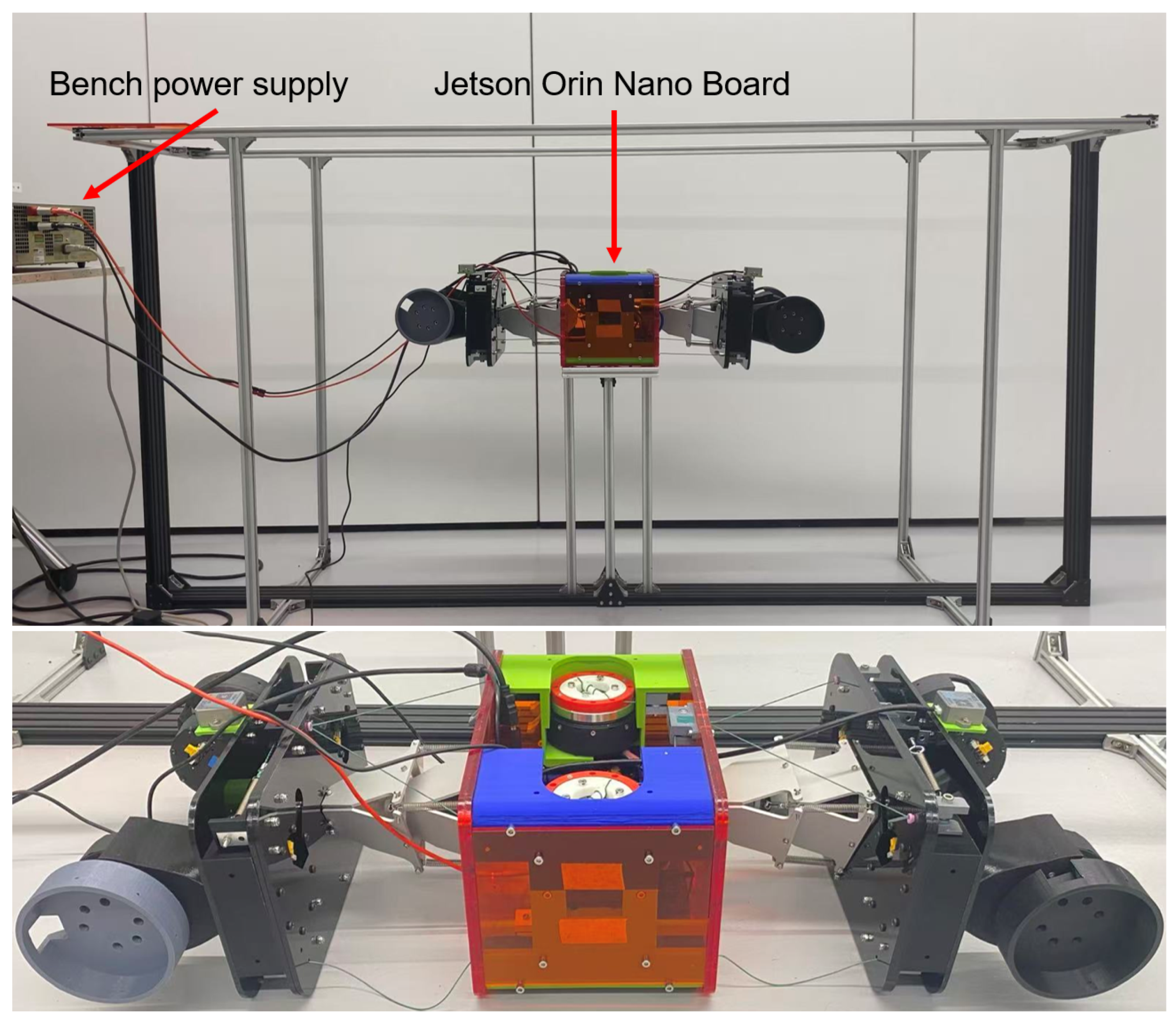
In quadruped robots with a two-joint spine, the mid-body can act as a relatively stable reference during locomotion. Accordingly, to focus on the relative motion of the front and rear segments, the mid-body was fixed while the remaining parts were suspended. A gantry with a size of 2 m × 0.5 m × 1 m (length × width × height) was built for testing the tensegrity spine, as shown in
Figure 10. The middle body segment is placed on a platform, with front and rear parts hanging off the two ends. Two IMUs are mounted in the top centre of the front and rear segments in the same direction, and have a maximum frequency of 300 Hz. A Jetson Orin Nano board is placed in the middle of the body to collect data from two IMUs and control the spine. All actuators and the onboard PC are powered by a bench power supply that is placed on the left side of the gantry but not shown
Figure 10. The frequency of spine control and IMU data collection is 200 Hz, and the speed of spine movement was set to a low range for safety. The actuator uses PD position control with parameters
and
. The IMU coordinates are used to measure the angles of the front and rear spine joints that are consistent and the same as those modelled by the control method as coordinate
shown in
Figure 5.
Through verification of the leg–spine coordinated movement in simulation, it was found that spinal movement greater than 10 degrees can easily cause the quadruped robot to fall. The best spine movement is around 5 degrees. Therefore, the single-DOF control experiment of the real spine limits the movement in all directions to within 15 degrees, and multi-DOF movements are limited to 5 degrees.
Since the pre-tension ratio only affects the spine stiffness, and its different values do not theoretically affect the control accuracy, in all movement experiments, the pretension ratio is set to the default value 1.
5.2. Single-DOF Spine Movement
To evaluate the basic motion capability of the spine, experiments were first conducted for single-DOF movements and all results are from five repeated experiments. The spine was commanded to perform both linear and sinusoidal trajectories in roll, pitch, and yaw directions independently. The experimental setup for linear motion is as follows:
- (a)
Roll rotation: while and are zero. The error in roll directions is calculated by ;
- (b)
Pitch rotation: while and are zero. The error in pitch directions is calculated by ;
- (c)
Yaw rotation: while and are zero. The error in yaw directions is calculated by .
and represent the desired angle and the actual angle, respectively, in degrees, obtained from the IMUs at time t. All linear motions have a time period of 6 s at 200 Hz. The linear motion speed is set to degrees per second. The spine will be automatically tensioned with before each experiment to ensure that the spine is in the same tension state.
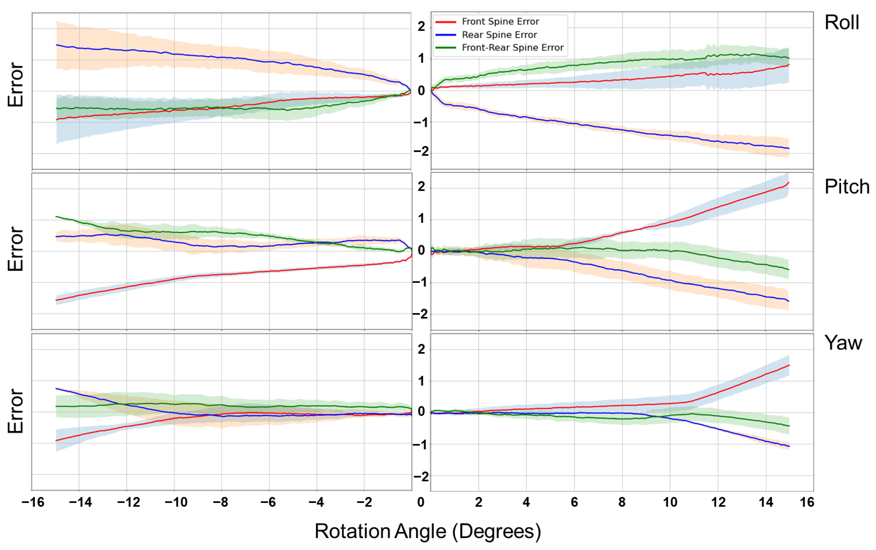
The results for linear trajectories are presented in
Figure 11. In all three directions, the tracking error of the front and rear joints remained within 1 degree for motions up to 10°, and the maximum error observed was approximately 2 degrees in the roll direction. The relative error between the front and rear segments was generally below 0.5 degrees, reaching 1 degree only during negative pitch motion.
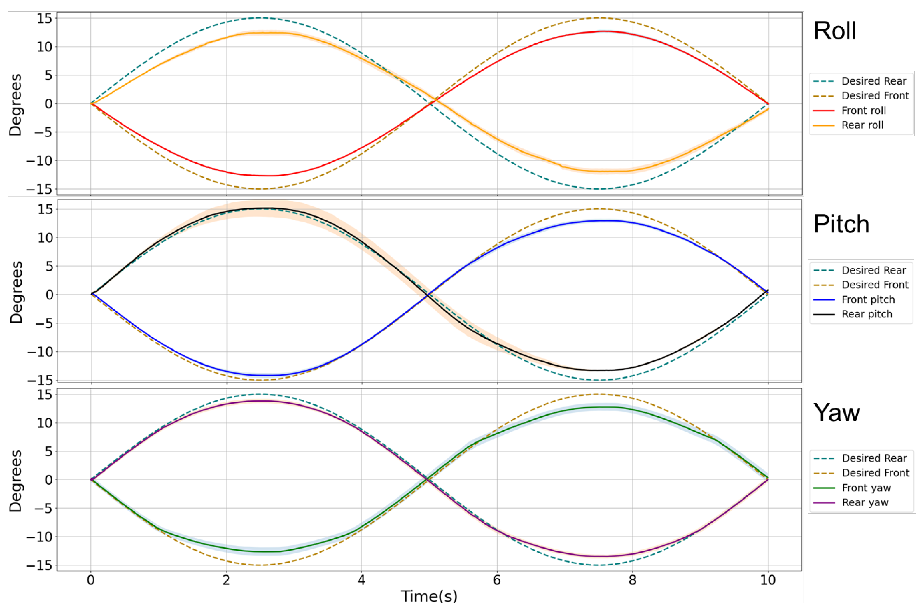
Nonlinear movement in roll, pitch and yaw directions were also validated. The spine rotated with a sinusoidal function within the range of degrees. The trajectory in each direction is as follows:
- (a)
Roll rotation: while and are zero. The error in roll directions is calculated by ;
- (b)
Pitch rotation: while and are zero. The error in pitch directions is calculated by ;
- (c)
Yaw rotation: while and are zero. The error in yaw directions is calculated by .
Sinusoidal trajectories are shown in
Figure 12. Across all directions, the tracking error remained within 2 degrees, with most values under 1 degree. At the end of each trajectory, the spine returned to its neutral configuration with residual error within 0.5 degrees.
These results confirm that the proposed controller achieves stable and accurate trajectory tracking in single-DOF motions. The consistency between the front and rear segments demonstrates the effectiveness of the pretension-based control in maintaining symmetry of motion. Although the error in the roll direction was slightly larger than in pitch and yaw, the overall accuracy remained within 2 degrees, which is sufficient for integration with quadruped locomotion, where typical spinal excursions are less than 10 degrees. This experiment validates the feasibility of the control framework for fundamental motion tasks and establishes a baseline for subsequent multi-DOF and load-bearing evaluations.
5.3. Two-DOF Spine Movement
Multi-DOF movement is an important feature of the bio-tensegrity spine. These experiments verify the ability of the spine to move simultaneously in two different directions. Three combinations were tested: roll–pitch, roll–yaw, and pitch–yaw. For each case, the spine moved from 0 degrees to the target angle and back to 0 degrees at a constant speed of degrees per second. The target angles, , in different directions for each combination are .
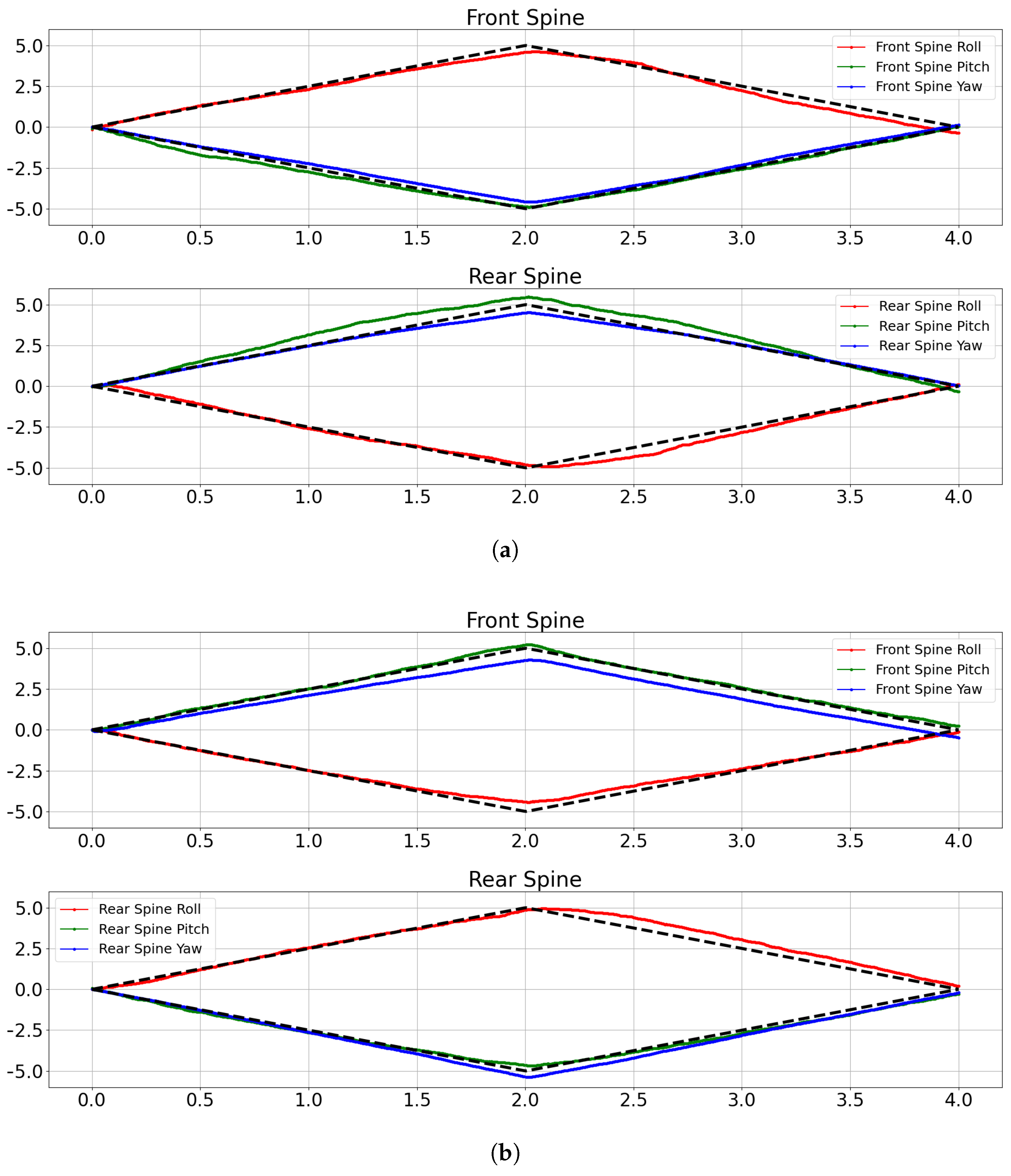
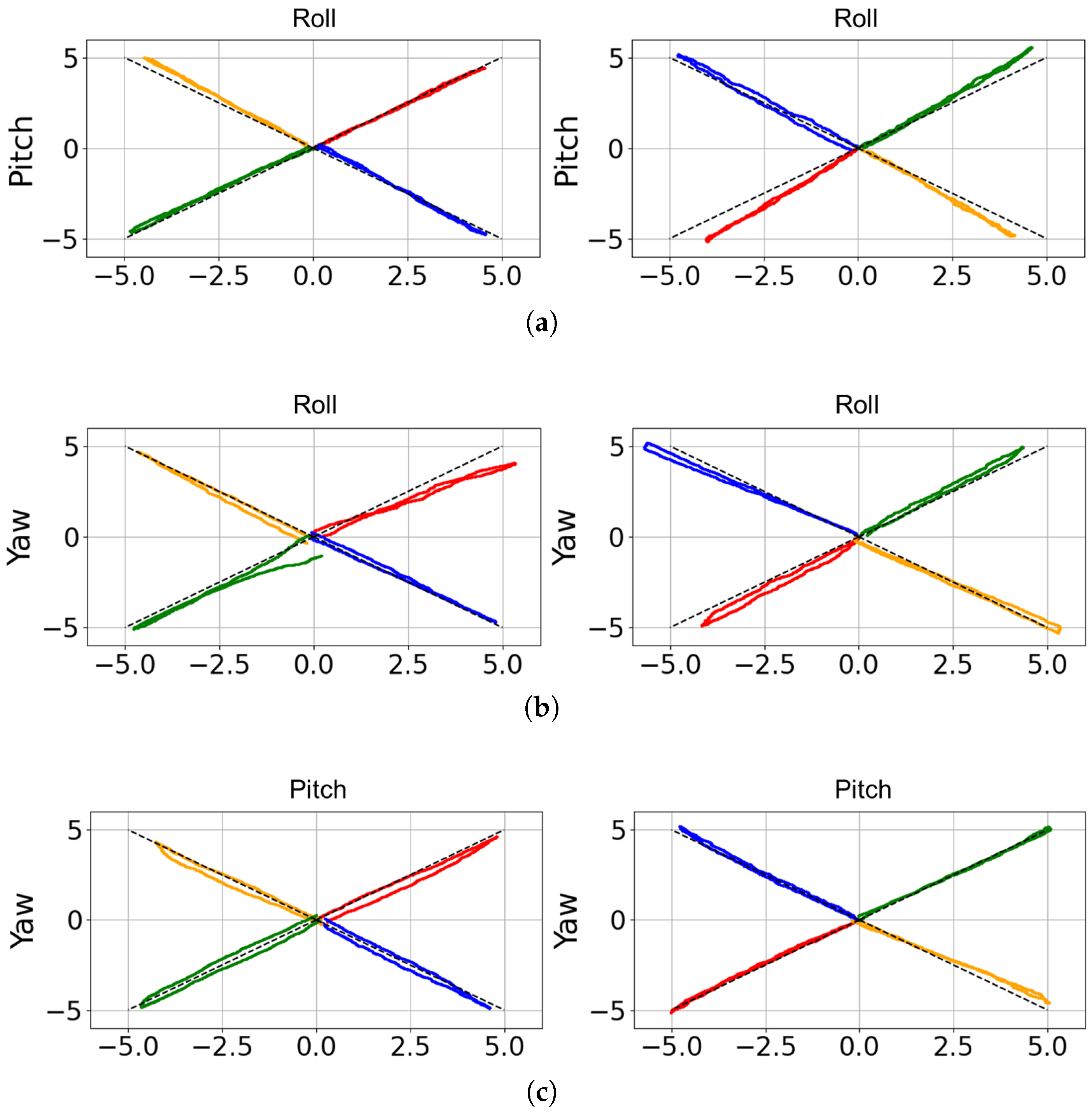
As shown in
Figure 13, the spine successfully tracked the combined trajectories in all three 2-DOF cases with high accuracy. The average tracking error in both DOFs was below 0.5 degrees, and the maximum deviation did not exceed 1 degree. Furthermore, the relative error between the front and rear segments was consistently less than 0.5 degrees across all cases, indicating stable synchronisation. The spine also reliably returned to its initial position after each movement.
A comparison of the results across different directions shows that the pitch–yaw combination achieved the highest accuracy, with motion errors of approximately 0.5° (
Figure 13c). In contrast, when roll motion was involved, the accuracy was slightly reduced, primarily due to limited spinal displacement in the roll direction (
Figure 13a,b). This behaviour arises from the passive tensegrity structure, in which the springs introduce higher impedance in the roll direction.
These results confirm that the proposed controller can effectively generate coupled multi-DOF motions without significant performance degradation compared to the single-DOF case.
5.4. Full 3-DOF Spine Movement
To validate the full motion capability of the spine, experiments were conducted with three degrees of freedom actuated simultaneously. The spine was commanded to follow two trajectories of ±5° in roll, pitch, and yaw simultaneously over a time of 4 s:
where the target sets are defined as
Figure 14 shows the measured trajectories compared to the desired inputs. Despite the increased complexity of controlling all three DOFs simultaneously, the system maintained reliable performance. The tracking error in each DOF was generally below 1 degree, and the maximum error observed was about 1.2 degrees. Importantly, the front and rear segments moved synchronously, confirming that the tensegrity-based design preserved structural integrity during multi-DOF operation. Moreover, from the results, the spine can not only track the pre-set trajectory well, but also has high repeatability accuracy, with an error of approximately 0.3 degrees.
These results confirm that the spine can execute complex three-DOF trajectories with high accuracy and repeatability. The low tracking errors and consistent synchronisation between front and rear segments demonstrate the effectiveness of the pretension-based control strategy under fully coupled motion. The bio-inspired tensegrity spine lays a foundation for generating complex and agile locomotion patterns in future quadruped robots.
To summarise, all of the results demonstrate the correctness of the mathematical model and the accuracy of the control algorithm. Although some errors still exist during the movement, the robot’s motion error is generally kept within 1.2 degrees. Furthermore, the front and rear spine errors are significantly reduced to within 0.5 degrees due to the adjustable mechanism. One possible origin of the errors is the inaccuracy under large deformations where nonlinear structural effects become more significant [
46].
5.5. Payload
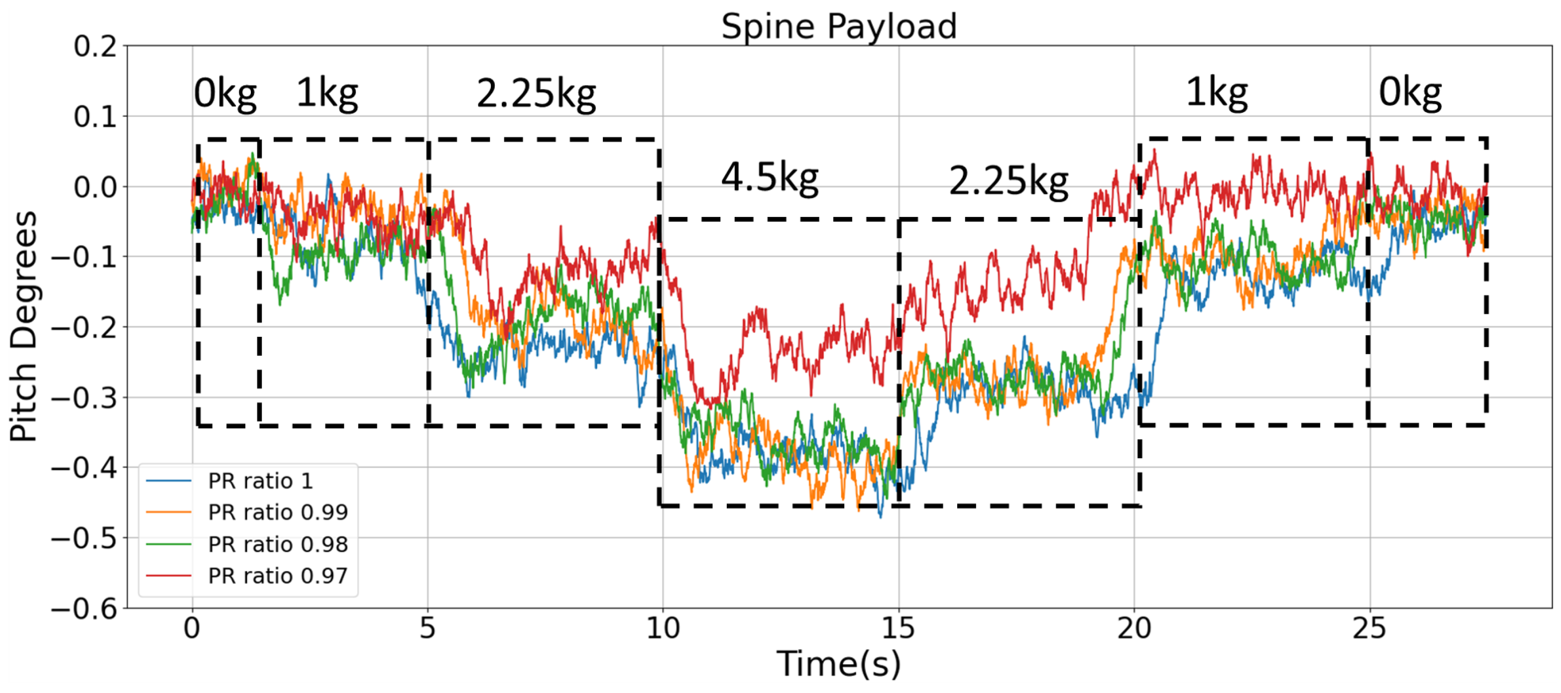
In addition to verifying the motion control performance, experiments were carried out to evaluate the structural load-bearing behaviour and variable stiffness performance of the spine under controlled static loading conditions. In this study, the stiffness characterisation is intended as a comparative experimental evaluation of the variable stiffness behaviour based on load–deformation responses under identical loading conditions. The spine was supported at the front and rear ends, while external weights were applied incrementally at the middle segment. The pretension ratio was varied between 0.97 and 1.0 to represent different stiffness levels. The objective was to compare structural deformation under varying payloads and stiffness settings. Before each experiment, the spine is automatically tensioned to the same tension level as the default stiffness.
As illustrated in
Figure 15, for each stiffness configuration, the deformation of the spine increased with increasing payload. When the pretension ratio was 1, the angular deviations became larger, and the structure exhibited greater fluctuations during load transitions. When the spine stiffness is highest, with
, the range of spine angle variation is minimal, with fluctuations within 0.3 degrees. For other stiffness configurations, the fluctuations in this load experiment are within 0.5 degrees. It can also be seen that the spine exhibits almost no deformation when subjected to loads under 1 kg. The spine also returns to its default angle when all loads are removed. This experiment not only demonstrates the spine’s strong load capacity but also demonstrates its ability to adapt stiffness to varying load weights through a pretension-ratio-based control algorithm.
Based on the load–deformation curves obtained in the payload experiment, the effective stiffness can be estimated from the steady-state deformation under the same external load. As shown in
Table 3, taking the 4.5 kg loading condition as an example, the average deformation decreases from approximately 0.43 degrees at
to
degrees at
. By approximating the stiffness as inversely proportional to deformation, the normalised stiffness increases from about
to
, indicating a significant enhancement as the pretension ratio decreases. This result suggests a consistent relationship between the pretension ratio and the effective stiffness, where lower
values lead to higher stiffness. The trend is not strictly linear, with stiffness increasing more noticeably at lower pretension ratios.
These findings demonstrate that the proposed spine can maintain structural stability under external loading, while the stiffness adjustment mechanism effectively modulates compliance. Lower pretension ratios reduce deformation and improve resistance to payloads, whereas higher ratios allow more flexibility at the cost of greater deflection.
Overall, the results confirm that the bio-inspired tensegrity spine not only enables accurate active motion in multiple DOFs but also preserves its structural integrity when subjected to payloads. The ability to dynamically tune stiffness according to operating conditions is a key advantage of the proposed design compared to conventional rigid or passive spines.
6. Conclusions and Future Work
Since its creation by artist Kenneth Snelson in 1948, the tensegrity structure has been gradually used in engineering applications such as architecture and robotics. This paper has presented the design, modelling, control and validation of a novel bio-inspired tensegrity spine based on a tensegrity structure and inspired by biomechanics. The proposed spine integrates a passive tensegrity part and an active wire-driven part to achieve two joints with three rotational DOFs each, while allowing online stiffness modulation through a pretension-based control method. The design provides both active motion and inherent compliance, which are essential for generating versatile and stable locomotion on quadruped platforms.
Extensive experiments were conducted to evaluate the performance of the proposed spine. The results demonstrate accurate motion tracking in single-DOF movements, stable coordination in multi-DOF cases, and reliable performance during simultaneous three-axis motions. In addition, payload experiments confirm that stiffness modulation effectively maintains structural stability under varying loads. These results validate that the proposed structure provides both controllability and compliance while maintaining structural integrity under payload. However, the stiffness characterisation presented in this work mainly focuses on experimentally validating the variable stiffness behaviour achieved through pretension modulation. Future work will investigate analytical stiffness modelling and rigorous stiffness characterisation methods for the compliant tensegrity structure.
The outcomes of this study suggest that combining tensegrity architectures with variable stiffness control establishes a feasible design paradigm for quadruped spines. Such a design may contribute to movement diversity, stability on irregular terrains, and adaptability to payload variations. In addition, the vector closure condition may also provide a useful interpretation for antagonistic muscle coordination in biological systems, which could be an interesting direction toward identifying deeper bionic principles. Future work will focus on integrating the bio-inspired tensegrity spine into a fully functional quadruped platform to investigate coordinated leg–spine locomotion, exploring learning-based methods for adaptive gait generation, and further improving the assembly process and scalability for real-world deployment.