1. Introduction
The progressive ageing of the global population, together with the rising prevalence of neurological and musculoskeletal disorders, has led to an increasing demand for technologies capable of assisting, monitoring, and restoring human motion [
1]. Motion impairments associated with ageing, stroke, orthopaedic injuries, and neurodegenerative diseases significantly reduce autonomy and quality of life, while simultaneously increasing healthcare costs [
2,
3,
4,
5]. In this context, motion assistance and rehabilitation systems have emerged as a key research area within wearable devices [
6,
7,
8].
Modern rehabilitation paradigms increasingly emphasise continuous monitoring, personalisation, and home-based therapy [
9]. Traditional clinical approaches rely on periodic assessments performed in controlled laboratory or hospital environments, often using sophisticated instrumentation such as optical motion capture systems, force platforms, or instrumented treadmills. While these systems provide highly accurate kinematic and kinetic measurements, their high cost, lack of portability, and requirement for specialised personnel limit their applicability outside laboratory settings. As a result, there is a growing interest in compact, wearable sensing technologies capable of providing reliable motion information in real-world environments [
10,
11,
12].
Wearable motion monitoring systems have been widely investigated for assisting or assessing upper-limb and lower-limb movements, balance control, gait analysis, and joint-specific rehabilitation [
13,
14,
15]. These systems are often integrated into assistive devices such as exoskeletons, orthoses, cable-driven robots, and soft wearable mechanisms. In such applications, accurate motion estimation is critical not only for a posteriori analysis but also for real-time control, adaptive assistance, and safety monitoring.
In recent years, wearable sensing technologies have rapidly evolved, enabling continuous monitoring of human posture, gait, and biomechanical parameters outside laboratory environments. Advances in flexible electronics, miniaturised sensors, and embedded signal processing have facilitated the development of wearable systems capable of long-term physiological and biomechanical monitoring for applications in rehabilitation, sports science, and preventive healthcare [
16,
17]. Emerging wearable platforms increasingly integrate multiple sensing modalities, including inertial sensors, strain sensors, and biochemical sensors, enabling the comprehensive monitoring of both biomechanical and physiological parameters. Recent studies have explored smart textiles, electronic skin technologies, and wearable biosensors capable of continuous health monitoring and human–machine interaction [
18,
19]. Within this context, wearable sensing technologies are also being widely investigated for posture monitoring, gait analysis, and mobility assessment, providing valuable tools for clinical diagnostics, rehabilitation monitoring, and telemedicine applications [
20].
Among available motion measurement technologies, inertial measurement units (IMUs) have gained particular attention due to their low cost, small size, low power consumption, and ease of integration [
21,
22,
23]. IMU-based systems enable the continuous tracking of orientation and movement without the need for external infrastructure, making them especially suitable for home-based rehabilitation and long-term monitoring [
24,
25,
26,
27,
28]. However, IMUs inherently suffer from sensor noise, bias, and drift, particularly in yaw estimation, which necessitates robust sensor fusion and signal processing techniques [
29,
30,
31,
32,
33,
34].
Recent studies have demonstrated the growing use of wearable IMUs for estimating ankle joint kinematics and enabling portable motion monitoring outside laboratory environments [
35]. Systematic reviews also report that IMU-based systems can achieve clinically acceptable agreement with optical motion capture systems, typically showing root mean square errors below approximately 5° for ankle joint range of motion during locomotion tasks [
36,
37]. Nevertheless, many existing studies primarily focus on algorithmic reconstruction accuracy or controlled gait analysis experiments, often relying on multi-sensor setups or external computing infrastructure [
38,
39,
40].
Alternative wearable measurement solutions have been proposed in the literature, including flexible strain sensors [
41], pressure-sensitive insoles [
42], electromyography-based systems [
43], and vision-based approaches using RGB or depth cameras [
44,
45]. While each of these technologies presents specific advantages, they also introduce limitations related to accuracy, usability, calibration complexity, sensitivity to environmental conditions, or cost [
46,
47,
48]. Consequently, no single solution currently satisfies all the requirements for affordability, robustness, simplicity, and accuracy needed for widespread deployment in assistive and rehabilitation contexts.
Within this broader research landscape, the present work focuses on the development of a self-contained wearable kinematic sensing unit designed for integration into rehabilitation and assistive robotic systems. The approach proposed in this work emphasises the development of a self-contained wearable sensing module designed for integration within rehabilitation and wearable robotic systems. The proposed angle measuring device (AMD) combines magnetometer-free 3D orientation estimation, explicit yaw drift mitigation, and full-plane optical validation within a low-cost architecture of about 50 €. Moreover, the device operates as an independent measurement unit capable of recording motion data directly on an SD card, allowing use without external devices or complex technological interaction. This design makes the system particularly suitable for deployment in rehabilitation scenarios and for users with limited technological familiarity, while remaining adaptable to different joints and wearable assistive devices.
In this framework, the ankle joint represents a particularly relevant application for the experimental validation of the proposed sensing approach [
49,
50,
51,
52]. Although the ankle plays a fundamental role in balance, locomotion, and posture control, it is also one of the most frequently injured joints and is critically affected by ageing-related decline [
53,
54]. Nevertheless, the methodology and sensing approach addressed in this work are not limited to ankle motion analysis. Instead, the proposed wearable sensing module is conceived as a general-purpose kinematic measurement unit that can be embedded within different motion-assistive or rehabilitation systems [
55].
The present study focuses on the experimental validation of a compact, low-cost IMU-based wearable system for real-time multi-degree-of-freedom motion monitoring. The system is validated against a laboratory-grade optical motion capture system, Optitrack V120 Trio [
56], which serves as a reference standard. Unlike many existing studies that concentrate on a single plane of motion or qualitative comparisons, this work evaluates three-dimensional joint kinematics across multiple anatomical planes, providing a comprehensive quantitative assessment of accuracy, robustness, and practical usability.
2. Materials and Methods
This work addresses the challenge of accurately estimating foot kinematics like angular displacement, angular velocity, and linear acceleration during ankle movements using a compact and wearable sensing and angle measuring device (AMD), which was designed at the LARM2 Lab of Tor Vergata University. The proposed system aims to provide reliable ankle mobility measurements comparable to those obtained with high-end optical motion capture systems, while preserving a low-cost, portable, and compact design. Such characteristics are essential to extend the applicability of the system beyond laboratory environments and enable its integration into a wide range of motion-assistive and rehabilitation devices.
Rather than being conceived exclusively for ankle rehabilitation, the proposed sensing device is designed as a general-purpose wearable measurement unit that can be embedded within different assistive, therapeutic, or monitoring systems for motion analysis. The primary objective is to develop a simple, lightweight, and non-invasive device capable of acquiring accurate kinematic data without introducing discomfort, pain, or mechanical interference with the user’s natural movement or with the main assistive mechanism to which it may be coupled.
Table 1 summarises the main functional, mechanical, and usability requirements that guided the design of the wearable sensing device. The requirements were defined to ensure accuracy, comfort, robustness, and compatibility with a wide range of assistive and rehabilitation systems, while preserving low cost and ease of use.
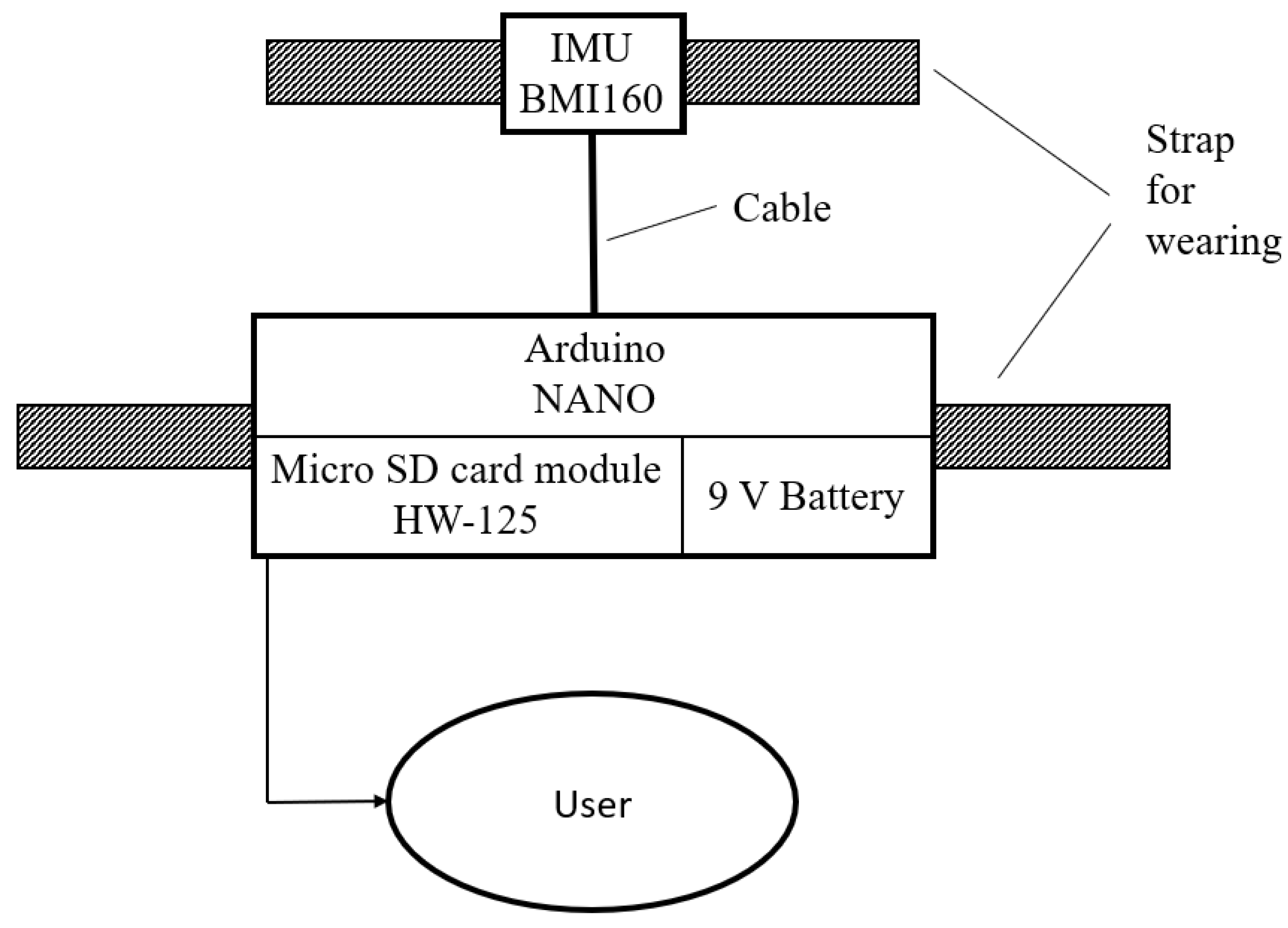
Figure 1 shows the conceptual diagram of the AMD.
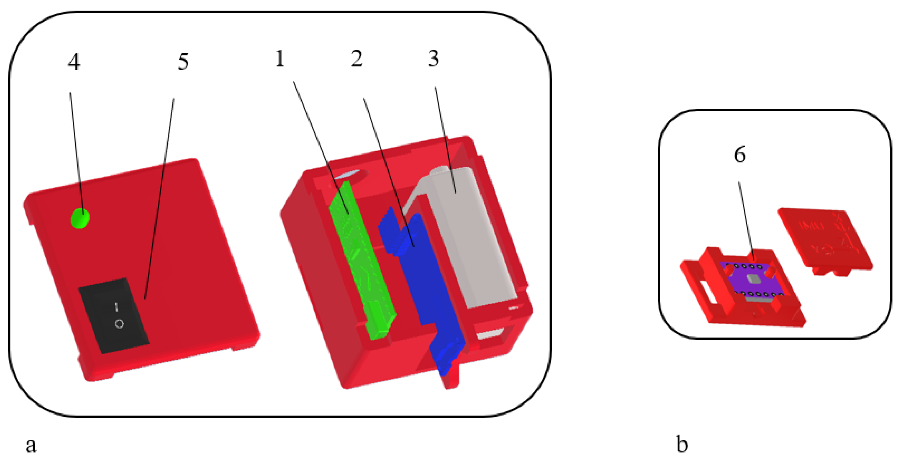
Figure 2 shows the CAD design of the small housing containing the AMD.
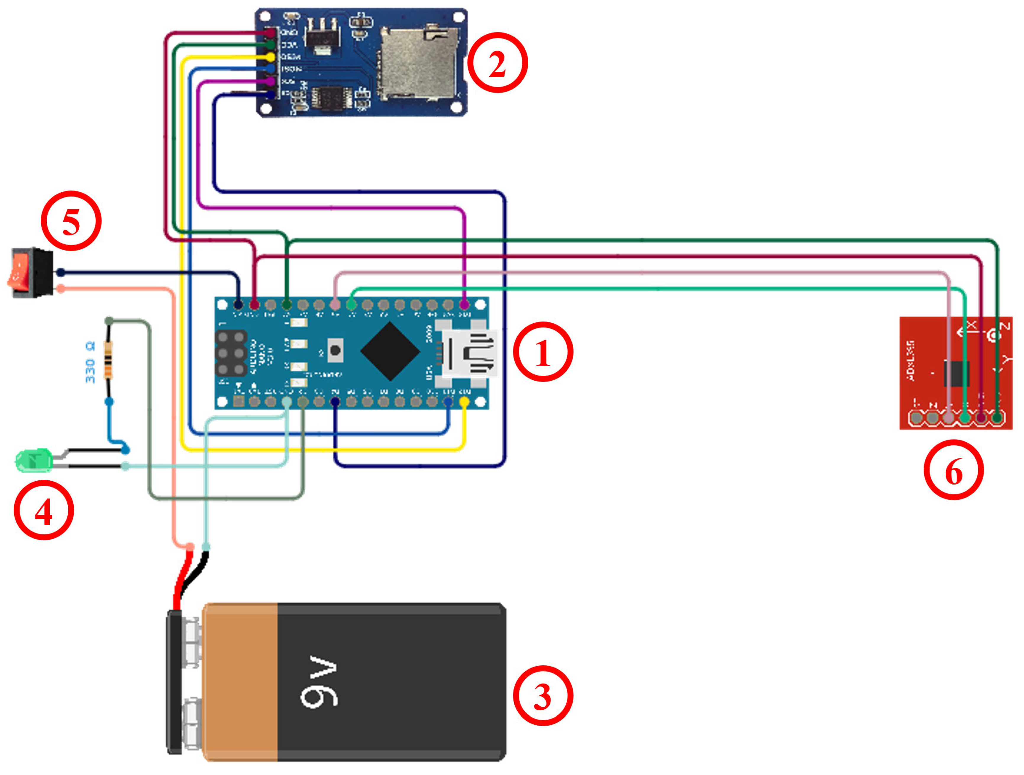
The wearable device has a total mass of approximately 50 g, dimensions of 54 mm × 60 mm × 35 mm (big box) and a cost of around 50.00 €. It is powered by a rechargeable battery that allows continuous data acquisition for up to 16 h, making it suitable for extended monitoring sessions. The system architecture is based on a custom-designed enclosure realised through 3D modelling and additive manufacturing techniques. The enclosure houses an inertial measurement unit (BMI160) [
57] (
Figure 2b 6), an Arduino Nano microcontroller [
58] (
Figure 2a 1), a 9 V power supply (
Figure 2a 3), a micro-SD card module (HW-125) [
59] (
Figure 2a 2), an LED (
Figure 2a 4) and an on/off switch (
Figure 2a 5), enabling onboard acquisition and storage of motion data.
Particular attention was devoted to the mechanical and ergonomic design of the enclosure to ensure robustness, ease of use, and seamless integration with the anatomical parts of the user. The casing is designed to securely accommodate all electronic components while maintaining a compact form factor and minimising bulk. Separate internal compartments are adopted to prevent undesired component movement and potential damage. Additionally, the enclosure provides direct access to the SD card slot and USB port to simplify data transfer, device programming, and recharge. Dedicated mounting features are included for all essential hardware elements, namely the Arduino Nano board, micro-SD module, battery, status LED with current-limiting resistor, on/off switch, and IMU sensor.
To ensure user comfort and practicality in real-world applications, the device is ergonomically shaped and attached to the foot using a Velcro strap, allowing fast positioning and removal without inducing pressure points or restricting ankle motion. Data acquisition is performed at a sampling frequency of 30 Hz, which is adequate for capturing both slow and dynamic ankle movements.
The sampling frequency of 30 Hz was selected as a compromise between motion capture fidelity, onboard data logging reliability, and device power consumption. While several IMU-based gait analysis studies adopt higher sampling frequencies (e.g., 100 Hz or above) [
60,
61], particularly for dynamic locomotion tasks such as running, the dominant frequency content of controlled ankle rehabilitation movements is typically below a few hertz. According to sampling rate analyses reported in the recent literature [
62], IMU sampling frequencies around 100 Hz are recommended for walking and higher frequencies for running; however, slower movements can be accurately captured at lower sampling rates when the dominant motion frequencies remain well below the Nyquist limit.
Recorded data are stored in text format on the SD card, facilitating subsequent post-processing, visualisation, and integration with external computational tools.
Although data were stored on the SD card during the experimental campaign to preserve the complete dataset for benchmarking against the MoCap reference system, at a sampling rate of 30 Hz, the hardware architecture supports real-time data acquisition and processing. The offline processing pipeline adopted in this study was specifically implemented to enable rigorous validation of the sensing approach through detailed comparison with the optical motion capture system. It should be noted that this sampling frequency is mainly limited by the data writing process to the SD card rather than by the sensing or processing capabilities of the device. When using alternative communication interfaces such as Wi-Fi or Bluetooth for data transmission, higher sampling rates can be achieved, enabling real-time monitoring and feedback applications. Therefore, the real-time capability of the proposed procedure can be ensured by replacing the SD card logging with direct data streaming or onboard processing, enabling immediate computation and transmission of the estimated kinematic variables for real-time monitoring and feedback applications.
The experimental campaign of this work was carried out at the Intelligent Robotics Lab of Swansea University, Swansea, UK, with the participation of 16 healthy subjects (12 males and 4 females) according to a protocol approved by the Ethics Committee of Swansea University with Research Ethics Approval Number 1 2024 11492 10405. The subjects voluntarily participated in this study. The inclusion criteria were the absence of diseases or injuries that could affect ankle movements and age between 20 and 60 years. Inclusion or exclusion criteria were not imposed regarding height, weight, or gender. The main characteristics of the 16 subjects included in the experimental campaign are listed in
Table 2.
The tests on ankle movements were carried out according to the following procedure:
- -
Repetition of 3 complete movements on the sagittal plane as plantarflexion and dorsiflexion;
- -
Repetition of 3 complete movements on the frontal plane as eversion and inversion;
- -
Repetition of 3 complete movements on the transverse plane as abduction and adduction.
Each participant repeated the 3 steps for both the right foot and the left foot.
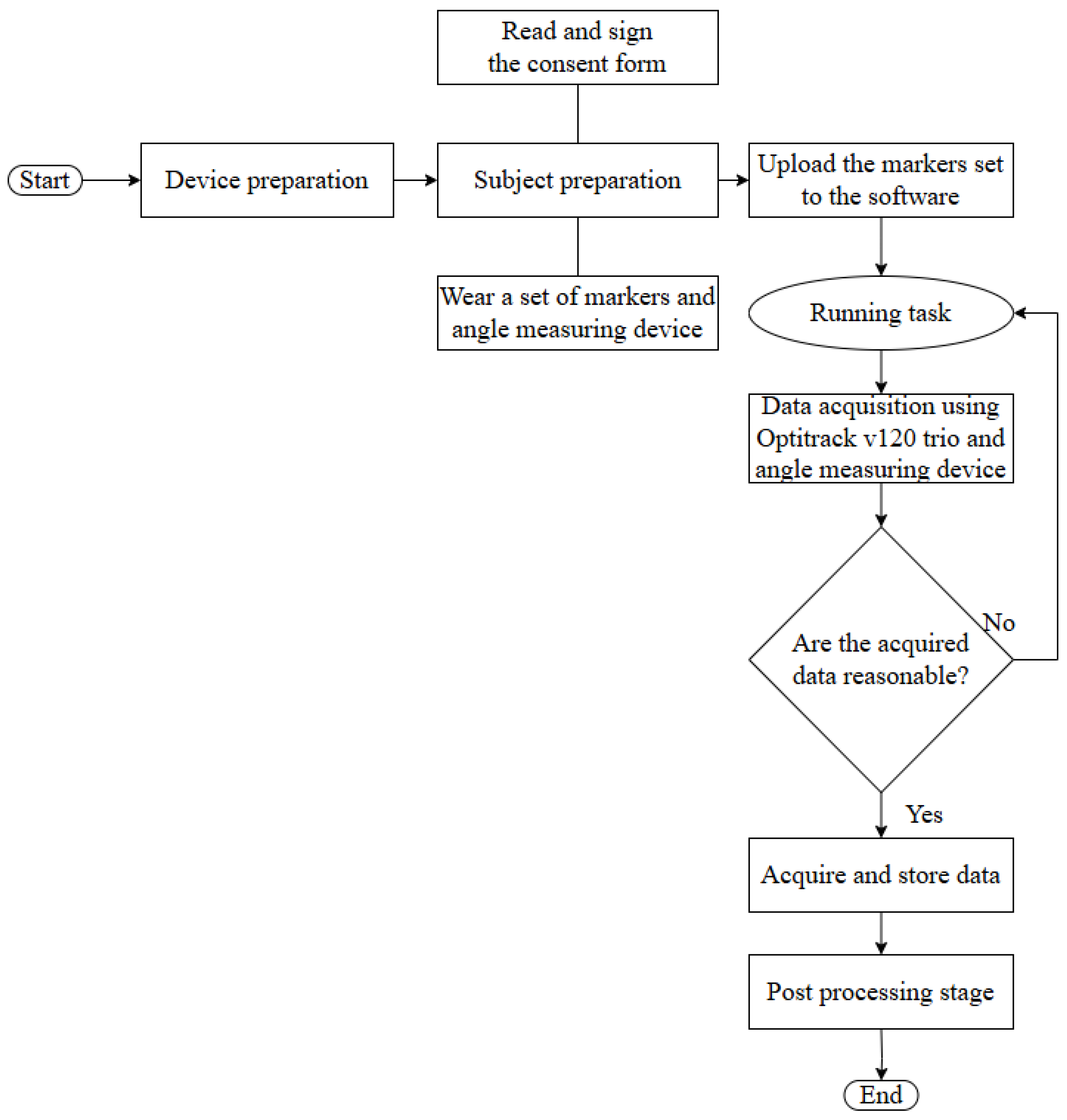
Figure 4 shows the flowchart of the proposed procedure for data collection: Step 1 corresponds to preparing the devices, MoCap and AMD for data acquisition. Step 2 involves subject preparation, including reading and signing the informed consent form and wearing the markers set and AMD. Step 3 involves uploading the markers set into the software. Step 4 initiates the task. Step 5 captures the positions of the markers and IMU from AMD during the execution of the movement. Step 6 verifies the accuracy of the acquisition. The process is then repeated for all tasks, first for the right foot and then for the left. Step 7 involves post-processing the data. Finally, Step 8 comprises saving and storing data on a computer.
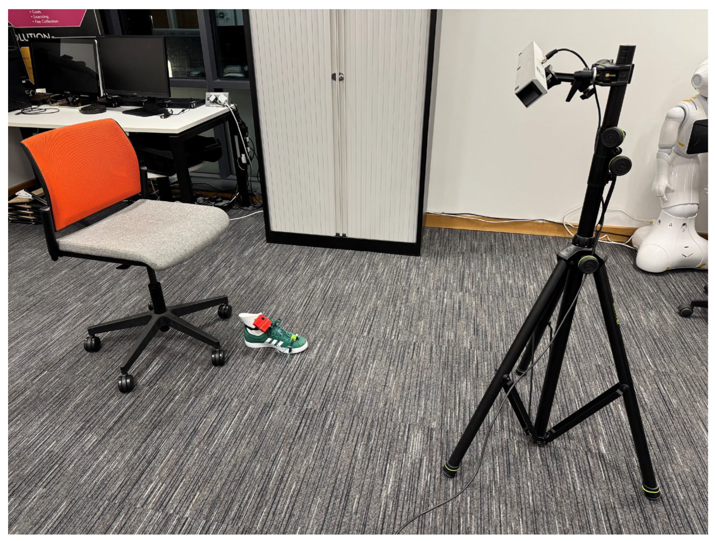
Figure 5 shows the experiment layout with a chair on which the participant is seated to perform the tasks in a sitting position. A foot mannequin with the AMD attached is present. In front of the participant, the MoCap camera system is positioned. The participant is shown, via video, the foot movements to be performed. Before each trial, the correct positioning of the markers and the AMD was visually inspected to ensure consistency across acquisitions. The experimental environment was kept constant for all participants to minimise external sources of variability. Verbal instructions were provided to clarify the task execution when necessary. The entire protocol was conducted under the supervision of a trained operator to ensure compliance with the experimental procedure.
The AMD provides time-stamped measurements of angular velocity and linear acceleration along three orthogonal axes. From these signals, pitch, roll, and yaw angles are estimated through sensor fusion techniques, with the IMU positioned on the foot.
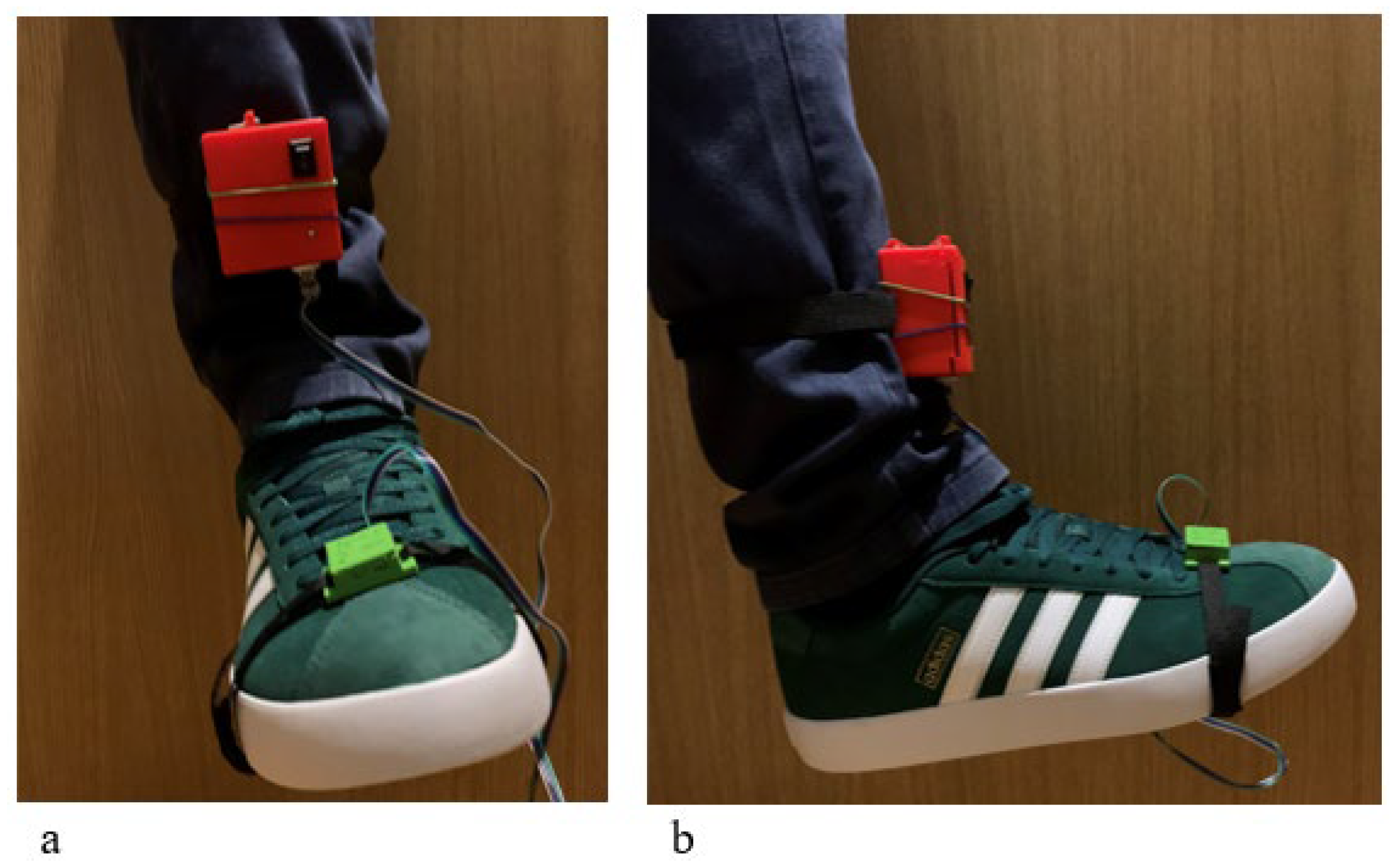
To perform the movements of plantarflexion/dorsiflexion, eversion/inversion and abduction/adduction the IMU sensor inside the little box was placed on the apical part of the foot. The biggest box is placed on the shin as can be seen in
Figure 6.
This modular and non-invasive sensing approach makes the proposed device suitable not only for ankle motion assessment but also for broader applications involving wearable robotics, assistive technologies, and rehabilitation systems requiring reliable kinematic monitoring.
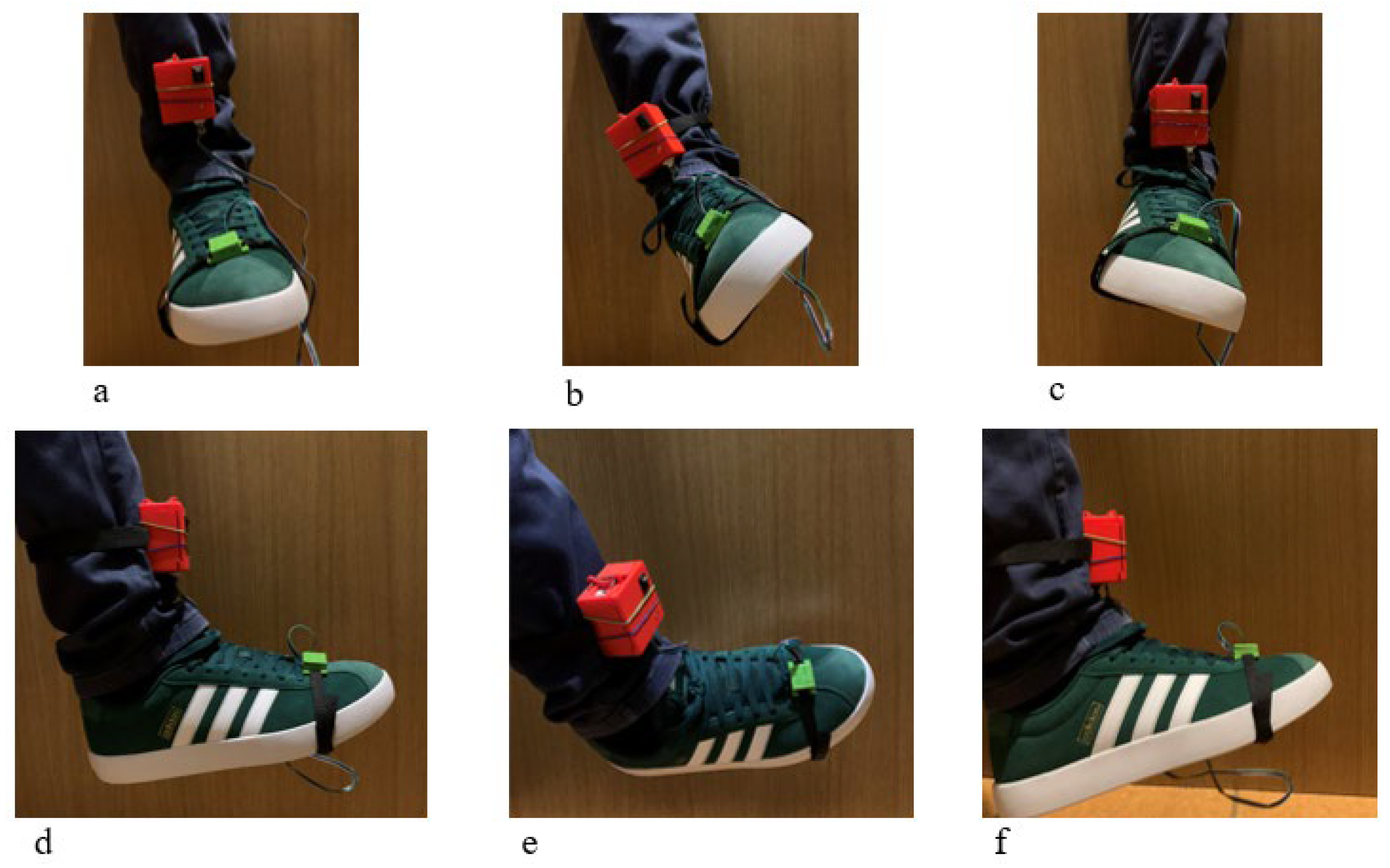
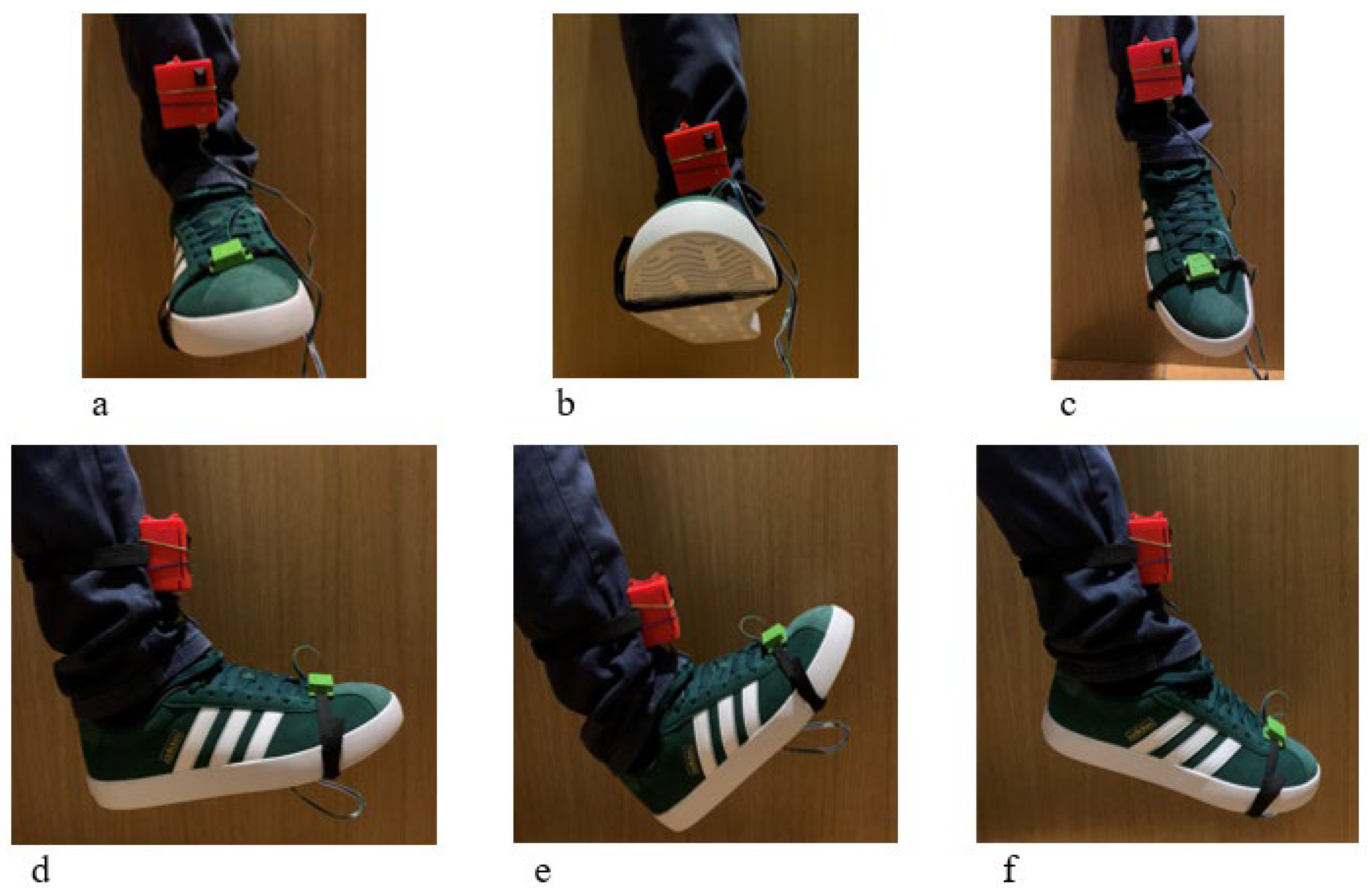
In
Figure 7 a snapshot of a test is shown from both frontal and lateral perspectives. The plantarflexion and dorsiflexion movements are made by the foot in the sagittal plane. Starting from the neutral position (
Figure 7a,d), maximum dorsiflexion is achieved by raising the tip of the foot as high as possible (
Figure 7b,e), while maximum plantarflexion is achieved by lowering the tip of the foot as far as possible (
Figure 7c,f).
In
Figure 8 a snapshot of the test is shown from both frontal and lateral perspectives. The eversion and inversion movements are made by the foot in the frontal plane with respect to the anteroposterior axis. Starting from the neutral position (
Figure 8a,d), maximum inversion is achieved by rotating the foot toward the medial side of the thigh until the maximum position is reached (
Figure 8b,e), while maximum eversion is achieved by rotating the foot toward the lateral side of the thigh (
Figure 8c,f).
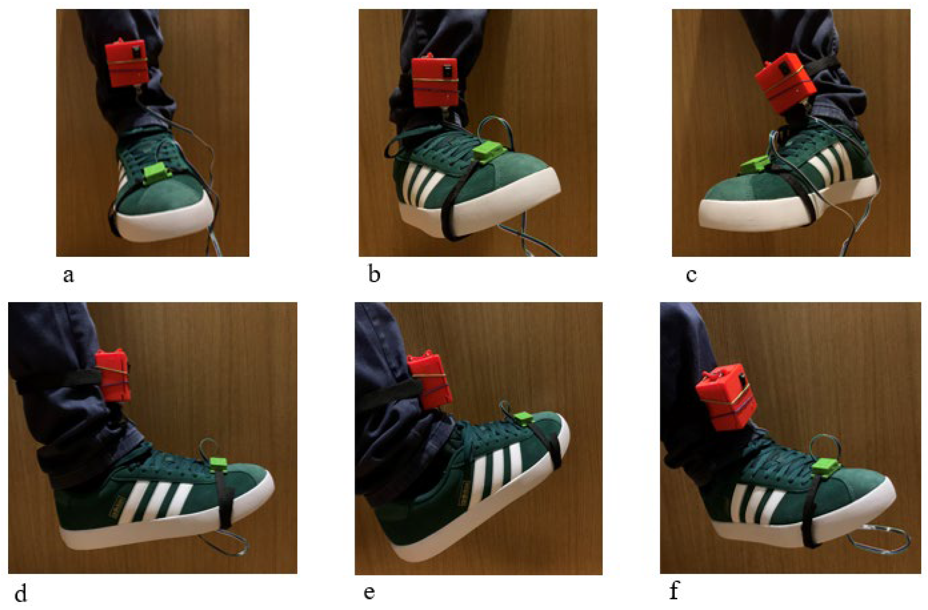
In
Figure 9 a snapshot of the test is shown from both frontal and lateral perspectives. The abduction and adduction movements are made by the foot in the transverse plane with respect to the vertical axis. Starting from the neutral position (
Figure 9a,d), maximum adduction is achieved by rotating the foot toward the medial side of the thigh (
Figure 9b,e), whereas maximum abduction is achieved by rotating the foot toward the lateral side of the thigh (
Figure 9c,f).
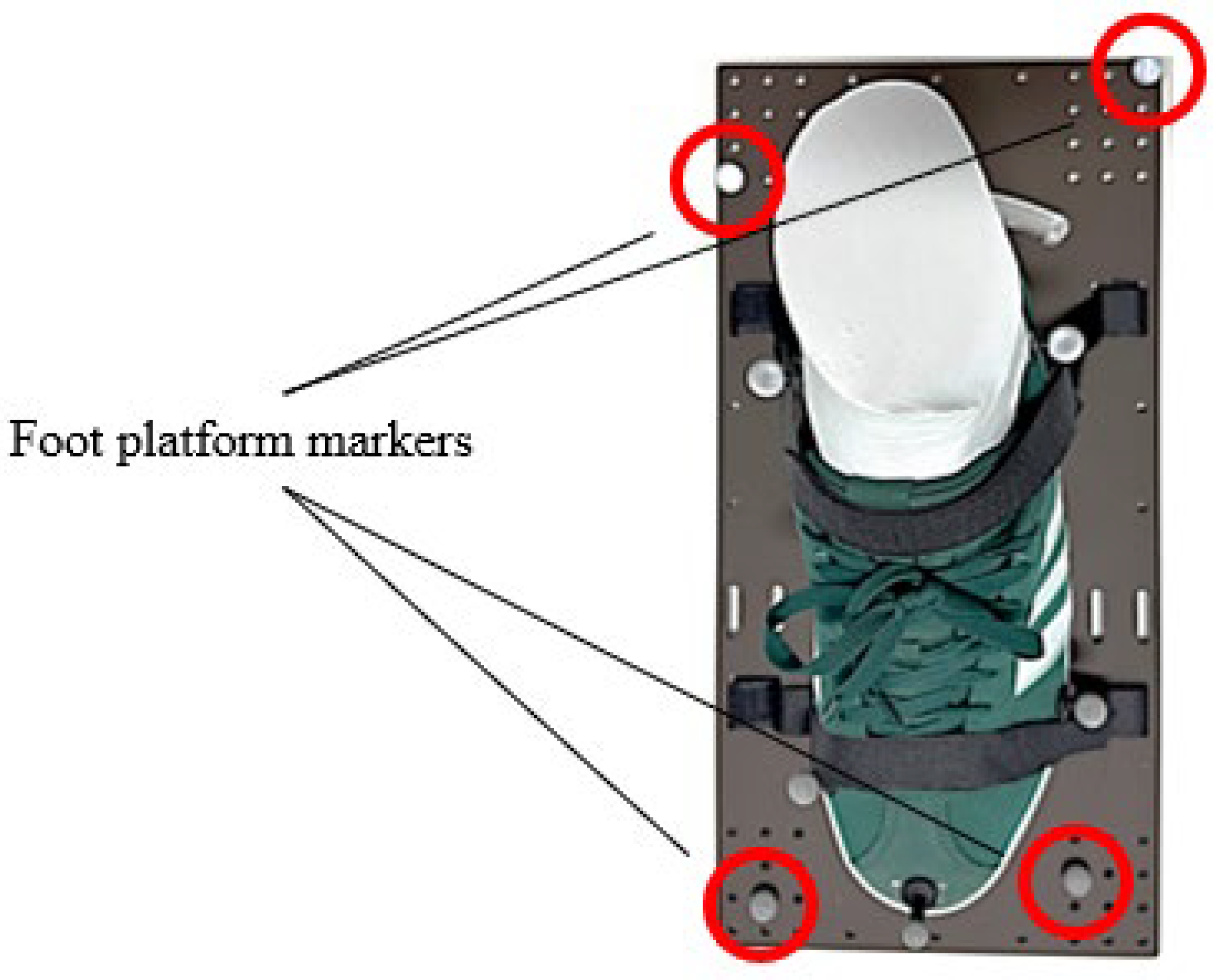
To perform the movements, a rectangular platform was placed beneath the participant’s foot. Five markers were positioned on the foot and four markers were positioned at the vertices of this platform in an asymmetric arrangement in order to facilitate robust tracking by the motion capture system. From the motion capture data of the markers on the foot platform, a representative frame will be extracted for comparison with the measurements obtained from the AMD. This setup ensures reliable tracking even if one of the markers is temporarily occluded, while the platform movement directly follows the participant’s foot, which naturally varies across subjects.
Figure 10 shows the marker setup: the markers highlighted in red were selected for the frame used to compute the rotational angles through the motion capture system.
To ensure correspondence between the sensor reference frame and the anatomical joint motions, IMU sensors were positioned on the dorsal aspect of the foot, near the toes, aligning the sensor with the distal segment of the ankle joint, as shown in
Figure 6. Participants were then instructed to perform controlled ankle movements corresponding to the primary anatomical degrees of freedom (plantarflexion/dorsiflexion, inversion/eversion, and abduction/adduction) while seated to minimise compensatory lower limb motions. The IMU-derived orientation estimates were directly compared with anatomically referenced joint angles obtained from the optical motion capture system, allowing verification that the measured signals corresponded to the expected anatomical motion components.
After acquisition, the experimental data were processed following a post-processing pipeline that is specifically designed to enable a reliable comparison between the AMD and MoCap reference system. All analyses were conducted in MATLAB R2025b, where signal conditioning, sensor fusion, and quantitative error metrics were implemented.
Since the MoCap system and the AMD operate with independent acquisition hardware and different sampling frequencies, temporal synchronisation was performed through a software-based alignment procedure. The temporal delay between the two signals was estimated using cross-correlation, which identifies the time shift that maximises the similarity between the signals.
Following synchronisation, both datasets were normalised to a common dimensionless time scale ranging from 0 to 100% of the movement cycle. This normalisation was applied independently to each dataset to account for small variations in trial duration.
Finally, both synchronised signals were resampled using linear interpolation to obtain 1000 equally spaced samples over the normalised movement cycle. This procedure ensures that the two signals share the same temporal resolution and allows a consistent point-by-point comparison between the AMD and MoCap measurements, enabling the reliable computation of similarity metrics such as RMSE and cosine similarity.
Accurate estimation of ankle orientation is essential for biomechanical analysis and rehabilitation applications. To this end, orientation was computed by fusing inertial measurements acquired from the wearable device, namely triaxial accelerometer and gyroscope signals. Raw inertial data are inherently affected by sensor noise, bias, and external disturbances; therefore, appropriate filtering and sensor fusion techniques were applied to enhance signal quality and ensure stable orientation estimates.
High-frequency noise was attenuated using a second-order Butterworth low-pass filter with a cutoff frequency of 5 Hz, applied to both accelerometer and gyroscope signals. The cut-off frequency of the low-pass filter was selected based on typical frequency characteristics of human joint kinematics reported in the biomechanical literature [
63], where most voluntary limb movements occur within a bandwidth below approximately 5–6 Hz. Such filtering strategies are commonly adopted in human motion analysis to attenuate high-frequency sensor noise while preserving physiologically relevant motion components. Initial estimates of ankle orientation were obtained from accelerometer measurements using trigonometric relations:
However, due to the sensitivity of accelerometers to transient accelerations, these estimates were used only as initial conditions for subsequent sensor fusion.
To overcome the complementary limitations of inertial sensors, namely gyroscope drift and accelerometer noise, a Kalman filter [
64,
65,
66] was employed to fuse angular velocity and acceleration data. The estimation process consists of a prediction step, in which angular velocity measurements are integrated to propagate orientation states, and an update step, in which accelerometer-derived orientation information is used to correct drift and improve long-term accuracy.
For the estimation process, the Kalman filter can be expressed using a discrete-time state-space formulation. The state vector
xk at
k time represents the ankle orientation expressed through the roll and pitch angles as
The prediction step propagates the orientation state using angular velocity measurements from the gyroscope. The system dynamics are expressed as
where
Ts is the sampling period,
ωx and
ωy are the gyroscope angular velocity measurements, and
ωk represents the process noise accounting for modelling uncertainties and gyroscope integration errors. This formulation corresponds to the strapdown inertial integration of angular velocity measurements. Accelerometer measurements provide indirect information about orientation through the gravity vector. Roll and pitch angles can be derived from accelerometer measurements and are used as observations:
The measurement model is therefore
where
and
nk represents measurement noise associated with accelerometer uncertainties.
Roll and pitch can be computed through alignment with the gravity vector measured by the accelerometer. Conversely, yaw cannot be directly estimated from accelerometer measurements because gravity does not contain heading information. For this reason, yaw is primarily obtained by integrating the gyroscope angular velocity and applying additional drift mitigation strategies [
67].
Angular orientation (roll, pitch, and yaw) was initially obtained by integrating the gyroscope signals over time using
While this approach provides accurate short-term tracking of dynamic movements, it introduces cumulative drift that degrades long-term accuracy if left uncorrected. The Kalman filter mitigates this effect by optimally combining the high-frequency responsiveness of the gyroscope with the low-frequency stability of the accelerometer.
The process noise covariance matrix accounts for uncertainties in the system model, primarily related to gyroscope integration errors. Small process noise values were introduced to allow gradual correction of accumulated drift without compromising stability as
where
and
are small variance values representing model uncertainty. A higher
Q value makes the system trust the gyroscope less, while a lower
Q keeps predictions stable but less adaptive. The following values were adopted for the computational procedure:
= 0.001° and
.
The measurement noise covariance represents sensor inaccuracies, mainly from the accelerometer. Since accelerometer readings can be affected by external accelerations, a Kalman filter assigns a higher noise value to prevent overcorrection in terms of
where
and
define the uncertainty in accelerometer-derived angles. A higher
R reduces reliance on the accelerometer (useful in dynamic motion), while a lower
R prioritises accelerometer stability. The following values were adopted for the computational procedure:
= 0.03° and
after preliminary test.
At each time step the Kalman filter predicts the new angles using gyroscope integration, computes the error covariance matrix by updating
P, state uncertainty, as
and computes the Kalman Gain
K, which determines how much to correct the estimate using
and updates the estimated angles by incorporating accelerometer corrections given by
and updates the covariance matrix to reflect the new uncertainty
This adaptive process dynamically balances the relative confidence that is assigned to gyroscope and accelerometer measurements depending on motion conditions.
Unlike roll and pitch, yaw cannot be directly estimated from the accelerometer, as gravity does not affect rotation around the vertical axis. Consequently, yaw estimation relies entirely on gyroscope integration, which is susceptible to drift. To mitigate this limitation, an additional Kalman filter step is applied. A pseudo-measurement of yaw is obtained from the accelerometer using
The Kalman filter update is performed similarly to roll and pitch, using a different covariance matrix for yaw. The following values were adopted for the computational procedure,
= 0.01° and
, to give
Additionally, yaw estimates were periodically reset every 10 s to prevent unbounded drift over prolonged acquisition periods. This strategy is particularly suitable for rehabilitation and motion monitoring applications, where relative orientation changes are of primary interest. This limitation reflects a fundamental property of inertial sensing, as rotation around the vertical axis cannot be directly observed from gravitational acceleration alone. Consequently, yaw estimation relies primarily on gyroscope integration combined with drift mitigation strategies, which remain suitable for short-duration movement monitoring tasks typical of rehabilitation exercises. Within this context, the proposed formulation provides a stable and sufficiently accurate estimation of the relative yaw variations required for the targeted rehabilitation monitoring tasks.
The effectiveness of the proposed inertial sensing approach was evaluated by comparison with an optical motion capture system (OptiTrack V120 Trio), which served as a laboratory-grade reference. The MoCap system operates at a sampling frequency of 120 Hz and employs three infrared cameras in conjunction with Motive: Tracker 2.3.6 software [
68] to accurately reconstruct three-dimensional marker trajectories.
Prior to each recording session, the motion capture system was calibrated to ensure accurate spatial reconstruction. Since the OptiTrack V120 Trio consists of a rigid block of cameras with fixed relative geometry, the calibration procedure is simplified and does not require individual camera alignment. Calibration was performed using the calibration probe that is provided by the manufacturer [
69]. During this procedure, the probe containing reflective markers is placed on the ground plane of the capture volume. The software automatically detects the probe markers and identifies the ground plane, which is subsequently defined as the global reference plane of the measurement environment.
Following system calibration, a rigid body model was created to track the motion of the monitored object. A rigid body requires a minimum of three reflective markers placed on the object to be tracked. These markers must remain visible within the field of view of at least one camera during acquisition. Once defined in the Motive software (Version 2.3.6 Final), the rigid body is assigned a pivot point corresponding to the geometric centre of the marker configuration. By default, the orientation axes of the rigid body are aligned with the global coordinate system defined during calibration. This rigid body definition allows the system to compute both the position and orientation of the tracked object throughout the recording.
After data acquisition, MoCap recordings underwent standard post-processing, including manual relabelling of markers not automatically identified by the software and gap filling to reconstruct short occlusions. Once processing was completed, the three-dimensional Cartesian coordinates of each marker were exported in CSV format for subsequent kinematic analysis and comparison with wearable sensor data.
For each marker, the corresponding Cartesian coordinates were identified as
where
xi (
t),
yi (
t), and
zi (
t) represent the time-varying spatial coordinates of the marker in the global MoCap reference frame.
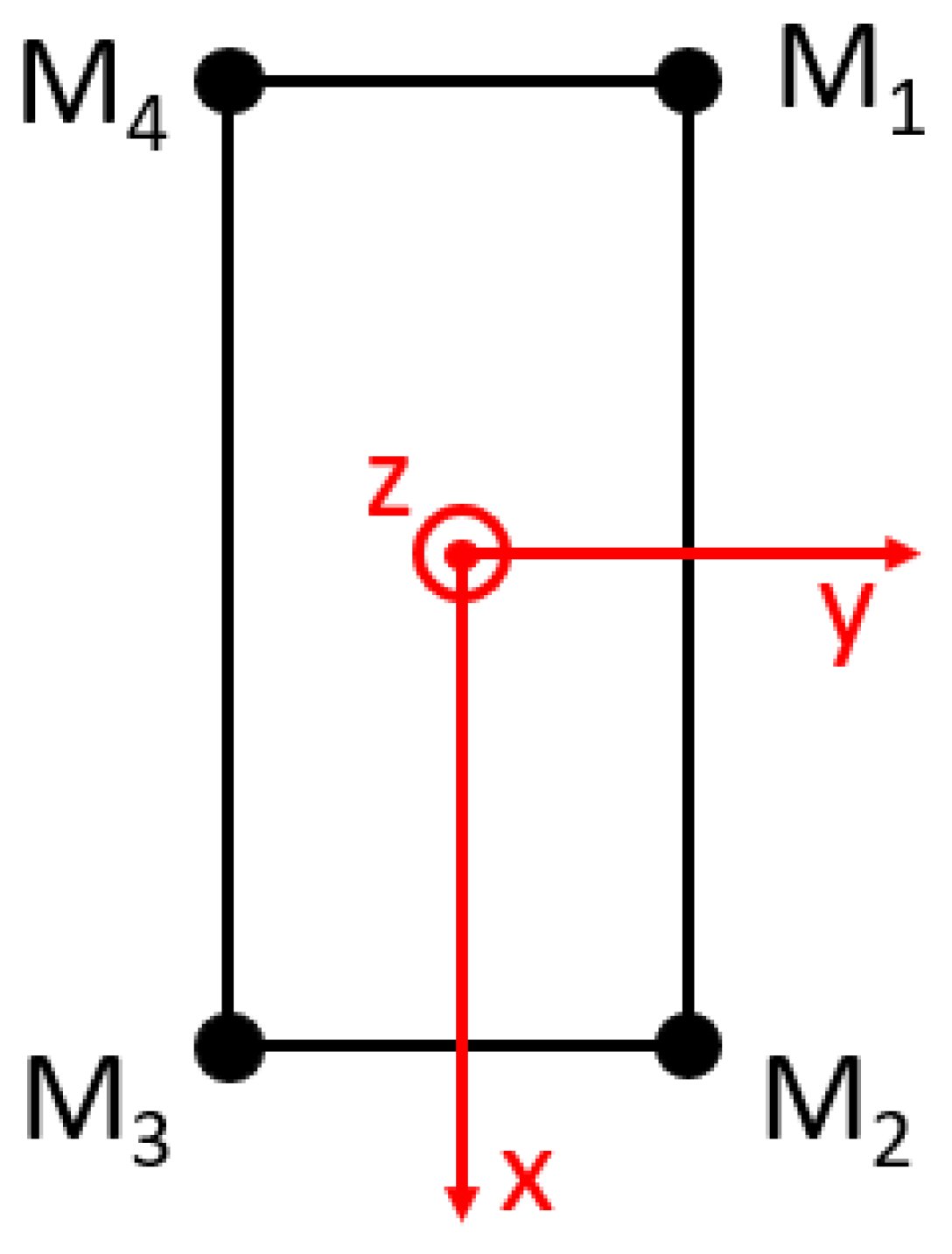
A subset of four markers defining the foot platform was selected from the dataset, as shown in
Figure 10.
Figure 11 shows the foot platform reference system with markers M1 to M4.
Let the marker positions be denoted as
M1(
t),
M2(
t),
M3(
t),
M4(
t). The segment reference point
M(
t), representing the geometric centre of the foot platform, was computed as
This point was used as the origin of the local segment coordinate system.
A right-handed orthonormal coordinate system was constructed for the foot platform using marker geometry.
The preliminary longitudinal axis was defined as
and it was normalised to obtain the unit vector
Similarly, a temporary mediolateral direction was computed as
To ensure orthogonality with
XM, a Gram–Schmidt orthogonalization was applied:
The third axis was obtained via the following cross product:
This procedure ensured a mutually orthogonal and normalised anatomical reference frame.
For each time frame, the segment orientation was represented by a rotation matrix:
Euler angles were extracted from the rotation matrix using a fixed rotation sequence. The pitch, roll, and yaw angles were computed as
where arctan2 ( · , · ) denotes the four-quadrant inverse tangent function.
Due to differences in acquisition duration and sampling between the two systems, both signals were temporally normalised onto a common dimensionless time scale ranging from 0 to 100 of the movement cycle.
For each signal, time normalisation was performed as follows:
This normalisation enabled direct point-wise comparison across the entire dorsiflexion–plantarflexion cycle, independently of absolute trial duration.
Following normalisation, the AMD signal was interpolated onto the MoCap time base using linear interpolation:
This step ensured equal vector length and point-to-point correspondence between AMD and MoCap signals, which is required for quantitative error analysis.
To assess waveform similarity independently of amplitude scaling, cosine similarity was computed [
70]:
where the MoCap and AMD represent angle vectors, respectively.
Cosine similarity values close to 1 indicate strong agreement in signal shape and temporal evolution, even in the presence of systematic offsets.
The absolute agreement between the two systems was quantified using the Root Mean Square Error (RMSE) [
70]:
RMSE provides a measure of the average magnitude of angular discrepancy throughout the movement cycle.
To express the error relative to the movement amplitude, RMSE was normalised using the maximum range of variation between the two signals [
70]:
This percentage-based metric facilitates comparison with values reported in the literature.
The absolute error between AMD and MoCap signals was computed pointwise as follows:
This analysis enabled identification of movement phases associated with increased estimation error, such as transition regions between movements.
4. Discussion
Unlike many IMU-based studies that primarily focus on algorithmic accuracy under controlled laboratory conditions, the present work frames the sensing module as a deployable kinematic measurement unit designed for integration within wearable rehabilitation or assistive robotic systems. The proposed architecture emphasises practical deployability by combining a low-cost hardware platform of about 50 €, magnetometer-free orientation estimation with bounded yaw drift, and full-plane validation against an optical motion capture reference system.
In addition, the angle measuring device (AMD) is conceived as a stand-alone wearable sensor module, capable of operating independently from external computing devices. The system can be activated simply by pressing the power button, and all measurements are locally stored on an SD card, ensuring that data remain accessible even without wireless connectivity or external hardware. This design makes the device particularly suitable for rehabilitation scenarios involving elderly users or home-based monitoring applications, where ease of use and technological accessibility are essential.
It should be noted that the experimental protocol was intentionally conducted under controlled laboratory conditions with seated ankle movements in order to isolate joint kinematics and ensure a reliable comparison between the wearable sensing device and the optical motion capture reference system.
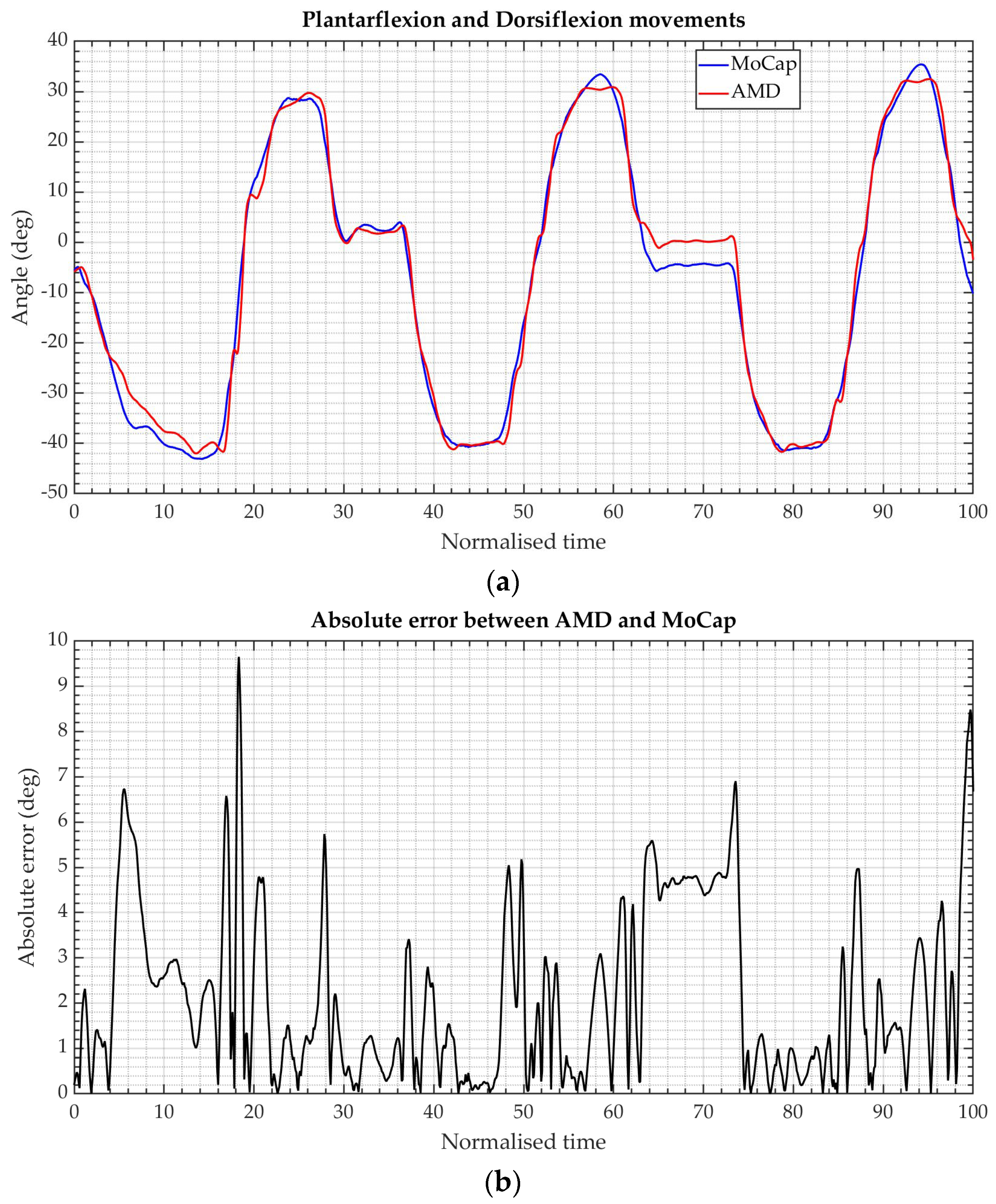
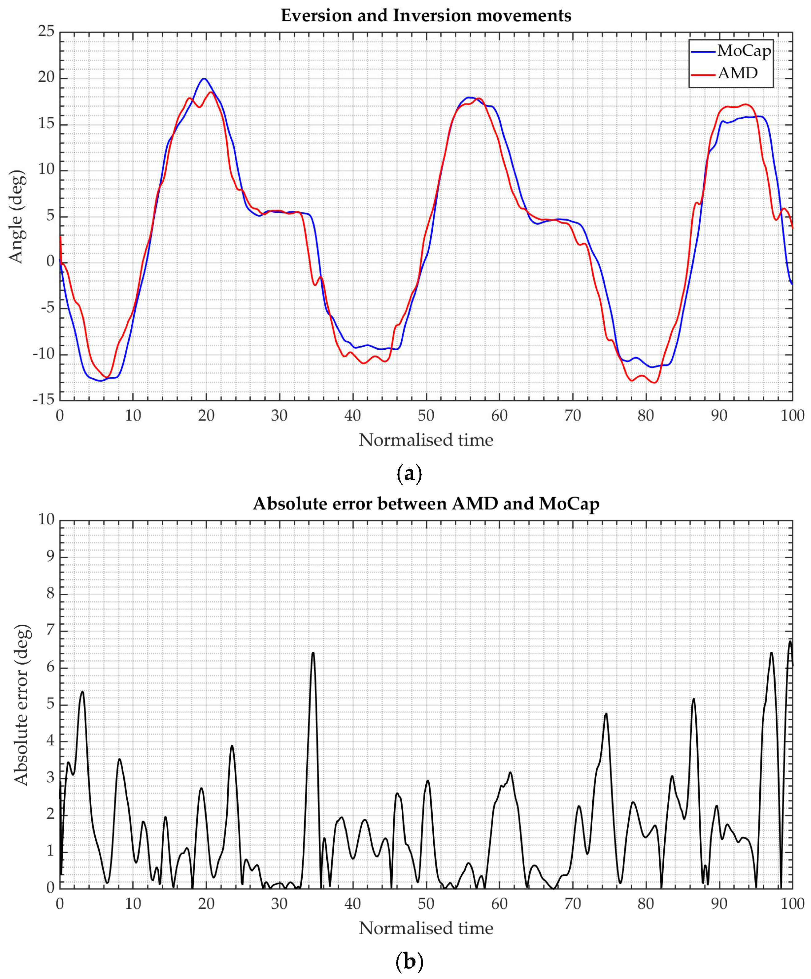
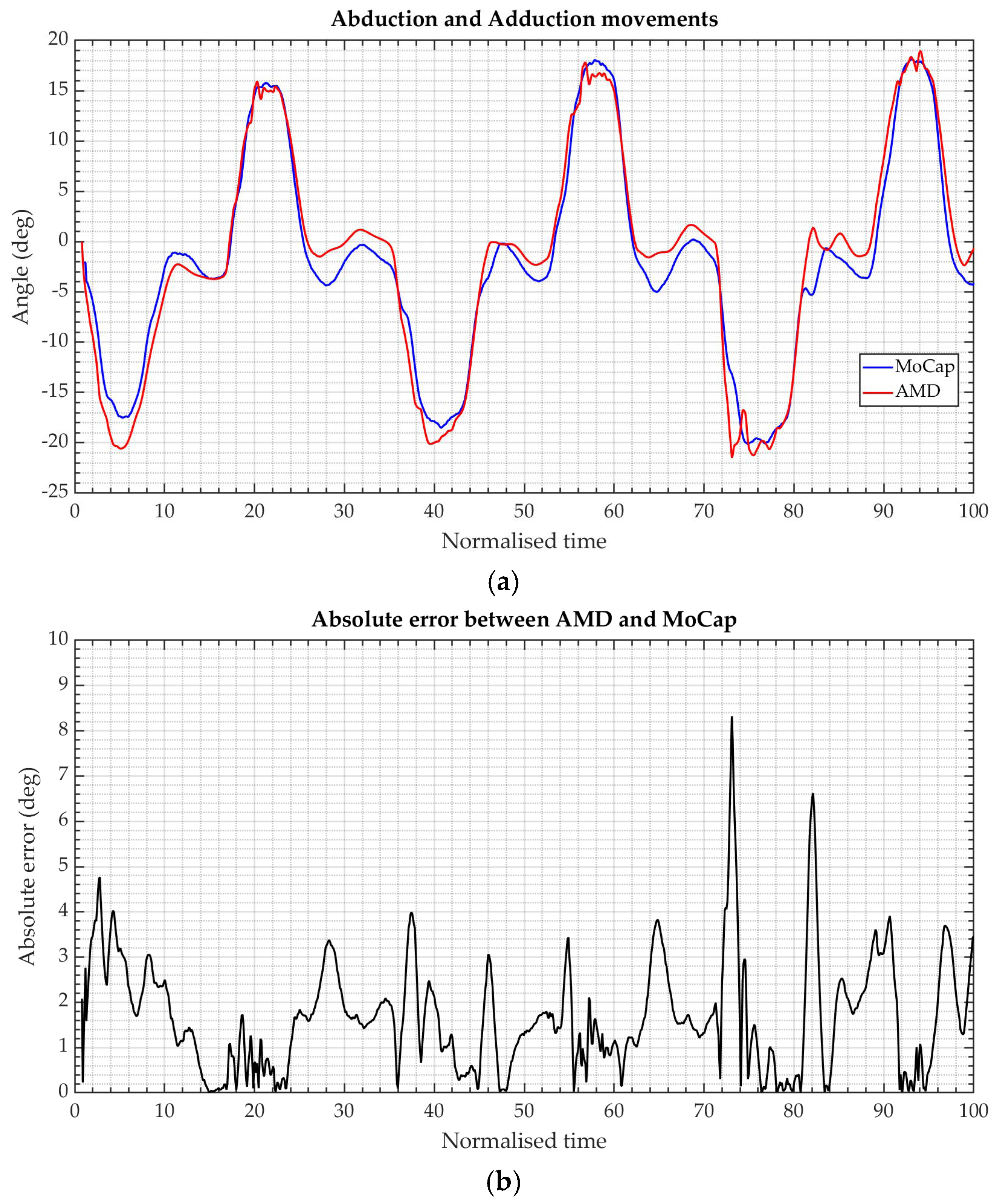
The experimental results demonstrate a strong agreement between the proposed wearable IMU-based angle measuring device and the optical motion capture reference across all tested ankle movements and anatomical planes. Time-normalised angular trajectories show that the wearable system accurately captures the shape, timing, and amplitude of joint motion for plantarflexion and dorsiflexion, eversion and inversion, and abduction and adduction, for both right and left feet.
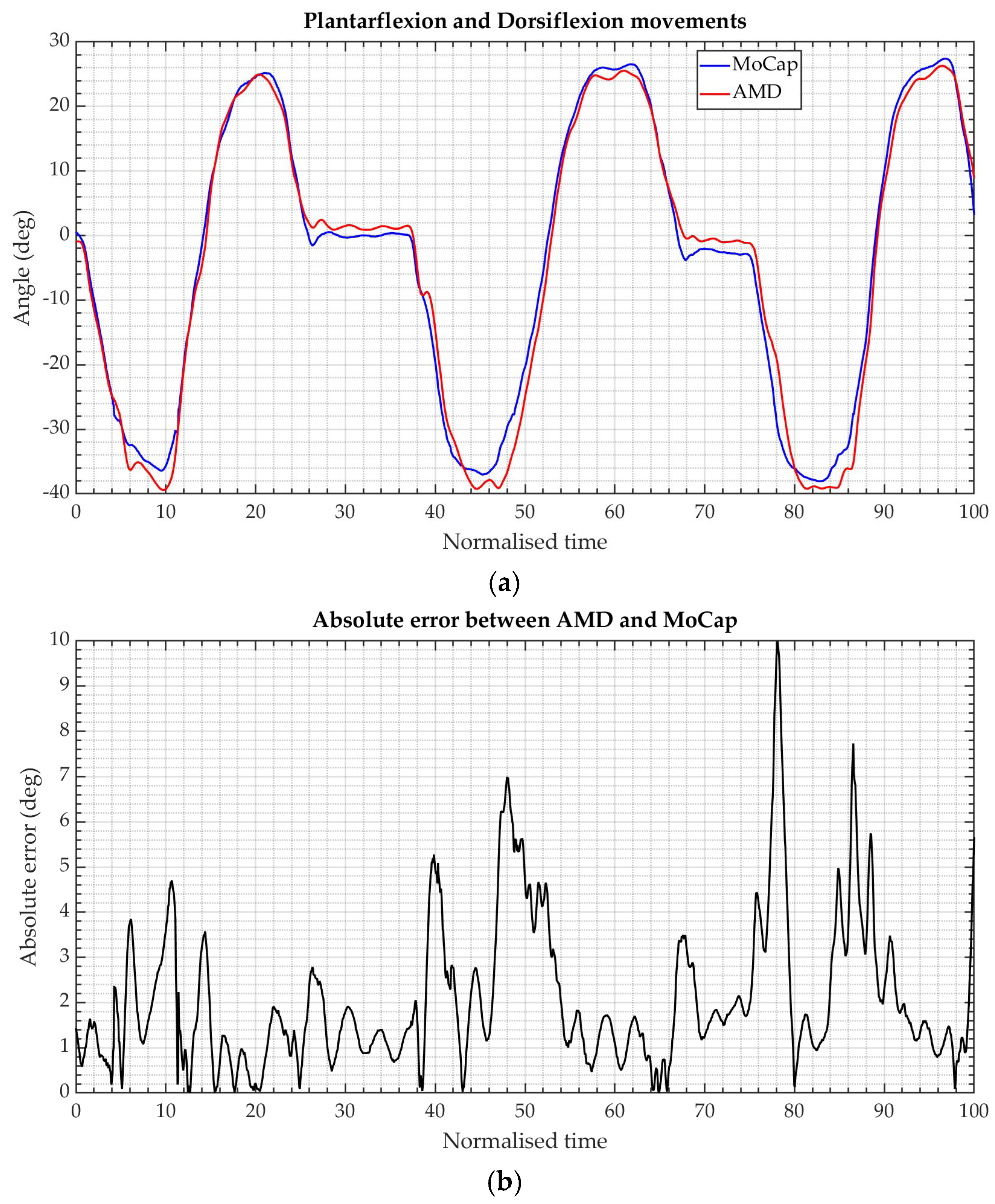
Plantarflexion and dorsiflexion were the most accurately tracked motion component: 0.99 cosine similarity, 3.8° RMSE, and 5.6% RMSE as a percentage. This result is expected, as it exhibits the largest range of motion and benefits from strong gravitational observability, which enhances pitch estimation through accelerometer correction. Accurate tracking in this plane is particularly relevant for gait analysis, balance assessment, and rehabilitation monitoring, where sagittal plane ankle motion plays a dominant functional role. These results indicate excellent waveform similarity and limited absolute deviation throughout the movement cycle.
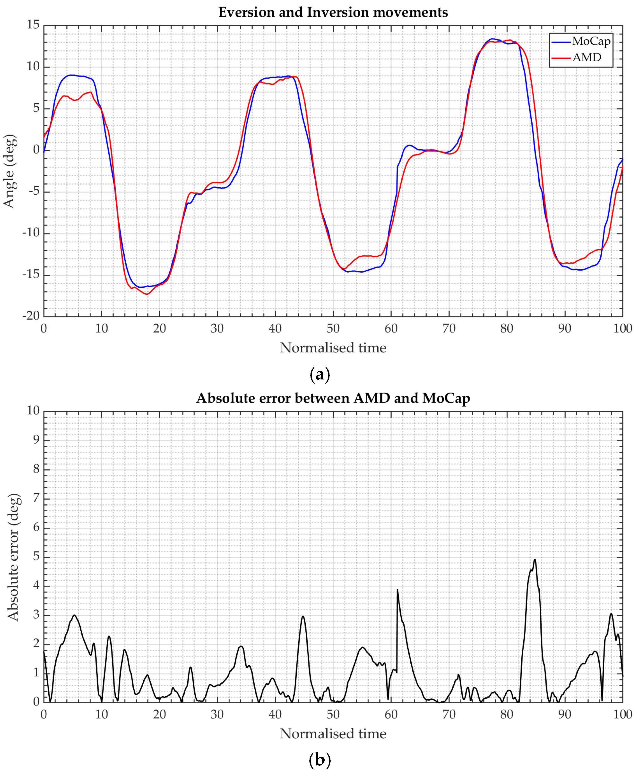
Eversion and inversion show an accuracy comparable to that of plantarflexion and dorsiflexion. Cosine similarity values remain consistently high, typically between 0.98 and 0.99, while RMSE values are slightly smaller than 0.3° in absolute terms. Although the normalised RMSE is slightly higher than around 0.7%, this effect is mainly attributable to the reduced range of motion involved rather than to a degradation in waveform tracking accuracy. Overall, the wearable system reliably captures frontal plane ankle kinematics with a performance comparable to sagittal plane movements.
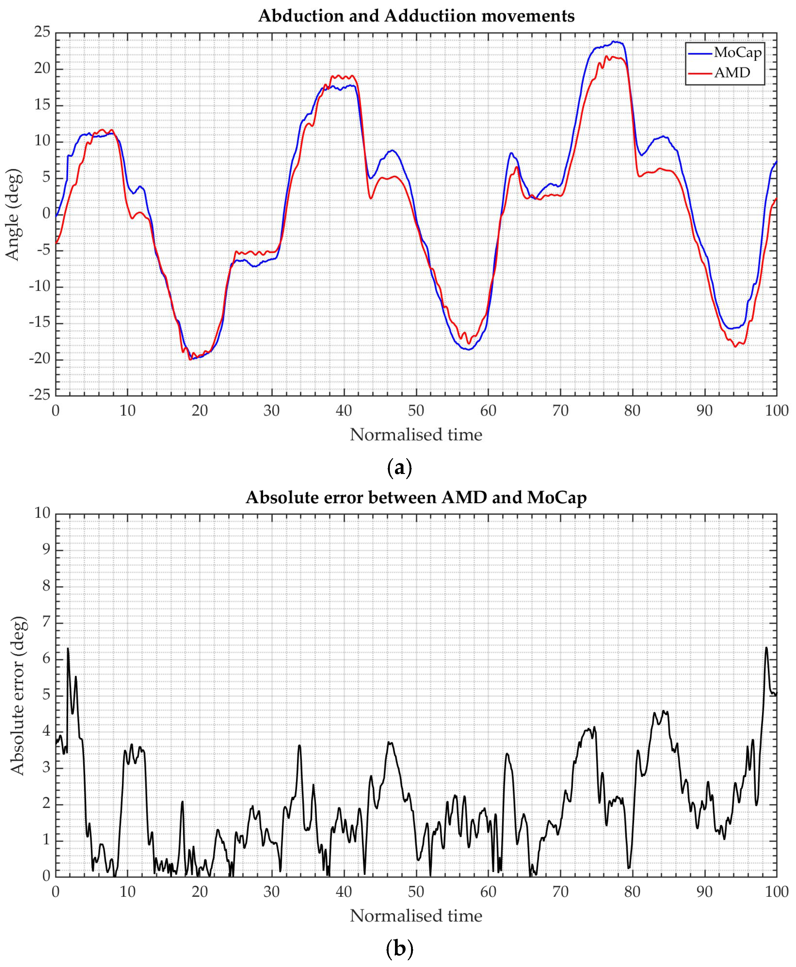
In contrast, abduction and adduction exhibit a lower accuracy compared to the other movement components. These results are less accurate than those obtained for plantarflexion and dorsiflexion, and eversion and inversion, likely due to the lack of a gravity-based correction for the vertical axis. While cosine similarity values remain above 0.97, both RMSE and normalised RMSE increase, 4.1° and 8.2% respectively, and a larger standard deviation is observed across subjects. This behaviour is primarily associated with yaw estimation, which lacks direct gravity-based correction and is therefore more sensitive to drift, sensor noise, and inter-subject variability. Despite these limitations, the system is still able to reproduce the general temporal pattern of transverse plane ankle motion, although with reduced quantitative accuracy compared to plantarflexion/dorsiflexion and eversion/inversion.
Nevertheless, the wearable system successfully captures the overall waveform shape and timing of these movements, confirming the reliable estimation of transverse plane ankle kinematics.
Although the absolute error between the AMD and MoCap waveforms occasionally reaches values of approximately 10°, this discrepancy is mainly attributable to a phase shift, i.e., a slight misalignment between the two signals, rather than to actual differences in that magnitude in joint angle estimation. Indeed, when analysing the waveforms at their characteristic points, such as maxima and minima, the two signals appear highly similar. In particular, the difference between AMD and MoCap is typically limited to approximately 2–3°, indicating that the wearable system accurately reproduces the true movement amplitude, while the observed larger pointwise errors are primarily driven by temporal misalignment effects. It should also be noted that time-normalising the signals to a 0–100% movement cycle, although commonly adopted for biomechanical waveform comparison, may partially mask small phase errors when the cycles are implicitly aligned. Consequently, some instantaneous deviations observed in the error plots are attributable to minor timing or phase misalignments between the AMD and MoCap signals, rather than to substantial differences in estimated joint angles. Importantly, this shift does not compromise the qualitative interpretation of movement patterns or the quantitative assessment of joint kinematics.
These findings indicate that the wearable system is capable of accurately reproducing both the temporal evolution and the amplitude of ankle joint kinematics, with errors remaining within clinically acceptable limits across all degrees of freedom. Overall, the summary results reported in
Table 6 confirm a strong agreement between the proposed angle measuring device and the optical motion capture system across all tested movements.
From a methodological perspective, the comparison highlights the complementary nature of the two measurement paradigms. Optical motion capture reconstructs segment orientation deterministically from marker geometry and spatial relationships, resulting in drift-free and highly stable measurements under controlled laboratory conditions. In contrast, the AMD approach estimates orientation through numerical integration and probabilistic sensor fusion, enabling portability and real-world applicability at the expense of increased sensitivity to sensor noise and drift.
Yaw estimation remains the most critical aspect of inertial sensing, as it is weakly observable without an absolute heading reference. As expected from inertial navigation theory, yaw is more susceptible to drift than roll and pitch. However, within the duration and characteristics of the performed tasks, the implemented drift mitigation strategy ensures bounded error and preserves the reliable estimation of relative rotational dynamics.
Statistical aggregation across all subjects confirms good repeatability and limited inter subject variability. No systematic differences are observed between left and right ankles, supporting the robustness of the sensing approach across different anatomical configurations.
Overall, the high cosine similarity values and the limited absolute and relative errors demonstrate that the proposed system achieves a favourable balance between accuracy, cost, usability, and integration potential, making it well suited for wearable robotics, assistive devices, and home-based rehabilitation systems. In practical applications, additional sources of variability may arise from factors such as sensor placement variability, strap tightness, and soft tissue motion artefacts. While these aspects were minimised during the controlled experimental campaign, their influence will be investigated in future studies involving functional movements and real-world monitoring scenarios.




 ,
,