1. Introduction
Robotics education at the undergraduate level is at a crossroads in terms of educators’ understanding of how to teach these future practitioners. Industrial demand for robotics engineers continues to grow in spaces such as general automation, autonomous vehicles, agriculture, and manufacturing, among many others. However, teaching robotics effectively requires students to explore multiple disciplines, including controls, embedded systems, sensors and signal processing, algorithms, and artificial intelligence. This multi-disciplinary nature makes it challenging to provide comprehensive robotics education within the constraints of a traditional undergraduate curriculum.
Engineering undergraduate degrees tend to emerge based on growing industrial needs. This progression can be seen historically when electrical engineering undergraduates emerged from the need for applied physicists and mathematicians in the broad field of electromagnetic spectrum harnessing for various applications in the 1960s and 1970s. Similarly, computer engineering emerged in the 1980s and 1990s as the emergence of large computer manufacturing companies needed individuals focused on this. Now, in the 2010s and 2020s, we see a need for engineers with a skill set in robotics engineering. Here, we define a robotics engineer as an engineer who applies an understanding of harnessing sensing, making computational control decisions, and responding with actuation in the real world via the design and refinement of automated systems/machines.
Miami University has recently responded to industrial needs with robotics engineering, and we have begun exploring students’ project-based learning in robotics education through capstone design projects and dedicated robotics laboratory courses. Our focus has been on using low-cost, first-principles robots that expose students to fundamental concepts in embedded systems, sensors, and actuators. This approach aligns with similar efforts at other institutions to provide hands-on robotics experience using accessible platforms.
Borrowing the approach from the Open Systems Interconnection (OSI) layered model in computer networking [
1], we propose a similar approach to understanding robotics systems in relation to system levels and education.
Figure 1 shows our proposed seven-layer model for robotics engineering: the Robotic System Levels (RSL) model. This model provides a structured way to understand the different levels of abstraction in robotic systems, from hardware to high-level planning, starting from the bottom:
Level 1—Physical Layer: Comprises the mechanical structure, actuators, and sensors that make up the robot’s hardware. Hardware may include motors, encoders, cameras, and the physical chassis.
Level 2—Electrical Layer: The power systems, signal conditioning, and basic electrical interfaces enable communication between hardware components. Common ideas here are communication protocols, including networking concepts.
Level 3—Embedded Layer: Encompasses microcontrollers, real-time operating systems, and low-level firmware that directly interface with hardware. Many of the ideas here involve the low-level embedded system control at the microcontroller design level and what might be called the firmware or hardware/software codesign level.
Level 4—Control Layer: Implements feedback control systems and basic motion control algorithms now at higher levels, moving into a more software-defined space.
Level 5—Perception Layer: Processes sensor data to build an understanding of the robot’s environment, including object detection, localization, and mapping.
Level 6—Planning Layer: Handles path planning, task scheduling, and behavioral decision-making based on environmental perception.
Level 7—Mission Layer: Defines high-level goals, multi-robot coordination, and human-robot interaction protocols.
Each layer provides services to the layer above while abstracting implementation details. This separation of concerns allows roboticists to focus on specific aspects of the system while providing clear interfaces between components. For example, the Planning Layer can generate paths without understanding how the Control Layer will execute the required motions. First-principled robotic design, as we have defined it here, focuses on Level 1 and Level 2.
Our proposed Robotic System Levels model builds upon established educational approaches such as Project-Based Learning and Experiential Learning while also addressing specific challenges in robotics education. Specifically, traditional Project-Based Learning approaches in robotics emphasize student autonomy and focus primarily on final project outcomes. In contrast, the RSL model introduces a structured, hierarchical progression that advances from first principles to complex system integration and is designed to provide scaffolding for novice learners. While the Experiential Learning Model highlights learning through a cycle of experience and reflection, the RSL model formalizes this progression into clearly defined levels of robotic systems (e.g., sensing, actuation, control, and integration). This system-level structure enables instructors to more effectively guide students through the complexities of robotics in a coherent, component-wise manner.
Over three years, we have guided capstone teams through increasingly complex swarm robotics projects while developing and refining laboratory exercises for our “ECE 314: Elements of Robotics course”. These educational experiences center on “cheap first-principled robots”—simple platforms requiring students to work directly with microcontrollers and basic sensors/actuators rather than using more sophisticated commercial robotics platforms. This approach forces students to understand core embedded system concepts and principles but also presents specific challenges and trade-offs regarding learning outcomes.
The contributions of this work include the following:
A case study analysis of three years of swarm robotics capstone projects, examining how increasing project complexity impacts student learning outcomes.
An evaluation of laboratory modules developed for ECE 314 that utilize low-cost robotics platforms.
A critical assessment of the benefits and limitations of using these first-principle robot projects in undergraduate robotics education.
We propose the above RSL model. This model helps educators to understand the breadth of robotics and to determine how much time should be spent on various aspects of robotics.
This paper examines these experiences to evaluate the effectiveness of our approach and provide insights for other institutions developing undergraduate robotics programs. While we find value in having students work with first-principles robots, our results suggest that this should be balanced with exposure to modern robotics platforms and tools used in the industry. This, however, comes at the cost of having more expensive robotic kits that can be used to explore how to implement the application of robots at a higher level.
2. Robotic Education Background
In this section, we review research into education and project-based learning [
2,
3] to develop an understanding of what educators have explored for teaching robotics. Note that the education space is large, and we have focused on selecting a subset of research in this regard.
Before the idea of a focused undergraduate teaching students to use and build robots, the educational focus was on how to use robots to teach concepts in computer science and electrical engineering [
4,
5,
6]. The goals were on project-based learning and the creation of robots at
Level 1,
Level 2, and
Level 3 of our RSL model (
Figure 1). Robotics competitions were also popular undergraduate activities, and Miami University has a history of competing in robotic competitions [
7,
8]. As we will discuss later, much of this is due to the democratization of embedded system design [
9].
More recently, robotics education has shifted somewhat to how the technology can be used and taught as industry now requires more automated systems, and hands-on robotic opportunities allow students to apply theoretical concepts while developing critical thinking and problem-solving skills [
10]. Doschanov et al. [
11] propose integrating computational thinking with physical computing. These studies suggest that project-based learning and hands-on approaches remain central to effective robotics education. Robotics is a popular application space in a number of spaces [
12].
During COVID-19, significant changes in robotics education changed somewhat as in all other fields. Birk et al. [
13] examine the transition to online robotics courses, finding that simulation tools and remote lab access became essential for maintaining educational quality. Similarly, Maurelli et al. [
14] looked into curriculum needs during COVID-19. The most comprehensive recent look at robotics as a curriculum is by Shibata et al. [
15].
From the perspective of the impact of robot projects on early STEM learners, Rocker et al. [
16] studied graduates of the FIRST robotics program, demonstrating that participation correlates with increased interest in STEM careers and the development of teamwork abilities. These early experiences were examined more by Verner et al. [
17] for collaborative sensing projects in high school contexts. Robotic STEM experiences are widespread in North America as activities that sit at
Level 1 to
Level 4 within our RSL model and are used extensively to push students and recruit them into the technological education space.
In contrast, automation and robotics play a role in helping us teach and learn. Some recent examples include the role of social robots in education, which represents an emerging area [
18], and studies like Hoorn et al. [
19] demonstrate that robots can function as tutors. However, learning gains vary significantly between students. This highlights the need for careful integration of robotic systems into educational environments.
At the higher education level, robotics capstone courses provide culminating experiences integrating multiple engineering disciplines [
20,
21,
22]. Such courses typically involve designing and building complete robotic systems, helping students develop practical implementation skills alongside theoretical understanding. Note, however, that these projects are still focused on
Level 1 to
Level 3 of the RSL model. Educational robotics resources have become increasingly accessible [
10], with options ranging from low-cost platforms to sophisticated laboratory equipment. This democratization enables broader adoption across different educational levels and contexts, though challenges remain in teacher preparation and curriculum development [
23].
To teach higher levels in the RSL model, educators are employing ROS [
24] and are thinking about how to teach various higher-level concepts, still at low cost [
25]. In some ways, these questions are what we are grappling with for our program—the tradeoff of system cost to robotics teaching level (RSL).
3. Context of Our Robotics Undergraduate Program
To understand our case study analysis, we place our robotics engineering undergraduate degree in the context of the departments in which it is taught, the industry we serve, and the accreditation aspects. This context will then be used in our discussion and assessment of our program, along with guidelines for improvement.
3.1. Our Robotics Curriculum
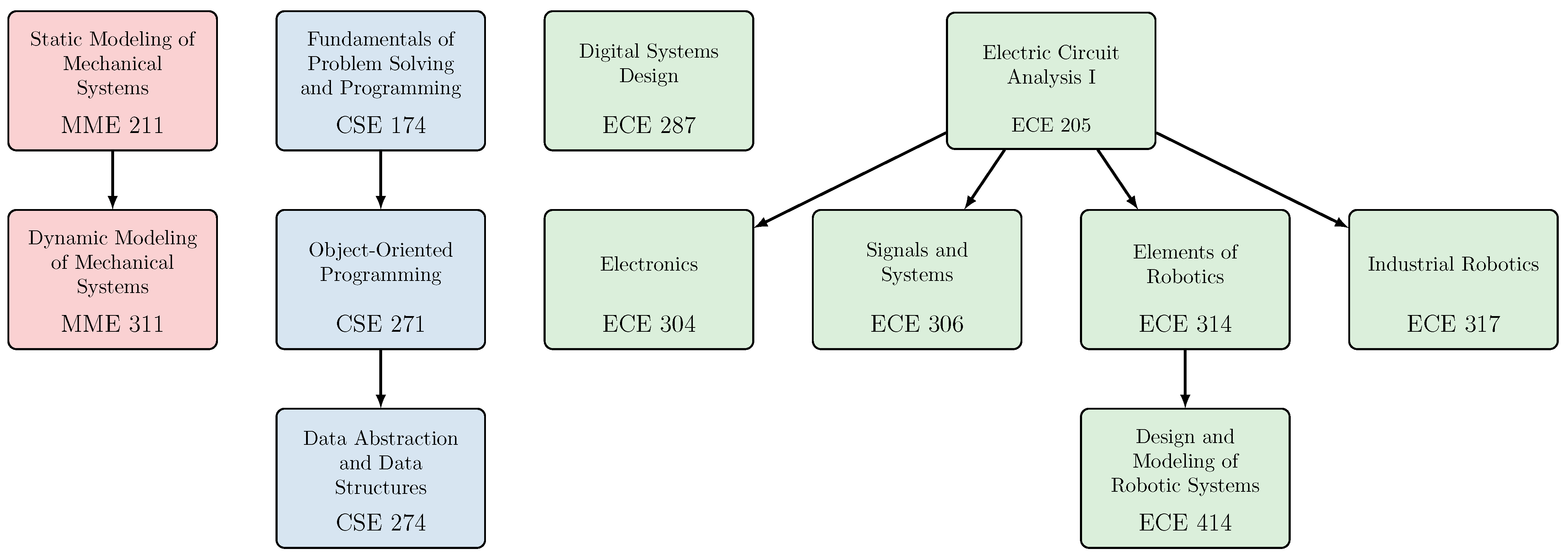
The robotics engineering curriculum at Miami University covers a breadth of robotics fundamentals at the undergraduate level. In the curriculum, students begin with a variety of core requirements, including topics such as calculus, physics, chemistry, technical writing, probability and statistics, and more. Also in their first year, students take CEC 111 and CEC 112: Imagination, Ingenuity, and Impact, a two-semester sequence in which students explore engineering and computing through hands-on, team-based interdisciplinary design projects. Building on this foundation, students in Robotics Engineering take the required courses [
26], shown in
Figure 2 that span the Departments of Electrical and Computer Engineering (ECE), Computer Science and Software Engineering (CSE), and Mechanical and Manufacturing Engineering (MME). Note that an arrow going downwards in the figure represents a prerequisite relationship between courses.
While the required robotics engineering courses span the breadth of robotics, specialties allow students to focus on a particular area of interest. Specialties include Automation, Intelligent Systems, and General Robotics. Since the specialties vary by student, we focus on the courses required by all Robotics Engineering majors.
Beyond standard coursework requirements, each robotics engineering student at Miami University must also complete a capstone design project in which students “conduct major open-ended research/design projects. Elements of the design process are considered as well as real-world constraints, such as economic and societal factors, marketability, ergonomics, safety, aesthetics, and ethics; feasibility studies performed” [
27].
3.2. ABET
The Robotics Engineering degree at Miami University is on the verge of being accredited by ABET (formerly the Accreditation Board for Engineering Technology), the premier accreditation agency for “college and university programs in the disciplines of applied and natural science, computing, engineering, and engineering technology at the associate, bachelor’s and master’s degree levels” [
28].
The driving forces behind each program are its Program Educational Objectives (PEOs), which ABET defines as “broad statements that describe what graduates are expected to attain within a few years after graduation”. Program Educational Objectives are consistent with the mission of the institution and the needs of the program’s constituencies. For the Bachelor of Science in Engineering degree in Robotics Engineering at Miami University, the PEOs are for graduates to achieve the following [
27]:
Success in being employed in an area related to robotics engineering or enrolled in an advanced program.
Advancement in professional skills and knowledge with an understanding of the impact on societal, economic, global, and environmental issues.
Progression in responsibilities by exercising effective communication, leadership, and teamwork skills.
Commitment to professionalism, ethical, inclusive, equitable practices, continuous improvement, and lifelong learning.
3.3. Ohio Robotics Industry
Ohio has a growing industry for robotics, largely due to its history and strength in manufacturing [
29]. In southwest Ohio alone, a variety of robotics companies have made their home including the FANUC America Corporation [
30], DENSO Robotics [
31], Yaskawa Motoman Robotics [
32], and many more [
33,
34,
35,
36,
37,
38,
39,
40,
41,
42]. Along with these companies have come a variety of educational groups and centers for training future roboticists [
43,
44,
45,
46,
47]. Due to its strength in manufacturing, many of these robotics companies in southwest Ohio focus on automation.
4. Methods
We provide four case studies focusing on three senior design projects and one of our focus courses within the Robotics Engineering undergraduate curriculum. For each case, we will
Describe the goal of the project/labs relating them to the RSL model level of learning.
Provide the students’ learning context at this point in the curriculum.
Describe and show the results of the project.
Assess the results of the project/lab, including attainment of the RSL model level(s).
We will do this for each of our four case studies, starting from our senior design projects examined chronologically and ending with our course case study. First, we relate the robotics curriculum to the RSL model, which contextualizes each of the specific results.
5. Project Presentations and Outcomes
5.1. Mapping Courses to the RSL Model
We first map the required Robotics Engineering courses from
Figure 2 to the Robotic System Levels from
Figure 1. Our proposed mapping is shown in
Figure 3. Here, each line connects a required Robotics Engineering course to a layer in the RSL model, with a connection indicating that the course covers material related to the connected layer. For instance, the connection from ECE 205: Electric Circuit Analysis I to
Level 2 indicates that this course covers material in the second layer. We can interpret
Figure 3 in two ways: (i) for any given course, we can use the mapping to identify which layer(s) are covered by the course, and (ii) for any given layer, we can identify which courses cover relevant material. We note that some connections are straightforward, while others are more blurry and open to interpretation.
We make several observations from this mapping between courses and RSL layers. First, the Robotics Engineering curriculum at Miami University covers all seven layers, each of which is connected to at least one course. This does not mean, however, that each layer has significant coverage. For instance, consider Level 4. This layer has two courses: MME 311: Dynamic Modeling of Mechanical Systems and ECE 306: Signals and Systems. These two connections, however, are relatively weak, as neither course focuses specifically on controls (this deficiency has already been identified, and a course focused on controls is being added as a core requirement).
Second, we observe that several courses, particularly those in Computer Science and Software Engineering (CSE), do not directly relate to any of the layers in the RSL model and therefore have no connections. However, this does not necessarily imply that these courses are useless to robotics students, as programming skills are required across nearly all the layers, whether directly or in the design phase.
Finally, we observe that several courses—namely ECE 314: Elements of Robotics and ECE 414: Design and Modeling of Robotic Systems—span the entire RSL model. These courses were designed specifically for the robotics curriculum and form the backbone of the Robotics Engineering curriculum.
5.2. Case Study 1: Capstone Design Project to Create a Centralized Robot Swarm
5.2.1. Goal
Inspired by large-scale swarm robotic systems such as Intel’s spectacular drone show at the Tokyo 2020 Olympics [
48], the goal for this capstone project was to design a multi-robot system with a centralized controller capable of moving in collective motion. This work focused mainly on
Level 1,
Level 2, and
Level 3 of the RSL, as the centralized controller performed higher-level planning and control, and the collective motion was relatively simple.
5.2.2. Student Context
The group consisted of three seniors, two majoring in Electrical Engineering and one in Computer Engineering. The capstone design project was completed over the course of two semesters.
5.2.3. Project Results
For this capstone design project, the students designed and built a small-scale centralized robotic system. Since this problem had a well-defined goal, the students used a waterfall design process in which they sequentially used the requirements to design the system, implemented their design, and then tested and documented the results. Components of the project included the following:
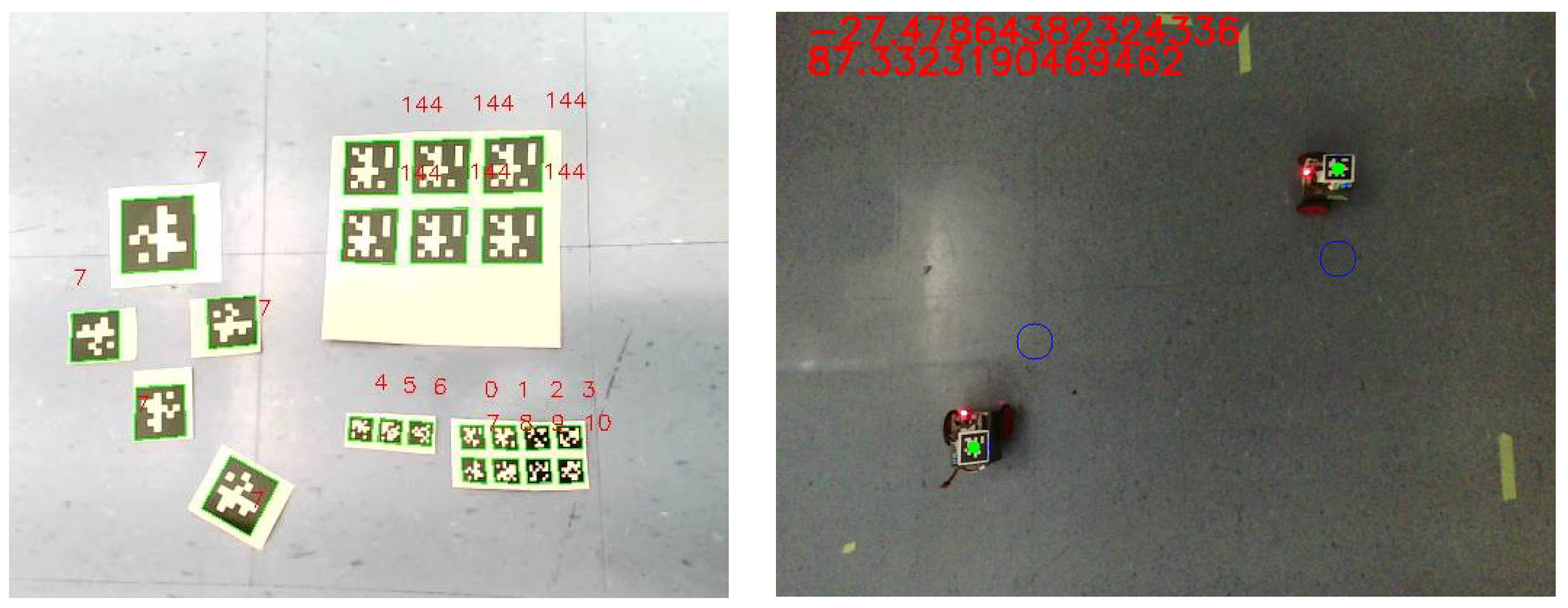
To detect the pose of each robot as well as to send motion commands, the group used an overhead camera system consisting of a Raspberry Pi 4 Model B (with 4 GB of RAM) and webcam. Each robot was equipped with an AprilTag [
50] fiducial marker that the camera system could detect using OpenCV [
51] and the AprilTag library (version 0.0.16) in Python 3.13. The camera system then communicated motion commands to each robot using the User Datagram Protocol (UDP).
As part of the project, the group conducted extensive testing of the accuracy and speed of the image detection system in various scenarios, including multiple heights of the camera above the ground, the number of AprilTags in the visible area, the relative orientation of the AprilTags to the camera, and the sizes of the AprilTags. Moreover, the team analyzed both the accuracy of detection and the rate at which frames were processed in each scenario. An illustration of the AprilTag recognition system is shown in
Figure 4.
While the goal was to scale the swarm to a larger group of agents, the students were able to complete two working robots. Each robot consisted of a BeagleBone Blue microcontroller, prototyping board, custom 3D-printed chassis, and differential-drive wheels controlled with stepper motors as illustrated in
Figure 5 (left).
For the final demonstration of the project, the students programmed the overhead camera system to move two robots to spell the letters “MU”. By equipping the robots with LEDs and capturing the motion with a long exposure, the students produced the image in
Figure 5 (right).
5.2.4. Educational Assessment
The design and implementation of the robotic system covered the entire RSL. The project mainly focused on the lower levels; however, the students spent a majority of the year designing and building the robot itself. For Level 1, the students 3D-printed a custom chassis to facilitate the BeagleBone Blue microcontroller, prototyping board, and stepper motors for the wheels. For Level 2, the students had to study the trade-offs between capacity and discharge rate for lithium polymer (LiPo) batteries in order to select an appropriate battery for the robot. And for Level 3, the students had to interface the BeagleBone Blue microcontroller with the stepper motors using the Robot Control Library, as well receive UDP motion commands from the overhead camera system. We believe the project satisfactorily covered these three layers based on these accomplishments.
As for the higher-level layers, the project required no mission coordination (Level 7) as the single task was to move in the prescribed “MU” pattern. There was minimal planning (Level 6) needed to achieve this, as the centralized camera system computed waypoints along the path for each robot and sent appropriate motion commands to the robots to accomplish this. The students spent significant effort characterizing the camera detection system for perception (Level 5). However, the centralized system did this and was not actually on the robot. And finally, each robot had minimal direct control over its motion (Level 4), as it received motion commands from the camera system that it then applied to its motors.
5.3. Case Study 2: Capstone Design Project to Create a Decentralized Swarm
5.3.1. Goal
Building on the previous project that used a centralized control system, the next project was tasked with designing a
decentralized multi-robot system with no centralized controller, similar to the Kilobot swarm [
52]. Here, the robots should use sensors to achieve autonomous behavior, such as avoiding collisions with other robots and the arena’s walls. This work focuses mainly on
Level 1,
Level 2, and
Level 3 with some higher-level
Level 4 skills as the system needs to deal with feedback and control. This project focused on equipping the robots with sensors to be capable of autonomous behavior, not on implementing complex algorithms.
5.3.2. Student Context
The group consisting of four students with senior standing, one in Electrical Engineering, two in Computer Engineering, and one in Computer Science. The capstone design project was completed over the course of two semesters.
5.3.3. Project Results
Students designed and built a small-scale decentralized robotic system for this capstone design project. As this problem had a more open-ended goal (the particular collective behavior was not specified a priori), the students used an iterative design process in which they repeatedly designed the system, implemented their design, and tested the results. After several iterations of this design procedure, the final components of the project included the following:
Robot vision using a webcam;
Detection of various colors of light to switch between behaviors;
Custom chassis design;
Stepper motors, encoders, and PID control;
Implementation of a leader–follower algorithm.
To achieve autonomous behavior, the students equipped each robot with a webcam. After running tests on the BeagleBone Blue microcontroller, the team decided that the computations were too slow. Therefore, they introduced a Raspberry Pi 4 Model B (with 4 GB of RAM, sourced from DigiKey in Thief River Falls, MN, USA) to the robot to interface with the webcam while still using the BeagleBone Blue for low-level control. With the camera, the robots could sense their surroundings to make decisions. Instead of using AprilTags or QR codes to detect other robots, however, the students chose to surround each robot with colored squares that could be used for pose estimation. This enabled the robots to detect relative pose information quickly using the OpenCV library [
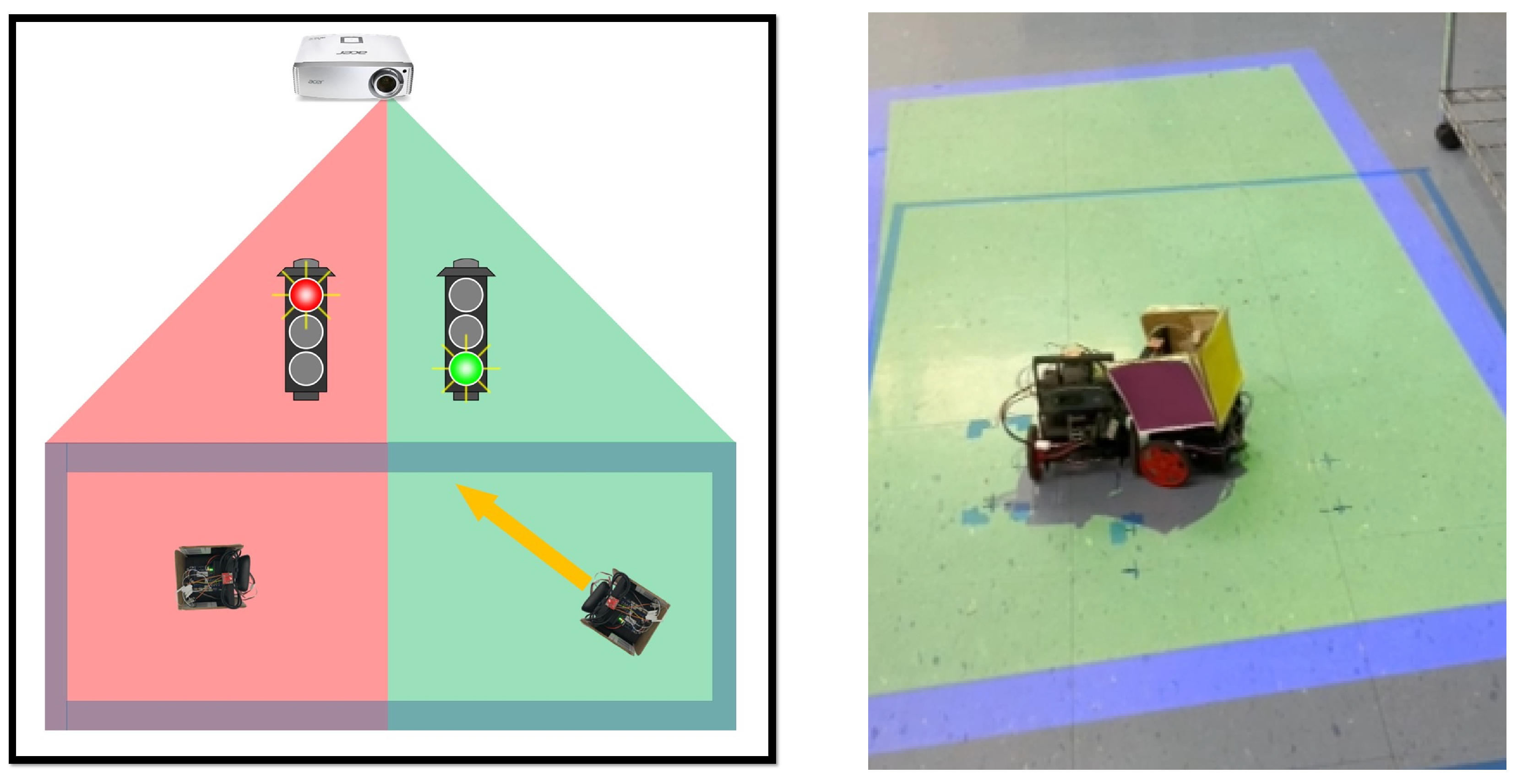
51]. The robots were also equipped with wheel encoders and PID control to ensure accurate motion, as stepper motors may miss steps when the torque is too high. And finally, the robots used a color sensor to detect light from an overhead projector to switch between operating modes; one mode implemented a leader–follower algorithm in which one robot “runs away” while the other “chases it”, while the robots moved randomly in the other mode. An illustration of the final project is shown in
Figure 6.
5.3.4. Educational Assessment
Again, the design and implementation of the robot system covered the entire RSL model, with a focus on the lower levels. The students had to redesign the chassis to accommodate the Raspberry Pi and webcam (Level 1). Also, the students implemented the encoders using photo-interrupters, which needed logic level converters to interface with the BeagleBone Blue (Level 2). At the embedded level (Level 3), the students used the UART communication protocol to interface the BeagleBone Blue with the Raspberry Pi, and I2C to interface the light sensor with the BeagleBone Blue. The students also implemented PID control using feedback from the encoders (Level 4) and pose estimation from the camera (Level 5).
The system required minimal use of the highest two levels, as the leader–follower algorithm was relatively simple and moved straight towards the other robot (Level 6). The light from the projector indicated which mode the robots should operate in (Level 7). We conclude that the project achieved good coverage of the lower levels of the RSL model while only minimally covering the highest levels.
5.4. Case Study 3: Capstone Design Project to Create a Robot Swarm to Implement Flocking Behavior
5.4.1. Goal
Building on the decentralized swarm robotic system from the previous project, the goal of this capstone design project was to design a decentralized multi-robot system in which the robots exhibit flocking behavior using the boids algorithm by Reynolds [
53]; see also [
54].
5.4.2. Student Context
The group consisted of four students with senior standing, three in Computer Engineering and one with a double major in Electrical Engineering and Computer Science. The capstone design project was completed over the course of two semesters.
5.4.3. Project Results
Students designed and built a small-scale robotic system for this capstone design project. While this problem had a well-defined goal, the students ended up using an iterative design process, as their initial designs did not work well when tested. Components of the final project included the following:
Image recognition from an overhead camera system;
Centralized robot control using the overhead camera system;
Light detection to implement various behaviors;
Custom chassis design;
Stepper motors, encoders, and PID control;
Implementation of higher-level control algorithms (e.g., flocking, leader–follower).
This team focused on fast pose estimation. While the AprilTags and colored squares from the previous groups worked, these approaches had issues with regard to speed and accuracy when used for real-time control of the robots. Instead, the group experimented with several other pose estimation mechanisms. As a first attempt, the team constructed a cube with a unique color on each side and LEDs on all corners for fast and accurate detection; see
Figure 7.
The students then detected the pose of the cube using a low-exposure image from the camera and filtering by brightness to detect the corners of the cube based on the LEDs. The orientation could then easily be computed using the face colors. This detection method had issues, however, due to bands in the low-exposure images and the limited radiation pattern of the LEDs.
To achieve fast and accurate pose estimation, the team then designed the OctoTag. Each OctoTag is a square with an inner octagon and triangle corners in complementary colors, as shown in
Figure 8 (top). This unique shape enabled the students to eliminate false detections using a custom detector built in OpenCV, as shown in
Figure 8 (bottom). The detector uses the unique tag geometry to quickly and reliably estimate the pose of the tag. Moreover, the tags are made from construction paper to mitigate reflections and improve accuracy.
Besides pose estimation, the team also made improvements to the robot itself. The team streamlined the design by eliminating the BeagleBone Blue and driving the motors directly from the Raspberry Pi via an H-bridge (L298N). Due to this change as well as different encoders and wheels (due to sourcing issues), the team again redesigned the chassis. The final robot design is shown in
Figure 9.
Equipped with a group of working robots with fast and accurate pose estimation, the team then implemented a flocking algorithm in which robots autonomously choose their heading to move in a similar direction as their neighbors (other robots in their camera’s field of view) while not colliding. To keep the robots in a confined space, the arena’s walls were lined with OctoTags and used for collision avoidance, as shown in
Figure 10.
5.4.4. Educational Assessment
This project focused largely on perception (
Level 5) through several iterations of novel tags for fast and accurate pose estimation. The team also 3D printed a custom chassis (
Level 1), used a Buck converter to power the Raspberry Pi from the battery and H-bridge to power the motors (
Level 2), and interfaced the Raspberry Pi with the camera and other components (
Level 3). There was minimal motor control (
Level 4) based on the encoders, and the path planning (
Level 6) and mission (
Level 7) components were to implement a simple flocking algorithm [
53].
5.5. Case Study 4: Laboratory for Elements of Robotics Course
The laboratory component of ECE 314: Elements of Robotics is closely integrated with the lecture portion of the course, enabling students to apply the fundamental concepts of autonomous mobile robots in a hands-on setting. These concepts include sensors, reactive behavior, finite state machines, motion and odometry, and control. The course then progresses to more advanced robotic algorithms, such as obstacle avoidance, localization, and mapping, and an introduction to the role of machine learning and deep learning in solving complex robotic challenges.
The labs are designed to be practical and engaging, with students assembling a differential drive robot using an affordable Arduino robot kit, as shown in
Figure 11. In our case, we used the Vkmaker smart robot car chassis Kit with an UNO R3 Module and some additional parts that we purchased separately for Labs 1–5. This hands-on approach allows them to implement and test the concepts they learn in the classroom directly on the robot they build. There are 11 labs throughout the course, as follows:
Lab 1–Lab 5 spans an introduction to Arduino, followed by integration and characterization using various sensors: light, thermal, ultrasonic range, servo and stepper motors, IR remote controller, and I2C LCD 1602 module.
Lab 6–Lab 11 involves building a differential drive robot capable of stopping and starting the Arduino robot with a remote controller and driving it approximately straight, initially in an open-loop setting using optical encoder wheels, then driving it straight with interruptions using closed-loop control, followed by obstacle avoidance, making turns. The last lab is to implement any project by building upon the knowledge of previous labs and some of the fundamental robotics concepts learned during the course.
For this case study, we focus on the final two labs, where students synthesize their learning of robotics principles and how to go from theoretical algorithms to the behavior of a real robot. It is worth noting that, as in many typical lab courses, the complexity of the labs builds on previous labs. For Lab 10 as a subcase, we find the following:
5.5.1. Goal
Program the differential drive robot to navigate freely in the environment without colliding with obstacles.
5.5.2. Student Context
The lab is designed for the students of the ECE 314 course to work independently, building on the knowledge gained from previous labs and course material. This course is typically taken by juniors and is required for students majoring in Robotics Engineering. The ECE 314 course is one semester long.
5.5.3. Typical Lab Results
For this lab, the students have to revise their previous robotics program so that when the robot is moving in the forward mode, it has to stop if it detects an obstacle within a specific range of the ultrasonic sensor. The servo motor attached to the ultrasonic sensor rotates right and left to check for obstacles. Then, the robot has to turn in the direction where no obstacle is detected and keep moving forward.
The components required for this lab are as follows:
Arduino robot kit.
Ultrasonic sensor.
Remote controller.
IR receiver.
LCD display.
Wheel encoders.
Optical speed sensors.
Servo motor.
To program the robot for obstacle avoidance, the students previously implemented a program with an interrupt routine using either a P Controller, PI Controller, or PID Controller so the robot can move straight forward or backward. An IR receiver and a remote control are used to control the robot in different states, such as forward, backward, and stop. To implement the turns in the differential drive robot, students use wheel encoders that use wheel counters to determine the angle of a turn.
For example, to make a 90-degree left turn, the right wheel counter keeps track of right wheel rotations (cntrR), the number of wheel encoder counts required per degree of rotation (cntrPerDegree), 90 being the desired turn angle in degrees, and a 0.5 rounding factor to avoid floating point inaccuracies. The corresponding formula would be
It requires information on the wheel circumference, C = 2 R, where R is the wheel radius, and the wheel separation between the left and right wheels (D). When the robot turns in place, each wheel moves along a circular arc of radius D/2. Additionally, the encoder and the optical speed sensors provide counts per complete wheel revolution.
Students have to demonstrate their lab, and the score will depend on the robot’s performance. The demonstration includes that when the robot encounters an obstacle in front, the corresponding distance from the object has to be displayed on the LCD screen, and the robot has to stop. One must check the right and left of the robot using the ultrasonic sensor and servo to rotate it, and move it in a direction that does not have an obstacle. This demonstration should last at least 30 s without colliding with obstacles in a high-speed setting. Students use the IR remote to stop the robot’s movement when needed.
5.5.4. Educational Assessment
The lab design and implementation covered Level 1, Level 2, and Level 3 which involved building the differential drive robot from making use of Arduino robot kit in the beginning labs and integrate the Arduino microcotroller board with all the required sensors such as ultrasonic sensor, remote controller, IR Receiver, LCD Display, L298N drive module, Wheel Encoders, optical speed sensors, and Servo motor to ensure their functionality by implementing simple labs.
In this particular lab, the students focus on Level 4, where they implement a PID controller to control the motion of the robot wheels and drive as straight as possible in both forward and backward motion. Wheel encoders and optical speed sensors should make perfect 90-degree turns to either left or right to avoid obstacles when an object is detected in front using an ultrasonic sensor, and navigate freely in the environment.
For Lab 11 as a subcase, we find the following:
5.5.5. Goal
Develop a maze-solving differential drive robot using local navigation and one of three obstacle-avoidance algorithms: wall following, wall following with direction, or the Pledge algorithm covered in the ECE 314 lecture.
5.5.6. Typical Lab Results
For this lab, students must revise their previous programs and implement one of the obstacle-avoidance algorithms. They have to design their own maze and implement the algorithm to exhibit it in action. The simplest algorithm is the wall-following algorithm, and the complex is the pledge algorithm. Students are graded on the difficulty, effectiveness of the algorithm, and the quality of implementation. The components required for this lab are the same as those in the previous lab.
Starting with a simple wall-following algorithm, the students have to keep track of states using the knowledge of finite state machines and implement the wall follower. They can slowly progress into adding heading or direction perspective, where they keep track of left and right turns. Building on the previous labs, where they had good control over the robot movement and the turns made, this lab focused on the obstacle-avoidance algorithm implementation, and it is working.
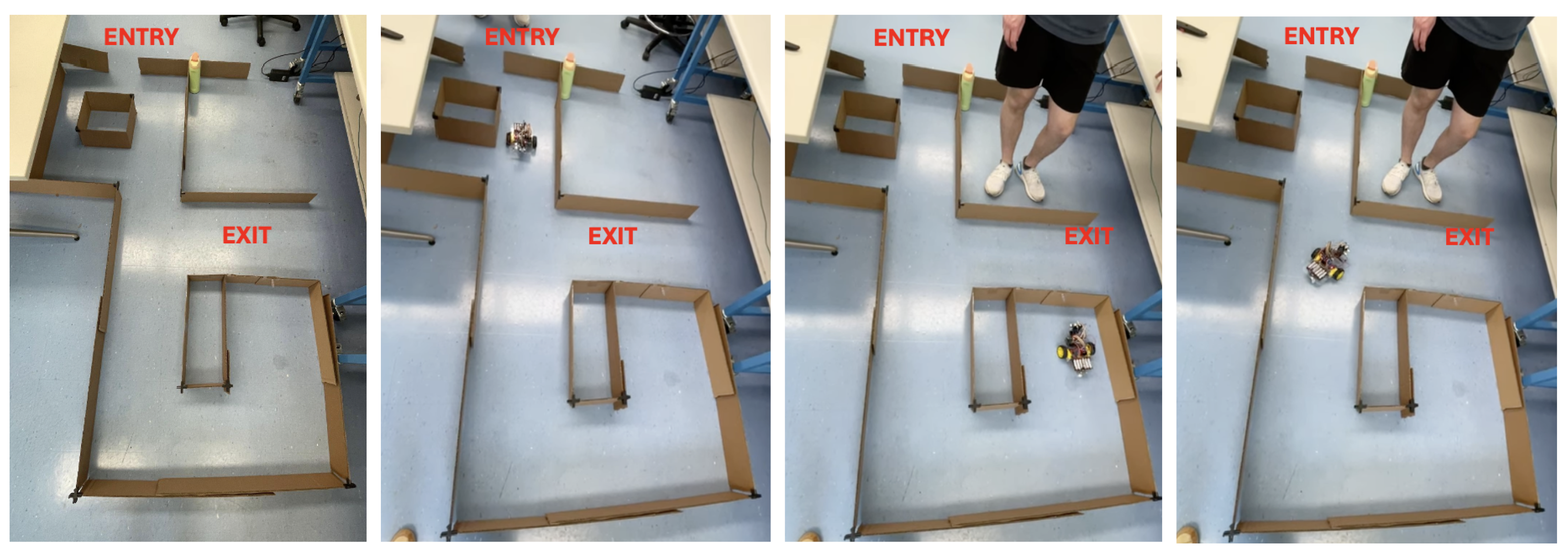
The goal is to advance the current state of the robot to perform in
Figure 12, which shows the maze built by one of the groups and the pledge obstacle-avoidance algorithm implemented. The robot keeps track of its direction; when the robot turns left, a 90-degree heading is added to the robot’s direction, and a −90-degree heading is added when the robot makes a right turn. Therefore, when the total heading is equal to 0-degree, the robot goes forward, and when the heading is not 0-degree, the robot turns right. The goal is to prevent the robot from getting stuck going around islands or getting trapped in loops, and to exit the maze nicely. Additionally, an LCD can be used to display the robot’s heading, and an IR remote controller can be used to do an emergency stop if needed.
5.5.7. Educational Assessment
All the initial labs of ECE 314 before lab 11 covered lower RSL model levels from Level 1 to Level 4. This started with students building an Arduino differential drive robot and integrating multiple sensors with the microcontroller, ensuring their functionality. They also implemented a PID controller to make the robot go as straight as possible in both forward and backward directions by balancing its wheel speeds. Also, it can make perfect wheel rotations during turns with the help of wheel encoders. In this particular lab, their focus is on a low-level obstacle-avoidance algorithm implementation where they navigate in a maze environment autonomously by keeping track of the robot’s direction and making sure not to be trapped in the islands and loops and to successfully come out of a maze which can be Level 4 or an introduction to the concepts of Level 5.
6. Discussion
Each of the capstone design projects involved many levels of the RSL model, which is to be expected from a culminating design experience. However, based on the project’s goals, some levels were emphasized more than others. Case Studies 1 and 2 focused almost entirely on the lower levels (Level 1–Level 4), while Case Study 3 focused mainly on perception (Level 5). In particular, none of these projects could focus on the highest levels (Level 6 and Level 7). We propose that this is due to the students spending much of their time working on low-level tasks, such as making a wheel spin or reading the value of an encoder. Similarly, the course as a case-study also focused on first-principle robot design and included low-level focus (Level 1–Level 4).
One way to prioritize higher levels would be to start from a pre-engineered off-the-shelf robotic system. For example, the QBot from Quanser [
55] is an autonomous ground robot that is equipped with a differential drive motion system along with a vast array of sensors, including LiDAR, Intel’s RealSense camera, a downward-facing camera, a gyroscope, and an accelerometer. Systems like this jump-start students past the lower levels of designing the robot hardware and instead allow students to focus on high-level tasks such as task- and trajectory-planning, perception, and sensor fusion. These systems come at a cost, however, as pre-engineered systems can be expensive. As an intermediate approach, systems such as the TurtleBot [
56] offer an integrated robot at a more affordable cost. Use of any such system, however, removes the need for students to understand the lower levels of the RSL model, leading to a trade-off. As an educator, it is important to understand at which levels students should spend their time and effort, and then design appropriate projects based on the identified priorities.
In light of our proposed RSL model, one may ask whether or not a robotics curriculum should have balanced coverage among the various layers. One response to this question is that the local industry should drive the curriculum focus (which we elaborate on in the following paragraph). With the explosion of advancement in Artificial Intelligence (AI) and other design tools, another consideration is to what extent available tools are able to sufficiently solve problems in a particular layer, alleviating the need for students to have mastery of low-level computations vs. high-level understanding.
Based on our analysis, we recommend that undergraduate robotics programs drive their curriculum based on their overall objectives and where their students serve in the industry. For example, our students will head out into robotics fields where the focus is not primarily on creating robots but on how robots can be used in manufacturing. For these goals, one or two embedded system-focused robotic courses are reasonable, but we do not recommend that much more time be spent on these types of educational projects; instead, higher RSL model levels should be the focus of our education system. Balancing hands-on embedded systems experience with higher-level robotics concepts in curriculum development requires careful coordination between required courses, laboratories, capstone design projects, and other student experiences.
7. Conclusions
In this work, our team looked at senior capstones and a course within our robotics engineering undergraduate curriculum. Our lens for the case studies was to see what activities students focus on for our newly introduced RSL model of robotics education. In each case, we examined how the project or lab was conceived (at what level), described typical activity results, and then provided a post-analysis of the RSL model levels for the completed work. Much of our education is at Level 1, Level 2, and Level 3. Students spend significant time at these levels dealing with getting the base components working, and we might argue that, because of the low-cost constraints in this education space, the extensive time spent here is not of significant value to the learning engineer.
Additionally, our program goals, as provided by our educational context, suggest that our education time is too long in these low-level spaces. Instead, for our program, we should seek methods to allow students to spend more learning time at some of the higher levels of the RSL education model. For the community of educators, we believe this work provides a grounded approach to planning future robotic curricula at the undergraduate level. Additionally, existing curricula can leverage our model, with their own goals, to evaluate and frame what their learners should be doing.


