Abstract
The construction of high-rise buildings necessitates efficient and reliable material transport systems to improve productivity and reduce labor-intensive tasks. Traditional methods such as cranes and elevators are widely used but are often constrained by high costs and spatial limitations. Manipulator-based robotic systems have been explored as alternatives; however, they require complex control algorithms and struggle with confined construction environments. To address these challenges, we propose a lifting robot designed for repetitive inter-floor material transport in construction sites. The proposed system integrates a gear-connected double parallelogram linkage with a crank-rocker mechanism, enabling one-degree of freedom (1-DOF) operation for simplified control and precise positioning. Additionally, a spring-cable-based gravity compensation mechanism is implemented to reduce actuator torque, enhancing energy efficiency and structural stability. A prototype was fabricated, and experimental validation was conducted to evaluate torque reduction, positioning accuracy, and structural performance. Results demonstrate that the proposed system effectively minimizes driving torque, improves load-handling stability, and enhances overall operational efficiency. This study provides a foundation for developing automated lifting solutions in construction, contributing to reduced worker strain and increased productivity.
1. Introduction
The construction of high-rise buildings has become a dominant trend in the modern architecture industry [1,2,3]. However, material transportation within construction sites remains a labor-intensive task, often requiring workers to manually transfer heavy materials between floors. This process not only increases the risk of musculoskeletal disorders among workers but also results in inefficiencies that extend construction timelines [4,5]. In particular, transporting materials such as formwork and scaffolding, which are essential for concrete construction, presents significant challenges when transitioning from one floor to the next [6].
To address these challenges, several automated material handling solutions have been developed and implemented in the construction industry. Cranes and elevators are commonly utilized in large-scale projects; however, their deployment is often constrained by high costs and spatial limitations. For instance, traditional stacker cranes are limited to operating one at a time within a single aisle, resulting in slower throughput and reduced efficiency [7,8]. Additionally, tower cranes are highly effective for continuously lifting large volumes of materials in large-scale construction sites; however, they can lead to excessive energy consumption during smaller-scale operations [9].
Autonomous mobile robots (AMRs) and manipulator-based robotic systems have also been explored as potential alternatives [10,11]. AMRs can significantly reduce the need for manual labor by automating material handling tasks, thereby freeing employees to focus on more complex, value-added activities. However, these systems often require complex control algorithms and may face challenges in autonomous navigation, especially in unstructured environments [12,13,14,15]. Additionally, AMRs and mobile manipulators may struggle to operate efficiently in confined spaces with floor openings, as precise positioning and maneuvering in such environments remain significant hurdles.
In summary, while automated solutions like cranes, elevators, AMRs, and robotic manipulators offer promising avenues for improving material handling in construction, their practical application is often limited by factors such as cost, spatial constraints, complex control requirements, and operational challenges in confined or unstructured environments.
To overcome these limitations, a lifting robot specifically designed for repetitive inter-floor material transport in construction sites is proposed in this study. The proposed system employs a gear-connected double parallelogram linkage combined with a crank-rocker mechanism, enabling one-degree of freedom (1-DOF) operation. This configuration significantly simplifies control while maintaining high positional accuracy during material transport. Furthermore, a spring-cable-based gravity compensation mechanism is incorporated to reduce the required actuator torque, thereby improving energy efficiency and structural stability.
The main objectives of this study are as follows:
- ①
- To develop a lifting robot capable of automated, repetitive material transport between floors with minimal control complexity.
- ②
- To implement a gravity compensation mechanism that enhances system efficiency by reducing actuator capacity requirements.
- ③
- To optimize the pulley positioning mechanism to accommodate varying load conditions.
- ④
- To fabricate a prototype and experimentally validate its performance in terms of torque reduction, structural stability, and positioning accuracy.
By addressing these objectives, the proposed system demonstrates the feasibility of integrating automated lifting solutions into construction sites, ultimately reducing the physical strain on workers and improving overall productivity.
In the remainder of this paper, Section 2 describes the mechanical configuration of the proposed lifting robot, while Section 3 details the gravity compensation mechanism. In Section 4, a prototype is fabricated, and the proposed gravity compensation mechanism is implemented. Section 5 presents the analysis and discussion of the experimental results, focusing on the effectiveness of the gravity compensation mechanism. Finally, Section 6 concludes the study, summarizing the key findings and suggesting future work.
2. Mechanical Configuration of the Lifting Robot
In tasks where objects are simply transported to upper floors, utilizing the shortest path between levels, the vertical direction, is ideal. Therefore, a specialized design capable of repeatedly transporting objects along a vertical path is needed.
2.1. Gear-Connected Parallelogram
The double-parallelogram mechanism is commonly used in palletizing robots due to its ability to maintain a specific angle relative to the ground during motion [16]. However, the proposed lifting robot only requires repetitive vertical movement along a single path, eliminating the need for three degrees of freedom. Therefore, two parallelogram linkages were connected using gears, reducing the degrees of freedom to one. Figure 1 shows a schematic design of the proposed lifting robot. The base is positioned on the upper floor. In the initial posture of the robot (, as shown in Figure 1b, the load platform is located on the lower floor, ready to load materials. Due to the characteristics of the parallelogram structure, the load platform, positioned at the distal link, maintains a horizontal orientation relative to the ground during motion. The driving target is the position where the distal link reaches the base, at which point materials are transferred. Here, L represents the length of the rotating link, A and B denote the offsets between the rotating links, C indicates the distance between the gears, and represents the rotation angle of the rotating link. Then, the rotation angle of the rotating link and the stroke of the load platform at the driving target are calculated as follows:
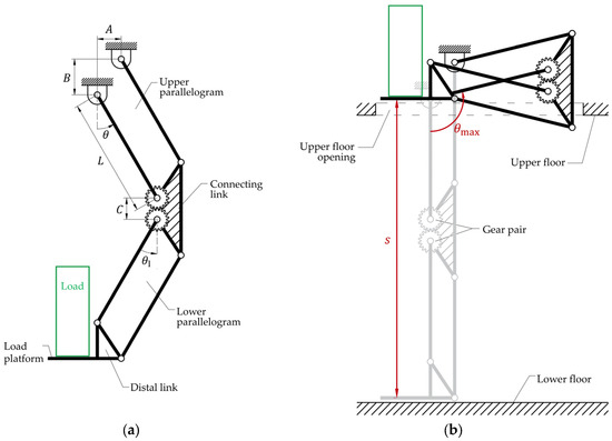
Figure 1.
Schematics of the proposed lifting robot: (a) and (b) .
To reach the driving target, as shown in Figure 1b, the two parallelogram linkages and components must operate without interference, even in overlapping regions during their motion. To achieve this, as illustrated in Figure 2, the lower rotating links were designed with a smaller width compared to the upper rotating links . As a result, an appropriate offset was applied between the motion planes of the upper and lower rotating links, ensuring collision-free operation.
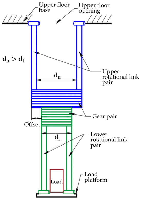
Figure 2.
Side view schematic of the proposed lifting robot.
2.2. Crank-Rocker
In construction sites, the rapid and repetitive transport of materials is essential [17]. To achieve efficient and reliable transport in such environments, mechanisms with simple and robust designs are needed. The proposed gear-connected parallelogram mechanism has a 1-DOF, requiring only a single motor for actuation. Even if another 1-DOF structure is added to the system, it can still operate with the same single degree of freedom control. To achieve this, a crank-rocker mechanism, which is widely recognized for its excellent performance in efficiently implementing repetitive motion in various mechanical systems, is applied to drive this structure. By employing the crank-rocker mechanism, repetitive motion within a specific range can be realized with a simple structure, minimizing the complexity of control [18].
As shown in Figure 3, a crank-rocker mechanism can be attached to the rotating link of the upper parallelogram for actuation. The lengths of the links that constitute the crank-rocker mechanism are determined to satisfy Grashof’s condition and enable repetitive motion between and . To satisfy Grashof’s condition, which determines whether a four-bar linkage can achieve full rotation of a designated link, the following condition must be met:
where is the shortest link length, is the longest link length, and and are the remaining two link lengths. In this design, as shown in Figure 3, the crank link is the shortest link, and the base link is the longest link.
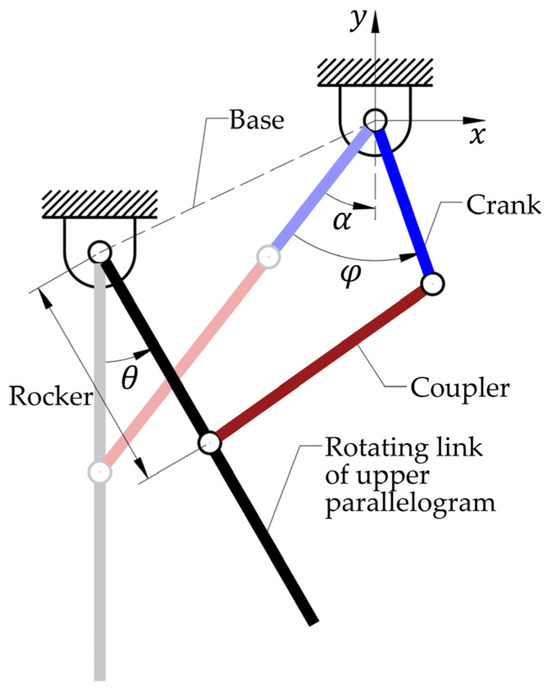
Figure 3.
Concept diagram of the crank-rocker applied to the upper rotating link. When the crank link rotates by , the rotating link rotates by .
Furthermore, the two singular positions of the crank-rocker mechanism are set such that the angle of the rocker satisfies and at each singular position. By configuring the crank angle to reach its singular positions at and , the mechanism is designed to ensure equal time durations for the lifting and lowering motions, enabling smooth and consistent operation. Furthermore, at these two singular positions, the instantaneous velocity of the distal link becomes zero, so that the system can be suitable for collaborative tasks with workers without further control. The posture of the robot corresponding to the crank link rotation is shown in the schematic diagram in Figure 4.
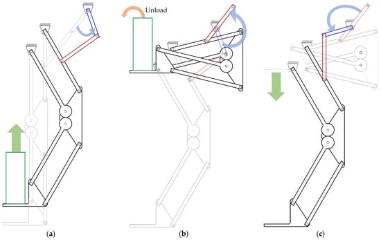
Figure 4.
Concept diagram of one cycle operation: (a) Ascending motion, (b) Material unloading, (c) Descending motion.
3. Spring-Cable-Based Gravity Compensation
3.1. Necessity of Gravity Compensation
The designed lifting robot is intended for use in construction sites, where it operates in the same workspace as human workers. Therefore, it is essential to minimize any potential risks posed to workers within the operating environment. The use of high-capacity actuators for robot operation not only directly affects the safety of the system but also significantly increases the overall cost of the robot. Several studies have investigated the implementation of spring-cable mechanisms for gravity compensation in robotic systems, aiming to reduce actuator loads and enhance structural stability in repetitive tasks. For instance, Suh and Choi (2019) developed a gravity-compensated tool handler designed for a hair-implanting device, effectively reducing torque requirements during repetitive operations [19]. Similarly, Lee and Seo (2017) proposed a wire-driven gravity compensation mechanism that minimized actuator capacity in multi-DOF manipulators through passive balancing [20]. Consequently, implementing a gravity compensation mechanism in the designed lifting robot is crucial to effectively reduce the torque required for actuation, thereby allowing for the use of lower-capacity actuators.
Meanwhile, since the proposed robot has a 1-DOF structure constrained by gears, applying gravity compensation only to the upper parallelogram linkage allows for the adjustment of the torque required to drive the entire system as desired [21]. However, because the load platform, which transports materials, is positioned at the end of the lower parallelogram, a significant torque can be generated at the gear-connected joints when carrying heavy materials. As a result, the lower parallelogram linkage may become structurally vulnerable. Therefore, by applying appropriate gravity compensation to the lower parallelogram linkage as well, the torque transmitted through the gears can be regulated, thereby the overall structural stability of the robot can be enhanced [19]. To achieve this, in this thesis, a mechanical gravity compensation mechanism utilizing a spring and cable is introduced.
3.2. Cable Path Design
Figure 5 illustrates the spring and cable path designed to apply gravity compensation to the proposed robot. The spring is fixed externally near the base of the robot, and the red-colored line represents the extended cable path connected to the spring. The extended cable passes through idle pulleys positioned on both the upper and lower rotating links, transmitting the elastic energy of the spring. As the robot’s posture changes, the length of the spring varies. Since it is simultaneously tensioned by both parallelogram linkages, the elastic energy of a single spring can be effectively utilized over a larger range.
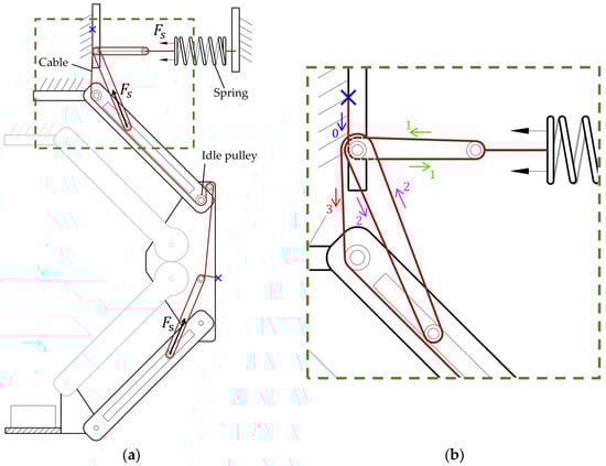
Figure 5.
Cable path design for spring elastic energy transmission: (a) Overall cable path, (b) Detailed path of the green box section. The cable passes through the spring, the pulley on the link, and the fixed pulley on the rotating axis in sequence.
Meanwhile, since the length of the cable wound around the pulley remains constant regardless of the robot’s posture, the size of the pulley does not affect the elastic energy transmitted to the robot [20,22]. Furthermore, because the spring is located outside the robot and a thin cable is used instead, the robot can be designed with a narrower width. This allows for easier adaptation to constrained environments, such as maneuvering through narrow openings in actual construction sites. To calculate the torque compensated at the joints by the force transmitted through the cable, the upper and lower parallelogram linkages were modeled as a single equivalent rotating link, as shown in Figure 6, and analyzed using a static equilibrium model. Here, the deformed lengths of the spring, due to the lower parallelogram linkage and due to the upper parallelogram linkage , are determined by the positions of the pulleys and the distances between them ( and ), as expressed in the following equations.
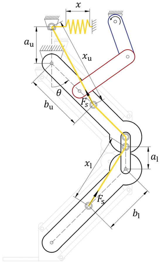
Figure 6.
Simplified gravity compensation static model.
Based on the above equation, the length of the spring can be calculated as follows, considering the initial deformation length .
As a result, spring force which is equivalent to the cable tension, can be expressed as follows:
where k denotes spring constant.
In order to calculate the torque required to maintain the robot’s posture at the driving joint, the torques at the gear joint and the upper rotating link joint have to be calculated based on the robot’s posture. First, as shown in Figure 7a, the torque is transmitted through the gears , which results from the loads of the lower rotating link , the distal link , and the transported material , and the cable tension is calculated as follows:
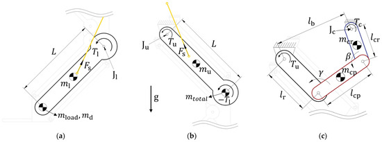
Figure 7.
Simplified static model of each rotating link: (a) Lower rotating link, (b) Upper rotating link, (c) Crank-rocker.
Then, as illustrated in Figure 7b, the torque at the upper rotating link joint is calculated by considering both the torque transmitted through the gears and the torque induced by the robot’s self-weight and the cable tension as follows:
Consequently, the torque required to maintain the robot’s posture at the driving joint of the crank-rocker mechanism can be calculated based on the kinematic relationships of the four-bar linkage, along with the elements in Figure 7c and the previously determined torque from Equation (11) as follows:
3.3. Compensation Force Determine
The robot proposed in this study follows a cycle in which it loads materials when load platform is on the lower floor, transports them to the upper floor, and then returns to the lower floor as Figure 4. Consequently, the load on the load platform varies within a single cycle. By considering this load variation and utilizing Equation (12) to ensure that the maximum torques in the presence and absence of are equal as , the required driving torque can be minimized, thereby reducing the actuator capacity. Under this condition, the optimal that minimizes the driving torque can be determined based on the parameters that define the compensation torque, and it is calculated as follows.
To ensure that Equation (13) has a unique solution, the parameters are set as and for an arbitrary positive constant . Additionally, by defining , the equation can be rearranged as follows.
In other words, the magnitude of gravity compensation that minimizes the required driving torque for handling a specific load is determined by the pulley positions of the upper rotating link and , as well as the pulley position ratio between the upper and lower rotating links .
3.4. Adjustable Parameter
In actual operations, various materials with different loads, as listed in Table 1, need to be transported. If the magnitude of gravity compensation is too small when dealing with heavy materials, a higher actuator capacity is required. Conversely, if the gravity compensation is excessively large when handling lighter materials, energy efficiency decreases. Therefore, by adjusting the level of gravity compensation according to different material loads, overall energy efficiency can be improved. Nguyen (2022) introduced a gear-spring mechanism specifically designed to handle variable payloads, demonstrating the feasibility of achieving consistent gravity compensation across varying load conditions [23]. Additionally, Kim et al. (2023) explored robust and agile legged locomotion using a spring-cable structure to maintain equilibrium under dynamic loading condition [24], highlighting the potential of passive mechanisms for adaptive gravity compensation in repetitive tasks.

Table 1.
Weight of materials to be transported [6].
To achieve this, adjustable design parameters for gravity compensation control are analyzed. First, consider the condition related to the initial length of the spring , as described earlier. When the spring remains fixed, this condition cannot always be satisfied if and change simultaneously. Therefore, must be set as a fixed value, and only one of or should be adjustable. Since is fixed near the base while is positioned on the robot’s link, it is reasonable to adjust to regulate the magnitude of gravity compensation. Secondly, the condition for is satisfied only when varies within a range greater than . Therefore, the initial value of , denoted as , must always be greater than .
3.5. Parameter Optimization
Meanwhile, an optimization process can be applied to determine and . Here, since directly influences the torque compensated for the lower rotating link, adjusting appropriately allows for control over the torque transmitted through the gears. Therefore, by constraining the torque applied to the gear teeth within a certain range, gear damage can be prevented, and the structural stability of the mechanism can be enhanced.
Assuming that the tensile stress of the gear material is , and given that the module of the gear is and the number of teeth is , the pitch radius is defined as . Additionally, if the gear width is , the tooth thickness can be calculated as follows.
The cross-sectional area of gear tooth can be calculated as follows.
As a result, the allowable load can be calculated as follows.
Consequently, the allowable torque to prevent gear failure is calculated as follows.
Utilizing this, the first constraint can be expressed in two forms according to the work cycle, as follows.
Next, it is necessary to consider the feasible range for adjusting . First, as mentioned earlier, must satisfy . Additionally, cannot be positioned beyond the length of the rotating link. Therefore, the maximum value of must satisfy . Since is determined based on the position of , the minimum and maximum load values that can be handled can also be determined accordingly. Consequently, another constraint can be established, which is expressed as follows for the cases when and , respectively.
The objective function can be defined as the deviation of as follows.
By selecting the values of and that maximize the objective function while satisfying the four aforementioned constraints, the range of loads that can be handled is maximized. At the same time, an appropriate compensating force can be applied to the robot to ensure the stability of the gear connection.
4. Verification
4.1. Prototype Fabrication
To verify the structural design and gravity compensation performance of the proposed robot, a small-scale prototype was fabricated, as shown in Figure 8. Most of the standard components, such as bearings, were sourced from MISUMI Korea, while non-standard components, including gears, were fabricated using a 3D printer from Markforged, Inc. (Waltham, MA, USA) with Onyx material.
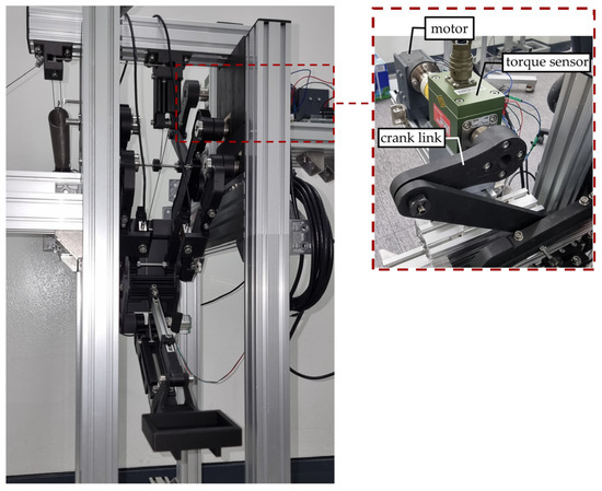
Figure 8.
Fabricated lifting robot and detailed view of the actuation part for experimental validation: Torque sensor installed between the motor and the crank link to measure the required motor torque.
The length of the rotating link was set to , with offsets between the rotating links of and . The upper and lower rotating links were connected using gears with a module of 2 and 18 teeth, resulting in . Based on Equations (1) and (2), the vertical travel distance was determined to be , and the maximum rotation angle of the rotating link was calculated as . As explained earlier in Figure 2, the width of the lower rotating link pair is narrower than that of the upper rotating link pair, allowing for operation without component collisions. The weights of the upper and lower rotating links were measured as and , respectively, while the weight of the connecting link was measured as . The weight of the distal link, including the material load platform, was measured as .
For the crank-rocker mechanism, the rocker link was set at the midpoint of the upper rotating link so that , and the position of the crank joint was determined to prevent component collisions during operation. The length of the fixed frame was set to . The lengths of the crank link and coupler link were then fabricated as and , respectively. By setting the link lengths in this manner, the mechanism satisfies Grashof’s condition as expressed in Equation (3), allowing for the complete rotation of the crank link without interference. Furthermore, this configuration ensures that the system reached singular postures at and , with the rocker angles satisfying and at these positions. The measured weights of the crank and coupler links were and , respectively. Moreover, a Dynamixel XH540-W270-R motor (Robotis Co., Ltd., Seoul, Republic of Korea) with a stall torque was used to actuate the crank link.
The spring used for gravity compensation had a stiffness of , a free length of , and an initial tension of . The cable, which extends from this spring to transmit elastic energy to the robot, was made of SS304 with a maximum tensile strength of , a diameter of , and a 7 × 19 strand structure. The idle pulleys guiding the cable have a diameter of .
Based on the specifications of the fabricated robot and spring, the gravity compensation parameter optimization process described in Section 3.5 can be performed. The Onyx material used for gear fabrication has a measured shear strength [25]. Therefore, the tensile stress is assumed to be . With the gear width designed as , the allowable torque is calculated as using Equations (15)–(18). Applying a safety factor of 3.7, the allowable torque is determined to be . The maximum value of denoted as , was set to considering the link length and component arrangement. At this setting, the minimum and maximum loads to be handled were determined as and , respectively, by scaling down the minimum and maximum values from Table 1, originally and . Therefore, these values are substituted into the constraints given by Equations (19)–(22).
Figure 9a presents a graphical visualization of the constraints, while Figure 9b illustrates the feasible range that satisfies these constraints. Figure 9c shows a three-dimensional graph representing the objective function values for the feasible combinations of and . From this process, the optimal values that maximize the objective function were determined as and . Consequently, was determined to be . As is adjusted from to , is proportionally adjusted from to according to the -ratio. This configuration allows for handling loads ranging from to .
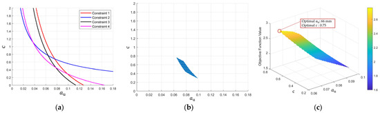
Figure 9.
Results of the design parameter optimization process: (a) Constraints, (b) Feasible region, (c) Objective function values for feasible parameters.
To adjust and , holes were created, as shown in Figure 10, allowing for the manual adjustment of the movable pulley positions. By positioning the pulleys at different points, the elastic energy exerted by the spring on the rotating links is modified, thereby increasing or decreasing the appropriate load capacity. The control strategy employed in the proposed lifting mechanism is structured as a simple repetitive operation loop. The flowchart in Figure 11 illustrates the control sequence, comprising three main cycles: initialization, mode setting, and repetitive operation. During the initialization cycle, the system moves to the initial position, sets the load weight, and adjusts the pulley position based on the detected load. In the mode setting cycle, the pulley position is further adjusted according to the specified load. Once the mode setting is complete, the repetitive operation cycle begins. The repetitive operation cycle involves continuous rotation of the crank link to execute material transport tasks based on the defined pulley position and load weight.
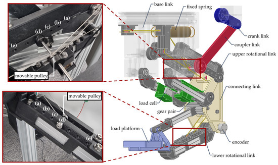
Figure 10.
Upper and lower movable pulley positions determined by the optimization process.
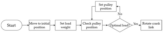
Figure 11.
Control flowchart of the lifting robot: The control sequence consists of three main loops —initialization, mode setting, and repetitive operation.
Spring was pre-tensioned by 63.96 mm to satisfy the zero free length condition. According to Equation (8), when is at its initial position of , the spring is stretched from to . At the final position of , the spring extends from to . In the experiment, considering the safety margin, testing was conducted only up to . Figure 10 illustrates the movable pulley positions corresponding to Table 2, where the idle pulleys can be repositioned accordingly. Since the cable length remains fixed, the initial length of the spring is adjusted to satisfy the required conditions as the pulley positions change. In addition, to bridge the gap between the theoretical gravity compensation and that of the actual prototype, a 250 g weight was used for calibration.
Table 2.
Theoretical optimal load according to each pulley position.
4.2. Driving Torque
First, the variation in the required driving torque under the appropriate load conditions was evaluated to determine whether the designed mechanism effectively reduced the driving torque. As shown in Figure 12, during the experiment, the motor rotated at a constant speed of 2 rpm in a clockwise direction for one full revolution, while the load was applied at the lowest position and removed at the highest position. Three repeated trials were conducted for each experiment. During this process, a rotary torque sensor was installed between the motor and the crank link, as depicted in Figure 8, to measure the required driving torque. The torque sensor used was the BRDM-N10 model from Bongshin Loadcell Co., Ltd. (Osan, Republic of Korea), with a rated capacity of 10 Nm. The motor angle was measured using the built-in encoder, which has a resolution of 0.0879° (4096 PPR). Since the motor operated at a slow speed of 2 rpm, the process can be assumed to be quasi-static. Experiments were conducted for each movable pulley position with its corresponding optimal load, and the results are presented in Figure 13. The maximum measured torque values for each condition are summarized in Table 3. To visually verify the effectiveness of the gravity compensation mechanism, the theoretical torque required for operation without gravity compensation was plotted in Figure 14 for each load condition. Additionally, to compare the energy consumption, the areas under the torque curves from the simulation results and the experimental measurements were calculated and expressed in terms of work, as presented in Table 4.
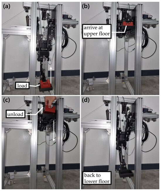
Figure 12.
Procedure of one cycle driving experiment: (a) Ascending with load, (b) Arrival at target position, (c) Load removal, (d) Descending without load.
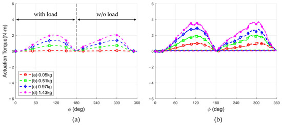
Figure 13.
Driving torque for the optimal load at each movable pulley position: (a) Theoretical, (b) Measured.
Table 3.
Maximum driving torque for the optimal load at each pulley position.
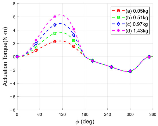
Figure 14.
Driving torque simulation for the optimal load without gravity compensation.
Table 4.
Comparison of the mechanical work calculated from the areas under the torque curves obtained in experimental measurements and simulation.
4.3. Gear Transmission Torque
Simultaneously with the driving torque measurement experiment, the torque variation between the gears was also measured. To achieve this, as shown in Figure 15, a load cell was attached to an extended link connected to the gear. When the lower gear exerts force on the upper gear, the load cell measures this force. The measured force is then converted into torque by multiplying it by the length of the extended link, d. Since the converted torque has the same magnitude but the opposite direction as , the measured value is multiplied by (−1) to correct the sign. During one complete cycle of operation, as illustrated in Figure 11, the force transmitted through the gears was recorded, and the results are presented in Figure 16. The maximum torque values for each condition are summarized in Table 5.
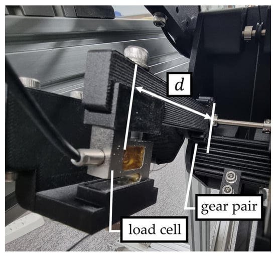
Figure 15.
Experiment setup to measure the transmission torque on the gear: A load cell is installed between the rotating link and the gear.
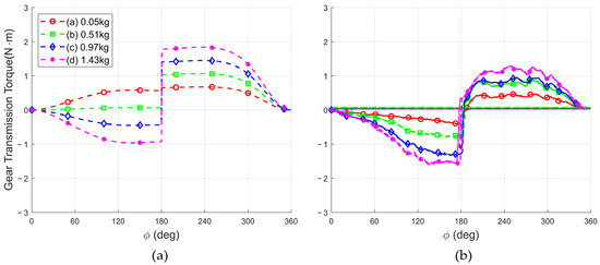
Figure 16.
Gear transmission torque for the optimal load at each movable pulley position: (a) Theoretical, (b) Measured.
Table 5.
Maximum gear transmission torque for the optimal load at each pulley position.
4.4. Accuracy of the Load Platform Position
Simultaneously with the two aforementioned experiments, the positioning error of the lower rotating link was measured. The positioning error caused by the deflection of the lower rotating link directly influences both the driving torque and the torque transmitted through the gears; therefore, it was essential to quantify this error. Additionally, it serves as a supplementary indicator for evaluating the stability of the link connections.
To measure this, a rotary encoder was attached to the lower rotating link, as shown in Figure 17. The encoder used was the AN25-Analog model from Dream Solution Co., Ltd. (Ansan, Republic of Korea), featuring a resolution of 0.0879° (4096 PPR). The angular displacement of the lower rotating link was recorded throughout one full cycle of operation and plotted against the motor angle. The experiments were conducted with a reference load of . Measurements were taken for three cases: when the movable pulley was positioned at the optimal location , when less elastic energy was applied at , and when no gravity compensation was applied. The measured data were then compared with the theoretically simulated values to evaluate the positioning error. The results are presented in Figure 18, and the angular data at the target position, where the motor angle reaches 180°, are summarized in Table 6.
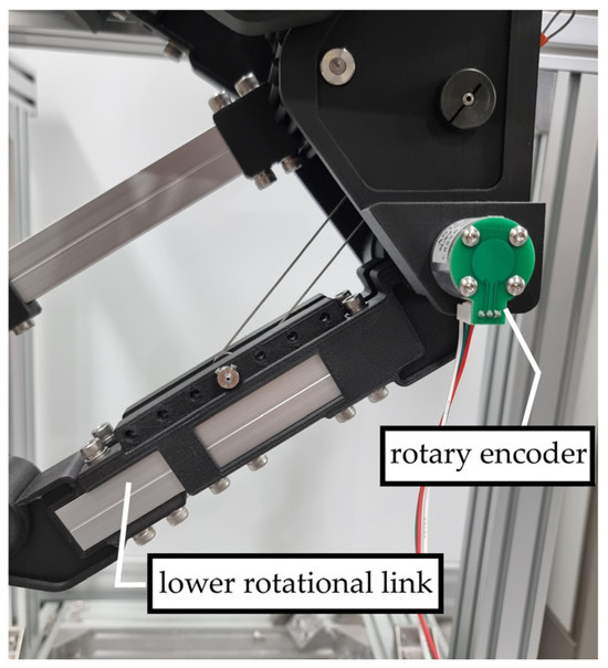
Figure 17.
Experiment setup to measure the positioning error of the distal link. A rotary encoder is installed on the lower rotational link joint.
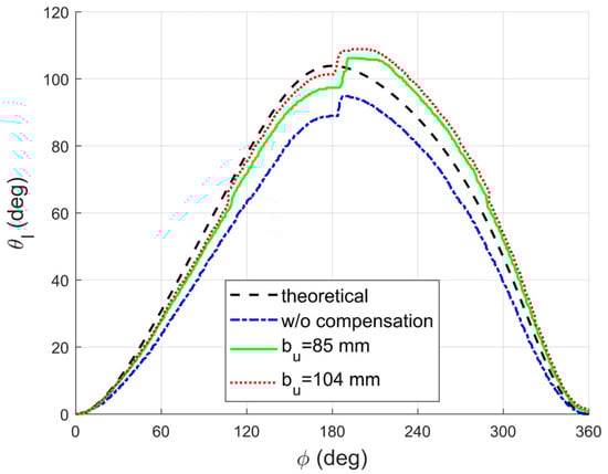
Figure 18.
Measured positioning accuracy with and without compensation.
Table 6.
Angle of the lower rotational link measured at the target point.
5. Discussion
In the preceding Section 4, three experiments were conducted to validate the effectiveness of the proposed mechanism. As observed in the results of the first experiment, which involved measuring the drive torque, the maximum torque during the ascending and descending motions was measured to be nearly identical when the optimal load was applied at each pulley position. Furthermore, the measured torque profiles for the upward and downward motion with and without a load exhibit a symmetric distribution. Given the symmetric nature of the torque profile, the torque values for the downward motion with a load can be inferred from the downward motion without a load by reflecting the torque curve across the x-axis. Thus, the experimental results can effectively represent both loading scenarios within a single graph, confirming the design objective of maintaining consistent torque requirements regardless of the load condition during the ascent or descent phases.
However, the measured torque values were higher than the theoretical predictions due to the gravity compensation mechanism exerting a greater force than intended, necessitating the application of an additional 250 g load for calibration. Moreover, in the static modeling, friction and inertia were neglected; however, in the actual environment, the friction occurring at the joints, along with the internal friction within the cable structure [26], collectively contributed to the increased torque requirement compared to the theoretical values. Furthermore, from Table 4, the effectiveness of the gravity compensation mechanism can be observed from an energy perspective. The results without gravity compensation are derived from simulation data, and in actual measurements, the energy consumption is expected to be higher due to factors such as friction and material deformation. Therefore, the actual reduction in energy consumption when applying gravity compensation is likely to be even more significant than indicated in the table. As shown in the results of (d), the application of gravity compensation reduces the energy consumption by at least 18%, demonstrating a substantial improvement.
Next, in the results of the second experiment, similar to the previously discussed drive torque measurement results, the graph is observed to shift downward during the ascent phase due to the additional 250 g load applied for gravity compensation calibration. This shift indicates that the measured gear transmission torque values are higher than the theoretical predictions as a result of the calibration load. Nonetheless, in all cases, the transmitted torque remained lower than the theoretical values, confirming that the transmitted torque remained within the designed allowable range.
Lastly, as observed in the results of the third experiment, the positioning error improved progressively from 14.35% without gravity compensation to 6.27% when , and further to 2.4% when . These results experimentally confirm that applying appropriate gravity compensation not only enhances the mechanical stability but also improves the overall mechanical reliability of the system. Therefore, from both an energy efficiency perspective and a mechanical reliability standpoint, implementing optimal gravity compensation is a rational approach. Meanwhile, a noticeable jump in the measured values can be observed when the load is removed at . This phenomenon is likely due to a combination of insufficient stiffness in the prototype components, which were fabricated using 3D-printed materials rather than rigid metal structures, and the backlash in the gear mechanism. It is anticipated that this issue could be significantly mitigated by constructing the mechanism with metal components to enhance structural stiffness.
6. Conclusions
For the scale of inter-floor material transport, conventional solutions such as cranes and elevators exhibit low energy efficiency and limited continuity in material transfer, making them less suitable for such applications. Therefore, there is a need to introduce mechanisms that provide higher energy efficiency and repetitive transport capabilities in smaller-scale operations. In this study, a lifting robot was proposed to automate the repetitive and high-intensity task of transporting materials from the lower floor to the upper floor in construction sites, reducing the burden on workers. Additionally, a variable gravity compensation mechanism was introduced to enhance the robot’s energy efficiency, structural stability, and safety under various load conditions. The proposed lifting robot was designed as a 1-DOF system by integrating a gear-connected double parallelogram linkage with a crank-rocker mechanism. This configuration allowed stable and precise bidirectional material transport to the target position using only unidirectional rotational motion of the actuator. Through this structural design, the control burden was significantly reduced, making the robot highly suitable for repetitive tasks.
Furthermore, a gravity compensation mechanism utilizing springs and cables was implemented to simultaneously compensate for gravitational torque at two key joints. As a result, positioning errors of the lower rotating link were significantly reduced, the transmitted torque through the gears decreased, and the overall structural stability of the robot improved. Additionally, this design minimized the robot’s width while reducing the required actuator capacity to less than half, thereby lowering the overall cost of the robot.
Moreover, an adjustable pulley positioning mechanism was incorporated, enabling appropriate tuning of gravity compensation. This system allows for the efficient handling of materials of various weights, particularly in highly repetitive tasks, optimizing energy consumption. In practice, the mechanism for adjusting the pulley position can be composed of a pair of ball screws synchronized according to the ratio and connected by a constant velocity joint. This configured mechanism enables the automation of movable pulley position adjustment. Furthermore, by comparing the energy required for position adjustment with the energy consumed during operation after adjustment, the improvement in energy efficiency can be verified.
While the current study primarily focuses on validating the mechanical functionality and gravity compensation performance of the proposed mechanism, a finite element analysis (FEA) will be considered in future work to assess potential structural deformation under maximum load conditions. This analysis will provide additional insights into optimizing structural stiffness and enhancing positional accuracy under heavy loading scenarios.
Although the current configuration primarily functions as a single-DOF lifting device, the potential for integrating an additional actuator for pulley adjustment would effectively provide a second degree of freedom, enabling adaptive and autonomous control. Furthermore, the proposed mechanism is designed with modularity in mind, allowing for integration with other robotic systems such as autonomous mobile robots (AMRs) or robotic manipulators. This integration capability not only facilitates scalability but also enhances the system’s classification as a robotic module capable of multi-DOF operation in construction and industrial settings.
In conclusion, the proposed lifting robot demonstrates the feasibility of automating inter-floor material transport tasks in construction sites. Further studies on load-handling capacity, system stability, design dimensions, and deployment considerations could enhance its suitability for real-world applications. If further developed and optimized for practical use, this system could be integrated into construction site openings to assist workers in repetitive and labor-intensive material transport tasks, ultimately improving efficiency and safety.
Author Contributions
Conceptualization, B.K. and J.S.; methodology, B.K.; software, B.K.; validation, B.K., S.L. and J.S.; formal analysis, B.K.; investigation, B.K.; resources, B.K.; data curation, B.K.; writing—original draft preparation, B.K.; writing—review and editing, B.K., S.L. and J.S.; visualization, B.K.; supervision, J.S.; project administration, J.S.; funding acquisition, J.S. All authors have read and agreed to the published version of the manuscript.
Funding
This work was supported by the National Research Foundation of Korea (NRF) grant funded by the Korea government under (MSIT) and the BK21 FOUR (Fostering Outstanding Universities for Research) Project in 2025 funded by the Ministry of Education, Department of Robot and Smart System Engineering, Kyungpook National University, Korea (Nos. NRF 2020-R1C1C1008707, 2120240915403).
Data Availability Statement
Dataset available on request from the authors.
Conflicts of Interest
The authors declare no conflicts of interest.
References
- Ali, M.M.; Moon, K.S. Advances in Structural Systems for Tall Buildings: Emerging Developments for Contemporary Urban Giants. Buildings 2018, 8, 104. [Google Scholar] [CrossRef]
- Dai, L.; Liao, B. Innovative High Efficient Construction Technologies in Super High Rise Steel Structure Buildings. Int. J. High-Rise Build. 2014, 3, 205–214. [Google Scholar]
- Kowalczyk, T.; Kozłowski, A. Technological Advances and Trends in Modern High-Rise Buildings. Buildings 2019, 9, 193. [Google Scholar] [CrossRef]
- Schneider, S.P. Musculoskeletal Injuries in Construction: A Review of the Literature. Appl. Occup. Environ. Hyg. 2001, 16, 1056–1064. [Google Scholar] [CrossRef]
- Fung, I.W.H.; Tam, V.W.Y.; Tam, C.M.; Wang, K. Frequency and Continuity of Work-Related Musculoskeletal Symptoms for Construction Workers. J. Civ. Eng. Manag. 2008, 14, 183–187. [Google Scholar] [CrossRef]
- Korea Institute of Labor Safety and Health. Construction Site Main Floor Labor Intensity Evaluation Project (in Korean). Korea Institute of Labor Safety and Health Website. 2020. Available online: https://kilsh.or.kr/2829/ (accessed on 20 May 2025).
- Shapira, A.; Lucko, G.; Schexnayder, C.J. Cranes for Building Construction Projects. J. Constr. Eng. Manag. 2007, 133, 690–700. [Google Scholar] [CrossRef]
- Wu, K.; García de Soto, B. Spatio-Temporal Optimization of Construction Elevator Planning in High-Rise Building Projects. Dev. Built Environ. 2024, 17, 100328. [Google Scholar] [CrossRef]
- Zhang, F.; Zhang, C.; Fu, Y.; Liu, J.; Bu, J.; Duan, P.; Chen, S. A Parameterized Model for Tower Crane Energy Consumption Based on Theoretical Formulation and Field Data. Sci. Rep. 2025, 15, 10453. [Google Scholar] [CrossRef]
- Tuci, E.; Alkilabi, M.H.M.; Akanyeti, O. Cooperative Object Transport in Multi-Robot Systems: A Review of the State-of-the-Art. Front. Robot. AI 2018, 5, 59. [Google Scholar] [CrossRef]
- Gharbia, M.; Chang-Richards, A.; Lu, Y.; Zhong, R.Y.; Li, H. Robotic Technologies for On-Site Building Construction: A Systematic Review. J. Build. Eng. 2020, 32, 101584. [Google Scholar] [CrossRef]
- Wijayathunga, L.; Rassau, A.; Chai, D. Challenges and Solutions for Autonomous Ground Robot Scene Understanding and Navigation in Unstructured Outdoor Environments: A Review. Appl. Sci. 2023, 13, 9877. [Google Scholar] [CrossRef]
- Yang, G.; Wang, S.; Okamura, H.; Shen, B.; Ueda, Y.; Yasui, T.; Yamada, T.; Miyazawa, Y.; Yoshida, S.; Inada, Y.; et al. Hallway Exploration-Inspired Guidance: Applications in Autonomous Material Transportation in Construction Sites. Autom. Constr. 2021, 128, 103758. [Google Scholar] [CrossRef]
- Wu, M.; Yeong, C.F.; Su, E.L.M.; Holderbaum, W.; Yang, C. A Review on Energy Efficiency in Autonomous Mobile Robots. Robot. Intell. Autom. 2023, 43, 648–668. [Google Scholar] [CrossRef]
- Fragapane, G.; De Koster, R.; Sgarbossa, F.; Strandhagen, J.O. Planning and Control of Autonomous Mobile Robots for Intralogistics: Literature Review and Research Agenda. Eur. J. Oper. Res. 2021, 294, 405–426. [Google Scholar] [CrossRef]
- Han, X.S.; Tian, Q. Kinematics Analysis of Palletizing Robot. Adv. Mater. Res. 2014, 915–916, 477–481. [Google Scholar] [CrossRef]
- Said, H.; El-Rayes, K. Optimizing Material Procurement and Storage on Construction Sites. J. Constr. Eng. Manag. 2011, 137, 421–431. [Google Scholar] [CrossRef]
- Lun, M.; Leu, Y. Design of Crank-Rocker Mechanisms with Optimum Transmission Angle over Working Stroke. Mech. Mach. Theory 1996, 31, 501–511. [Google Scholar] [CrossRef]
- Suh, J.W.; Choi, E.C. Design and Verification of a Gravity-Compensated Tool Handler for Supporting an Automatic Hair-Implanting Device. IEEE Robot. Autom. Lett. 2019, 4, 4410–4417. [Google Scholar] [CrossRef]
- Lee, D.; Seo, T. Lightweight Multi-DOF Manipulator with Wire-Driven Gravity Compensation Mechanism. IEEE/ASME Trans. Mechatron. 2017, 22, 1308–1314. [Google Scholar] [CrossRef]
- Deepak, S.R.; Ananthasuresh, G.K. Static Balancing of a Four-Bar Linkage and Its Cognates. Mech. Mach. Theory 2012, 48, 62–80. [Google Scholar] [CrossRef]
- Choi, W.; Suh, J. Design and Evaluation of a Cable-Actuated Palletizing Robot With Geared Rolling Joints. IEEE/ASME Trans. Mechatron. 2024, 29, 3137–3145. [Google Scholar] [CrossRef]
- Nguyen, V.L. Design of a Compact Gear-Spring Mechanism for Static Balancing of Variable Payloads. J. Mech. Des. 2022, 144, 123301. [Google Scholar] [CrossRef]
- Wu, J.; Xin, G.; Qi, C.; Xue, Y. Learning Robust and Agile Legged Locomotion Using Adversarial Motion Priors. IEEE Robot. Autom. Lett. 2023, 8, 4975–4982. [Google Scholar] [CrossRef]
- Markforged. Composite Materials V5.2. Available online: https://s3.amazonaws.com/mf.product.doc.images/Datasheets/Material+Datasheets/CompositesMaterialDatasheet.pdf (accessed on 20 May 2025).
- Peng, Y.; Huang, K.; Ma, C.; Zhu, Z.; Chang, X.; Lu, H.; Zhang, Q.; Xu, C. Friction and Wear of Multiple Steel Wires in a Wire Rope. Friction 2023, 11, 763–784. [Google Scholar] [CrossRef]
Disclaimer/Publisher’s Note: The statements, opinions and data contained in all publications are solely those of the individual author(s) and contributor(s) and not of MDPI and/or the editor(s). MDPI and/or the editor(s) disclaim responsibility for any injury to people or property resulting from any ideas, methods, instructions or products referred to in the content. |
© 2025 by the authors. Licensee MDPI, Basel, Switzerland. This article is an open access article distributed under the terms and conditions of the Creative Commons Attribution (CC BY) license (https://creativecommons.org/licenses/by/4.0/).