
Human-Centric Robotic Solution for Motor and Gearbox Assembly: An Industry 5.0 Pilot Study

 , , , , ,
  and
and 
Abstract

1. Introduction
2. Related Work
3. Proposed Approach
- During the assembly of the engine, it is necessary to manipulate several heavy parts, such as the gearbox, where operators make use of weightless manipulators or cranes to load the parts and attach them to the engine body.
- The engine is transported along the assembly line through the different stations where operators carry out the different assembly steps. Although the majority of the assembly tasks are performed in a stationary way, some of the actions are conducted in movement while the engine is being transported between stations.
- Despite some of the production steps being fully automated, especially those related to the engine body fabrication and machining, many assembly phases involving manipulating small parts are still manual. Therefore, there is a clear separation between robots and operators along the assembly line. This lack of collaboration between robots and humans is also common in the automotive industry.
- Creation of a collaborative environment where industrial robots and operators cooperate in a safe and fenceless environment following the current safety standards.
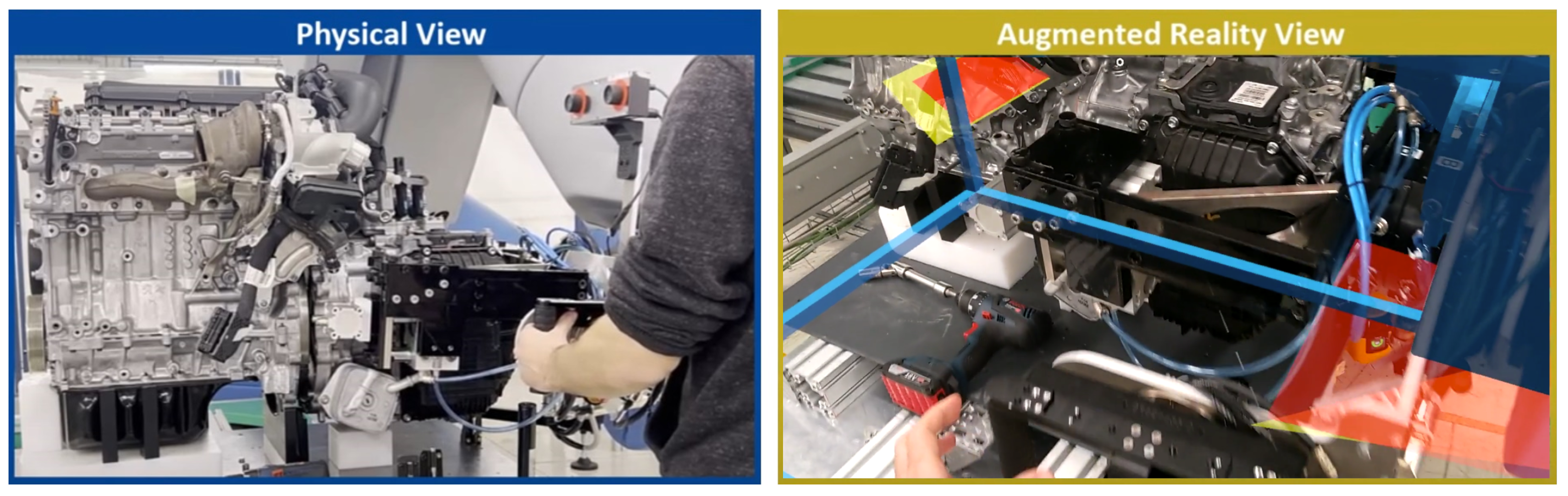
- Enhanced operator capabilities to interact with the robotic cell and receive real-time feedback on the assembly line status through the use of wearable devices, augmented reality, and digital twins.
- Capability to automate different operations around the production line as well as on moving parts employing mobile manipulators to provide flexibility to the manufacturing process.
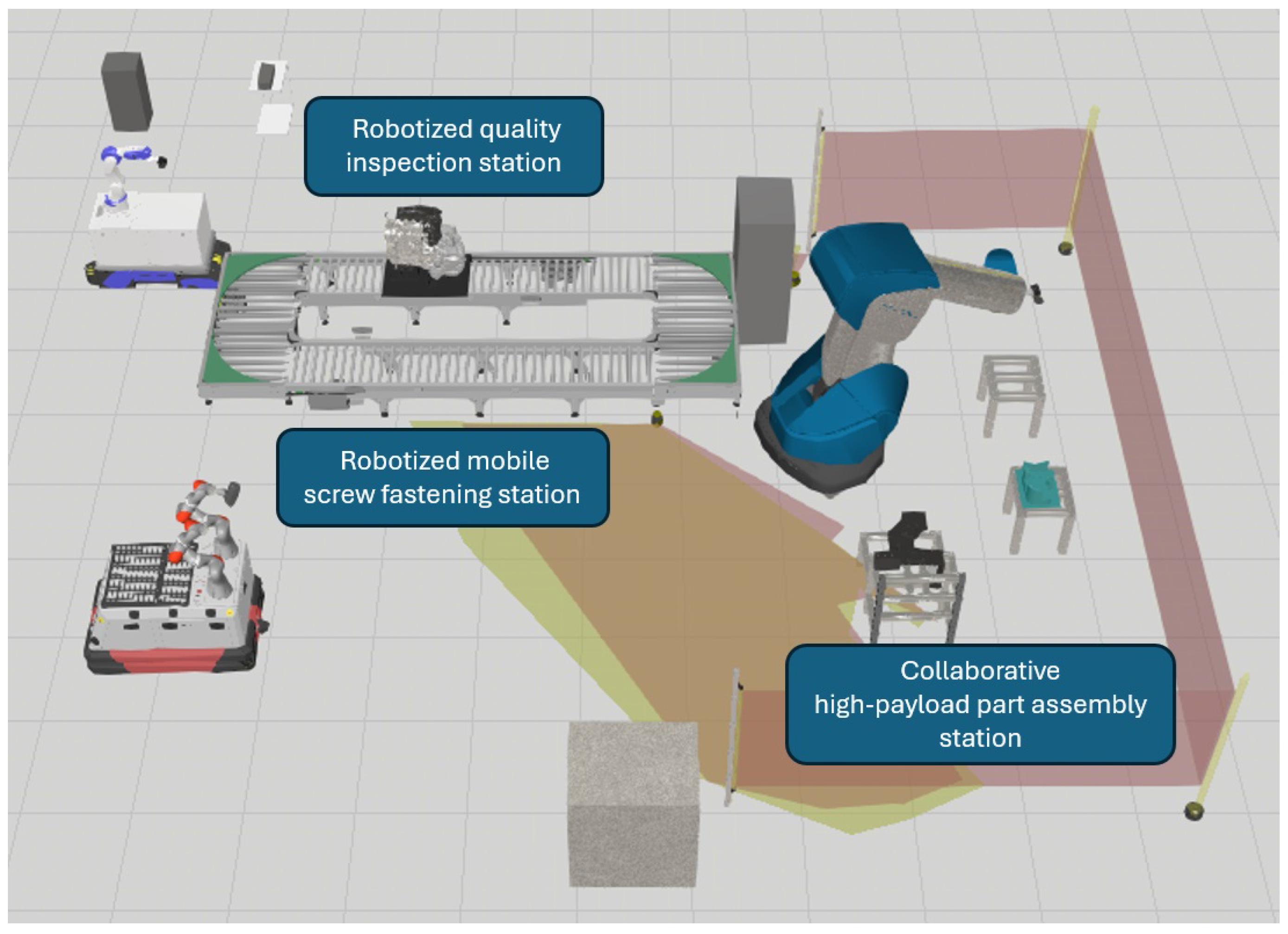
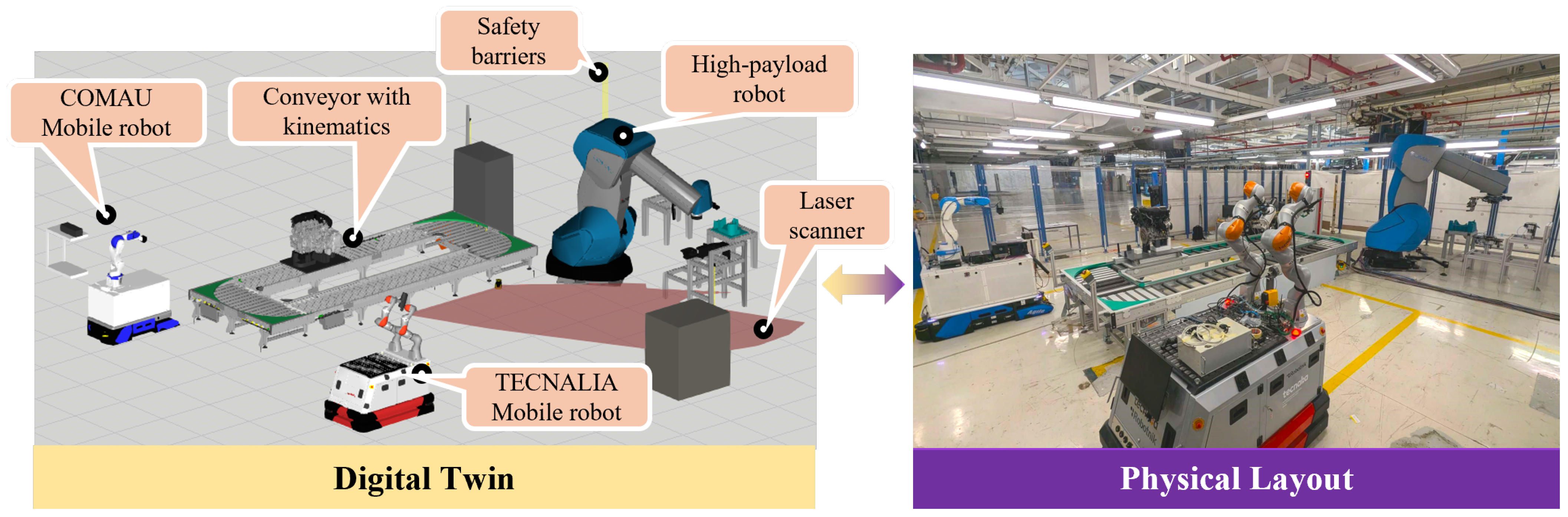
Robotic Cell Layout
- The collaborative high-payload part assembly station where operators interact with a high-payload industrial robot to handle a gearbox and connect it to the main engine body. Additionally, operators place the engine cover on the top part, positioning the bolts that link it to the main body.
- The robotized mobile screw fastening station delivers the engine to the next assembly area, leveraging this transportation time to fasten the screws of the engine cover. The main purpose of the station is to exploit idle transportation time to carry out operations on the engine while it is moving, applying the capabilities of mobile manipulators to fasten the engine cover screws during the conveyance and saving a stationary assembly station on the line.
- The robotized quality inspection station verifies the state of the previous assembly steps using artificial vision. The station takes advantage of the use of mobile manipulators to add flexibility due to the high degree of mobility of the robotic platform, allowing the verification of multiple engine elements and even parts of the same station.
4. Assembly Stations
4.1. Collaborative High-Payload Part Assembly
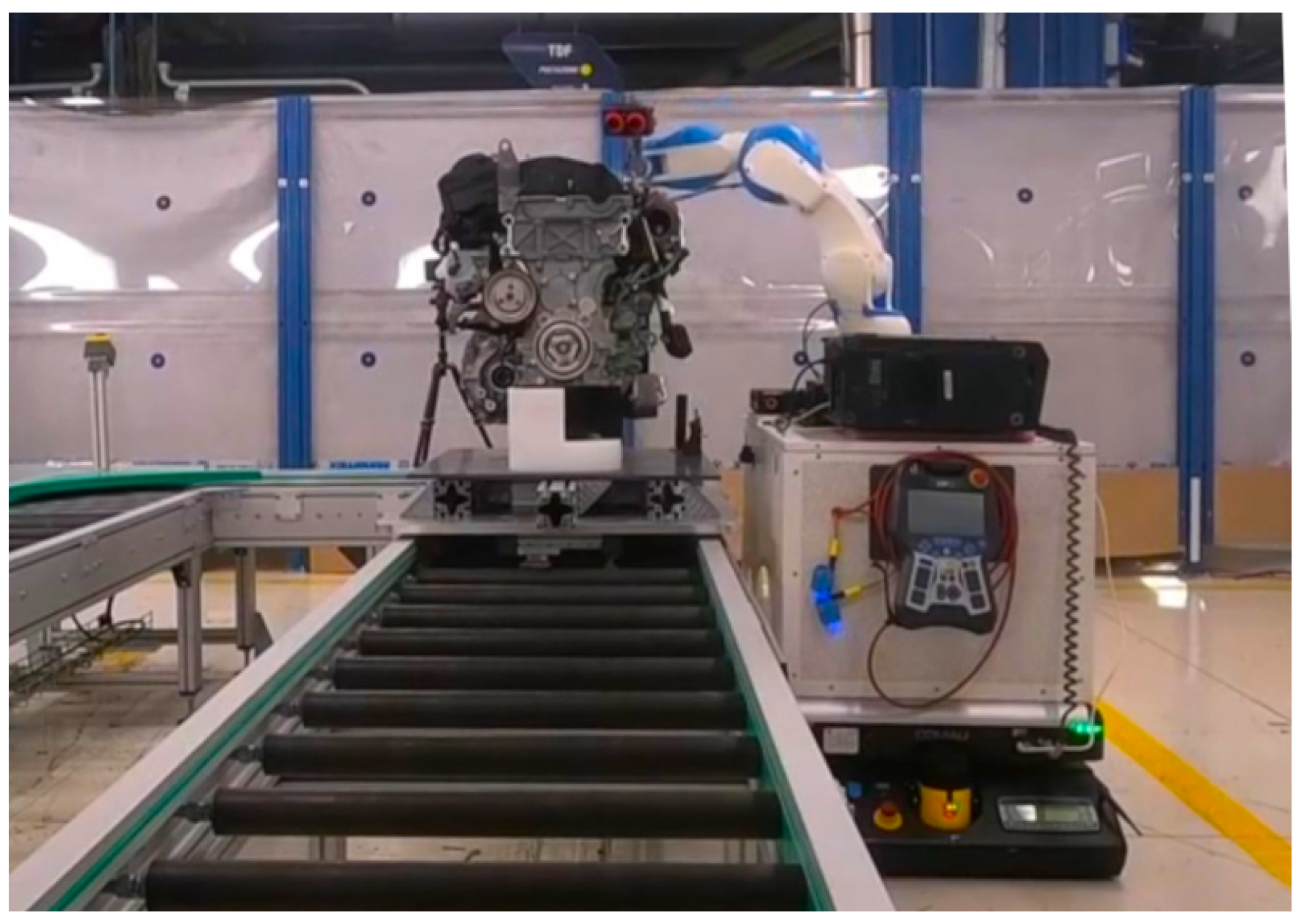
4.2. Robotized Mobile Screw Fastening
4.3. Robotized Quality Inspection
5. Safety Implementation
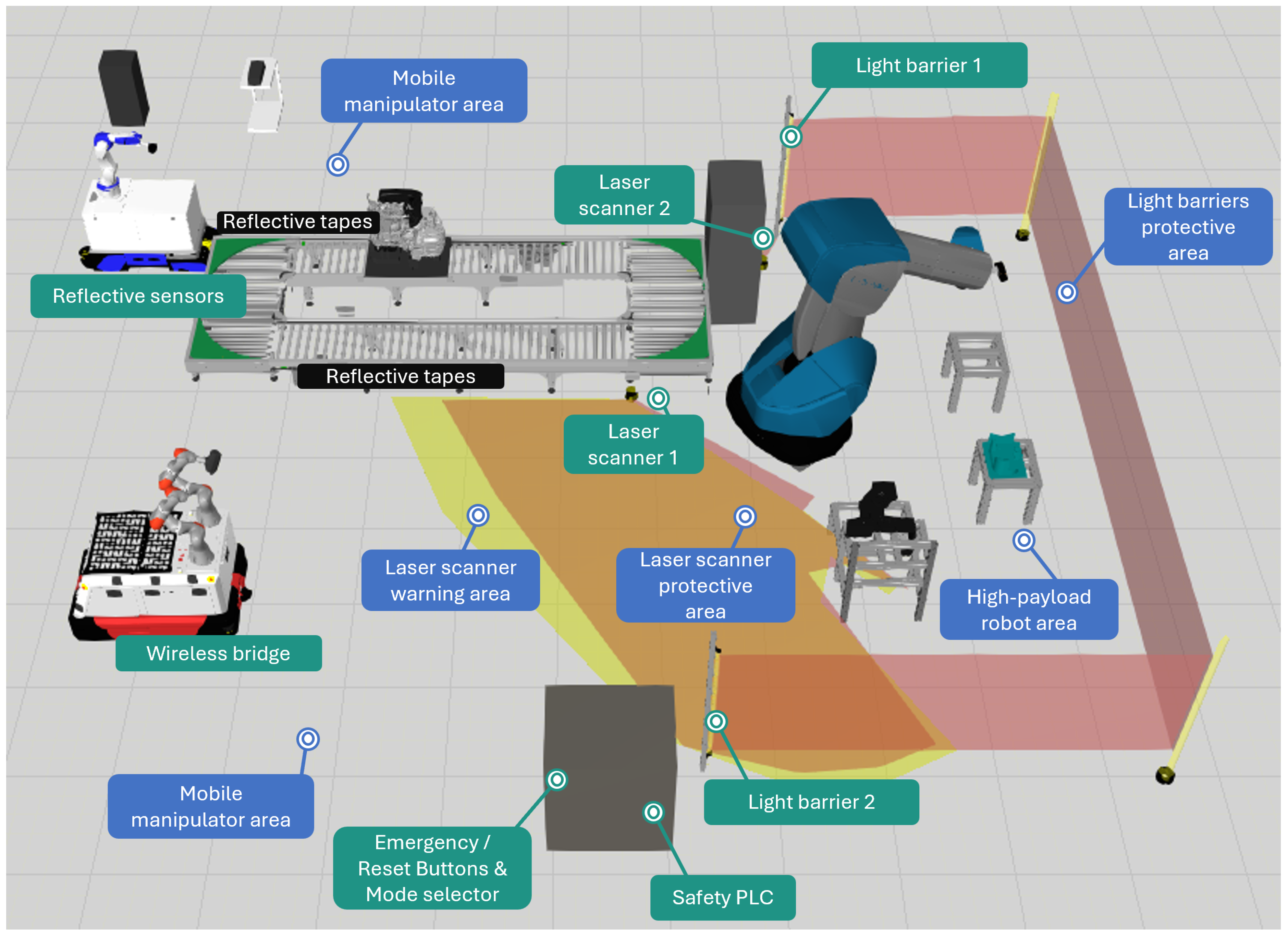
- Programmable Logic Controller (PLC): The safety PLC is the central element of the safety system and it is fully integrated with all safety hardware devices within the robotic cell as well as all the robotic resources and conveyor. The main safety logic is implemented within this PLC to enhance performance and ensure the reliable and consistent operation of the process.
- Light barriers: The safety concept of the high-payload robot area is designed around the installation of one safety light barrier (Figure 10a), complemented by two strategically placed mirrors to ensure comprehensive coverage of the high-payload robot’s operational perimeter. The placement of the light barrier and mirrors is determined by the safety formula based on EN ISO 13855 [31]. The safety light barrier are capable of detecting the presence of human operators and automatically stopping the assembly process if an operator enters the detection zone, ensuring a safe human-robot collaboration environment.
- Emergency and reset buttons: After analysing the layout of the robotic cell as well as the human and robotic tasks towards motor and gearbox parts’ assembly, six emergency stop buttons (Figure 10b) and one reset button have been installed within the cell layout. The emergency buttons stop the assembly process whenever operators perceive any emergency situation. On the contrary, the reset button enables operators to resume the assembly process after any emergency stop, safely resuming the process by pushing the button. All these buttons are integrated with the safety PLC of the robotic cell to ensure immediate response in case of an emergency event.
- Laser scanners: Two laser scanner devices (Figure 10c) have been strategically placed within the robotic cell layout to monitor the presence of human operators and automatically stop the assembly process in case an operator enters the high-payload robot area. The installation of these laser scanners allows the system to reduce the high-payload robot’s speed when obstacles are detected within the warning area. Additionally, three distinct zone configurations have been defined for each laser scanner, with the specific zones adapted to the position of the high-payload robot’s base joint.
- Wireless safe bridge: Although the mobile manipulators include their own security system, it is mandatory to connect the mobile robot with the main safety system of the cell. The connection of mobile manipulators with the main safety PLC is based on wireless safe bridge devices, specifically the Bridge E wireless Ethernet bridge from R3 Solutions [32] shown in Figure 10d. This device ensures ultra-reliable low-latency data transmission, creating a secure channel to send safety signals to the central PLC system.
- Mode selector: As previously mentioned, the connection between the engine and gearbox is based on the manual alignment of the two parts by a human operator using the manual guidance technologies implemented on the high-payload robot. However, this task is a critical assembly step as it provides full control to human operators over the high-payload robot. A mode selector device has been integrated, see Figure 10e, to ensure that the manual guidance mode will only be used by the trained operators. To this end, operators of the assembly line insert a specific configuration key inside the mode selector device to enable the manual guidance of the robot in a safe and controlled way.
- Retroreflective sensors: A critical safety step in the integration of mobile manipulators in the assembly process is the approach of the manipulators to the conveyor, ensuring undesired collisions between the robot and the transporting device. Therefore, retroreflective sensors have been installed on the mobile platforms to safely validate the approach of the mobile robotic resources with the conveyor, as shown in Figure 10f. Additionally, reflective tape has been installed along the conveyor, enabling the activation of the retroreflective sensors when both elements are close enough. Thus, the retroreflective sensors send a safe signal to the mobile manipulator’s safety PLC to adapt the safety zones and enable the manipulator’s movements.
6. Digital Twin
7. Implementation
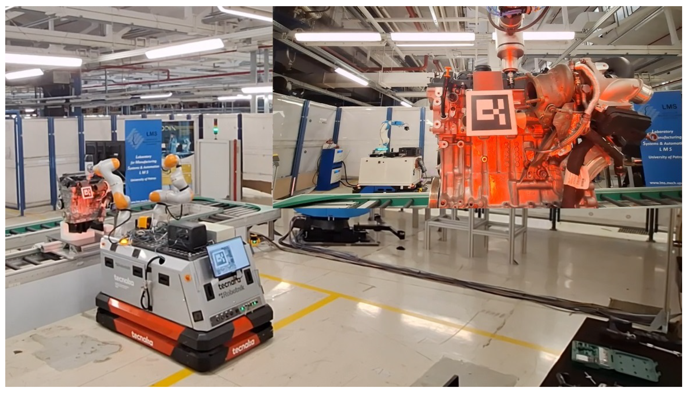
- In the initial collaborative high-payload part assembly station, see Figure 12, an operator assisted by a Comau Aura collaborative industrial robot fixes the gearbox to the engine body using the hand-guiding device, using augmented reality to interact with the complete robotic system.
- After this initial step, the operator fits the engine cover to the main body by placing several bolts manually. Once the engine cover is in position, the complete engine moves along the mobile screw fastening station where an autonomous mobile manipulator fastens these screws as shown in Figure 13.
- Finally, when the engine reaches the robotized quality inspection station, a second mobile manipulator captures various images to perform the quality inspection and verify the previous steps of the assembly. The operator receives real-time feedback on the quality inspection, see Figure 14, as well as corrective measures whenever the quality system detects incorrectly assembled elements.
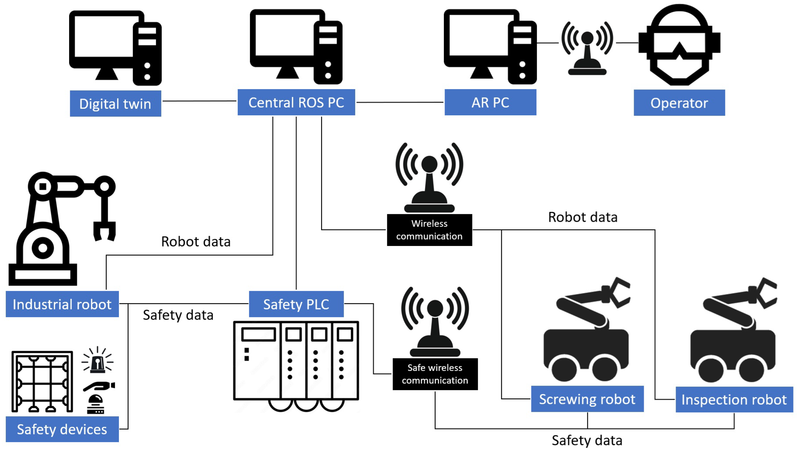
- The central element is the central ROS PC, which manages all the robot and safety information and triggers the different robot actions. It also distributes all required information to the digital twin PC and interacts with the operator through the AR PC.
- The Safety PLC gathers all safety information from the safety devices, industrial robot, and mobile manipulators. After processing this safety information, the processed information is sent to the central ROS PC.
- The digital twin PC receives the cell status information from the central ROS PC, storing it and digitally representing the state of the whole cell.
- The AR PC receives the high-level operator interaction commands from the AR hardware, processing the information and sending it to the central ROS PC. Afterwards, the system feedback is presented to the operator through the AR hardware.
8. Validation
8.1. Collaborative High-Payload Part Assembly
- Added value of AR-based application during the execution of the assembly process: The first question focuses on the added value of the developed AR-based application on this initial station. 33 out of the 37 workers thought it was very profitable for them during the execution of the gearbox assembly process as it offered a detailed visualization of how to perform the required tasks with a user-friendly interface. 3 operators were neutral about the added value of the AR application, while 1 of them categorized the application as a non-added value technology.
- Complexity of AR-based application for assembly line’s operators: The second question focuses on the complexity of the AR application for the operators. 30 out of 37 operators described the AR-based application as "easy to use" during the axle alignment tasks. According to the collected feedback, the assembly instructions for the operators were very clear and presented very precisely to the operators through the virtual world of the AR application. 5 operators were neutral about the complexity of the application. Only 2 operators stated that the developed solution was difficult to use due to the high brightness and the contrast of the objects included in the virtual world of the AR application.
- Functionality of hand guidance technology: During the tests, operators were able to interact with the high-payload robot through its manual guidance functionality without any calibration procedure required. Out of 37 operators who tested the technology, 34 of them were very surprised about the smoothness of the robotic movements and how easy it was for them to align the engine and gearbox parts with minimum forces applied to the manual guidance joystick installed on the robotic gripper. 2 operators were neutral about the functionality while 1 operator described the developed application as difficult to use due to the high sensitivity of the guidance sensor.
8.2. Mobile Screw Fastening
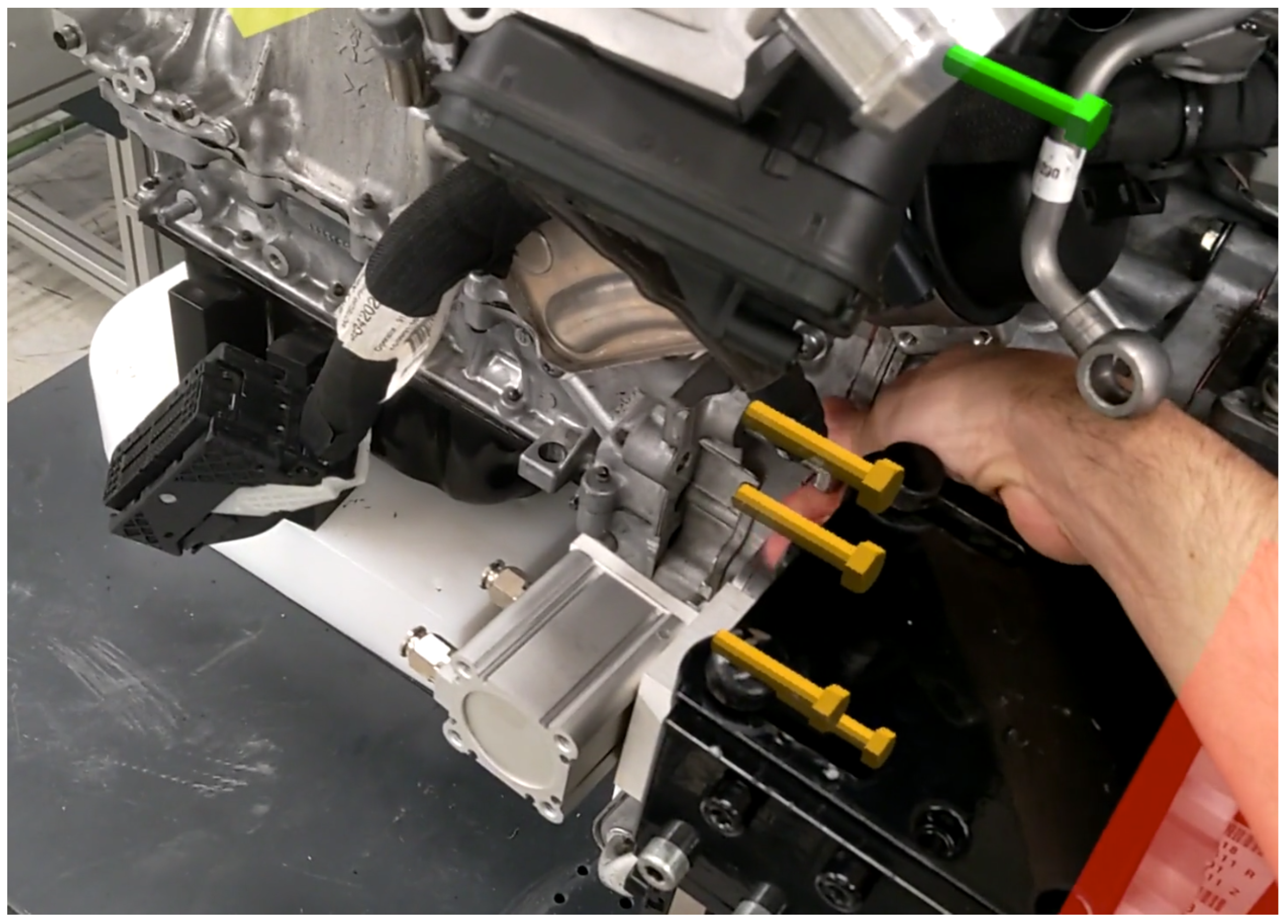
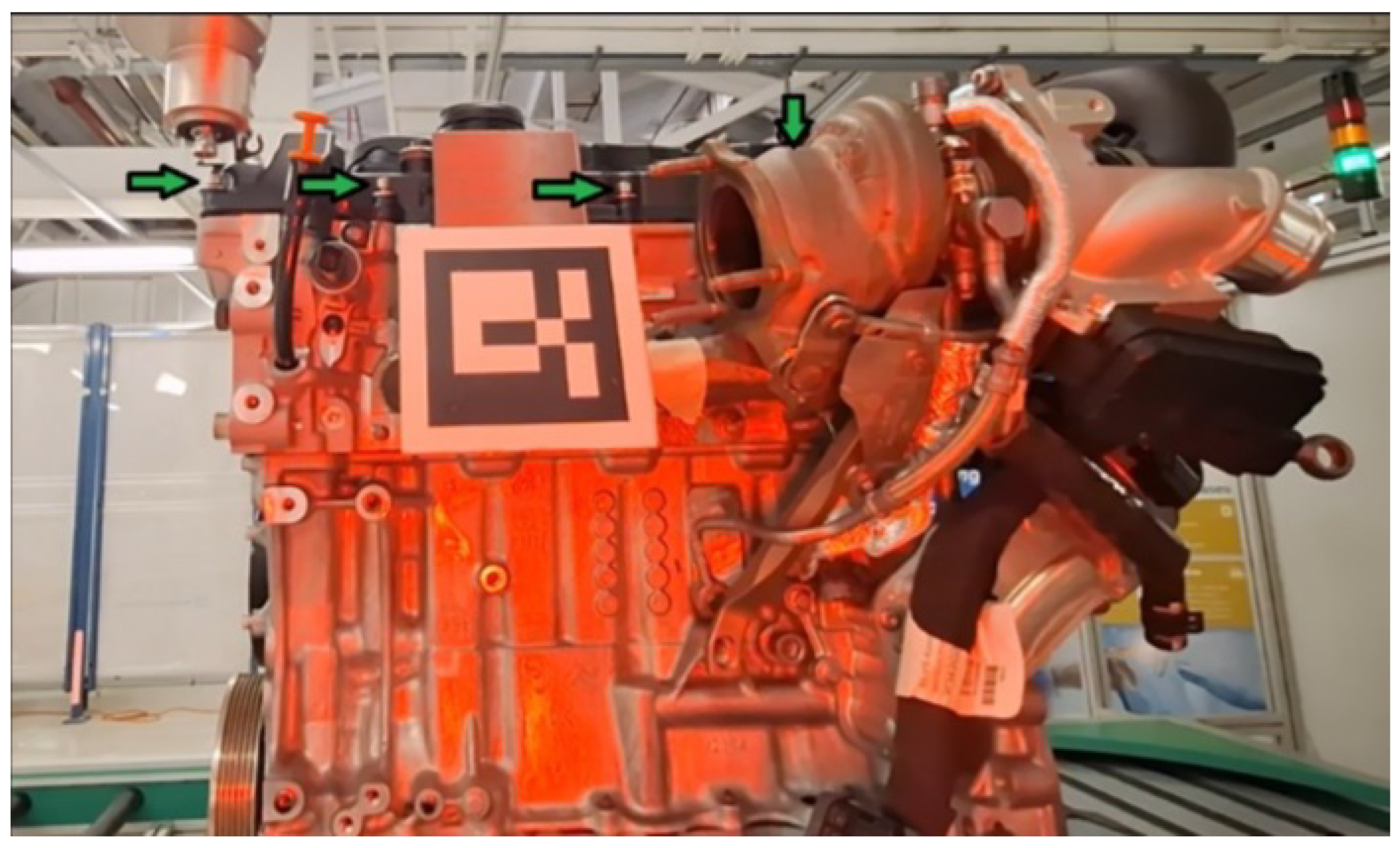
- The engine was placed on the conveyor belt, with 4 different bolts accessible for the robot, as shown in Figure 17.
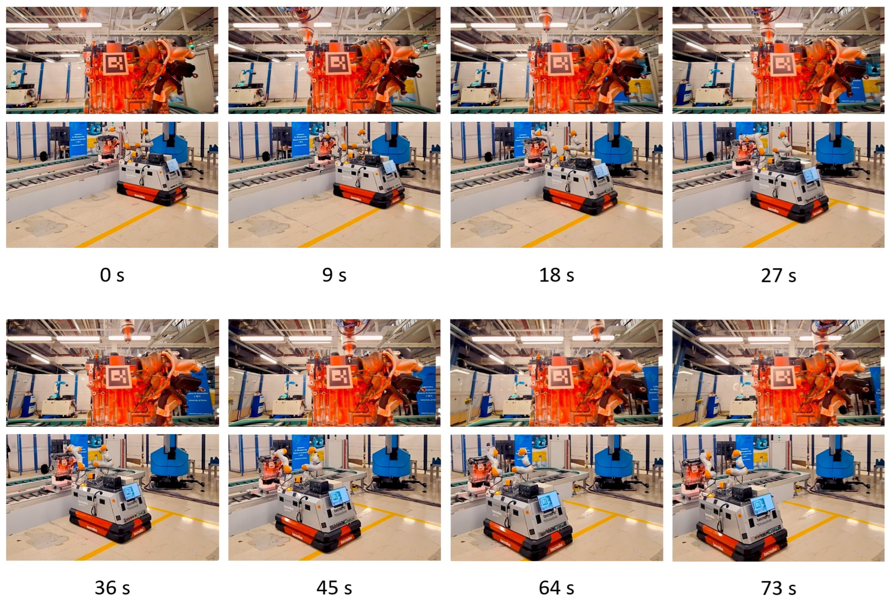
- The engine is transported at a speed of 100 mm/s, starting the movement when the mobile manipulator triggers the “start” signal when the gearbox assembly area is reached.
- Due to the positioning error of the laser-based navigation system of the mobile platform, the initial relative position between the engine and robot has a variability of up to 10 cm and 5º. Therefore, the engine was not always visible to the robot. In these cases, the start signal was triggered and the robot waited until the engine appeared on the field of view of the camera.
- The screw fastening operation was repeated 25 times, including navigation to the initial screwing positions, screw fastening operation, and navigation back to the robot station area. Therefore, 100 screws were fastened in these 25 rounds.
- 90 of the 100 screws were correctly fastened, obtaining a 90% of success rate. In all the failures, the screw was fastened to some degree although the process stopped due to some oscillations between the robot and engine.
- The mean screw fastening time (per screw) was 8.79 s with a standard deviation of 0.43 s. On average, 4.51 s were spent approaching the screws and 4.28 s fastening once the screwdriver was correctly positioned.
8.3. Robotized Quality Inspection
9. Conclusions and Future Work
Author Contributions
Funding
Data Availability Statement
Conflicts of Interest
References
- Misiti, A. A History of Industrial Robots. 2020. Available online: https://www.wevolver.com/article/a-history-of-industrial-robots (accessed on 23 April 2025).
- IFR. One Million Robots Work in Car Industry Worldwide. 2023. Available online: https://ifr.org/ifr-press-releases/news/one-million-robots-work-in-car-industry-worldwide-new-record (accessed on 23 April 2025).
- Schwab, K. The Fourth Industrial Revolution; Crown Publishing Group: New York, NY, USA, 2017. [Google Scholar]
- Breque, M.; De Nul, L.; Petridis, A. Industry 5.0—Towards a Sustainable, Human-Centric and Resilient European Industry; European Commission, Directorate-General for Research and Innovation: Gasperich, Luxembourg, 2021. [Google Scholar]
- Zafar, M.H.; Langås, E.F.; Sanfilippo, F. Exploring the synergies between collaborative robotics, digital twins, augmentation, and industry 5.0 for smart manufacturing: A state-of-the-art review. Robot. Comput.-Integr. Manuf. 2024, 89, 102769. [Google Scholar] [CrossRef]
- Doyle-Kent, M. Collaborative Robotics in Industry 5.0. Ph.D. Thesis, Technische Universität Wien, Wien, Austria, 2021. [Google Scholar]
- Rahman, M.M.; Khatun, F.; Jahan, I.; Devnath, R.; Bhuiyan, M.A.A. Cobotics: The Evolving Roles and Prospects of Next-Generation Collaborative Robots in Industry 5.0. J. Robot. 2024, 2024, 2918089. [Google Scholar] [CrossRef]
- Lettera, G.; Natale, C. An Integrated Architecture for Robotic Assembly and Inspection of a Composite Fuselage Panel with an Industry 5.0 Perspective. Machines 2024, 12, 103. [Google Scholar] [CrossRef]
- Mincă, E.; Filipescu, A.; Cernega, D.; Șolea, R.; Filipescu, A.; Ionescu, D.; Simion, G. Digital Twin for a Multifunctional Technology of Flexible Assembly on a Mechatronics Line with Integrated Robotic Systems and Mobile Visual Sensor—Challenges towards Industry 5.0. Sensors 2022, 22, 8153. [Google Scholar] [CrossRef] [PubMed]
- Land, N. Towards Implementing Collaborative Robots Within the Automotive Industry. 2018. Available online: https://his.diva-portal.org/smash/get/diva2:1230951/FULLTEXT01.pdf (accessed on 23 April 2025).
- Gopinath, V.; Johansen, K.; Gustafsson, Å.; Axelsson, S. Collaborative Assembly on a Continuously Moving Line—An Automotive Case Study. Procedia Manuf. 2018, 17, 985–992. [Google Scholar] [CrossRef]
- Heydaryan, S.; Suaza Bedolla, J.; Belingardi, G. Safety design and development of a human-robot collaboration assembly process in the automotive industry. Appl. Sci. 2018, 8, 344. [Google Scholar] [CrossRef]
- Boboc, R.G.; Gîrbacia, F.; Butilă, E.V. The application of augmented reality in the automotive industry: A systematic literature review. Appl. Sci. 2020, 10, 4259. [Google Scholar] [CrossRef]
- Michalos, G.; Kousi, N.; Karagiannis, P.; Gkournelos, C.; Dimoulas, K.; Koukas, S.; Mparis, K.; Papavasileiou, A.; Makris, S. Seamless human robot collaborative assembly—An automotive case study. Mechatronics 2018, 55, 194–211. [Google Scholar] [CrossRef]
- Wulff, L.A.; Schmedemann, O.; Schüppstuhl, T. Use of augmented reality for iterative robot program optimisation in robot-automated series production processes. Procedia Comput. Sci. 2024, 232, 1991–2000. [Google Scholar] [CrossRef]
- Comau AURA. Available online: https://www.comau.com/en/our-offer/robotics-automation/collaborative-robotics/aura-collaborative-robot (accessed on 23 April 2025).
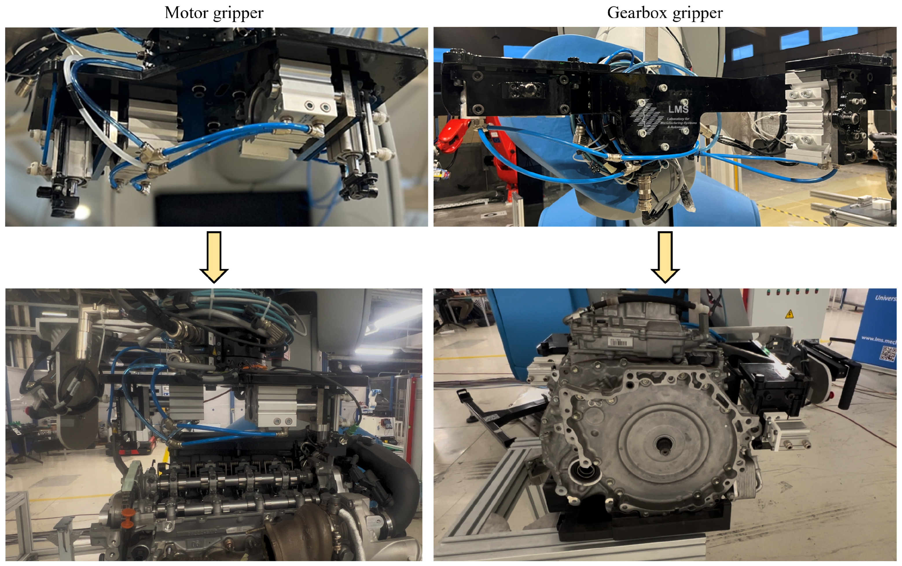
- Papavasileiou, A.; Aivaliotis, S.; Mparis, P.; Mantas, P.; Makris, S. A modular framework of robot gripping tools for human robot collaborative production lines. Procedia CIRP 2024, 126, 164–169. [Google Scholar] [CrossRef]
- Microsoft HoloLens. Available online: https://learn.microsoft.com/es-es/hololens (accessed on 23 April 2025).
- Unity3D. Available online: https://unity.com/ (accessed on 23 April 2025).
- Mixed Reality Toolkit. Available online: https://github.com/microsoft/MixedRealityToolkit (accessed on 23 April 2025).
- ROS#. Available online: https://github.com/siemens/ros-sharp (accessed on 23 April 2025).
- Gfrerrer, A. Geometry and kinematics of the Mecanum wheel. Comput. Aided Geom. Des. 2008, 25, 784–791. [Google Scholar] [CrossRef]
- Kuka LBR Iiwa. Available online: https://www.kuka.com/en-us/products/robotics-systems/industrial-robots/lbr-iiwa (accessed on 23 April 2025).
- IDS. Available online: https://en.ids-imaging.com (accessed on 23 April 2025).
- OnRobot. Available online: https://onrobot.com/en/products/onrobot-screwdriver (accessed on 23 April 2025).
- ROS Navigation Stack. Available online: http://wiki.ros.org/navigation (accessed on 23 April 2025).
- González Huarte, J.; Ibarguren, A. Visual Servoing Architecture of Mobile Manipulators for Precise Industrial Operations on Moving Objects. Robotics 2024, 13, 71. [Google Scholar] [CrossRef]
- Roboception RC Visard. Available online: https://roboception.com/3d-stereo-vision/rc-visard-3d-stereo-sensor (accessed on 23 April 2025).
- Comau Agile 1500. Available online: https://www.comau.com/wp-content/uploads/2021/07/Comau_AGILE1500_Brochure_EN.pdf (accessed on 23 April 2025).
- Comau Racer 5. Available online: https://www.comau.com/en/our-offer/products-and-solutions/robot-team/racer-5-0-80-cobot (accessed on 23 April 2025).
- ISO 13855. Available online: https://www.iso.org/standard/80590.html (accessed on 23 April 2025).
- R3 Solutions Bridge E. Available online: https://www.r3.group (accessed on 23 April 2025).
- ISO 10218-1. Available online: https://www.iso.org/standard/73933.html (accessed on 23 April 2025).
- ISO 10218-2. Available online: https://www.iso.org/standard/73934.html (accessed on 23 April 2025).
- ISO/TS 15066. Available online: https://www.iso.org/standard/62996.html (accessed on 23 April 2025).


Disclaimer/Publisher’s Note: The statements, opinions and data contained in all publications are solely those of the individual author(s) and contributor(s) and not of MDPI and/or the editor(s). MDPI and/or the editor(s) disclaim responsibility for any injury to people or property resulting from any ideas, methods, instructions or products referred to in the content. |
© 2025 by the authors. Licensee MDPI, Basel, Switzerland. This article is an open access article distributed under the terms and conditions of the Creative Commons Attribution (CC BY) license (https://creativecommons.org/licenses/by/4.0/).
Share and Cite
Ibarguren, A.; Aivaliotis, S.; González Huarte, J.; Urquiza, A.; Baris, P.; Papavasileiou, A.; Michalos, G.; Makris, S. Human-Centric Robotic Solution for Motor and Gearbox Assembly: An Industry 5.0 Pilot Study. Robotics 2025, 14, 56. https://doi.org/10.3390/robotics14050056
Ibarguren A, Aivaliotis S, González Huarte J, Urquiza A, Baris P, Papavasileiou A, Michalos G, Makris S. Human-Centric Robotic Solution for Motor and Gearbox Assembly: An Industry 5.0 Pilot Study. Robotics. 2025; 14(5):56. https://doi.org/10.3390/robotics14050056
Chicago/Turabian StyleIbarguren, Aitor, Sotiris Aivaliotis, Javier González Huarte, Arkaitz Urquiza, Panagiotis Baris, Apostolis Papavasileiou, George Michalos, and Sotiris Makris. 2025. "Human-Centric Robotic Solution for Motor and Gearbox Assembly: An Industry 5.0 Pilot Study" Robotics 14, no. 5: 56. https://doi.org/10.3390/robotics14050056
APA StyleIbarguren, A., Aivaliotis, S., González Huarte, J., Urquiza, A., Baris, P., Papavasileiou, A., Michalos, G., & Makris, S. (2025). Human-Centric Robotic Solution for Motor and Gearbox Assembly: An Industry 5.0 Pilot Study. Robotics, 14(5), 56. https://doi.org/10.3390/robotics14050056