Review

Analytical Modeling, Virtual Prototyping, and Performance Optimization of Cartesian Robots: A Comprehensive Review

1
Department of Industrial Engineering, University of Padova, Via Venezia, 1, 35131 Padova, Italy
2
Industrial Robotics Facility (InBot), Istituto Italiano di Tecnologia, Via Morego, 30, 16163 Genoa, Italy
*
Author to whom correspondence should be addressed.
Robotics 2025, 14(5), 62; https://doi.org/10.3390/robotics14050062
Submission received: 20 March 2025 / Revised: 23 April 2025 / Accepted: 1 May 2025 / Published: 3 May 2025
(This article belongs to the Special Issue Integrating Robotics into High-Accuracy Industrial Operations)

Abstract

:
A comprehensive literature review on the kinematics and dynamics modeling and virtual prototyping (V.P) of the Cartesian robots with a flexible configuration is presented in this paper. Different modeling approaches of the main components of the Cartesian robot, which includes linear belt drives and structural components, are presented and discussed in this paper. Furthermore, the vibrations modeling, trajectory planning, and control strategies of the Cartesian robot are also presented. The performance optimization of the Cartesian robot is discussed here, which is affected by the highly flexible configuration of the robot incurred due to high-mix, low-volume production. The importance of virtual prototyping techniques, like finite element analysis and multi-body dynamics, for modeling Cartesian robots or its components is presented. Design and performance optimization methods for robots with a flexible configuration are discussed, although their application to Cartesian robots is rare in the literature and it presents an exciting opportunity for future research in this area. This review paper focuses on the importance of further research on the virtual prototyping tools for flexibly configured robots and their integration with experimental validation. The findings offer useful insights to industries looking to maximize their production processes while keeping the customization, reliability, and efficiency.

1. Introduction

Modern industries are shifting from mass production models to more flexible configuration production models with advancements in technology and changing market demands. Modern manufacturing industries are facing a big challenge due to the high variations in customer product demand while maintaining the quality of the product and the performance of the robot [1]. This issue can be resolved through flexibly configured and customizable robotic systems as they are capable of handling high-mix, low-volume (HMLV) production while maintaining the precision and accuracy. There is an increasing demand for flexibly configured Cartesian robots as they offer a balance between adaptability and precision of the robot while working in an HMLV production environment [2].
Today, flexible and reconfigurable systems are replacing rigid mass-producing processes in modern production systems that enable high product customization while keeping the performance and efficiency. One choice for manufacturers is to adopt a flexibly configured Cartesian robot to meet these demands, as it has linear movements and a modular structure making it ideal for a variety of applications. A flexibly configured Cartesian robot is an industrial robot whose design and kinematics can be reconfigured rapidly in order to meet the changing production requirements. The main characteristics of this type of robot are its modular linear axis and adjustable end effectors that can be modified according to production requirements while maintaining its desired performance. In the HMLV production environment, the robot’s flexibility can be very useful, as it can be rapidly customized to adapt to the new application. A Cartesian robot has different configurations based on the type of linear drive used and the end effector. The different types of drives used in Cartesian robots are the belt-and-pulley drive, rack-and-pinion drive, ball-screw drive, and linear motor drive.
The enhanced flexible configuration of Cartesian robots presents new challenges. Developing an improved flexible configuration means variations in the robot workspace, weight distribution, structural stiffness, and other design parameters. These variations affect the kinematics and dynamics of the whole robot and the performance is affected. Therefore, in order to achieve optimal performance, it is mandatory to carefully analyze all the design parameters. The analysis of the design parameters is a difficult job if it is performed analytically. However, the application of advanced modeling and simulation tools for the design and performance optimization of flexibly configured robots becomes important with the increase in demands for better repeatability and accuracy.
Virtual prototyping has emerged as one of the important techniques for the design and modeling of such customizable robotic systems. A complete robot model can be developed using virtual prototyping tools while applying different design constraints and operating conditions and then analyzing the response of the virtual model [3,4]. This technique involves creating simulation models of the actual machine in order to test and validate the design concept of the prototype and enhance its performance before physical prototyping. V.P is useful in the design and development stage of the machines. This is an emerging research field and is being widely used in many commercial applications. V.P techniques include CAD/CAM, multi-body simulations (MBSs), finite element analysis (FEA), and other computational tools that designers can use to analyze different aspects, such as dynamic performance, structural integrity, and vibration characteristics. These simulation techniques help optimize robot design and performance while reducing development time and cost. The design can be optimized using the design of experiments (DOE) method in which the V.P model is simulated iteratively by changing different design variables while satisfying constraint functions and achieving an objective function. After these simulations, an optimum design of a robot is selected while improving the performance of the robot. The simulation results are experimentally validated using the actual robot before finalizing the design. The use of V.P for improving the flexibility of robots provides a promising research area for future researchers. Virtual prototyping can be upgraded to the development of digital twins, where the virtual model and physical robot are integrated together in real time to diagnose the performance.
Cartesian robots provide an ideal platform for precise positioning applications such as CNC, pick-and-place operations, 3D printing, laser cutting, material handling, and assembly operations because of their ability to operate on multiple axes and their rigid motion. Cartesian robots are exceptionally good in these applications because these applications are normally confined to a one-dimensional or single plane. The precision requirements in these applications are very high, which makes Cartesian robots an ideal choice. Cartesian robots are highly adaptable and configurable, making them a perfect choice for these applications because they can be easily scaled according to the requirements. This feature makes them an ideal candidate for flexible production applications. Cartesian robots can also be used with single and dual drives. In the dual drive, a combination of two single Cartesian drives is used to enable a long-stroke axis in between them. These types of drives are used when long-distance transfer and heavy load capacity is desired. The common industries where Cartesian robots are used are pharmaceuticals, packaging, metal, food processing, and manufacturing. From this discussion, it can be concluded that the main advantages of Cartesian robots are their rigid structure, adaptability, precision, and repeatability. They can be rapidly scaled and reconfigured according to the requirements of any application, which make them an ideal candidate for flexible manufacturing applications. The main disadvantage of the Cartesian robot is the requirement of a large space for them to operate. The reconfiguration of these robots in a flexible production environment can lead to a reduction in their performance.
In the past, the kinematics and dynamics of the Cartesian robots and its drives have been analyzed in different research works. These studies are mostly limited to a rigid robot configuration used in specific industrial applications. The virtual prototyping method has also been used for the modeling of Cartesian robots in specific cases. However, the applications of virtual prototyping and analytical modeling are limited for the design and performance optimization of flexibly configured Cartesian robots. The research gap has been identified in this review paper by combining existing methodologies with possible future research opportunities.
The main aim of this review article is to examine the kinematics and dynamics modeling and virtual prototyping techniques that can be used for the design and development of flexibly configured Cartesian robots. The current methods for the modeling of a Cartesian robot and its components are comprehensively analyzed in this paper. These methods include kinematics and dynamics analysis, vibration reduction, trajectory generation, and controls. Furthermore, virtual prototyping methods to develop the models of flexibly configured Cartesian robots are discussed, and the different virtual prototyping techniques such as MBSs and FEA to enhance the design and performance optimization of robots are also analyzed. In addition, the significance of experimental validation is emphasized, which is very important to verify the simulation results and to present a final design for real-world applications.

State of the Art

In the past few years, industrial robots have progressed significantly due to the growing demand for flexible production systems, particularly in cases where high product variety and low production quantities are required. Cartesian robots are leading these advances in flexible manufacturing due to their linear motion and modular structure. The performance of flexibly configured Cartesian robots is improved by continuously optimizing the robot design. Optimization enables them to work in the HMLV production environment without compromising their accuracy and repeatability. In this paper, the state-of-the-art work on the design and optimization of a Cartesian robot and its components is presented, which summarizes the advancements made so far in analytical modeling, virtual prototyping, and performance optimization of the robot.
  • Analytical Modeling: Recent research on Cartesian robots has focused on improving the kinematic and dynamic models of robots to account for flexible configurations and nonlinear elements, such as those in belt–pulley systems. These models provide solutions to challenges such as precision positioning of the drives and vibrations despite different problems, such as configuration flexibility, elasticity, and nonlinear friction of the drives. Advanced analytical modeling strategies can accurately predict robot behavior, which is very important for designing adaptable robotic systems. Vibration reduction strategies for both the structure and linear drive can improve stability and position accuracy of the system. Robust control strategies can efficiently handle the model uncertainties and disturbances, thus enabling precise positioning and reduced chattering. Trajectory planning enhances the performance by ensuring smooth time- and energy-optimal motion trajectories. Analytical models identify the key design parameters, constraints, and optimization goals that are useful for virtual prototype modeling and optimization of a robot.
  • Virtual Prototyping: Nowadays, virtual prototyping is turning out to be an important and irreplaceable means for design optimization of industrial robots. Virtual prototyping can help in simulating both the kinematics and dynamics of a robot to test its different possible configurations, refine influencing design parameters, and predict the output response of the robot without building a physical prototype. With the help of V.P, an optimum design of a Cartesian robot with enhanced performance can be developed. The two main V.P techniques that are discussed here for modeling flexibly configured robots are multi-body dynamics and finite element methods. Multi-body analysis tools perform a detailed analysis of robot movement and its forces and interactions between its components. The assessment of the deformation, structural integrity, and stress distribution of a robot under operational loads is enabled by finite element analysis techniques. The design and performance of the robots can be optimized using these tools by changing different parameters while setting some design constraints and analyzing the output performance. This will help in reducing the time and cost associated with traditional design methods while it will ensure that the robot satisfies the required performance standards. Using virtual prototyping, robot designers can maximize the configuration flexibility, precision, and durability of the robot through repeated simulation and refinement of the robot design in software, especially in applications with HMLV production.
  • Performance Optimization: The main objective of optimization in industrial robotics is to improve the design and performance of a robot through analytical modeling and virtual prototyping strategies. Each strategy addresses specific challenges and proposes solutions to them. Vibration analysis, controller design, and input trajectory modeling can enhance the robot’s overall performance by addressing different problems and proposing its solutions. The design optimization can be performed using virtual prototyping strategies, such as design study, design of experiments, and optimization. The design optimization process using V.P is accomplished by iteratively simulating the V.P of the robot in which single or multiple design variables vary while achieving an objective and satisfying some constraints. By following this thorough approach, robots can be customized to meet specific needs while remaining flexible and reliable.
Figure 1 illustrates the entire design and optimization process that integrates analytical modeling and virtual prototyping. The simulation results help in the optimization, which is followed by a final validation through experimentation or physical prototyping.

2. Modeling of the Cartesian Robots

A Cartesian robot, also called a gantry robot, is a three-axis movement robot that is widely used in many industrial applications. All of its three axes, X, Y, and Z, are rigid in structure and make a right angle with each other. It has 3 degrees of freedom (DOF) of motion with the end of the arm tool attached to any of the horizontal or vertical axes. Each axis of the robot moves linearly and the motion is achieved mainly by the linear motion of its drive mechanism [5]. The different linear drive mechanisms are belt-driven, rack-and-pinion-driven, ball-screw-driven, and linear motor-driven, but the most commonly used is the belt drive mechanism. The selection of the linear drive depends on the design and requirements of the robot. The main components of linear belt drives are the motor, gearbox, linear guides, belt–pulley system, and industrial controller. The rigidity and linear structure of a Cartesian robot are the reason behind their high accuracy and repeatability. They can be easily customized for new applications in the HMLV production environment due to their simplicity.
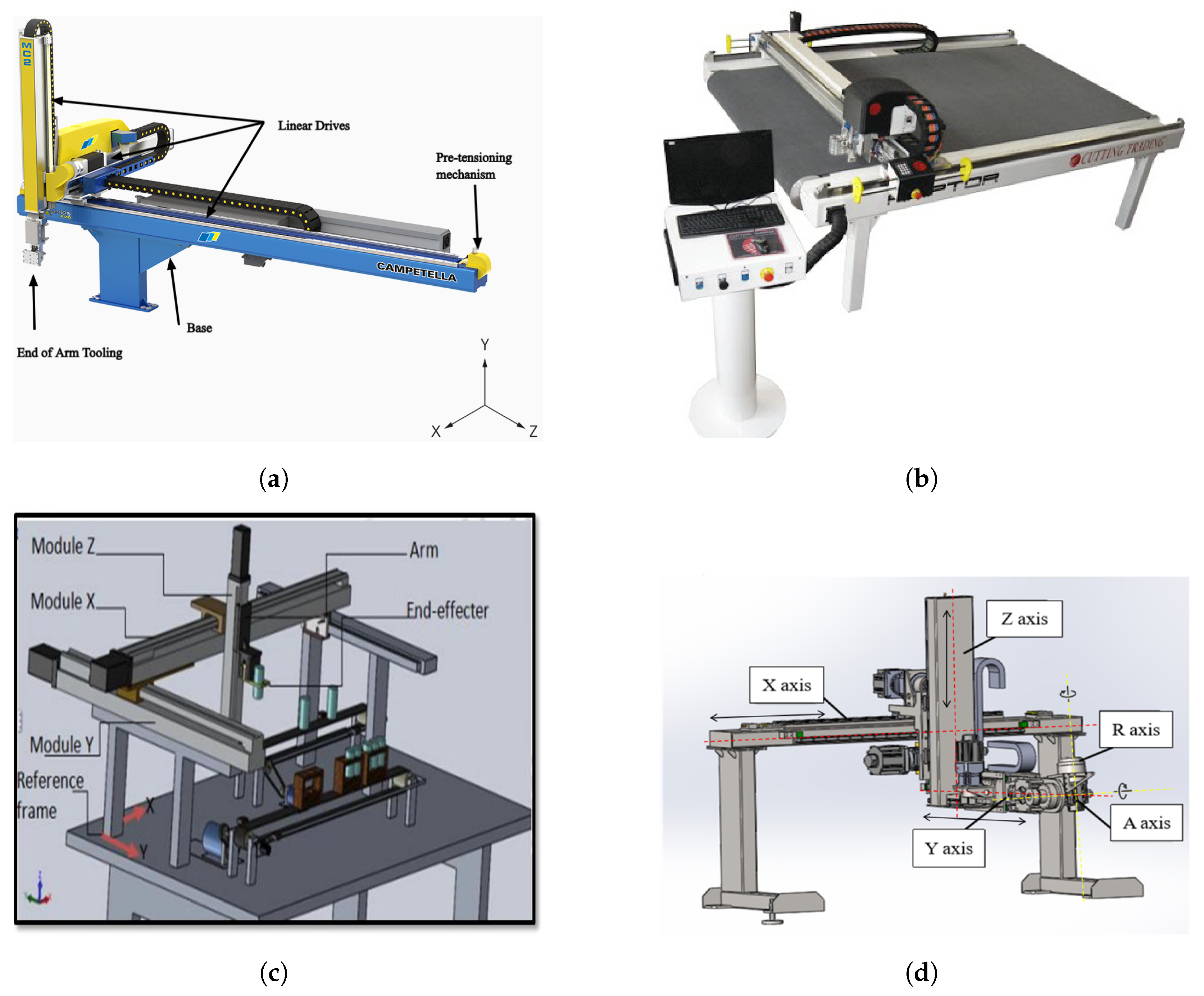
Cartesian robots can have different design configurations reflecting their flexible nature. This flexibility of Cartesian robots makes them suitable for different industrial needs and applications. Cartesian robots are easily customizable because of their flexible configuration, allowing them to meet the customer’s requirements in HMLV production applications. The different design configurations of the Cartesian robot are depicted in Figure 2 [6,7,8]. This figure presents various design configurations of Cartesian robots used in different applications from the existing literature. Each design in this figure provides unique features and advantages designed for specific industrial applications.
The design of a Cartesian robot and its implementation are presented in [9]. The design includes its mechanics, electronics, and control portion, which are then equipped with end-effector tooling to perform different manipulation tasks. The different design parameters and specifications of the three linear axes of the robot are reported in detail in this work. In addition, motion control software is developed to drive the robot in the desired trajectory. In [10], a dynamic model for a Cartesian manipulator is developed and then the parameters of the model are determined by simulations and experiments. A Laser Interferometry-Based Measurement System is used in this work to determine the shaft’s position. The design, manufacturing, and control implementation of a Cartesian robot with three prismatic joints are developed in [11]. Here, a PID controller is developed and tested experimentally for the position control of its end effector and to reduce the steady-state error in its trajectory. The design of a six-axis Cartesian robot is proposed in [12], whose application is in the automatic bending of metal sheets. In this work, the structural model and prototype of the Cartesian robot are proposed, its bending kinematics are verified using ADAMS software, and structural static and dynamic analyses are conducted using ANSYS software.
Normally, contact forces are approximated using force sensors, but in [13], a new method is introduced to calculate the contact force in the ball-screw drive of a Cartesian robot without using a force sensor. A disturbance observer and approximate friction compensation technique calculates the estimated force and then the jerk signal of this force is used to calculate the contact force. In [14], the position accuracy of the ball-screw-driven Cartesian robot is estimated by a Monte Carlo-based simulation method. The position accuracy is an important performance parameter; hence, this method provides a method to estimate it. Here, the position errors are estimated virtually instead of physically using the Monte Carlo technique. In another work, an experimental prototype of a three-axis Cartesian robot is developed to test different controllers [15]. Here, Cartesian control algorithms are developed with formal stability proofs derived using Lyapunov’s theory. A tuning rule is proposed for the developed controllers and the robot’s controller is tested experimentally to minimize the steady-state errors. Artificial intelligence has emerged as a transformative technology in industrial robotics, revolutionizing various aspects of manufacturing processes. It can be an important tool for the design optimization of robots with a flexible configuration. In [16], a software platform is proposed that facilitates the development of convolutional and feedforward neural networks for the parametric identification of Cartesian robots, offering a user-friendly interface and eliminating the need for extensive mathematical or programming knowledge. The main component of the Cartesian robot is a linear belt drive, and hence, its modeling and design analysis are very crucial.

2.1. Dynamic Modeling of Linear Belt Drives

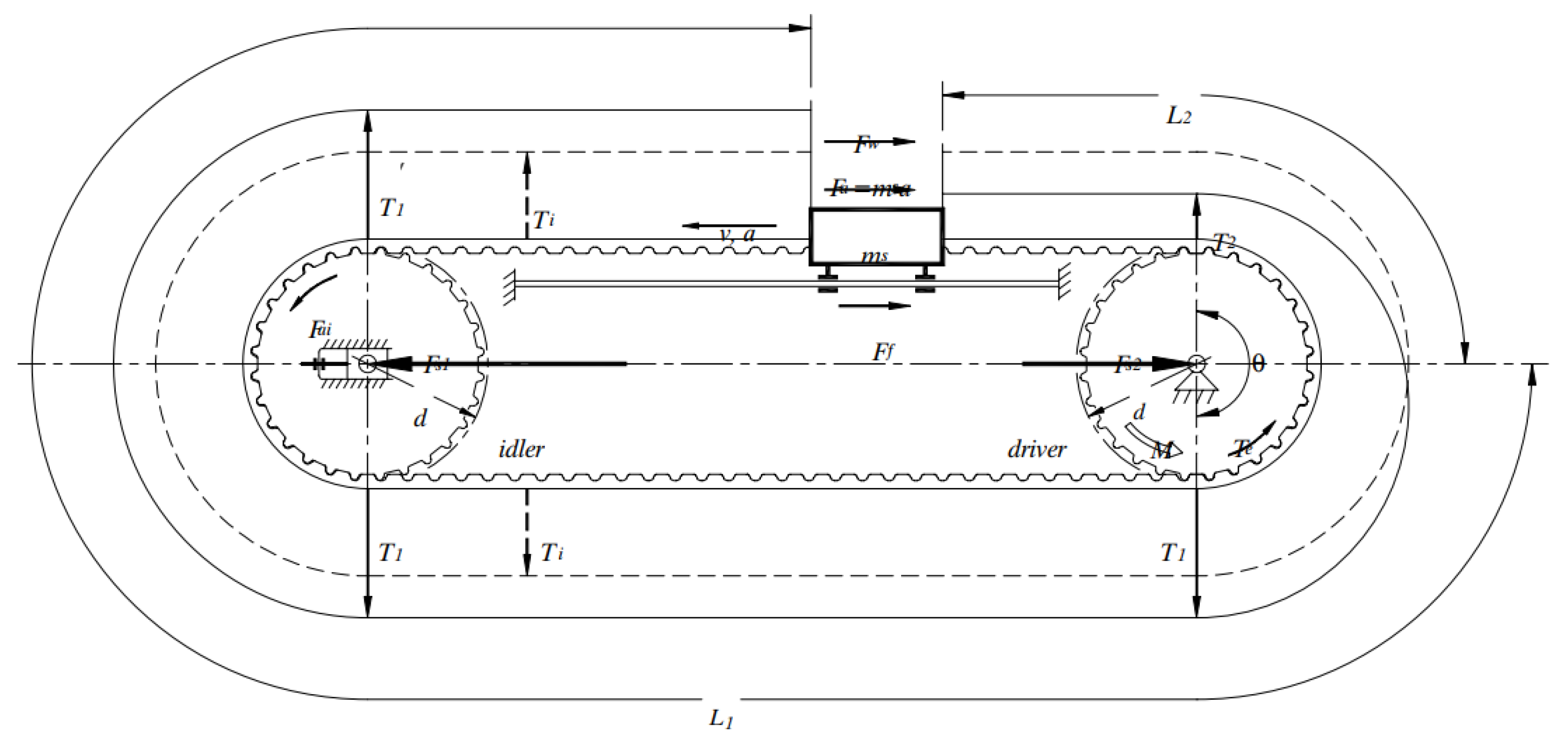
Mechanical transmission is a mandatory component of industrial robots and there are different types of transmission mechanisms available [17]. The most common transmission type used in Cartesian robots is a linear belt drive system. Synchronous belts are used for linear positioning applications in Cartesian robots because of their low positioning errors. The selection of the right timing belt in linear positioning applications is a very important step. The dynamics of belt drives have a huge impact on the performance of the Cartesian robots; hence, its accurate modeling and analysis is very important. The dynamics of the linear positioner configuration are well explained in the Gates Mectrol white paper on timing belt theory. An illustration of the linear positioner configuration from the Gates Mectrol paper is depicted in Figure 3 [18].
From this figure, the tension in the belt will be lower between the driver pulley and the movable mass if the mass is moving away from the driver pulley while it is higher in the rest of the belt and vice versa. The movable mass slides on linear guides that opposes its motion due to friction. We can see from this figure that the tensions in the belt depend on the position of the movable mass, and it varies during the motion. The working/longitudinal force F t required to drive the mass through the linear guides is equal to the sum of the acceleration force F a , the friction force F f , the component of the force required to overcome gravity F g (vertical drives), the force to run the idler pulley F a b , and the inertial forces of the belt F a i .
F t = F a + F f + F g + F a b + F a i
F t = m s · a + μ r · m s · g · cos β + m s · g · sin β + w b · L · b g · a + 2 · J i · α d
where m s , a, μ r , β , L, b, w b , J i , and α represent the movable mass, the acceleration, the coefficient of friction, the inclination angle, the length of the belt, the width of the belt, the specific weight of the belt, the inertia of the idler pulley, and its angular acceleration, respectively. An important design consideration for linear belt drives is that the belt must be properly pre-tensioned to achieve better performance and avoid belt damage. The minimum force F v required for proper pre-tensioning of a timing belt is given below [19]. This minimum pre-tension in the belt must be ensured in order to generate the force difference between the slack and tight sides. The force difference in both sections equals the tangential force.
F V 1 · F t
The preload must be equal or slightly higher than the tangential force and it must not be unnecessarily high. Higher pre-tension can cause high contact friction, which can damage the belt. There is a high chance of belt tooth jump if the belt does not have adequate pre-tension, especially in the longer belts. The effects of low pre-tension on the health of the belt of a Cartesian robot are analyzed in [20]. Here, the current data of the electric motor are recorded to verify that the belt is properly calibrated. These data are collected at different belt frequencies and different cycles. A machine learning-based diagnostics and prognostic model is developed using current data that identify belt looseness and also suggest a maintenance strategy.
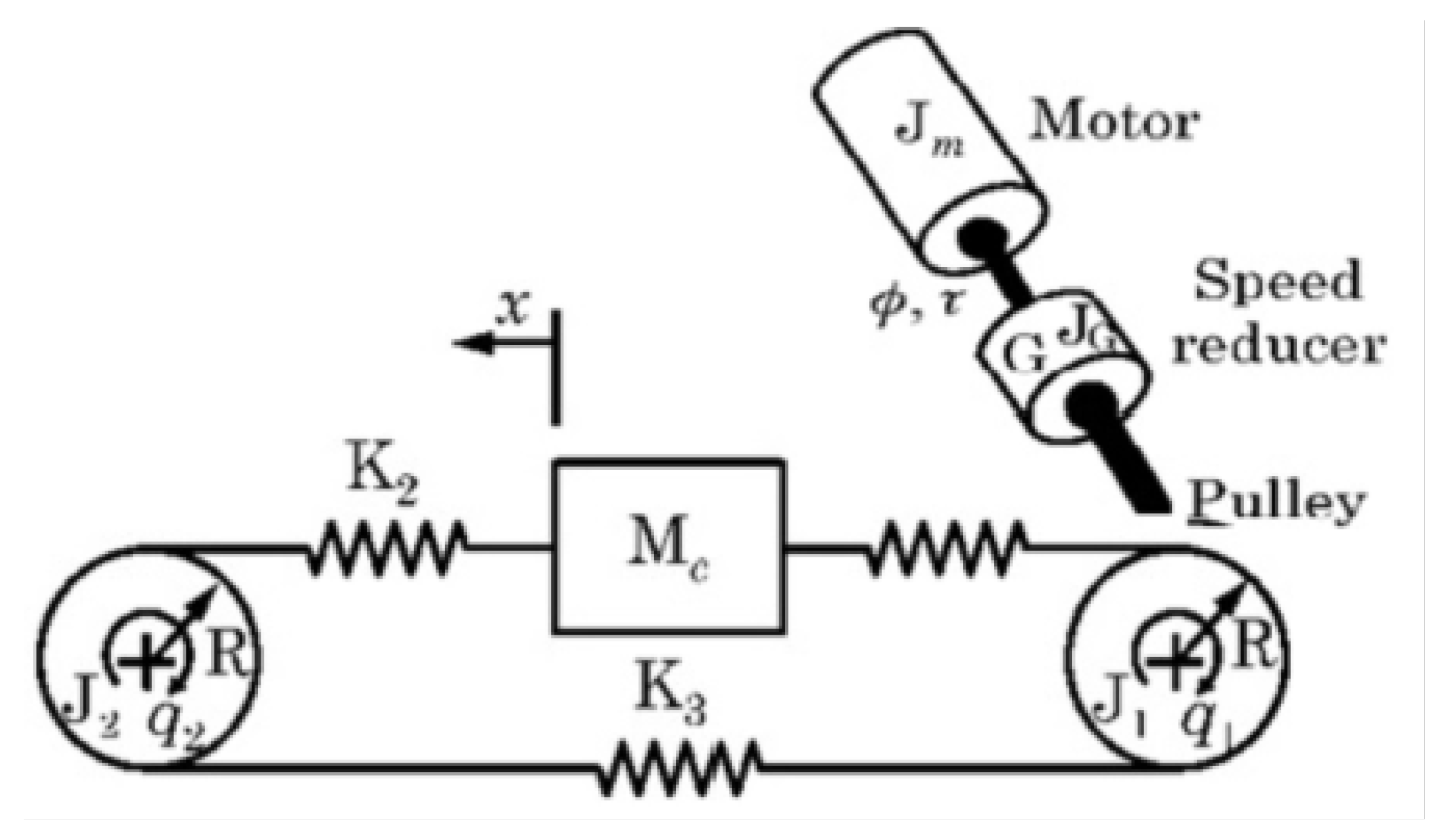
The linear belt drives of Cartesian robots are used for accurate positioning applications, and hence, deriving its dynamic model is important to simulate its behavior. The presence of nonlinear frictions and the belt’s elasticity make accurate positioning a challenging task; therefore, accurate dynamic models and robust controllers are important for linear drives. A spring–mass system is considered to derive the mathematical model of a linear drive as depicted in Figure 4 [21].
A three-mass model shown in Figure 4 can be used for the dynamic modeling of a linear drive that will yield a system of the 6th order. The 6th-order dynamic model equations for the belt–pulley system of a linear drive actuated by a motor derived by modal analysis are analyzed in [21,22,23,24].
J 1 + G 2 J G + J M q ¨ 1 + τ f 1 = G τ R K 1 ( x ) R q 1 x K 3 R q 2 R q 1 J 2 q ¨ 2 + τ f 2 = R K 2 ( x ) x R q 2 K 3 R q 2 R q 1 M x ¨ + F f = K 1 ( x ) R q 1 x K 2 ( x ) x R q 2
where J 1 , J 2 , J G , and J M correspond to the inertia of the driver pulley, driven pulley, gearbox, and motor, respectively. q 1 , q 2 , and K i represent the angular positions and stiffness, while τ , τ f 1 , and τ f 2 correspond to the input motor torque, the frictional torque of the driver pulley, and the driven pulley, respectively. Furthermore, G, R, M, x, and F f represent the gear ratio, pulley radius, cart mass, cart position, and cart friction force, respectively.
The three-mass model is highly nonlinear and complex; therefore, it can be converted to a two-mass system (4th order) by considering the inertia of the pulleys is small compared to the motor and load inertia [25,26,27]. The fourth-order model equations are written in the following way.
J e φ ¨ + τ f = τ L · K eff · w M x ¨ + F d i s t = K eff · w w = L φ x
where J e = J 1 + J 2 + G 2 ( J G + J M ) represents the equivalent inertia on the motor side and M represents the cart-side inertia. τ f and F d i s t depict constant frictional disturbances on both sides, and w and K eff denote the belt stretch and the equivalent stiffness, respectively. Here, L represents the transmission constant and φ is the angular position of the motor shaft. The dynamic system can be further simplified if L is assumed as unity.
J e w ¨ + K w w = τ τ w d i s t M x ¨ + F d i s t = K eff · w
where K w = K eff ( 1 + κ ) , τ w d i s t = τ f κ F d i s t , and κ = J e / M . The value of stiffness K eff is considered constant. The block diagram for the belt stretch model of a linear drive of a Cartesian robot is shown in Figure 5 [28].
The dynamic model can be converted into individual blocks, a transfer function, or a system of state-space equations, and then it can be simulated in MATLAB Simulink to analyze the results. The transfer functions from the input reference torque to the angular position of the motor and the position of the cart can be obtained from a two-mass model system as presented below [29,30].
φ m τ = 1 J e + M R 2 s 2 + b 1 s Rigid Part · M s 2 + b s s + K eff J e · M J e + M R 2 s 2 + b s s + K eff Flexible Part
x τ = 1 J e + M R 2 s 2 + b 1 s Rigid Part · b s s + K eff J e · M J e + M R 2 s 2 + b s s + K eff Flexible Part
Here, b s represents the damping constant of the belt, while b 1 represents the viscous friction. These transfer functions are separated into a rigid part and a flexible part where the rigid part represents integration from τ to x, while the flexible term presents the resonance behavior of the system. The resonance behavior of the whole system can be analyzed using these transfer functions. At low frequencies, the rigid part dominates the behavior of the system, while at high frequencies, resonances dominate, making the system more flexible. It can be seen that the flexibility of the belt is dependent on the effective stiffness. These transfer functions consider the damping of the belt and viscous frictions of the system for the damping analysis. The transfer functions are used for the vibration analysis of the belt drive, and they are further elaborated in the next section.
Typically, the effective stiffness is supposed to be constant during the motion of the cart to simplify the dynamic analysis. However, in the actual model, the stiffness value of the belt varies with the motion of the cart; therefore, the effective stiffness can be calculated by combining the three stiffness values [29,31,32,33]. The effective stiffness can be calculated from the equation below, where K 3 is independent of position. The equivalent stiffness depends on the position of the cart and thus makes the system nonlinear. When moving away from the driver pulley, the value of effective stiffness changes from high to low [29]. From the above transfer functions, it can be noticed that stiffness is one of the important design parameters that defines the resonances in the belt.
K eff ( x ) = K 1 ( x ) + 1 1 K 2 ( x ) + 1 K 3 = K 1 ( x ) + K 2 ( x ) · K 3 K 2 ( x ) + K 3 .
Friction is also an important parameter to consider while modeling linear belt drives. It depends on the position and direction of the motion. The nonlinear friction of the belt drive system is modeled in [33]. Some of the disadvantages of linear drives are the flexibility of the belt and nonlinear friction in the drive [33]. This affects the accuracy of the linear drive as it moves at very high speed. In this work, the analysis of both the non-linearities and their compensation is presented. Fast Fourier Transform (FFT) and Continuous Wavelet Transform (CWT) are generally used for fault diagnosis of the linear drive of a Cartesian robot [34]. These faults occur due to friction, tension, and overheating of the belts.

2.2. Modeling of Other Mechanical Drives

Although a linear belt drive is the most common drive mechanism used in Cartesian robots, there are also other less common drive methods, such as rack-and-pinion drive, ball-screw drive, and linear motor drive. These drives are selected on the basis of the design requirements and applications of the Cartesian robot. Rack-and-pinion drives are recommended for longer drive strokes and applications with a high load capacity. Ball-screw drives offer high-precision strokes and smooth motions due to low backlash but with a shorter stroke length. On the other hand, linear motor drives are direct drive mechanisms, which offer ultra-high speeds with higher accuracy and low backlash [35].
One disadvantage of the rack-and-pinion drive is the presence of backlash between the pinion and the rack. This backlash can be removed by electrically or mechanically pre-loading the drives. The preload influences the properties of a rack-and-pinion drive, such as the backlash, stiffness, bandwidth, and friction [36]. The preload can be increased up to a certain level to achieve the minimum backlash, and a further increase will increase only the friction, stiffness, and bandwidth. In [37], the backlash in the rack-and-pinion drive is determined by introducing a novel method. The acceleration signals from the motor and cart position sensors are used here for the backlash calculation. Estimated backlash calculation can help diagnose the changes in the backlash, which indicate the bad condition of the drive. The performance of rack-and-pinion drives is affected by nonlinear frictions and backlash. The effects of friction and backlash can be compensated by control-based compensation methods presented in [38]. The findings in this work confirmed the reduction in the friction, disturbance effects, and backlash of the rack-and-pinion drive. In [39], an adaptive pre-loading approach is developed, which will adjust the preload of the rack-and-pinion drive during operation. Here, the energy efficiency of the drive is increased by using adaptive pre-loading while maintaining high accuracy. The rack-and-pinion drives experience vibrations during their operation due to backlash and gear contact. These vibrations are reduced by the design optimization strategy proposed in [40]. A 5-DOF dynamic model of a rack-and-pinion drive is derived first to implement the optimization strategy.
Ball-screw drives are made up of a ball-screw nut with balls, a ball-screw shaft, and a thrust bearing at both ends. These drives are highly efficient because of their negligible clearance, high stiffness, and low stick–slip effect. The high positioning accuracy requirement is satisfied by the low backlash and high stiffness of the drive. The low backlash in the ball-screw drives is ensured by pre-loading the ball-screw nuts, which is achieved by adjusting the spacer or using oversized balls [35,41]. The dynamic behavior and the life span of the ball-screw drive are determined by their pre-loading. The pre-loading is linearly related to the velocity of the ball-screw drive only when the speed of the drive is high [42]. Here, the effective pre-tension is calculated using this linear correlation, and a new approach is developed to calculate the life span.
The motion in linear motor drives is generated by the magnetic force of its main and secondary parts. This force is high because there are no flexible components involved in the drive transmission system. This basically allows for its high speed motion and better positioning accuracy compared to other linear drives [43]. The high speed and load of the linear motor drive produce heat, which can cause thermal distortion, and this heat can be reduced by different cooling strategies. The heavy loads and high speeds of the servo drives can cause inertial vibrations by stimulating the low-frequency modes [44]. In this work, the modeling, simulation, and control strategies for the servo drive of a gantry machine are presented.

2.3. Vibration Analysis

The strokes of the Cartesian robots can be very large due to their large working area; therefore, they experience high accelerations. In some applications, the tool mounted on the end effector performs manipulation tasks, which generate reactive forces and noises. The reduction in and analysis of these noises and vibrations are very important in studying a Cartesian robot. The high-frequency vibrations generated by a pneumatic tool that is attached to the end effector of a Cartesian robot are analyzed and the issue is addressed using a tuned vibration absorber (TVA) in [6]. Here, the robot is used for cutting applications, which results in significant vibrations of the machine. A coupled model composed of an equivalent robotic model of the cutting head and a modal model of the moving rail is developed to analyze the vibration of the Cartesian cutting machine and validate the control strategies.
A Component Mode Synthesis (CMS) technique is used to derive the dynamics model for the structural vibration response of a Cartesian robot [45]. The model analysis predicts the vibrations generated as the result of the frictional forces and inertial forces of the robot when the drives move in its axis. The vibrations generated at the end effector of the robot are calculated using CMS and experimentation. The natural frequencies and mode shapes of the robot components are calculated in the static configuration and residual vibrations in the dynamic configurations to validate the CMS model. A tuned vibration absorber (TVA) can be used to reduce vibrations in the Cartesian robot and its components. The effect of a TVA on the vibrations generated by the Cartesian cutting robot is studied and predicted using the Sherman–Morrison formula in [46]. In this work, the vibrations induced by the cutting head during the motion that can excite the TVA are analyzed.
In [47], a vibration control technique for the end effector of the Cartesian robot is implemented using an input preshaping control, which yielded better results even with the conventional controller by reducing the vibration settling time of the arm end. Here, the robot’s working efficiency is enhanced by increasing the speed and reducing the cycle time, but this causes low-frequency vibrations at the arm end while decelerating, causing lag in the end-effector positioning. The maximum jerk value of the motion trajectory significantly influences the vibration amplitude of a Cartesian robot, and this influence can be correctly estimated using theoretical formulations derived and verified experimentally in [48]. This shows that input trajectories have an influence on vibrations developed in Cartesian robots.
The Cartesian robot used for metal cutting applications must be highly precise to achieve the required tolerances. In cutting applications while undergoing high accelerations, the accuracy of the robot is usually very low. For this purpose, a tuned mass damper (TMD) design is proposed that minimizes the amplitude of the vibrations generated in the robot [49]. The frequency analysis of the damper is performed to check its effectiveness and identify the parameters that impart vibrations. Here, two different models of a tuned mass damper were proposed and tested. To ensure the accuracy of robots for assembly operations, a precision assembly robot is developed and then the structural vibrations of the robot link are modeled using the Component Mode Synthesis (CMS) technique in [50], where the mode shapes are obtained for different components to calculate the approximate behavior of the whole robot. The model of the resonant characteristics of this robot is tested and compared with experimental results to analyze the performance. The vibration analysis in the different components of the Cartesian robot is summarized in Table 1.
In addition to the vibrations in the structure of Cartesian robots, vibrations in linear belt drives can also affect the performance of a Cartesian robot. Vibrations in the belt drive are the main source of vibrations in Cartesian robots, and vibration analysis of the belts is performed to predict the response of the system. The transfer functions presented in Equations (7) and (8) can be used to calculate the belt resonances. The denominator of the flexible part of both transfer functions is a quadratic polynomial, and it can be used to calculate the resonance frequency of the belt. The anti-resonance frequency can be calculated from the numerator of the transfer function of Equation (7). The resonating and anti-resonating frequency can be calculated as follows [29]:
f res = 1 2 π K eff J e + M R 2 J e M
f anti-res = 1 2 π K eff M
The value of the undamped natural frequency of the belt drive can be calculated using these equations. These equations present the frequency as a function of effective stiffness and inertia terms. Inertia terms are constant during the analysis, while the stiffness varies with x; therefore, the frequency varies as a function of the cart position. The resonance frequency is very high when the cart is at the starting position, while it reduces exponentially as the cart moves toward the final position. From this analysis, we can say that the resonance frequency depends on the position of the cart. This resonance causes inaccuracy in the position of the belt, which affects the linear drive performance.
Position control of belt drives is challenging due to their flexibility and vibrations. The positional accuracy of the linear belt drives is affected by vibrations in the belt. For accurate positioning and repeatability, the vibration in the belt must be minimized. There are different solutions available to reduce the effects of these vibrations. Methods for reducing vibrations are classified as passive methods, such as generating an optimum input reference trajectory and filtration of the reference torque, and active methods, such as control strategies [29]. Notch filters and feedback control strategies are widely used to reduce the resonance in belt drives. However, variation in the resonance dynamics of the belt due to its flexibility reduces the performance of these strategies. To resolve this issue of the linear belt drive, a resonance suppression technique is proposed in [51], where the model is separated into rigid and pure resonating parts and the damping of the resonating part is adjusted to avoid instability. Here, the damping is adjusted based on the reduced-order observer with a high-pass filter.
The belt of the linear drive becomes faulty after its use for a period of time. Faults in the timing belt can be diagnosed by analyzing the vibrations and noise of the pulley [52]. Here, the vibrations in the belt are measured and analyzed, and they are used to diagnose defects in the belt drive. Fault diagnosis of different parts of Cartesian robots is a difficult task. Vibrations in robot components can be used to diagnose faults. In addition to other causes, variation in the pre-tension of the pulley–belt system severely affects the gearbox of a Cartesian robot [53]. In this case, the gearbox fault diagnosis is performed by analyzing the mechanical vibrations of the gearbox. Different analyses have suggested that high belt tension increases vibrations in the belt but improves positioning accuracy. In the investigation of [54], the effect of the belt tension on the accuracy of the position and the vibrations of the timing belt of the Hirata Cartesian robot is analyzed. The longitudinal vibrations of the timing belt system of the gantry robot is analyzed and modeled using a three-mass model in [55]. In this work, the system’s response and its resonances are analyzed in both the undamped and damped cases.
Another issue associated with the timing belts of the linear drives according to the customer’s quality perception is noise generation during motion. The noise generated as a result of friction, impact, and air between the teeth of the timing belt and pulley is modeled and analyzed in [56,57]. These studies present the contribution of different tooth parameters and operating conditions in the generation of these noises. Measurement methods are presented for the analysis of air-induced noise generation in synchronous belts [58]. First, a Scanning Laser Doppler Vibrometer (SLDV) is used to record the acoustic data of the belts, and then it is used to perform the prediction analysis.
In addition to longitudinal vibrations, the amplitude and frequency of transverse vibrations in the belt of the linear drive are one of the parameters that ensures a smooth and precise motion. The transversal vibrations in the belt of a linear belt drive are modeled analytically, its solution is obtained using the FEM technique, and its frequency during the length variation while moving a mass is analyzed [59,60]. The linear belt drive vibration analysis that can affect the performance of the Cartesian robot is presented in Table 2.

2.4. Trajectory Planning

A Cartesian robot is an automatic industrial machine that follows a desired input trajectory to perform a task in any application. An input reference trajectory plays an important role in robotic applications as it provides optimum motion paths that are crucial for task executions while sticking to system constraints. Optimum trajectory generation is crucial in robotics as it allows for energy-efficient operation, smooth motion profiles, reduced robot vibration, and precise positioning. It improves robot performance and ensures reliable operation for various industrial applications.
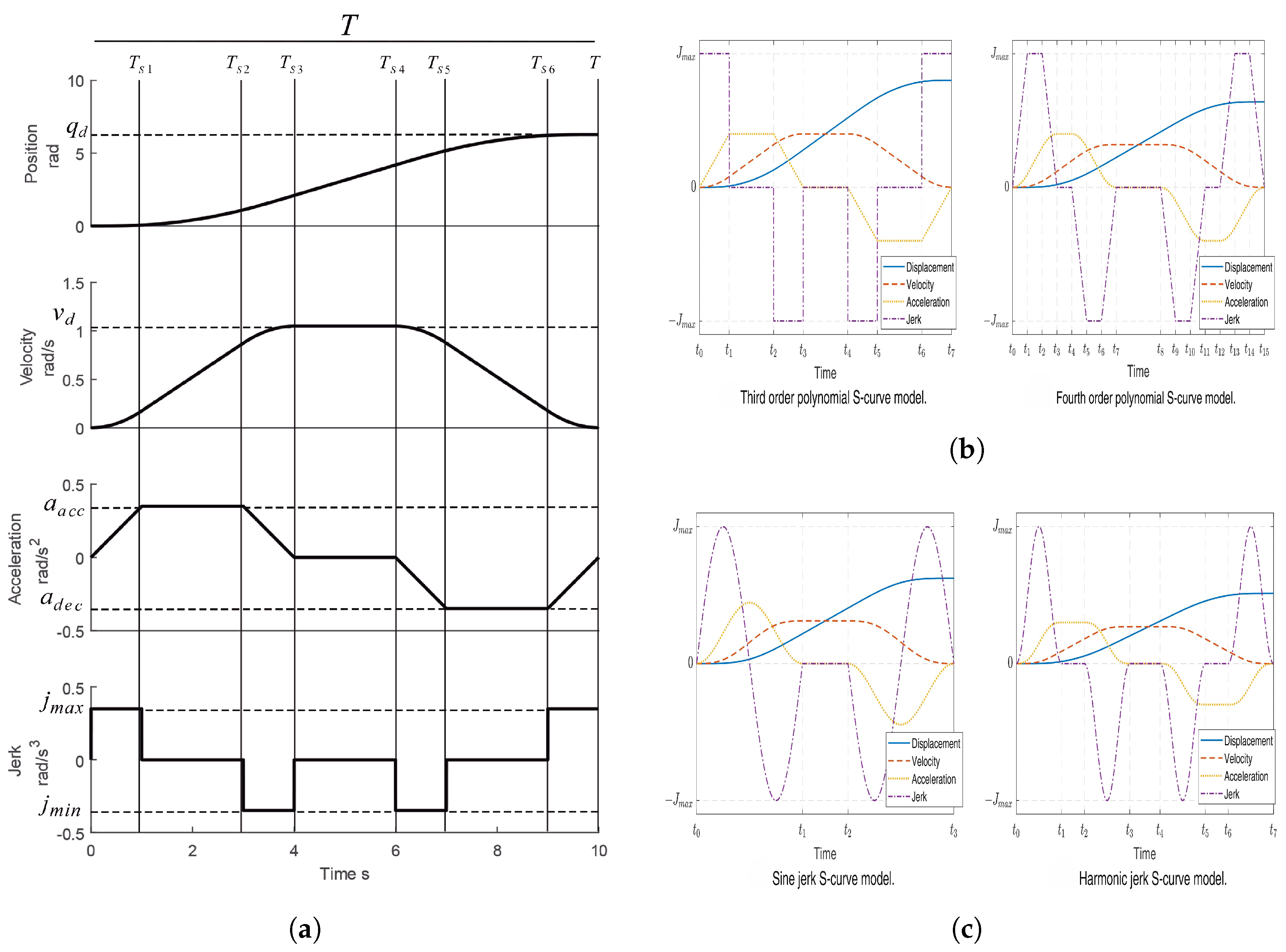
The reference trajectory and the controller are essential components of industrial robots. It implies that generating an optimal position trajectory and a robust controller is important to reduce resonances and improve precise positioning [29]. Generating a time-optimal motion trajectory as an input to the robot controller within the boundary conditions to perform any task is the objective of trajectory planning methods. Optimum trajectory can improve robot performance by reducing vibrations and generating energy-efficient and smooth motion profiles. The aim of the research on trajectory planning is to generate energy optimal trajectories that improve the robot’s performance. The reference trajectory can be generated by a point-to-point method and a contour method. The desired motion is defined by considering the initial point to a final point only in point-to-point trajectories. The contour method considers a set of via-points of the motion trajectory and these points must be interpolated properly. One of the common point-to-point motion profiles is a seven-segment profile, in which the motion curve is divided into seven segments [61,62,63,64]. In this motion curve, the body accelerates at the beginning until it reaches the maximum speed, and it stays at a constant speed for some time, after which it decelerates to zero velocity. This trajectory is commonly used as a reference input trajectory in Cartesian robots. In the point-to-point motion trajectory, the total time duration, maximum acceleration, velocity, and jerk are given as input to generate the desired profile. An S-curve point-to-point motion profile is a smooth and time-optimal trajectory profile, which can achieve the demands of high-speed and ultra-precision robot operations. There are different types of S-curve trajectory models that are used in the motion planning of industrial robots. The different point-to-point input motion trajectories are depicted in Figure 6 [64,65].
The increasing demand for online trajectory planners with bounds on velocity, acceleration, and jerk has led to significant development in time-optimal trajectory generation methods. Time-optimal trajectories are obtained by combining Finite Impulse Response (FIR) filters with multi-segment polynomial trajectories with constraints on its first n derivatives [66]. This work is further extended in [67], where a chain of rectangular smoothers is used to design computationally efficient trajectory generators of any higher order. This technique ensures an optimal trajectory in the event that the null boundary conditions are not satisfied by the filter parameters.
In addition to optimizing time, motion trajectories can also help minimize energy. An optimal motion profile is developed for the Cartesian robot to minimize energy usage while performing its task [68]. Analytical models are developed for the minimum energy trajectories of the linear drive of a Cartesian robot, and the results are validated experimentally in [69]. Here, dynamic and electromechanical models of a linear drive are developed and trajectories are proposed for the minimum motor energy consumption. Shaped reference trajectories are experimentally analyzed to reduce vibrations in a Cartesian robot while generating fast motions [70]. In this paper, the shaped inputs are based on the versine series-based force profile, which minimizes the excitation energy and increases the kinetic energy. Different energy efficient trajectories are designed for DC motor-actuated Cartesian robots through various optimization techniques, and then their efficiencies are tested [71,72].

2.5. Control Strategies for Cartesian Robots

Designing robust controllers is very important for Cartesian robots, as it directly influences their performance, accuracy, and efficiency in industrial applications. A well-designed and robust controller ensures precise position tracking, minimizes vibrations, and enhances overall system stability. Controllers play an important role in high-speed and high-precision operations in different industrial applications by optimizing motion trajectories, reducing energy consumption, and improving productivity. Robust controller designs tackle challenges such as parametric uncertainties, nonlinear friction, and varying stiffness in the system. It enables Cartesian robots to achieve optimum performance in various tasks and operating conditions.
The design principles of a linear drive are important for the motion control applications of the robot. Mechanical resonances and frictions present in the system depend on the design properties and can influence the controller’s performance. A centralized motion controller is developed for the position control of a linear belt drive of a Cartesian robot [29]. In this work, the parametric uncertainties in the belt drive model are analyzed and the performance of the system is evaluated with the variation in the parameters. A feedforward PID and a cascaded controller are tested first, but their performance is limited by external disturbances. The robustness and position accuracy of the system is ensured by developing a control using Quantitative Feedback Theory. Parameter estimation techniques can be used to design the controller for a given system. In [73], the parameter identification technique and advanced control strategies are presented for a linear belt drive system, which is subjected to nonlinear frictions and other mechanical complexities. Here, a frequency response function estimation followed by a parametric identification strategy is employed and then a robust controller is designed using the resulting system parameters to improve position tracking.
A robust controller composed of an inner-loop vibration controller and an outer-loop position controller is developed using VSS control theory for precise position tracking and reduced mechanical vibrations of a Cartesian laser cutting machine [28]. In this work, the uncertainties in the precise positioning of the laser-head of the machine caused by low-cost belt drives and elasticity are addressed using the two-loop controller. This issue of vibrations in the belt drive system caused by the elasticity of the belt is also addressed in [25]. Here, a robust sliding mode controller with an extended switching function to include non-rigid modes caused by the belt elasticity of a linear belt drive of a Cartesian robot is proposed and it effectively suppresses vibrations. The controller only uses sensory data on the angle of the motor and the position of the cart as feedback. The SMC controller generates an input that restricts the motion trajectory to a sliding manifold with reduced chattering. A sliding mode controller is designed for a linear belt drive system while considering nonlinear friction and variable belt stiffness [26]. Here, the sliding manifold is defined by load-side coordinates and belt stretch, combining the rigid and flexible dynamics of the system. The controller ensures better position tracking and suppresses vibrations. The aforementioned non-linearities are also considered in another work [27], where an SMC with an asymptotic disturbance observer is proposed that can compensate for any external disturbances. This controller reduces the position error peaks in amplitude and ensures accurate position tracking at both low and high speeds.
The oscillations of a suspended load from a gantry robot during its high-speed motion can be minimized by developing a fuzzy scheduled linear controller and a sliding mode controller [74]. The designed controllers are then tested with both the linear and nonlinear models of a gantry robot, and their effectiveness in reducing the vibrations is demonstrated. Control methods are developed for fast and slow motion applications of a Cartesian robot that captures flying objects [75]. Here, the capture point is predicted using sequential camera measurements that predict the position of the object and improve the accuracy of the capture point. Open- and closed-loop controllers are developed to control the DC motor of a Cartesian robot and the controllers are then experimentally tested [50]. An overall comparison of the control strategies mentioned above is tabulated in Table 3.

3. Virtual Prototyping of the Cartesian Robot

Virtual prototyping plays an important role in the design and development of Cartesian robots, and it helps to reduce both time and cost by minimizing the need for physical prototypes. It allows for extensive testing and validation of robot models under various operating conditions in a virtual environment prior to actual physical manufacturing. The kinematic and dynamic behavior of the robot is analyzed through virtual prototyping that offers insight into its performance, flexibility, and potential areas for improvement. Virtual prototype simulation and validation of the mechatronic systems of robots using DYMOLA software are discussed in [76]. A three-axis Cartesian-type machine is considered here as a test case and its transmission systems and control are modeled in DYMOLA. The results of the V.P model are experimentally validated, demonstrating the usefulness of the tool. Similarly, a virtual prototype is developed using DYMOLA for the linear axis of a machine used for milling application, specifically focusing on the disturbance forces produced due to contact [77]. The modeled axis has a belt and a ball-screw-type transmission and the system is controlled using a P/PI controller. Some performance indices of the machine are also approximated using the virtual prototype. A digital twin of the transmission axis of the Mandelli machine and its controller is developed using Modelica libraries and then the results are experimentally validated using additional sensors [78]. Virtual prototyping can also be used for the verification of embedded control system software using a co-simulation technique before deploying it on real hardware [79]. In this work, V.P of the belt drives of a Cartesian plotter is developed in the 20-sim software, and using this V.P, the embedded control software is then tested and validated via co-simulation. Real-time monitoring, visualization, and control of a gantry robot is achieved by establishing data communication between the actual robot and its virtual prototype developed in Unity to obtain real-time process parameters [80].
Virtual prototyping techniques such as multi-body dynamics and finite element analysis (FEA) are commonly used to simulate robot dynamics, structural behavior, and stress distribution under operating loads. Robot designers can analyze the impact of important factors such as vibrations, belt tension, and nonlinear frictions on a robot’s performance using these numerical methods. These techniques also allow us to evaluate different design configurations and robot performance virtually, which helps us to achieve a more optimized and robust robot design. The key indicators for the optimum performing robot are precision positioning, accurate trajectory tracking, low vibrations, reduced stresses, and minimum input energy.
The purpose of V.P is to focus on the design and development stage of a robot or machine. During this stage, the simulation results of the V.P model should be validated by experimental testing before finalizing the design. This can be performed by designing physical prototypes of the virtual models, and these models can be tested by providing the same conditions to validate the V.P results. Once the V.P model is validated, it can be approved as the final design with enhanced performance. The DYMOLA models developed for the X and Y axes of the machine are experimentally validated using the response to frequency sweep signals [76]. Here, the virtual model can predict the response with better accuracy, confirming its validity. The bode diagrams and the friction coefficient results of the digital model and experimental setup are validated confirming the reliability of the virtual models [78].
In summary, virtual prototyping not only streamlines the design process but also ensures that Cartesian robots can meet the demands of modern industrial applications through optimized and validated designs. The complex simulations and analysis of the Cartesian robots and their components through multi-body dynamics and finite element analysis tools are presented below.

3.1. Multi-Body Dynamics and Simulation

A multi-body model consists of many rigid or flexible links of a system connected through joints or force elements. It helps in studying the kinematic and dynamic behavior of the system and performing design optimization. There are different software solutions for performing multi-body simulations, which include MSC ADAMS, Dassault Systèmes SIMULIA, RecurDyn, Modelica, and some others. These tools helps in creating a virtual prototype of a robot, which helps to analyze the kinematic and dynamic behavior of the system and optimizing its design. In [12], a kinematic simulation model is developed using ADAMS for the analysis of the metal-bending process using a six-axis Cartesian robot. The simulations provide the speed and acceleration curves for all the axes of the robot, and this analysis serves as the basis for dynamic analysis and design optimization. Here, optimization design of the robot’s dynamics is performed to improve the positioning accuracy and response speed. In [81], the multi-body dynamics analysis of a timing belt is performed in a RecurDyn-based model to address the dynamic characteristics of the belt. The position, speed, and acceleration of the robot in three directions is analyzed and insights on the lateral vibrations of the belt are presented. This study helps in understanding the belt movement and its performance optimization.
One of the most important modeling criteria of the Cartesian robot is its dynamic performance, which includes its accuracy and feasibility. In [82], a coupled rigid–flexible model of a truss robot is developed, using MBS software RecurDyn and FEA software ANSYS. Here, the accuracy and efficiency of the coupled model is then verified through experiments. Then, the vibration acceleration amplitude in all the axes of the robot is obtained from the frequency-domain analysis. The motion of the robot should be smooth, as abrupt motions require very high actuator power. This problem is addressed in [83], where the dynamics of a 3-DOF gantry robot is modeled to avoid abrupt motions that exceed the actuator power capabilities. The model is developed in ADAMS and it provides understanding of the control strategies and the robot’s component design through analyzing the joint reaction forces and response of robotic links. Dynamic analysis involved applying various force values to joints with different time steps and durations, assuming negligible friction.

3.2. Finite Element Analysis

FEA is a numerical method that is used to solve complex engineering problems in order to predict how the design will react to the real-environment conditions. Different software tools are available for FEA, including but not limited to COMSOL, ANSYS, and MSC Marc. Cartesian robots are big machines that work under the influence of high forces and torques; hence, the reaction in different components of the robot needs to be analyzed. The stresses in the structure of the robot are analyzed by a finite element dynamic model in [5], when high inertial forces are generated in the robot during operation. It also helps to analyze the dynamical behavior of the Cartesian robot in the presence of vibrations. In ANSYS, an FE model for the sheet metal-bending robot is created to analyze structural deformation [12]. In this work, a static and dynamic analysis of the robot structure is carried out and the design of the Y and Z axes of the overhanging beams of the robot was optimized using the analytical results, improving the mechanics of the robot’s structural model. Experimental modal analysis and finite element analysis methods are applied to analyze the dynamics of a Cartesian robot and also to investigate the causes and effects of non-linearities caused due to sliding joints and electrical noises on the analysis results [84]. The dynamic behavior of an injection-molding Cartesian robot is analyzed using experimental and theoretical modal analysis in [85]. Here, the FEM results are obtained from COMSOL simulations, and these results are validated experimentally using the results obtained from CADA PC. This study helps in structural diagnoses, material optimization, and improvements in the robot’s design.
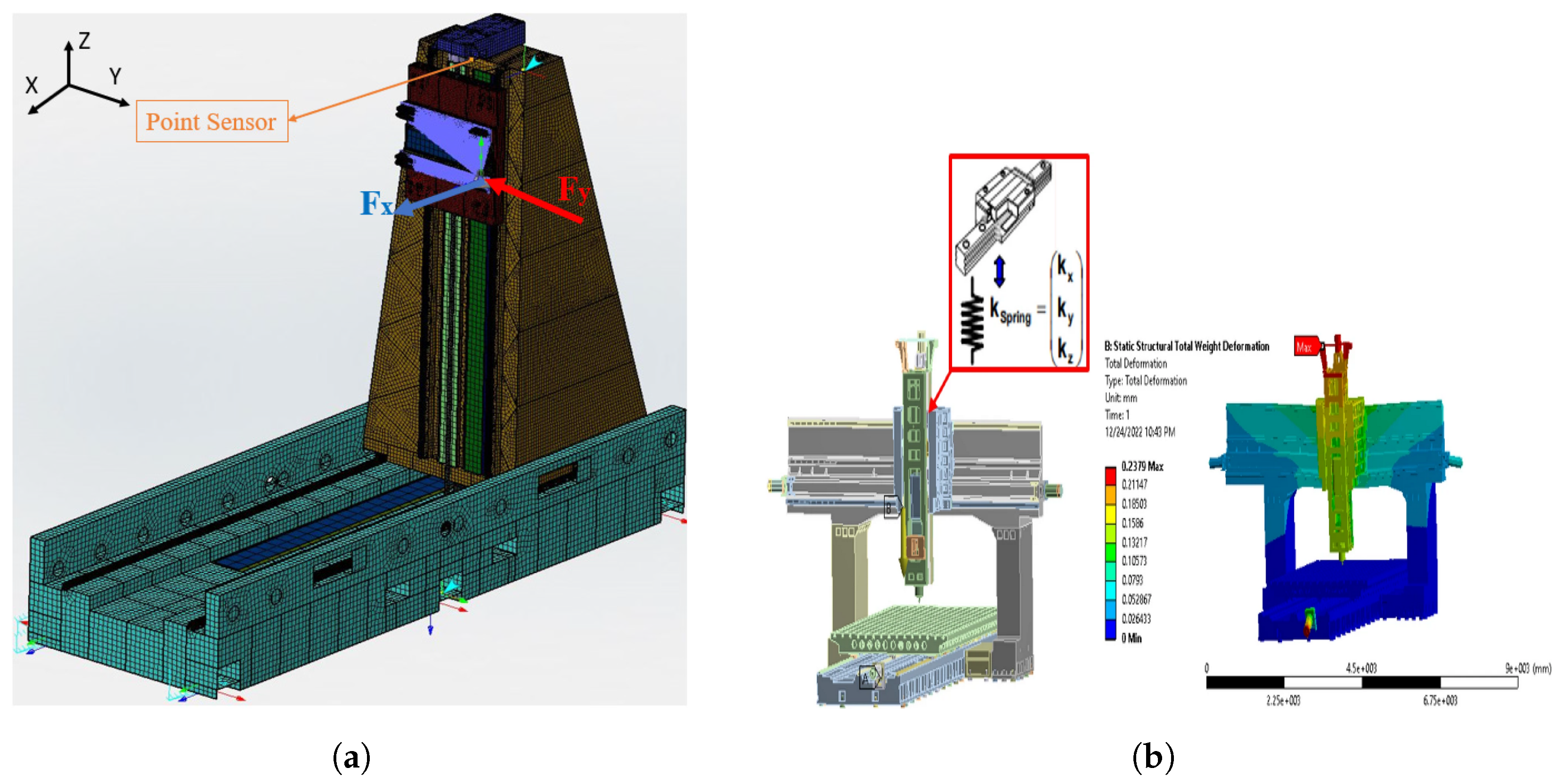
In [86], the resonance on the axis of the robot is compared with that of the entire Cartesian robot in the dynamic state. It shows that the resonance of the axis of the robot is independent of the whole structure. The static analysis is performed by the ANSYS workbench, while the motion analysis is performed by ADAMS. A finite element model of a complete Cartesian robot is developed using the MSC apex in [49], which is used to perform a modal analysis and frequency response analysis. Here, the vibrations of a high-precision metal cutting robot are minimized by a proposed tuned vibration absorber, and the FEM model validates its effectiveness. Similarly, static and dynamic analysis of a gantry precision machine is performed using FEA in [87], where the weak links of the robot are identified using structural analysis and it is also used to validate stiffness measurements and deformations. Two finite element simulation models of Cartesian robots from the literature are depicted in Figure 7 [49,87].

4. Optimization of Cartesian Robots

The main goal of optimization strategies is to improve the design and performance of the robot under any design constraint and operating condition. These strategies can help achieve better designs with enhanced performance in flexible robotic configurations. Different analytical and virtual prototyping strategies are used for the optimization of Cartesian robots and their drive mechanisms, each of which addresses specific challenges and proposes solutions. These optimization strategies include vibration reduction, control design, trajectory planning, and V.P simulation, and all of these strategies aim to improve overall robot performance. Each technique addresses a specific challenge in the performance of the robot by using different approaches. High structural and belt vibrations in the Cartesian robot can affect its positioning accuracy and the stability of the system. Tuned vibration absorbers and mass dampers, input motion preshaping, and noise reduction methods are used to resolve these problems. These techniques help to reduce the vibrations amplitude and improve system’s stability, thus enhancing the precise position tracking and performance [6,29,46,49,51].
The non-linearities, frictions, parametric uncertainties, and external disturbances of the Cartesian robots and their drives can be efficiently handled by robust control strategies. Different linear and nonlinear control strategies can be used to enhance the robot’s performance by improving precision positioning, reduced chattering, and compensating uncertainties and disturbances [26,27,29,73]. Trajectory planning can also optimize robot performance by reducing vibration excitation, limiting energy consumption, reducing cycle time, and avoiding abrupt motion of the robot. Trajectory planning results in smooth, time-optimal and energy-efficient reference motions of the robot using approaches such as point-to-point and contour methods and FIR filters [65,67,69,72].
V.P simulations also allow us to perform design and performance optimization of Cartesian robots. The optimization process often involves iterative simulations of different configurations of a robot where different design parameters are adjusted for each iteration to find the best trade-offs between the flexible configuration and performance of the robot. This design optimization approach is particularly useful for HMLV production environments, where the adaptability of the robot to different design configurations must be balanced by its performance. The design optimization process in the V.P software is performed in three steps: design study, design of experiments, and optimization. The robot design variables are systematically varied to analyze their impact on the performance parameters in the design study. Using design of experiments, the design space can be explored efficiently, and influential design variables are identified. The optimization algorithms can then refine the design by maximizing or minimizing the objective function while satisfying the applied constraints while performing iterative simulations. An optimum design of the robot that has an enhanced performance can be achieved using this iterative process within the virtual environment. This will reduce the development time and cost of the robot by using multi-body dynamics and FEA tools before building the physical robot [12,49,80]. Design and performance optimization using V.P is an underexplored area of research and has the potential to design and model state-of-the-art robots.

5. Conclusions

In this paper, a comprehensive review on analytical modeling, virtual prototyping, and optimization strategies of Cartesian robots with flexible configurations is presented. It analyzes the design and performance of customizable Cartesian robots in high-mix, low-volume production applications. The performance of the robot is affected due to its flexible configuration in HMLV production environments. Significant developments have been made in the design and performance optimization of Cartesian robots and their linear drives to meet the demands for their precision and adaptability. The analytical models of Cartesian robots and linear belt drives are discussed, which provide an overview of the dynamics, vibration reduction, control strategies, and trajectory planning. A relationship has been built between parameters such as nonlinear frictions, geometric properties, and belt elasticity and the performance of the Cartesian robot and linear belt drives. The modeling and design of other drive mechanisms such as rack-and-pinion drive, linear motor drive, and ball-screw drive is also discussed to provide a broader perspective. Vibration reduction strategies are presented to minimize the effects of vibrations and improve precision. In addition, input trajectory planning and control strategies have been investigated here, as the trajectory planning is essential for generating smooth and energy-efficient motion, while robust controllers ensure precise positioning and improved stability.
Virtual prototyping can play an important role in modeling and optimizing the robot in the development stage. It can significantly reduce the development time and cost of a flexibly configured Cartesian robot by simulating it under real-world conditions before creating a physical prototype. The effectiveness of V.P techniques such as multi-body dynamics and finite element analysis in the design optimization and performance enhancement of the Cartesian robot is reviewed. However, limited literature is available on the design and performance optimization of robots using V.P, which makes V.P an interesting topic for future research.
This review emphasizes the importance of ongoing research on the design optimization and performance enhancement of flexibly configured Cartesian robots. The integration of V.P techniques for optimization applications of robots highlights its potential in modern automation with special emphasis on flexibility and reliability. The findings of this article offer better insight for industries seeking to increase productivity while maintaining high levels of customization, performance, and operational efficiency.

6. Future Work

Even with advances in the analytical modeling and virtual prototyping of robots, there are still critical research gaps, especially on the issue of performance optimization. While a lot of literature is available related to the analytical modeling of linear drives and physical prototyping of Cartesian robots, comprehensive research work is still lacking on how virtual prototyping tools can be exploited in the design optimization and performance enhancement of robots. The main goal of this paper is to identify the research gap on the use of virtual prototyping and digital twins for design and performance optimization of robots in a flexible production environment.
This research gap can be filled in future research by using V.P techniques for the design and performance optimization of Cartesian robots. Virtual prototyping methods such as multi-body simulations and finite element analysis can be used to simulate robotic systems in real-world operating conditions. However, the full potential of these tools for the performance optimization of robots with a flexible configuration has not yet been utilized. These tools can simulate complex mechanical interactions, dynamics of the robot, generated forces, and vibrations that are quite hard to calculate in many instances with an analytical model. The incorporation of such simulations into the design and development process of the Cartesian robot could result in its more accurate performance predictions, and hence, such designs turn out to be more efficient. Additionally, the design and performance optimization of flexibly configured Cartesian robots using virtual prototyping tools and techniques have high potential for future research.
In order to utilize the potential of V.P, current and future research should focus on the employment of V.P techniques in the design and development stage to achieve optimum design and enhanced performance. Virtual prototyping technology can be further upgraded into creating digital twins where virtual and physical prototypes are integrated using real-time data transfer and it enables the continuous improvement of robots even during operation. This integration can help in real-time optimization while also reducing operating and maintenance costs.

Author Contributions

Y.M. and S.C. conceived and designed this study. Y.M. and F.C. conducted the literature review and data analysis. Y.M. wrote the initial draft of this manuscript. F.C. provided insights on the industrial applications and optimization techniques, while S.C. supervised the overall project and provided critical revisions to this manuscript. All authors have read and agreed to the published version of the manuscript.

Funding

This research received no external funding.

Institutional Review Board Statement

Not applicable.

Informed Consent Statement

Not applicable.

Conflicts of Interest

The authors declare no conflicts of interest.

References

  1. Dressler, I. Modeling and Control of Stiff Robots for Flexible Manufacturing. Ph.D. Thesis, Lund University, Lund, Sweden, 2012. [Google Scholar]
  2. Gruninger, R.; Kus, E.; Huppi, R. Market study on adaptive robots for flexible manufacturing systems. In Proceedings of the 2009 IEEE International Conference on Mechatronics, Malaga, Spain, 14–17 April 2009; pp. 1–7. [Google Scholar] [CrossRef]
  3. Wang, G.G. Definition and Review of Virtual Prototyping. J. Comput. Inf. Sci. Eng. 2003, 2, 232–236. [Google Scholar] [CrossRef]
  4. Gibson, I.; Gao, Z.; Campbell, I. A comparative study of virtual prototyping and physical prototyping. Int. J. Manuf. Technol. Manag. 2004, 6, 503–522. [Google Scholar] [CrossRef]
  5. Callegari, M.; Cannella, F.; Monti, S.; Santolini, C.; Pagnanelli, P. Dynamic models for the re-engineering of a high-speed Cartesian robot. In Proceedings of the 2001 IEEE/ASME International Conference on Advanced Intelligent Mechatronics. Proceedings (Cat. No.01TH8556), Como, Italy, 8–12 July 2001; Volume 1, pp. 560–565. [Google Scholar] [CrossRef]
  6. Bottin, M.; Cipriani, G.; Tommasino, D.; Doria, A. Analysis and Control of Vibrations of a Cartesian Cutting Machine Using an Equivalent Robotic Model. Machines 2021, 9, 162. [Google Scholar] [CrossRef]
  7. Sharath, G.S.; Hiremath, N.; Manjunatha, G. Design and analysis of gantry robot for pick and place mechanism with Arduino Mega 2560 microcontroller and processed using pythons. Mater. Today Proc. 2021, 45, 377–384. [Google Scholar] [CrossRef]
  8. Jiang, Q.; Cai, K.; Xu, F. Obstacle-avoidance path planning based on the improved artificial potential field for a 5 degrees of freedom bending robot. Mech. Sci. 2023, 14, 87–97. [Google Scholar] [CrossRef]
  9. Gasparetto, A.; Rosati, G. Design and Implementation of a Cartesian Robot. In AMST’02 Advanced Manufacturing Systems and Technology; Kulianic, E., Ed.; International Centre for Mechanical Sciences: Vienna, Austria, 2002; pp. 539–544. [Google Scholar] [CrossRef]
  10. De Waas Tilakaratna, P.; Shirinzadeh, B.; Alici, G. Model Development and System Identification of a Cartesian Manipulator Using a Laser-Interferometry Based Measurement System. IFAC Proc. Vol. 2004, 37, 401–406. [Google Scholar] [CrossRef]
  11. Madani, P.; Mobaraki, M.; Jahromi, S.; Fakhari, V. Experiental Robustness Evaluation of PID Controller for Position Control of a Cartesian Robot. In Proceedings of the 2019 7th International Conference on Robotics and Mechatronics (ICRoM), Tehran, Iran, 20–21 November 2019; pp. 526–531. [Google Scholar] [CrossRef]
  12. Xu, F.; Jiang, Q.; Rong, L.; Zhou, P.; Hu, J. Structural model and dynamic analysis of six-axis Cartesian coordinate robot for sheet metal bending. Int. J. Adv. Robot. Syst. 2019, 16, 1729881419861568. [Google Scholar] [CrossRef]
  13. Shimada, N.; Yoshioka, T.; Ohishi, K.; Toshimasa, M.; Yokokura, Y. Reliable force-sensorless contact detection method for ball screw drive cartesian robot. In Proceedings of the 2013 IEEE International Symposium on Industrial Electronics, Taipei, Taiwan, 28–31 May 2013; pp. 1–6. [Google Scholar] [CrossRef]
  14. Lee, S.J.; Chung, W.J.; Ju, J.H.; Park, K.B. Monte-Carlo Simulation Technique for Repeatability Analysis of 3-Axis Cartesian Robot Using Position Resolution of a Ball Screw; Ministry of Commerce, Industry and Energy (MOCIE) and Korea Industrial Technology Foundation (KOTEF): Sejong, Republic of Korea, 2010. [Google Scholar]
  15. Sanchez-Sanchez, P.; Reyes-Cortes, F.; Sanchez-Sanchez, P.; Reyes-Cortes, F. Cartesian Control for Robot Manipulators. In Robot Manipulators Trends and Development; IntechOpen: London, UK, 2010. [Google Scholar] [CrossRef]
  16. González-Arriaga, D.M.; Vargas-Treviño, M.A.D.; Vergara-Limon, S.; De León, C.L.C.D.; López-Gómez, J.; Vargas-Treviño, M.; Guerrero-García, J. Design of a Software Platform to Generate Convolutional Neural Networks for the Parametric Identification of a Cartesian Robot. IEEE Access 2023, 11, 63371–63387. [Google Scholar] [CrossRef]
  17. Karabegovic, I.; Banjanovic-mehmedovic, L. (Eds.) Industrial Robots: Design, Applications and Technology; Nova Science Pub Inc.: New York, NY, USA, 2020. [Google Scholar]
  18. Bertin, C. Timing Belt Theory. Available online: https://www.academia.edu/35140327/Timing_Belt_Theory (accessed on 14 June 2023).
  19. Perneder, R.; Osborne, I. Handbook Timing Belts. Handbook Timing Belts: Principles, Calculations, Applications; Springer: Berlin/Heidelberg, Germany, 2012. [Google Scholar] [CrossRef]
  20. Pierleoni, P.; Belli, A.; Palma, L.; Sabbatini, L. Diagnosis and Prognosis of a Cartesian Robot’s Drive Belt Looseness. In Proceedings of the 2020 IEEE International Conference on Internet of Things and Intelligence System (IoTaIS), Bali, Indonesia, 27–28 January 2021; pp. 172–176. [Google Scholar] [CrossRef]
  21. Minh, V.T.; Tamre, M.; Sekhri, E. Modeling and robust control algorithms for a linear belt driven system. Open Comput. Sci. 2018, 8, 142–153. [Google Scholar] [CrossRef]
  22. Sabanovic, A.; Sozbilir, O.; Goktug, G.; Sabanovic, N. Sliding mode control of timing-belt servosystem. In Proceedings of the 2003 IEEE International Symposium on Industrial Electronics (Cat. No.03TH8692), Rio de Janeiro, Brazil, 9–11 June 2003; Volume 2, pp. 684–689. [Google Scholar] [CrossRef]
  23. Sollmann, K.; Jouaneh, M. Dynamic modelling of a single-axis belt-drive system. Int. J. Model. Identif. Control 2011, 12, 386–394. [Google Scholar] [CrossRef]
  24. Katsioula, A.G.; Karnavas, Y.L.; Boutalis, Y.S. An enhanced simulation model for DC motor belt drive conveyor system control. In Proceedings of the 2018 7th International Conference on Modern Circuits and Systems Technologies (MOCAST), Thessaloniki, Greece, 7–9 May 2018; pp. 1–4. [Google Scholar] [CrossRef]
  25. Hace, A.; Jezernik, K.; Sabanovic, A. A new robust position control algorithm for a linear belt-drive. In Proceedings of the IEEE International Conference on Mechatronics, ICM ’04, Istanbul, Turkey, 3–5 June 2004; pp. 358–363. [Google Scholar] [CrossRef]
  26. Hace, A.; Jezernik, K.; Sabanovic, A. Improved design of VSS controller for a linear belt-driven servomechanism. IEEE/ASME Trans. Mechatron. 2005, 10, 385–390. [Google Scholar] [CrossRef]
  27. Hace, A.; Jezernik, K.; Sabanovic, A. SMC With Disturbance Observer for a Linear Belt Drive. IEEE Trans. Ind. Electron. 2007, 54, 3402–3412. [Google Scholar] [CrossRef]
  28. Hace, A.; Jezernik, K.; Terbuc, M. VSS motion control for a laser-cutting machine. Control Eng. Pract. 2001, 9, 67–77. [Google Scholar] [CrossRef]
  29. Jokinen, M. Centralized Motion Control of a Linear Tooth Belt Drive: Analysis of the Performance and Limitations; Lappeenranta University of Technology: Lappeenranta, Finland, 2010. [Google Scholar]
  30. Parkkinen, J.; Jokinen, M.; Niemela, M.; Lindh, T.; Pyrhonen, J. Motion synchronization of two linear tooth belt drives using cross-coupled controller. In Proceedings of the 2013 15th European Conference on Power Electronics and Applications (EPE), Lille, France, 2–6 September 2013; pp. 1–7. [Google Scholar] [CrossRef]
  31. Nevaranta, N.; Parkkinen, J.; Niemelä, M.; Lindh, T.; Pyrhönen, O.; Pyrhönen, J. Recursive identification of linear tooth belt-drive system. In Proceedings of the 2014 16th European Conference on Power Electronics and Applications, Lappeenranta, Finland, 26–28 August 2014; pp. 1–8. [Google Scholar] [CrossRef]
  32. Nevaranta, N.; Parkkinen, J.; Lindh, T.; Niemelä, M.; Pyrhönen, O.; Pyrhönen, J. Online Estimation of Linear Tooth Belt Drive System Parameters. IEEE Trans. Ind. Electron. 2015, 62, 7214–7223. [Google Scholar] [CrossRef]
  33. Jokinen, M.; Saarakkala, S.; Niemela, M.; Pollanen, R.; Pyrhonen, J. Physical drawbacks of linear high-speed tooth belt drives. In Proceedings of the Automation and Motion 2008 International Symposium on Power Electronics, Electrical Drives, Ischia, Italy, 11–13 June 2008; pp. 872–877. [Google Scholar] [CrossRef]
  34. Autsou, S.; Vaimann, T.; Rassõlkin, A.; Asad, B.; Kudelina, K.; Hyunh, V.K. Fault Diagnosis of the Tooth Belt Transmission of Cartesian Robot. In Proceedings of the 2022 29th International Workshop on Electric Drives: Advances in Power Electronics for Electric Drives (IWED), Moscow, Russia, 26–29 January 2022; pp. 1–6. [Google Scholar] [CrossRef]
  35. Altintas, Y.; Verl, A.; Brecher, C.; Uriarte, L.; Pritschow, G. Machine tool feed drives. CIRP Ann. 2011, 60, 779–796. [Google Scholar] [CrossRef]
  36. Engelberth, T.; Apprich, S.; Friedrich, J.; Coupek, D.; Lechler, A. Properties of electrically preloaded rack-and-pinion drives. Prod. Eng. 2015, 9, 269–276. [Google Scholar] [CrossRef]
  37. Zenn, W.; Keck, A.; Beck, M.; Herold, S.; Melz, T. Automated backlash determination on rack-and-pinion drives. In Proceedings of the 2023 IEEE/ASME International Conference on Advanced Intelligent Mechatronics (AIM), Seattle, WA, USA, 28–30 June 2023; pp. 1202–1207. [Google Scholar] [CrossRef]
  38. Karim, A.; Lindner, P.; Verl, A. Control-based compensation of friction and backlash within rack-and-pinion drives. Prod. Eng. 2018, 12, 589–596. [Google Scholar] [CrossRef]
  39. Verl, A.; Engelberth, T. Adaptive preloading for rack-and-pinion drive systems. CIRP Ann. 2018, 67, 369–372. [Google Scholar] [CrossRef]
  40. Choi, Y.H.; Choi, E.Y.; Jang, S.H.; Park, H.M.; Ha, J.S. Vibration analysis and dynamic optimization of a rack and pinion typed feed drive system for a router machine. In Proceedings of the ICMIT 2005: Control Systems and Robotics, SPIE, Chongqing, China, 20–23 September 2006; Volume 6042, pp. 961–966. [Google Scholar] [CrossRef]
  41. Brecher, C.; Weck, M. Feed Axes in Machine Tools. In Machine Tools Production Systems 3; Springer: Wiesbaden, Germany, 2021; pp. 7–106. [Google Scholar] [CrossRef]
  42. Verl, A.; Frey, S. Correlation between feed velocity and preloading in ball screw drives. CIRP Ann. 2010, 59, 429–432. [Google Scholar] [CrossRef]
  43. Pritschow, G.; Philipp, W. Direct Drives for High-Dynamic Machine Tool Axes. CIRP Ann. 1990, 39, 413–416. [Google Scholar] [CrossRef]
  44. Zirn, O. Machine Tool Analysis: Modelling, Simulation and Control of Machine Tool Manipulators; ETH Zürich: Zürich, Switzerland, 2008. [Google Scholar] [CrossRef]
  45. Reynoso, A. Structural Dynamics Model of a Cartesian Robot. Doctoral Dissertation, Massachusetts Institute of Technology, Cambridge, MA, USA, 1985. [Google Scholar]
  46. Bottin, M.; Cipriani, G.; Tommasino, D.; Doria, A. Control of the Vibrations of a Cartesian Automatic Machine. In Mechanism Design for Robotics; Zeghloul, S., Laribi, M.A., Arsicault, M., Eds.; Mechanisms and Machine Science; Springer: Cham, Switzerland, 2021; pp. 236–243. [Google Scholar] [CrossRef]
  47. Yamamoto, T.; Tanaka, K.; Sumiyoshi, M. Vibration control for cartesian 3 axes robot. In Proceedings of the 4th IEEE International Workshop on Advanced Motion Control—AMC ’96—MIE, Mie, Japan, 18–21 March 1996; Volume 2, pp. 647–652. [Google Scholar] [CrossRef]
  48. Barre, P.J.; Bearee, R.; Borne, P.; Dumetz, E. Influence of a Jerk Controlled Movement Law on the Vibratory Behaviour of High-Dynamics Systems. J. Intell. Robot. Syst. 2005, 42, 275–293. [Google Scholar] [CrossRef]
  49. D’Imperio, S.; Berruti, T.M.; Gastaldi, C.; Soccio, P. Tunable Vibration Absorber Design for a High-Precision Cartesian Robot. Robotics 2022, 11, 103. [Google Scholar] [CrossRef]
  50. Benjamin, M.; Garcia-Reynoso, A.; Seering, W. Dynamic and vibration modeling of a cartesian robot. In Proceedings of the 1985 IEEE International Conference on Robotics and Automation Proceedings, St. Louis, MO, USA, 25–28 March 1985; Volume 2, pp. 990–995. [Google Scholar] [CrossRef]
  51. Zheng, L.; Guan, Q.; Wang, X.; Luo, Y.; Wu, Y. A Robust Resonance Suppression Method for Linear Tooth Belt Drive with Variable Resonance Frequency. IEEE Trans. Ind. Electron. 2024, 71, 10346–10355. [Google Scholar] [CrossRef]
  52. Basso, R.; Fanti, G. Vibration Monitoring for Local Fault Detection in Synchronous Belts; American Society of Mechanical Engineers Digital Collection: New York, NY, USA, 2009; pp. 577–583. [Google Scholar] [CrossRef]
  53. Autsou, S.; Vaimann, T.; Rassõlkin, A.; Kudelina, K. Fault Diagnosis System of Cartesian Robot for Various Belt Tension. In Proceedings of the 2022 International Conference on Diagnostics in Electrical Engineering (Diagnostika), Pilsen, Czech Republic, 6–8 September 2022; pp. 1–4. [Google Scholar] [CrossRef]
  54. Autsou, S.; Vaimann, T.; Rassõlkin, A.; Kudelina, K.; Asad, B. Influence of Different Tooth Belt Transmission Faults on the Work of a Cartesian Robot. In Proceedings of the 2022 20th International Conference on Mechatronics—Mechatronika (ME), Pilsen, Czech Republic, 7–9 December 2022; pp. 1–5. [Google Scholar]
  55. Zhao, Z.H.; Jiang, X.M.; Du, Y.H. Design of Gantry Robot for Dye Dispense and Analysis of Vibration of its Synchronous Belt Driven and Positioning System. Key Eng. Mater. 2011, 458, 313–318. [Google Scholar] [CrossRef]
  56. Chen, G.S.; Zhen, H.; Qatu, M. Noise Modeling of Synchronous Belts. Noise Vib. Worldw. 2013, 44, 14–27. [Google Scholar] [CrossRef]
  57. Sheng, G.; Zheng, H.; Qatu, M.; Dukkipati, R.V. Modelling of friction-induced noise of timing belt. Int. J. Veh. Noise Vib. 2008, 4, 285–303. [Google Scholar] [CrossRef]
  58. Sante, R.D.; Revel, G.M.; Rossi, G.L. Measurement techniques for the acoustic analysis of synchronous belts. Meas. Sci. Technol. 2000, 11, 1463. [Google Scholar] [CrossRef]
  59. Schnürer, D.; Holl, H.J. Transversal vibrations of a toothed belt in linear drives during operation. PAMM 2021, 20, e202000026. [Google Scholar] [CrossRef]
  60. Schnürer, D.; Holl, H.J. Frequency analysis of transversal vibrations of belt drives with time-varying belt lengths. PAMM 2021, 21, e202100186. [Google Scholar] [CrossRef]
  61. Liu, S. An on-line reference-trajectory generator for smooth motion of impulse-controlled industrial manipulators. In Proceedings of the 7th International Workshop on Advanced Motion Control, Proceedings (Cat. No. 02TH8623), Maribor, Slovenia, 3–5 July 2002; pp. 365–370. [Google Scholar] [CrossRef]
  62. Mu, H.; Zhou, Y.; Yan, S.; Han, A. Third-order trajectory planning for high accuracy point-to-point motion. Front. Electr. Electron. Eng. China 2009, 4, 83–87. [Google Scholar] [CrossRef]
  63. Blejan, M.; Blejan, R. Mathematics for Real-Time S-Curve Profile Generator. Hidraulica 2020, 4, 7–25. [Google Scholar]
  64. García-Martínez, J.R.; Rodríguez-Reséndiz, J.; Cruz-Miguel, E.E. A New Seven-Segment Profile Algorithm for an Open Source Architecture in a Hybrid Electronic Platform. Electronics 2019, 8, 652. [Google Scholar] [CrossRef]
  65. Fang, Y.; Hu, J.; Liu, W.; Shao, Q.; Qi, J.; Peng, Y. Smooth and time-optimal S-curve trajectory planning for automated robots and machines. Mech. Mach. Theory 2019, 137, 127–153. [Google Scholar] [CrossRef]
  66. Biagiotti, L.; Melchiorri, C. FIR filters for online trajectory planning with time- and frequency-domain specifications. Control Eng. Pract. 2012, 20, 1385–1399. [Google Scholar] [CrossRef]
  67. Biagiotti, L.; Melchiorri, C. Trajectory generation via FIR filters: A procedure for time-optimization under kinematic and frequency constraints. Control Eng. Pract. 2019, 87, 43–58. [Google Scholar] [CrossRef]
  68. Joy, M.P.M. Energy Optimal Motion Profile Generation for Cartesian Robot Driven by Linear Tooth Belt Drives. 2023. Available online: https://lutpub.lut.fi/handle/10024/166165 (accessed on 3 November 2023).
  69. Scalera, L.; Carabin, G.; Vidoni, R.; Gasparetto, A. Minimum-Energy Trajectory Planning for Industrial Robotic Applications: Analytical Model and Experimental Results. In Advances in Service and Industrial Robotics; Mechanisms and Machine Science; Springer: Cham, Switzerland, 2020; pp. 334–342. [Google Scholar] [CrossRef]
  70. Meckl, P.H.; Seering, W.P. Experimental Evaluation of Shaped Inputs to Reduce Vibration for a Cartesian Robot. J. Dyn. Syst. Meas. Control 1990, 112, 159–165. [Google Scholar] [CrossRef]
  71. Boscariol, P.; Richiedei, D. Energy-efficient design of multipoint trajectories for Cartesian robots. Int. J. Adv. Manuf. Technol. 2019, 102, 1853–1870. [Google Scholar] [CrossRef]
  72. Boscariol, P.; Caracciolo, R.; Richiedei, D. Energy Optimal Design of Jerk-Continuous Trajectories for Industrial Robots. In Advances in Italian Mechanism Science; Niola, V., Gasparetto, A., Eds.; Mechanisms and Machine Science; Springer: Cham, Swizerland, 2021; pp. 318–325. [Google Scholar] [CrossRef]
  73. Gruber, D. Self-Commissioning of Linear Toothed Belt Drives. Ph.D. Thesis, Technische Universität Wien, Vienna, Austria, 2017. [Google Scholar] [CrossRef]
  74. Meressi, T. Modeling and control of a three dimensional gantry robot. In Proceedings of the 37th IEEE Conference on Decision and Control (Cat. No.98CH36171), Tampa, FL, USA, 18 December 1998; Volume 2, pp. 1514–1515. [Google Scholar]
  75. Frank, H.; Barteit, D.; Meyer, M.; Mittnacht, A.; Novak, G.; Mahlknecht, S. Optimized Control Methods for Capturing Flying Objects with a Cartesian Robot. In Proceedings of the 2008 IEEE Conference on Robotics, Automation and Mechatronics, Chengdu, China, 21–24 September 2008; pp. 160–165. [Google Scholar] [CrossRef]
  76. Ferretti, G.; Magnani, G.; Rocco, P. Virtual prototyping of mechatronic systems. Annu. Rev. Control 2004, 28, 193–206. [Google Scholar] [CrossRef]
  77. Ferretti, G.; Lucchini, F.; Magnani, G.; Rocco, P. A mechatronic approach to the control of machine tools. IFAC Proc. Vol. 2005, 38, 228–233. [Google Scholar] [CrossRef]
  78. Scaglioni, B.; Ferretti, G. Towards digital twins through object-oriented modelling: A machine tool case study. IFAC-PapersOnLine 2018, 51, 613–618. [Google Scholar] [CrossRef]
  79. Groothuis, M.; Damstra, A.; Broenink, J. Virtual prototyping through co-simulation of a Cartesian plotter. In Proceedings of the 2008 IEEE International Conference on Emerging Technologies and Factory Automation, Hamburg, Germany, 15–18 September 2008; pp. 697–700. [Google Scholar] [CrossRef]
  80. Wang, H.; Yang, Z.; Zhang, Q.; Sun, Q.; Lim, E. A Digital Twin Platform Integrating Process Parameter Simulation Solution for Intelligent Manufacturing. Electronics 2024, 13, 802. [Google Scholar] [CrossRef]
  81. Yang, G.; Yang, L.; Cao, M. Simulation analysis of timing belt movement characteristics based on RecurDyn. Vibroeng. Procedia 2019, 22, 13–18. [Google Scholar] [CrossRef]
  82. Zhu, H.; Wang, B.; Chen, W. Dynamic performance analysis of truss robot based on RecurDyn and experimental research. In Proceedings of the 2016 Asia-Pacific Conference on Intelligent Robot Systems (ACIRS), Tokyo, Japan, 20–22 July 2016; pp. 31–35. [Google Scholar] [CrossRef]
  83. Mahir, A.I.I.; Deng, S.P.; Qi, Y.M. Gantry Robot Dynamic Analysis Based on Lagrange’s Motion Equation. Key Eng. Mater. 2016, 693, 1741–1746. [Google Scholar] [CrossRef]
  84. Pisoni, A.; Santolini, C.; Tomasini, E. Modal Analysis of a Cartesian Robot: Noise and Non-lineax Effeas. In Proceedings of the Proceedings—SPIE the International Society for Optical Engineering, Kona, HI, USA, 17–18 March 1994. [Google Scholar]
  85. Fan, C.W.; Tu, T.Y.; Chen, C.W. Modal Analysis and Static Structure Analysis for 3-Axis Cartesian Robot Used in Injection Molding Machine; American Society of Mechanical Engineers Digital Collection: New York, NY, USA, 2023. [Google Scholar] [CrossRef]
  86. Xu, G. The dynamic characteristic analysis on Cartesian coordinate robot. IOP Conf. Ser. Earth Environ. Sci. 2020, 474, 032003. [Google Scholar] [CrossRef]
  87. Chan, T.C.; Ullah, A.; Roy, B.; Chang, S.L. Finite element analysis and structure optimization of a gantry-type high-precision machine tool. Sci. Rep. 2023, 13, 13006. [Google Scholar] [CrossRef]
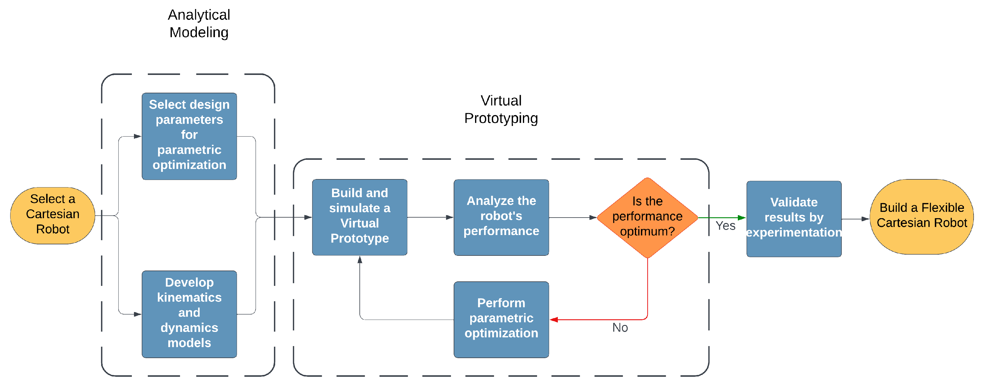
Figure 1. Modeling, simulation, and optimization strategy of a flexible robot.
Robotics 14 00062 g001
Figure 2. Different design configurations for Cartesian robots. (a) Schematic diagram of a Cartesian robot. (b) A Cartesian cutting robot [6]. (c) Gantry robot design [7]. (d) A 5 DOF Cartesian bending robot [8].
Robotics 14 00062 g002
Figure 3. Linear positioner configuration [18].
Robotics 14 00062 g003
Figure 4. Schematic representation of spring–mass system of a linear drive [21].
Robotics 14 00062 g004
Figure 5. Block diagram for the belt stretch model of a linear drive [28].
Robotics 14 00062 g005
Figure 6. Motion profiles for trajectory planning of industrial robots. (a) Seven-segment motion profile [64]. (b) Polynomial S-curve trajectories [65]. (c) Trigonometric S-curve trajectories [65].
Robotics 14 00062 g006
Figure 7. A comparative look at the FEA models of Cartesian/gantry robots. (a) Meshed model of a Cartesian robot [49]. (b) Static structural analysis of a gantry machine [87].
Robotics 14 00062 g007
Table 1. Overview of vibration analysis in the component of Cartesian robots.
ReferenceVibration SourceModeling TechniqueVibrations Control StrategyKey Findings
 [6]Pneumatic tool attached to the end effectorEquivalent robotic model + modal modelVibration reduction using TVAReduced high-frequency vibrations
 [46]Cutting head vibrationsSherman–Morrison formulaVibration reduction using TVAPredicted TVA effects on vibrations
 [47]End-effector low-frequency vibrationsInput trajectory preshapingPreshaping controlReduced vibration settling time
 [48]Jerk influence on vibrationTheoretical formulations and experimentationJerk-Controlled Movement LawMotion trajectories influence vibrations
 [49]Cutting application vibrationFrequency analysis of TMDTuned mass damper (TMD)Minimized vibration amplitude
 [50]Structural vibrations of robot linkComponent Mode Synthesis (CMS)Actuator and controller modelVibration model validated experimentally
Table 2. Vibration analysis of linear belt drives of Cartesian robots.
ReferenceVibration PhenomenonModeling ApproachInfluencing FactorsKey Outcomes
 [29]Resonance and anti-resonance frequenciesTransfer function analysisEffective stiffness, cart positionResonance as function of cart position
 [51]Variable belt resonanceReduced-order observer with high-pass filterEffective stiffness, cart positionResonance suppression
 [52]Timing belt noiseMulti-body simulations and experimentsBelt wear, fault conditionsFault diagnosis by vibration analysis
 [53,54]Additional robot’s vibrationsSpectrum analysisVariation in belt tensionHigh belt tension increases vibrations
 [56,57]Friction, impact, and air-induced noiseAnalytical noise modelingTooth parameters, operating conditionsIdentified noise-contributing factors
 [59,60]Transversal vibrations of belt driveAnalytical model and FEM solutionsMotion at high accelerationAnalyzed amplitude and frequency of vibrations
Table 3. Overview of control strategies for Cartesian robots and their components.
ReferenceAddressed ProblemControl AlgorithmKey Outcomes
 [29]Belt drive’s parametric uncertainties and disturbances.Centralized motion controllerQFT enhances robustness and accuracy
 [73]Belt drive’s nonlinear friction and mechanical complexitiesParametric identification strategy for controller designImproved position tracking
 [28]Position uncertainties due to low-cost belt and elasticity of Cartesian robotInner vibration controller and outer VSS-based position controllerPrecise positioning and reduced vibrations
 [25]Belt elasticity causing vibrationsSMC with extended switching functionEffectively minimizes vibrations
 [26]Nonlinear friction and variable belt stiffness of belt driveSMC with a load and belt stretch manifoldEnhanced position tracking and low vibration
 [27]Position error peaks at velocity reversalsSMC with a disturbance observerReduces error peaks and improved tracking
 [74]Load oscillations of a high-speed gantry robot.Fuzzy scheduled and SMCReduces oscillations effectively
Disclaimer/Publisher’s Note: The statements, opinions and data contained in all publications are solely those of the individual author(s) and contributor(s) and not of MDPI and/or the editor(s). MDPI and/or the editor(s) disclaim responsibility for any injury to people or property resulting from any ideas, methods, instructions or products referred to in the content.