Abstract
This article explores the integration of a hapto-visual digital twin on a master device used for bilateral teleoperation. The device, known as a quasi-spherical parallel manipulator, is currently employed for the remote center of motion control in teleoperated mini-invasive surgery. After providing detailed insights into the device’s kinematics, including its geometric configuration, Jacobian, and reachable workspace, the paper illustrates the overall control system, encompassing both hardware and software components. The article describes how a digital twin, which implements a haptic assistive control and a visually enhanced representation of the device, was integrated into the system. The digital twin was then tested with the device: in the experiments, one “student” end-user must follow a predefined “teacher” trajectory. Preliminary results demonstrate how the overall system can pose a good starting point for didactic telesurgery operation. The control action, yet to be optimized and tested on different subjects, indeed seems to grant satisfying performance and accuracy.
1. Introduction
Bilateral teleoperation enables a human operator to control a machine or robot remotely through a real-time bidirectional flow of information [1]. The system consists of a master device, controlled by the user, and a slave device, which interacts with the remote environment. Conceived in the mid-20th century [2], bilateral teleoperation has evolved significantly thanks to advancements in control, telecommunication, and sensory technologies [1].
One of the primary advantages of bilateral teleoperation lies in its ability to provide haptic feedback, which conveys tactile and force sensations back to the operator [3,4]. This feedback enhances the operator’s perception of the remote environment, enabling more precise and intuitive manipulation of objects. The seamless integration of the components, along with advanced control algorithms, is essential for minimizing latency and ensuring stable, responsive interactions.
The primary objective of bilateral teleoperation is to mitigate challenges associated with direct human presence in hazardous or remote environments. Originally conceived to address the risks inherent in handling hazardous materials [2], its use has expanded into multiple scientific fields, including extreme environment exploration [5], aerospace [6], and medicine [7]. Its utility extends beyond merely enhancing safety; it serves as a pivotal tool in facilitating exploration, research, and intervention in environments where human access is limited, unmanageable, or impractical.
A recent advancement in the field of bilateral teleoperation is the integration of digital twins [8,9,10]. Digital twins are virtual replicas of physical systems that simulate their behavior in real-time. Standard digital twin architectures rely on the collection of feedback signals from sensors in their physical counterpart and continuous status updates to synchronize the two systems, allowing real-time behavior monitoring [11,12]. Thanks to a proper virtual model of the system, digital twins can also enhance system control performance by predicting the outcomes of the user’s actions [8], augmenting visualization [9], and detecting possible issues in the physical system [13].
Within the field of medicine, bilateral teleoperation finds primary application in surgical procedures [14,15], exemplified by its use in cancer care [16], laparoscopy [17,18], and spinal surgery [19,20], often implementing a remote center of motion (RCM) control, as to minimize the surgical access incision. In this field, authors have already presented different types of three-legged spherical parallel manipulators used as master devices [21,22,23,24,25,26]. Two main architectures were indeed investigated (R stands for rotational joint and U for universal joint): a spherical coordinate-based 3RRR architecture [21,22], as in Figure 1a, and a quasi-spherical 2RRR-1URU architecture [23,24,25,26], as in Figure 1b. Both devices aim to control the slave robot’s instrumented tool orientation and are actuated by three motors acting on the proximal links, allowing for haptic feedback. In more detail, for the 2RRR-1URU architecture: refs. [23,24] focused on the definition of the forward and inverse kinematic models of the device; ref. [25] investigated the definition of its reachability workspace and devised a proper avoidance algorithm so as not to trespass it during the device operation; [26] researched the definition of a position control mode through joint path planning.
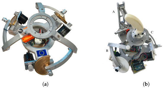
Figure 1.
(a) The 3-RRR Spherical parallel manipulator. (b) The 2RRR-1URU quasi-spherical parallel manipulator (qSPM): the URU leg is labeled as leg A, and the RRR legs as legs B and C.
This article focuses on software control integration and the definition of a hapto-visual digital twin of the quasi-spherical parallel manipulator (qSPM) architecture. The digital twin, defined via the robotic operating system (ROS), works in parallel with the main control loop of the system and ensures the operator haptic and enhanced visual feedback in real-time. The developed digital twin is then used to assist a student operator in reproducing a predefined teaching trajectory and to evaluate training through an assistive control action. The system analyzed in this paper is intended to be one component of a comprehensive architecture, which includes a simulation of the operational environment as part of a broader training program for didactic telesurgery. In fact, this type of procedure aims to eventually address the limitations of traditional training, which often relies heavily on verbal instruction and passive visual observation. This trend has recently begun to receive attention [27,28,29].
2. Materials and Methods
2.1. Kinematic Description, Jacobian, and Haptic Feedback
As stated in Section 1, the qSPM device consists of two spherical RRR legs (leg B and C), and a URU leg (leg A, as in Figure 1b). Kinematic models are delineated and formalized in [23,24,25]. Reporting a nomenclature scheme in Figure 2a for clarity, the following main premises can be outlined ():
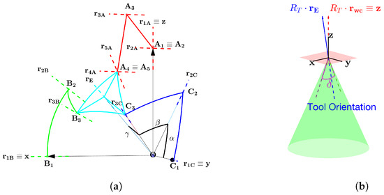
Figure 2.
(a) Schematic representation of the nomenclature of the qSPM device. (b) Operative RCM workspace of the bilaterally teleoperated system. The platform’s orientation is transmitted to the slave’s instrumented tool through a proper rotation matrix .
- We define the origin-based unit vectors as parallel to the axes of the R joints ;
- We define as the unit vector pointing to the platform’s center E. Its orientation is expressed by the Euler angles triplet , as in Equation (1):in which and denote rotation matrices around axes and ;
- We define the workspace center coincident to the bisector of the first octant, as in Equation (2):in which , being a self-rotation angle, we can assume any possible value within the operative workspace , and it is considered zero by default [25];
- According to the superposition principle, U joints on leg A can each be decomposed into two R joints sharing perpendicular axes, namely couples and , as in Figure 2a;
- Considering a symmetrical structure for simplicity, we define the geometrical angles as the ones describing the angular span of proximal links and , distal links and , and angle , respectively;
- As stated in Section 1, joints are each actuated by motors, and their revolution axes are perpendicular. Imposing , , , the actuated angle triplet is ;
- In the bilaterally teleoperated system, the platform’s orientation is transmitted to the slave’s instrumented tool for RCM control and transformed through a proper rotation matrix , as in Figure 2b.
With such formulation, thanks to geometric constructions, we can define the Jacobian J of the device and its dexterity , as in Equations (3) and (4) [23,24,25]:
in which is the parallel Jacobian, is the serial Jacobian, and inscription is the spectral norm.
The Jacobian can be used to define general torque control and haptic feedback for bilateral teleoperation, as in Equation (5) [25].
in which are the active torques acting on the active angles , are the operational torques sensed on the slave robot’s tool to be reproduced through haptic feedback on the master device, are extra control torques directly applied to the master device, and are static compensation torques.
2.2. Inverse and Forward Kinematics, Working Modes, and Self-Collision
IKM and FKM are the functions linking the platform’s orientation to the actuated triplet , respectively, and vice versa. As the IKM function leads to eight different solutions, i.e., working modes , depending on the posture of the legs and on the sign of the elements of the diagonal matrix [30], each FKM can be computed according to the constraints topologically imposed by each working mode. It has been demonstrated that the FKM can be computed with great computational gains by adding an additional encoder sensor on link and thus measuring [24].
In order to compare all possible working modes and choose the best one, the research not only considered by studying parallel and serial singularity but also the possibility of self-collision among the legs and a cylindric volume centered in in anticipation of adding a degree of freedom on the tool’s axial displacement [25].
2.3. Reachable Workspace and Best Working Mode
With the assumptions described in Section 2.2, we can define the reachable workspace as the portion of the operative workspace in the Euler Space connected without discontinuity to the workspace center , i.e., without crossing any singularity area (in which ) or any self-collision area , as in Equation (6) [25].
in which is a random continuous path between point P and the operative workspace center , Equation (2). As and are subjects of the kinematics of the system, the reachable workspace depends on the selected working mode. An example of for , in offset space with respect to central angles Equation (2), is shown in Figure 3a. Due to being a self-rotation angle, the reachable workspace can be analyzed for simplicity by sectioning it on planes , as in Figure 3b and [23,24,25].
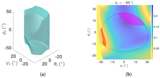
Figure 3.
(a) Reachable workspace inside the Euler space for working mode . (b) A sectioned view of the reachable workspace on plane with : red and purple areas, respectively, correspond to and within the operative workspace , outlined in black; green dots denote the workspace center . A detailed discussion on the workspaces can be found in [25].
Among all possible working modes, it has been demonstrated that , as represented in Figure 1b and Figure 2a, is the best in combined terms of , self-collision among its parts, and operative feasibility, outputting the largest reachable workspace [25]. Therefore, has been chosen as the operative working mode for this study.
2.4. Hapto-Visual Digital Twin for Assistive Control
As the main focus of this study, a hapto-visual digital twin is a detailed simulation model that integrates both haptic feedback and visual representations to provide an immersive and interactive user experience. Implementing a digital twin in the architecture not only allows for more flexible and precise usage of the master device but also introduces a new assistive control mode that implements predefined teaching trajectories for didactic purposes.
In the analyzed environment, a student aims to reproduce a teaching trajectory as closely as possible with the aid of visual and haptic feedback. We define the following sampled trajectories as in Equation (7).
in which we assume, for clarity, notation ; is the sampling index; is the sampling period; is the student trajectory, i.e., the one which is the current output of the FKM function; is the teacher trajectory, i.e., the one which the student aims to follow, predetermined in a stored matrix ; is the k-th line of , storing ; is the rotational matrix related to the Euler angle, as in Equation (1). Details of relevant parameters can be found in Table A1.
2.4.1. Haptic Assistive Control: Premises
In order to implement haptic assistive control to be used in the application described in Section 2.4, we must make the following definitions:
- For clarity of notation, given Equation (7), we define the instantaneous errors between student and teaching trajectories Equation (8):
- We define the time-varying cubic neighborhood as the subdominion of centered in , as in Equation (9a). As a first approach, the self-rotation angle can be neglected, defining the restricted squared neighborhood on plane , as in Equation (9b). All involved parameters’ value definitions can be found in Table A1.
- We finally define, neglecting and according to Equations (8) and (9b), the reduced euclidean distance , lying on the plane, between reduced and , as in Equation (10):
2.4.2. Haptic Assistive Control: Basic Description
With the reduced euclidean distance , we can impose an assistive control action on the system, adjusting the platform orientation angles by pushing the user inside an admitted neighborhood on the basis of a segmented spring-like function, as in Equation (11) and in Figure 4:
in which is a suitable spring constant; is the radius of the force-related admitted area in which no assisted action is required; is the unit vector perpendicular to lying on the plane , according to Equation (12) and Figure 4b; is the platform’s instant angular rotation.
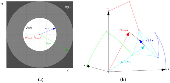
Figure 4.
(a) Restricted neighborhood Equation (9b), colored according to Equation (11): white, grey, and black areas correspond, respectively, to force-related admitted area Equations (11a)–(11c). Red points correspond to the point . (b) Geometrical explanation of vector Equation (12). The vector is not to scale, and was increased for readability.
A similar but more straightforward procedure can be adopted for the self-rotation angle by imposing a segmental spring-like torque around , as in Equation (13):
in which is the torque-related admitted range for in which no assisted action is required; .
Also, taking into account a damping action , which activates if expressions Equations (11) and (13) are non-zero, the device is then subjected to from Equation (5), as in Equation (14).
in which is the actual distance between the platform’s center and the origin.
2.4.3. Haptic Assistive Control: Modifications
Considering the definition of the haptic assistive control made in the previous sections, we have made the following possible modifications:
- (I)
- To have a more fluid assistive action, we can consider not only the current but also for determining a suitable action associated with neighborhood . Admitted dominions should then depend on . The control algorithm can be easily modified between different admitted areas’ shapes by considering discrete numeric maps to apply on instead of analytic functions, as in Equations (11) and (13). Examples on are shown in Figure 5;
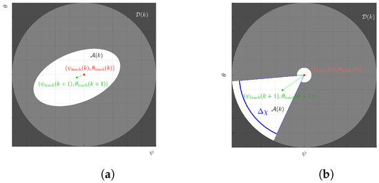 Figure 5. (a) Elliptic admitted area centered in with the major axis parallel to . (b) Sliced admitted area composed of a reduced circular admitted area of span, and a circular sector of angular span with bisection parallel to .
 - (II)
- To have a less stringent and time-based assistive action, we can check whether the student has reached before updating to the next through a boolean condition . In this way, the effects of the control loop are drastically reduced, the performance is not evaluated in a time-based point of view, and the student is assisted only when actively leaves the current admitted dominion . Having adopted this strategy for the experimental part, from this point on the sampling index k will be removed for clarity;
- (III)
- To have an even less timely action, and with the aid of the visual feedback to be presented in Section 2.4.4, can toggle only on a subset of depending on , e.g., on , for a circular , such as the one presented in Figure 5b.
2.4.4. Visual Digital Twin
The visual digital twin aims to visualize on a screen available to the end user the actual pose of the master device. Using the RViz environment inside ROS, each element is processed by a marker object, which contains the following information:
- The 3D mesh model of the object, processed in a digital asset exchange (.dae) format, referenced by a suitable relative reference frame (RF) centered in for all spherical elements (i.e., legs B and C, and platform), for non-spherical elements following the standard Denavit–Hartenberg convention;
- The pose of the object, contained by a quaternion computed from a suitable rotational matrix associated with the object and the relative RF described by the previous point.
The visual environment can be enhanced by adding extra information regarding the pose of the object, for instance, reporting, for the assistive control mode, RFs associated with and according to Equation (7) and Section 2.4.3, and as in Figure 6. In order to enhance the visual feedback, the RF related to , reporting the actual pose of the platform, can be colored in an automatically-updating red/green hue, describing a near (green) or distant (red) from in a way consistent with Equations (11) and (13). In this way, the end user is constantly aware, by looking at the screen, of where the current position of is and how to correct the platform’s pose in order to reach .
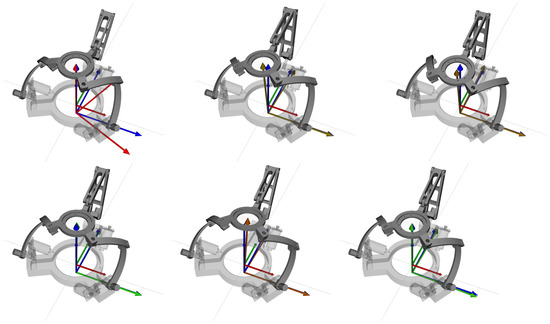
Figure 6.
Different poses of the device in the RViz environment. The visual feedback is enriched by the RFs related to (blue) and (red/green hue) Equation (7).
2.5. Overall Control Scheme Implementation
The software architecture of the prototype was developed inside an ROS environment. The main structure of the system can be summarized by the following blocks reported in the colored areas of Figure 7, each corresponding to single or multiple ROS nodes:
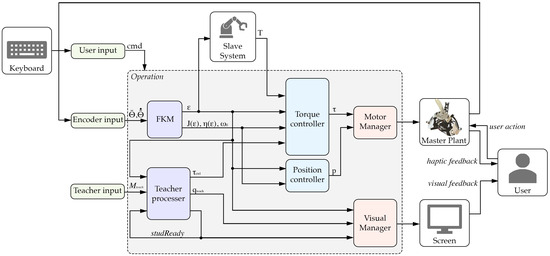
Figure 7.
Schematic architecture of the overall system. The master’s software architecture is highlighted in colored areas, blocks referring to Section 2.5. Since the operating mode signal acts on every block inside the operation subsystem, it was schematized entering said overall subsystem for clarity.
- Input blocks (Light green):
- –
- User input: Allowing an end user to toggle between control modes or shut off the device for emergency purposes via a keyboard. The device’s control modes, each corresponding to a suitable integer value inside topic , include different operational modes of the device: the free roaming and reset modes developed, respectively, in [25,26]; the stop mode, blocking the master device; the bilateral teleoperation mode, in which the operator interacts with a RCM slave device, such as the one described in [31], and receives haptic feedback; the assistive control mode, outlined in Section 2.4, in which the end user aims to follow a predefined path .
- –
- Encoder input: Interfacing with the absolute encoders measuring (MAB18A by Megatron [32], Table A2) through a microcontroller development board (Arduino Uno using Arduino [33]). The block is devoted to the encoders’ signal input and conditioning of , as outlined in Section 2.2. It also contains a signal differentiator to output the joint speed .
- –
- Teacher input: Outputting a predefined teaching path through the matrix , as described in Section 2.4.
- Processing blocks (dark blue):
- –
- FKM: Inputting the measured angles and outputting the estimated values of , , , and , as outlined in Section 2.1 and Section 2.2.
- –
- Teacher processer: Updating the current to feed into the system. The block checks whether has reached the current admitted dominion and updates only when said condition , as described in Section 2.4.3.
- Control blocks (light blue):
- –
- Position controller: Used by control modes such as the reset or stop modes, computing a suitable reference position or joint path.
- –
- Torque controller: Used by control modes such as the free roaming, bilateral teleoperation, or assistive control modes. Its purpose is to process and compute, basing on Equation (5), a suitable torque control input.
- Output blocks (light red):
- –
- Motor manager: Devoted to processing the control inputs and interfacing with the prototype’s motors (SC040B by simplex motion [34], Table A3) via the Minimalmodbus Python module [35].
- –
- Visual manager: For pre-processing and visualizing the visual digital twin inside RViz environement, as described in Section 2.4.4.
The overall control scheme also contains the following additional elements:
- Keyboard input: Allowing the user to switch between different control modes;
- Slave plant: Interacting with the architecture by inputting for RCM position control, and outputting , as in Equation (5);
- Master plant: Detailed in the previous Sections, it allows said haptic feedback to reach the end user;
- Screen output: Allowing visual haptic feedback to reach the user.
2.6. Testing Methods
We report in this section a preliminary testing method related to the device in the assistive control mode, described in Section 2.4 and Section 2.5, adopting the modifications on the haptic assistive control (II) and (III) depicted in Section 2.4.3.
For the experiment, the selected teacher trajectory , stored in a suitable , is reported in Figure 8, and consists of a simple trajectory in which and linearly span and , respectively.

Figure 8.
Selected teacher trajectory reported in the Euler angles .
In the experiment, an end user is tasked with moving the platform through the handle shown in Figure 1b, as to follow trajectory as closely as possible. The following experiments took place:
- (Ex1)
- Four times the assistive control is composed only of Equation (11), neglecting self-rotation outside admitted Equation (13);
- (Ex2)
- One time the end user, not aiming to follow , actively moves the platform outside the admitted , as to prompt , neglecting self-rotation ;
- (Ex3)
- Four times the assistive action is fully implemented, taking into account all Euler angles and the full formula Equation (14).
An additional recording node is added to the control scheme in Figure 7, tasked with the memorization of the following variables:
- The Euler angles triple , related to the student trajectory Equation (7a). The angles are offset to the workspace center Equation (2) for plotting clarity;
- The Euler angles triple , related to the teacher trajectory stored inside (7b). The angles are offset for clarity;
- The elements of the assistive force Equation (11) within the operative RF , defined in Section 2.1;
- The elements of the assistive torque Equation (13);
- The elements of the assistive damping Equation (14).
Other relevant variables and values reported in the results are as follows:
- Variables in Equation (8), described in Section 2.4.1;
- Variable in Equation (10), described in Section 2.4.1;
- Values and , described in Section 2.4.2 and reported in Table A1.
In the testing setup, the student user is first given the opportunity to familiarize themselves with the device in the free roaming mode and are allowed to watch a preview of the teaching path on screen. After resetting the device to the workspace center using the reset mode, the experiments are conducted. Various frames of the testing environment are shown in Figure 9.
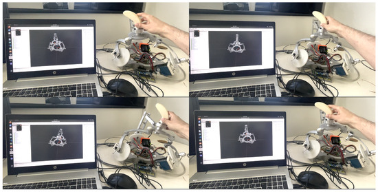
Figure 9.
Testing setup used for the experiments (Ex1), (Ex2) and (Ex3), in which the device is controlled through an ROS environment, as in Section 2.5, and the visual part of the digital twin is generated using RViz, as in Section 2.4.4.
3. Results
3.1. Experiment 1
Since the experiment is not time-based due to (II), only the results of one trial from (Ex1) are reported in Figure 10 for clarity, whereas the others are shown in different subplots in Figure A1.
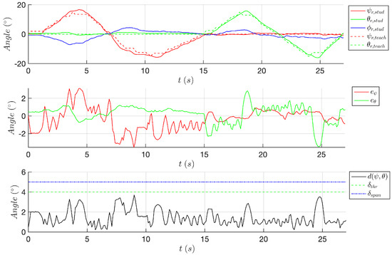
Figure 10.
Time-based plots of the following variables: (top) Euler angles associated with (continuous) and (dashed) in Equation (7); (middle) their differences in Equation (8); (bottom) distance in Equation (10) correlating to the and in Equation (11).
Due to the nature of (Ex1), and are not present. Since remained below for the entire duration of the experiment, the values of in Equation (11) are not reported. The correlation between the two parameters is indeed studied in (Ex2).
3.2. Experiment 2
The results of (Ex2) are reported in Figure 11. Due to the nature of (Ex2), the absolute trajectories of and are omitted for brevity, only reporting differences .
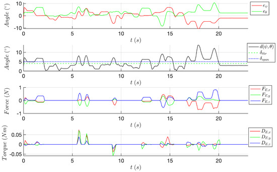
Figure 11.
Time-based plots of the following variables: (top) differences in Equation (8); (middle–top) distance in Equation (10) correlating to and (11); (middle–bottom) elements of Equation (11) within the operative RF; (bottom) elements of in Equation (14) within the operative RF.
3.3. Experiment 3
Similarly to the results of (Ex1), only the results of one trial from (Ex3) are reported in Figure 12 for clarity, whereas the others are shown in different subplots in Figure A2.
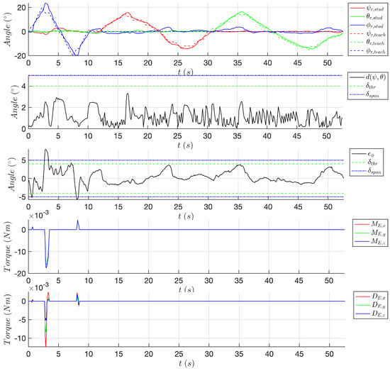
Figure 12.
Time-based plots of the following variables: (top) Euler angles associated with (continuous) and (dashed) in Equation (7); (middle–top) distance in Equation (10) correlating to and in Equation (11); (middle) difference in Equation (8); (middle–bottom) elements of in Equation (13) within the operative RF; (bottom) elements of in Equation (14) within the operative RF.
4. Discussion on the Experimental Results
The results of (Ex1) in Section 3.1 show that, thanks to the implementation of the visual digital twin, as described in Section 2.4.4, and the modifications (II) and (III), Equation (10) always, resulting in Equation (11). The mean and standard deviation values of all relevant parameters in all trials are listed in Table 1. Without actual control of the self-rotation angle , Equations (13) and (14), no assistive control action is present, and the end user can follow the teacher trajectory independently. Even if the primary target of the experiment was not focused on time accuracy, as (II) was adopted and the end user had not received sufficient training on the device, (Ex1) still yielded satisfactory results in terms of overall time duration, being approximately 1.6 times slower than the pre-defined teaching path, which has a total duration of 12.3 s. This outcome preliminarily demonstrates how easy and effective it is to respect the threshold conditions without excessively strict constraints and no assistive control over the self-rotation angle .

Table 1.
The mean and standard deviation of the Euler angles’ instantaneous errors Equation (8) and the reduced euclidean distance Equation (10) in (Ex1), alongside the time durations of each trial. All average values are weighted on the time durations of the trials. Average duration is arithmetic.
Due to the results of (Ex1), the end user was tasked with actively trespassing in (Ex2). The outcome, described in Section 3.2, demonstrates how the control action of indeed respects Equation (11). The assistive control action indeed pushes, with a sufficiently strong but yet to be optimized value, the end user inside the current admitted area outlined by relation with a fitting assistive action. In parts , it is imposed . This is done in order not to trigger, with a narrow , an unwanted and uncontrolled vibrating action between the thresholds of said dominions.
The same experiment of (Ex1) is reproduced in (Ex3) with the addition of an assistive torque action on the self-rotation angle , as in Equation (13). The control action is then assumed in its complete form Equation (14). Similarly to (Ex1), always, there are time intervals in which , issuing , and thus following Equation (13). The assistive control action is thus sufficiently strong to steer the user within the admitted area , allowing for the continuation of the experiment. The mean and standard deviation values ofall relevant parameters involved in the trials are listed in Table 2. The greater amplitude of can be explained by the fact that modification (III) does not account for any simplification on the admitted area , only focusing on . Nevertheless, the overall behavior on the self-rotation is satisfying for these preliminary results, having, for all trials in (Ex3), and a percentage of admitted sampling points of . The average time duration, still considering the caveats of (Ex1), does not seem affected by the full assistive control implementation, being approximately 1.7 times slower than the reference one of 20.3 s, a result comparable to the one obtained in (Ex1).

Table 2.
The mean and standard deviation of the Euler angles’ instantaneous errors Equation (8) and the reduced euclidean distance Equation (10) in (Ex3). The average values are weighted on the time durations of the trials. Average duration is arithmetic.
5. Conclusions
This paper was devoted to the definition and implementation of a hapto-visual digital twin for the quasi-spherical parallel manipulator (qSPM) to be used for assistive control in didactic telesurgery. After outlining the kinematics and reachable workspace of the device, the research presented the formal definition of assistive control, in which a student user is required to follow a predefined teaching trajectory inside relevant threshold parameters. The paper described both the haptic and visual attributes of the digital twin, characterizing their functionalities and presenting possible modifications to make the control algorithm less stringent.
In fact, this approach aimed to overcome both traditional surgical training limitations, heavily relying on verbal instructions and visual observations, enabling stricter “hand-over-hand” guidance methods by allowing the user to take the initiative within an accepted range where no corrective actions are taken by the device.
After presenting the hardware and software implementation of the overall system, preliminary tests were conducted to analyze its performance in an exemplified assistive control environment. Results show the following: assistive control without any intervention on self-rotation angle indeed satisfies all threshold constraints, requiring no control action; said control action is sufficiently strong enough to push the user inside the time-variant admitted area following the teacher trajectory; the full control action on all the platform’s orientation Euler triplet has been deemed satisfactory for this preliminary testing, with a high percentage of admitted sampling points of . Our results further demonstrate how the overall training protocol could support the objective definition of learning curves and lay the foundation for telementorship-based training, overcoming the limitations of traditional training methods in a teleoperation environment.
Future developments will directly involve thorough testing of the assistive control algorithm, revolving around a broader sample of end user subjects and using the device with different and more complex teaching trajectories , ultimately defined through the full use of the bilaterally teleoperated system. The research will also focus on the modifications presented in Section 2.4.3: testing different dominions, as in (I) and (III), and relaxing all the constraints defined in (II) and (III). As the testing results presented are preliminary, the study will involve the optimization of the assistive action control parameters: for the amplitude of the neighborhood dominion and admitted area Equation (9) and for the actual amplitudes of the assistive action forces Equations (11)–(14). This optimization could depend on different discrete “strictness levels” of the control strategy, which may be selected based on the individual end user or the specific current operation of the device.
Author Contributions
Conceptualization, D.P.Q. and M.A.L.; Methodology, D.M. and M.A.L.; Project administration, M.A.L.; Software, D.P.Q.; Supervision, D.M. and M.A.L.; Validation, D.P.Q., D.M. and M.A.L.; Writing—original draft, D.P.Q.; Writing—review and editing, D.M. and M.A.L. All authors have read and agreed to the published version of the manuscript.
Funding
This research received no external funding.
Informed Consent Statement
Informed consent was obtained from all subjects involved in the study.
Data Availability Statement
The original contributions presented in the study are included in the article. Further inquiries can be directed to the corresponding author.
Conflicts of Interest
The authors declare no conflicts of interest.
Abbreviations
The following abbreviations are used in this manuscript:
| R | Rotational Joint |
| U | Universal Joint |
| RF(s) | Reference Frame(s) |
| RCM | Remote Center of Motion |
| qSPM | Quasi-Spherical Parallel Manipulator |
| IKM | Inverse Kinematic Model |
| FKM | Forward Kinematic Model |
| ROS | Robotic Operating System |
Appendix A. Assistive Control Parameters

Table A1.
Assistive control parameters used for the experiments.
Table A1.
Assistive control parameters used for the experiments.
| Parameter | Symbol | Value | Unit |
|---|---|---|---|
| Distance between operative RF origin and platform center | 0.208 | [m] | |
| Sampling Period | 0.01 | [s] | |
| Number of teacher trajectory’s samples | N | 376 | - |
| Neighborhood angular span | 5 | [∘] | |
| Neighborhood angular admissible threshold on | 4 | [∘] | |
| Maximum spring coefficient on reduced distance Equation (10) | 3 | [N/m] | |
| Maximum spring coefficient on self-rotation | 0.1 | [Nm/rad] | |
| Damping coefficient | 1 | [Nms/rad] |
Appendix B. Hardware Specifics

Table A2.
Hall-effect absolute encoder MAB18A using Megatron specifics. More details are reported in [32].
Table A2.
Hall-effect absolute encoder MAB18A using Megatron specifics. More details are reported in [32].
| Specific | Value | Unit |
|---|---|---|
| Angle range | 360 | [∘] |
| Angle resolution | 4096 | steps |
| Supply voltage | 5 | [V] |
| Supply current | <20 | [mA] |
| Signal load | >5 | [] |
| Output voltage range | 0–5 | [V] |

Table A3.
Motor SC040B by Simplex motion specifics. More details are reported in [34].
Table A3.
Motor SC040B by Simplex motion specifics. More details are reported in [34].
| Specific | Value | Unit |
|---|---|---|
| Maximum Speed (@24V) | 6000 | [rpm] |
| Maximum Torque | 0.8 | [Nm] |
| Rated Torque | 0.28 | [Nm] |
| Power supply input voltage | 24 | [V] |
| Maximum continuous mechanical output power | 120 | [W] |
| Gear-ratio (by crafted 3D-printed gears) | 200/23 | - |
Appendix C. Other Results
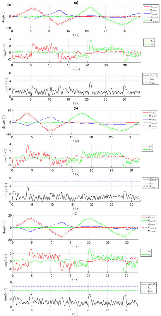
Figure A1.
Other results of (Ex1) (a–c): time-based plots of the following variables: (top) Euler angles associated with (continuous) and (dashed) Equation (7); (middle) their differences Equation (8); (bottom) distance Equation (10) correlating with and Equation (11).
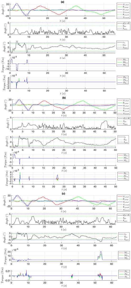
Figure A2.
Other results of 3 (a–c): time-based plots of the following variables: (top) differences (8); (middle–top) distance Equation (10) in correlation of and Equation (11); (middle–bottom) elements of Equation (11) within the operative RF; (bottom) elements of Equation (14) within the operative RF.
References
- Hokayem, P.F.; Spong, M.W. Bilateral teleoperation, An historical survey. Automatica 2006, 42, 2035–2057. [Google Scholar] [CrossRef]
- Goertz, R.C. Remote-Control Manipulator. U.S. Patent US2632574A, 24 March 1953. [Google Scholar]
- Bolopion, A.; Régnier, S. A Review of Haptic Feedback Teleoperation Systems for Micromanipulation and Microassembly. IEEE Trans. Autom. Sci. Eng. 2013, 10, 496–502. [Google Scholar] [CrossRef]
- Bayraktaroglu, Z.; Argin, O.; Haliyo, S. A modular bilateral haptic control framework for teleoperation of robots. Robotica 2019, 37, 338–357. [Google Scholar] [CrossRef]
- Jakuba, M.V.; German, C.R.; Bowen, A.D.; Whitcomb, L.L.; Hand, K.; Branch, A.; Chien, S.; McFarland, C. Teleoperation and robotics under ice, Implications for planetary exploration. In Proceedings of the 2018 IEEE Aerospace Conference, Big Sky, MT, USA, 3–10 March 2018; pp. 1–14. [Google Scholar]
- Imaida, T.; Yokokohji, Y.; Doi, T.; Oda, M.; Yoshikawa, T. Ground-space bilateral teleoperation of ETS-VII robot arm by direct bilateral coupling under 7-s time delay condition. IEEE Trans. Robot. 2004, 20, 499–511. [Google Scholar] [CrossRef]
- Evans, C.R.; Medina, M.G.; Dwyer, A.M. Telemedicine and telerobotics, from science fiction to reality. Updates Surg. 2018, 70, 357–362. [Google Scholar] [CrossRef] [PubMed]
- Joshi, S.D. Smart Factory Digital Twin for Performance Measurement, Optimization, and Prediction. In Transforming Industry Using Digital Twin Technology; Mishra, A., El Barachi, M., Kumar, M., Eds.; Springer: Cham, Switzerland, 2024; pp. 115–143. [Google Scholar]
- Fan, W.; Guo, X.; Feng, E.; Lin, J.; Wang, Y.; Liang, J.; Garrad, M.; Rossiter, J.; Zhang, Z.; Lepora, N.; et al. Digital Twin-Driven Mixed Reality Framework for Immersive Teleoperation With Haptic Renderin. IEEE Robot. Auto. Lett. 2023, 8, 8494–8501. [Google Scholar] [CrossRef]
- Lopez Pulgarin, E.J.; Niu, H.; Herrmann, G.; Carrasco, J. Implementing and Assessing a Remote Teleoperation Setup with a Digital Twin Using Cloud Networking. In Towards Autonomous Robotic Systems; Cryer, A., Tugal, H., Caliskanelli, I., Pacheco-Gutierrez, S., Skilton, R., Eds.; Springer: Cham, Switzerland, 2022; pp. 238–250. [Google Scholar]
- Tiwari, S.; Shukla, A. Digital Twins in Industry: Real-World Applications and Innovations In Transforming Industry Using Digital Twin Technology; Mishra, A., El Barachi, M., Kumar, M., Eds.; Springer: Cham, Switzerland, 2024; pp. 1–18. [Google Scholar]
- Fuller, A.; Fan, Z.; Day, C.; Barlow, C. Digital Twin: Enabling Technologies, Challenges and Open Research. IEEE Access 2020, 8, 108952–108971. [Google Scholar] [CrossRef]
- Bofill, J.; Abisado, M.; Villaverde, J.; Sampedro, G.A. Exploring Digital Twin-Based Fault Monitoring: Challenges and Opportunities. Sensors 2023, 23, 7087. [Google Scholar] [CrossRef]
- Choi, P.J.; Oskouian, R.J.; Tubbs, R.S. Telesurgery, Past, Present, and Future. Cureus 2018, 10, e2716. [Google Scholar] [CrossRef]
- Barba, P.; Stramiello, J.; Funk, E.K.; Richter, F.; Yip, M.C.; Orosco, R.K. Remote telesurgery in humans, a systematic review. Surg. Endosc. 2022, 36, 2771–2777. [Google Scholar] [CrossRef]
- Satcher, R.L.; Bogler, O.; Hyle, L.; Lee, A.; Simmons, A.; Williams, R.; Hawk, E.; Matin, S.; Brewster, A.M. Telemedicine and telesurgery in cancer care, Inaugural conference at MD Anderson Cancer Center. J. Surg. Oncol. 2014, 110, 353–359. [Google Scholar] [CrossRef] [PubMed]
- Rovetta, A.; Sala, R.; Wen, X.; Cosmi, F.; Togno, A.; Milanesi, S. Telerobotic surgery project for laparoscopy. Robotica 1995, 13, 397–400. [Google Scholar] [CrossRef]
- Meskini, M.; Saafi, H.; Mlika, A.; Arsicault, M.; Zeghloul, S.; Laribi, M.A. Development of a novel hybrid haptic (nHH) device with a remote center of rotation dedicated to laparoscopic surgery. Robotica 2023, 41, 3175–3194. [Google Scholar] [CrossRef]
- Tian, W.; Fan, M.; Zeng, C.; Liu, Y.; He, D.; Zhang, Q. Telerobotic Spinal Surgery Based on 5G Network, The First 12 Cases. Neurospine 2020, 17, 114–120. [Google Scholar] [CrossRef] [PubMed]
- Lopez, I.B.; Benzakour, A.; Mavrogenis, A.; Benzakour, T.; Ahmad, A.; Lemée, J.M. Robotics in spine surgery, systematic review of literature. Int. Orthop. 2023, 47, 447–456. [Google Scholar] [CrossRef]
- Saafi, H.; Laribi, M.A.; Zeghloul, S. Improvement of the direct kinematic model of a haptic device for medical application in real time using an extra sensor. In Proceedings of the 2014 IEEE/RSJ International Conference on Intelligent Robots and Systems, Chicago, IL, USA, 14–18 September 2014; pp. 1697–1702. [Google Scholar]
- Saafi, H.; Laribi, M.A.; Zeghloul, S. Redundantly actuated 3-RRR spherical parallel manipulator used as a haptic device, Improving dexterity and eliminating singularity. Robotica 2015, 33, 1113–1130. [Google Scholar] [CrossRef]
- Saafi, H.; Zeghloul, S.; Arsicault, M.; Laribi, M.A. On the Development of a New Master Device Used for Medical Tasks. J. Mech. Robot. 2018, 10, 044501. [Google Scholar] [CrossRef]
- Saafi, H.; Laribi, M.A.; Zeghloul, S. Forward Kinematic Model Resolution of a Special Spherical Parallel Manipulator: Comparison and Real-Time Validation. Robotics 2020, 9, 62. [Google Scholar] [CrossRef]
- Pacheco Quiñones, D.; Maffiodo, D.; Laribi, M.A. Kinematic Analysis, Workspace definition and Self-Collision avoidance of a quasi-Spherical Parallel Manipulator. Robotica 2025. accepted. [Google Scholar]
- Pacheco Quiñones, D.; Maffiodo, D.; Laribi, M.A. Joint Path Planning of the Quasi-Spherical Parallel Manipulator. In Advances in Italian Mechanism Science; Quaglia, G., Boschetti, G., Carbone, G., Eds.; Springer: Cham, Switzerland, 2024; pp. 242–248. [Google Scholar]
- Singh, S.K.; Yang, L.; Ma, H. Recent Challenges for Haptic Interface and Control for Robotic Assisted Surgical Training System: A Review. In Proceedings of the 2021 IEEE World AI IoT Congress (AIIoT), Seattle, WA, USA, 10–13 May 2021; pp. 0240–0249. [Google Scholar]
- Garudeswaran, S.; Cho, S.; Ohu, I.; Panahi, A.K.; Kavic, S. Teach and Playback Training Device for Minimally Invasive Surgery. Minim. Invasive Surg. 2018, 2018, 4815761. [Google Scholar] [CrossRef]
- Hong, K.; Sun, Y.; He, J.; Lei, Y.; Yang, L. Preliminary design of a robotic system for kinaesthetic training of surgical tasks. J. Eng. 2019, 2019, 490–494. [Google Scholar] [CrossRef]
- Chablat, D.; Wenger, P. Working modes and aspects in fully parallel manipulators. In Proceedings of the 1998 IEEE International Conference on Robotics and Automation, Leuven, Belgium, 20 May 1998; pp. 1964–1969. [Google Scholar]
- Trabelsi, A.; Sandoval, J.; Mlika, A.; Lahouar, S.; Zeghloul, S.; Cau, J.; Laribi, M.A. Optimal Multi-robot Placement Based on Capability Map for Medical Applications. In Advances in Service and Industrial Robotics; Müller, A., Brandstötter, M., Eds.; Springer: Cham, Switzerland, 2022; Volume 120, pp. 120–135. [Google Scholar]
- Megatron Hall-Effect Absolute Encoder Series MAB18A. Available online: https://www.megatron.de/en/products/more-products-angle-sensors/Hall-effect-absolute-encoder-series-mab18a.html (accessed on 8 June 2024).
- Arduino Uno Board. Available online: https://store.arduino.cc/products/arduino-uno-rev3 (accessed on 8 June 2024).
- Simplex Motion SC-Series. Available online: https://simplexmotion.com/integrated-servomotors/sc-series/ (accessed on 8 June 2024).
- Minimalmodbus Python Module. Available online: https://minimalmodbus.readthedocs.io/en/stable/ (accessed on 8 June 2024).
Disclaimer/Publisher’s Note: The statements, opinions and data contained in all publications are solely those of the individual author(s) and contributor(s) and not of MDPI and/or the editor(s). MDPI and/or the editor(s) disclaim responsibility for any injury to people or property resulting from any ideas, methods, instructions or products referred to in the content. |
© 2024 by the authors. Licensee MDPI, Basel, Switzerland. This article is an open access article distributed under the terms and conditions of the Creative Commons Attribution (CC BY) license (https://creativecommons.org/licenses/by/4.0/).