Article

Applying Screw Theory to Design the Turmell-Bot: A Cable-Driven, Reconfigurable Ankle Rehabilitation Parallel Robot

by
Julio Vargas-Riaño
1,*,
Óscar Agudelo-Varela
2,† and
Ángel Valera
1,†
1
Instituto Universitario de Automática e Informática Industrial (Instituto ai2), Universitat Politècnica de València, 46022 Valencia, Spain
2
Facultad de Ciencias Básicas e Ingeniería, Universidad de los Llanos, Villavicencio 500002, Colombia
*
Author to whom correspondence should be addressed.
These authors contributed equally to this work.
Robotics 2023, 12(6), 154; https://doi.org/10.3390/robotics12060154
Submission received: 30 September 2023 / Revised: 6 November 2023 / Accepted: 11 November 2023 / Published: 14 November 2023
(This article belongs to the Special Issue Kinematics and Robot Design VI, KaRD2023)

Abstract

:
The ankle is a complex joint with a high injury incidence. Rehabilitation Robotics applied to the ankle is a very active research field. We present the kinematics and statics of a cable-driven reconfigurable ankle rehabilitation robot. First, we studied how the tendons pull mid-foot bones around the talocrural and subtalar axes. We proposed a hybrid serial-parallel mechanism analogous to the ankle. Then, using screw theory, we synthesized a cable-driven robot with the human ankle in the closed-loop kinematics. We incorporated a draw-wire sensor to measure the axes’ pose and compute the product of exponentials. We also reconfigured the cables to balance the tension and pressure forces using the axis projection on the base and platform planes. Furthermore, we computed the workspace to show that the reconfigurable design fits several sizes. The data used are from anthropometry and statistics. Finally, we validated the robot’s statics with MuJoCo for various cable length groups corresponding to the axes’ range of motion. We suggested a platform adjusting system and an alignment method. The design is lightweight, and the cable-driven robot has advantages over rigid parallel robots, such as Stewart platforms. We will use compliant actuators for enhancing human–robot interaction.

1. Introduction

Over the past few years, there has been a significant expansion in the domains where robotics is employed. Beyond the conventional industrial applications such as material handling, welding, and machine tending, contemporary robotics finds its way into diverse sectors such as the construction sector [1], rescue robotics [2], agricultural [3,4] and food industry [5], waste management [6], entertainment [7], security systems [8], etc.
The medical field is another sector where there is a significant increase of the use of robots, such as robotic-assisted surgery [9], nurse care [10,11], or rehabilitation robots [12]. In the case of rehabilitation robots, the aim is to develop a system that improves the effectiveness of therapies and the facilitation of patients’ daily routines and exercises. Therefore, rehabilitation robotics can be considered to a collaborative platform, uniting experts in human–robot interaction and biomedical engineering with clinicians and therapists. This synergy aims to create the essential technologies that can enhance the quality of life for patients. This work deals with the design of a ankle rehabilitation robot. Ankle injuries are prevalent in both sports and daily activities, making them among the most frequently occurring injuries. However, to aid in the recovery process, it is imperative for patients to engage in a regimen of rehabilitation exercises. These exercises are typically overseen by a therapist, aiming to strengthen the patient’s ankle joint and restore its full range of motion. In an effort to ease the workload of therapists, allowing them to assist a larger number of patients in a more efficient and secure manner, different lower limb devices have been developing [13].
Designing an ankle rehabilitation device that can accommodate a large percentage of the population is challenging because its size varies depending on several factors, including sex, age, and phenotype. In addition, there is a lack of affordable motion-capture systems and databases for estimating ankle joint models, which makes it complex to develop effective rehabilitation techniques for ankle injuries.
Most ankle rehabilitation devices are for gait rehabilitation or the entire lower limb, including the hip, knee, ankle, and foot [14,15,16,17,18]. As a result, there is a need for more specialized devices that target the ankle joint specifically, and also a need for rehabilitation robotics that increasingly try to adapt the specific needs of patients.
This paper presents a data-driven design method that utilizes population statistics, body proportions, and anthropometry. The design is ideal for low-income countries because we can resize the 3D-printed parts by changing a few parameters. Our purpose is to use a method to easily create a resizable and reconfigurable device that can aid in the movement of the human ankle joint by restoring its range of motion.
None of the existing research focuses on developing a patient-specific ankle model for use when the patient is sitting or lying down. To address this gap-research, we propose a design method for building an affordable, reconfigurable, portable, and 3D scalable device for patients in sitting or lying positions. Instead of using a fixed device, we propose a design method for sizes depending on the target population statistics. For this reason, we created a Jupyter Notebook and put the designs on repositories for the public domain.
In this work, we have taken a human-centered approach. We propose an adjustable device for different foot sizes and be able to switch between limbs. The design is for the patients in lying down positions. Our approach is bioinspired by mimicking the tendons involved in ankle movements while avoiding any forces that could pull the foot away from the ankle. We propose reciprocal tendons that apply pressure against the plantar surface of the foot, which will induce ankle joint integration forces to generate motion. The final design is presented in this article, while the intermediate results can be found in the supplementary materials.
Instead of providing a count for the number of academic database hits, we have included the fundamental kinematics and robot design sources related to screw theory that we consulted, as well as the cited literature on ankle anatomy [19,20,21], where we found inspiration to create our design. We firmly believe that comprehending ankle biomechanics requires these references. Seminal works presenting the ankle model as a parallel mechanism were inspirational for our work [22]. We have developed a unique research approach that utilizes concepts such as screws, Plucker coordinates, and the product of exponentials from screw theory studied in [23,24,25,26]. We sought out works about lower-mobility parallel mechanisms [27,28]. Additionally, we used an approximated patient-specific ankle model to reconfigure the device. Our approach differs from existing patient-specific reconfigurable cable-driven ankle rehabilitation robots for laying/sitting positions. Thus, it may not be easy to compare our work with others in the field. In light of this, we searched for publications on ankle rehabilitation robots to gain a better understanding of the current state of the art. Our work is related to kinematics and robot design [29,30,31,32], and is an application for medical and service robots [33,34,35,36,37,38]. Cable-driven robotics is a trending topic research that is closely related to our work [39,40,41,42,43,44,45]. Screw theory has been applied to performance evaluation in cable-driven parallel robots [46]. In this work, we deal with a reconfigurable low-mobility mechanism 4P-2R. A kind of lower-mobility mechanism was also studied in [47,48]. The screw theory has also been applied to computing rotation centers in [49], and we used the screw theory approach applied to kinematics and statics. We also applied direct kinematics, but there are alternative methods [50]. Our work is related to robotics in rehabilitation. There are application for upper limbs [51,52,53], also using cable-driven actuators [54], and for lower and upper limbs [55]. We focus on the ankle, but other works included the complete lower limbs [56,57]. These can use exoskeletons applied in motion assistance [58], walking assistance [59], and for variable force resistance [60]. A design and performance analysis is in [61]. We found work related to our cable-driven serial chain approach analysis [62].

Related Work

We found ankle rehabilitation robots characterized by degrees of freedom and their chains. For example, a serial robot has been used for ankle rehabilitation [63]. A great number of robots use rigid kinematic chains. One of the first robots was a Stewart platform [64], which is a rigid robot with 6 DoF. Other examples are a 3-RUS/RRR [65], a redundantly actuated mechanism [66], a 3-prismatic-revolute-spherical ankle rehabilitation robot [67], a 3-PRS Parallel Robot [68], a 2-UPS/RRR ankle rehabilitation [69], a nonredundant parallel robot [70], a2-dof turntable [71], and a 2PSS platform [72]. Another approach is the use of pneumatic actuators configured as a 2-SPS Mechanism [73] and pneumatic artificial muscles [74,75,76]. Another alternative is a cable-driven lower-limb parallel robot [77]—optimization methods are in [78], and an innovative robot is in [79]. The most similar to our approach with four wires attached to the shank are in [80], and the CABLEankle [81]. They are designed for the plantar surface of the foot parallel to the transversal plane. As a conclusion, our design is the one designed with four cables, which are reconfigurable and ajustable and can be used in laying positions.

2. Materials and Methods

First, we studied the ankle anatomy in [19] and the International Society of Biomechanics (ISB) [20]. Following that, we used the open-source digital model (z-anatomy) [21] to identify the bones, insertions, tendons, and muscles related to the ankle movement. We introduced the dimensions and geometrical model in a Jupyter Notebook using a SageMath 10 kernel [82] in [83]. We provided the CAD model in [84] and the sources in GitHub [85]. We identified the tendons involved in ankle movement acting as an over-actuated bio-mechanism (two degrees-of-freedom and four tendon groups). Following that, we chose antagonistic tendon groups. We identified the pressure forces from the platform against the plantar surface of the foot. Next, we drew a schematic with the tension forces between the base attached to the shank and a platform attached to the foot. We adapted the robot dimensions from [86], the proportions from [87], and the statistical data from [88]. We start the design by analyzing a simple cable-driven two-axis serial chain, which helps us to understand the reciprocal products between the cable and axis screw representations. We created artificial data from the ankle model using the forward kinematics computed from the “product of exponentials” (PoE). The data serve us to validate how to get the ankle model in practice from trajectory measurements received from a modification of the Turmell-Meter system [89]. When synthesizing the robot, we enlarged the device size to prevent cable contact with the body from the platform and base. We analyzed the cable-driven antagonistic actuation in the perpendicular axes model and used it for the initial calibration. Afterwards, we propose a method for the robot reconfiguration, the workspace, and the static simulation using MuJoCo 2.3.1 [90] to validate the stability by changing the axis and tendon positions. Finally, we proposed a CAD model using SolidWorks 2022.

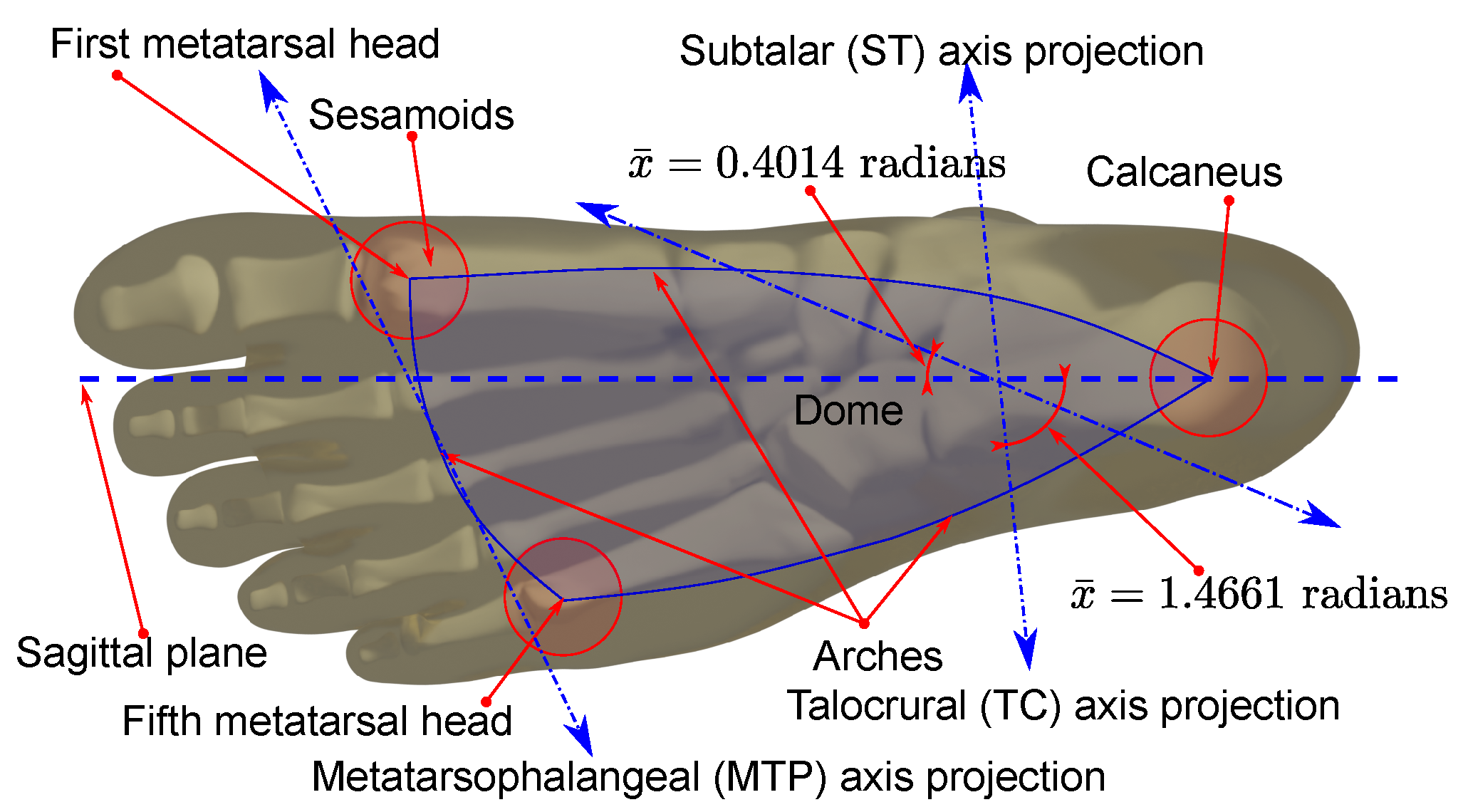
2.1. Robot Inspired on the Analysis of the Ankle Joint

The model has two rotational joints and four tendons involved in ankle movement. First, we analyzed the tension forces and then the compression forces. Finally, we proposed a simplified schematic for the robot.

2.1.1. Ankle-Foot Tendons

The two-axis representation and the tendon insertions in the bones at the mid-foot are in Figure 1. Figure 1a illustrates the main tendons from the lateral-anterior view of the right foot. As we show in Figure 1a, the fifth metatarsal has two insertions, the peroneus tertius, with components for dorsiflexion and eversion, and the peroneus brevis, for eversion and plantarflexion. The calcaneus has the insertion of the Achilles tendon for inversion and plantarflexion. In Figure 1b, we show the medial-bottom view of the foot, and the insertion points are between the first metatarsal and the medial cuneiform. The tibialis anterior contributes to inversion and dorsiflexion, the peroneus longus contributes to plantar flexion and eversion, and the tibialis posterior contributes to inversion and plantar flexion.

2.1.2. Foot Compression Forces

Some requirements for ankle rehabilitation are security and comfort. The foot supports high compression forces in some regions of the plantar surface. In contrast, the dorsal skin is thin, soft, and less tolerant of compression forces. We propose a device that mainly applies pressure at the plantar surface to integrate the ankle joint and generate motion. From the bottom view of the foot, we note that the pressure points are involved in the subtalar and talocrural axes motion. Figure 2 shows the axes projection and the triangle vertices of the transversal plane. The three main points are the tubercle of the calcaneus and the first and fifth metatarsal heads. The pressure points are the projection of the triangular-shaped dome, limited by the lateral, medial-longitudinal arches, and the anterior transverse arch. These contact points transmit a compression force to the platform.

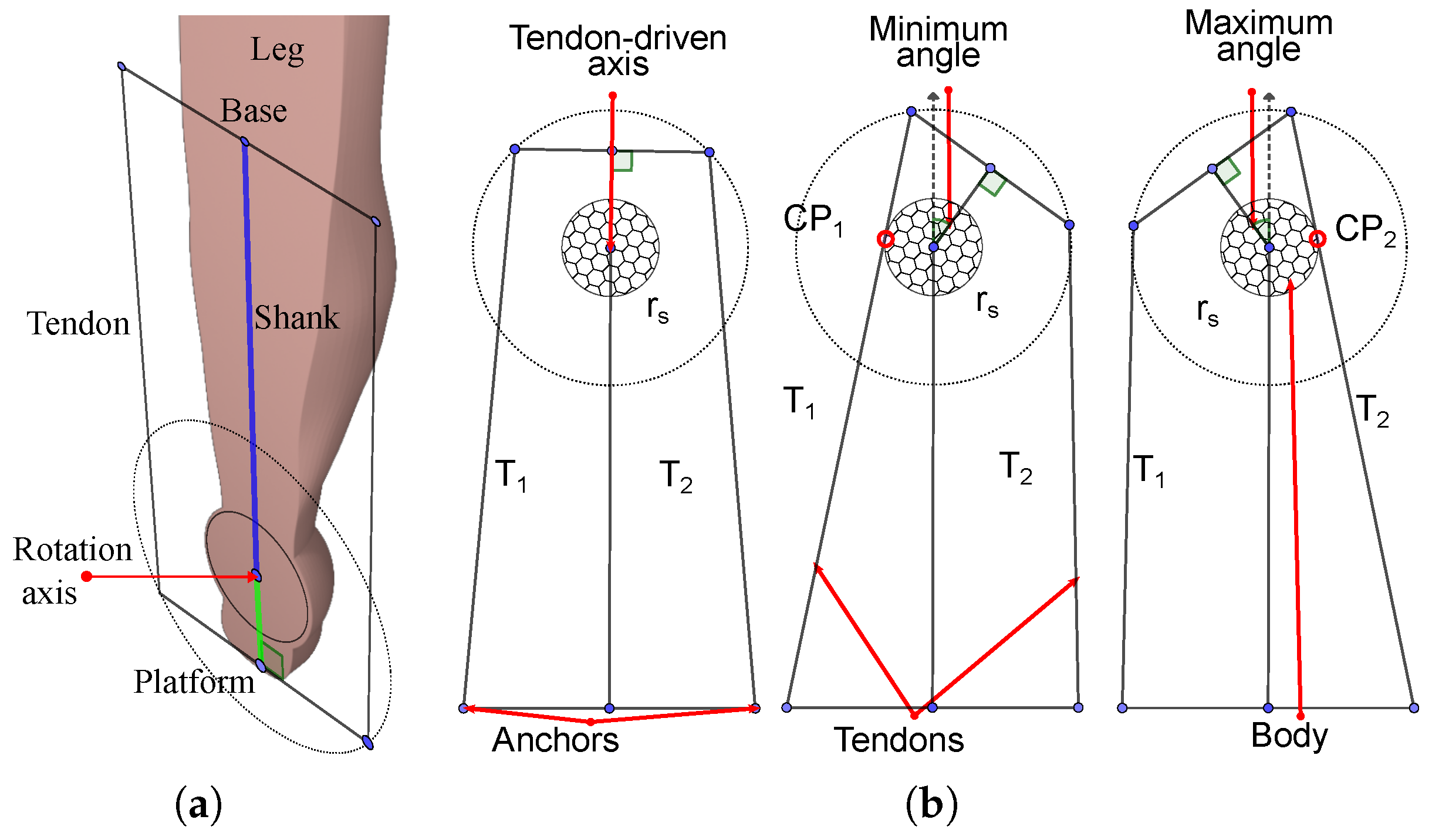
2.1.3. Robot Based on the Ankle-Foot Model

We designed a reconfigurable cable-driven robot to actuate on synergy with the ankle tendons. Cables from the base pull the platform attached to the foot. The cable anchor points have a relocation mechanism to equilibrate the rotation forces on the ankle joint. We aligned the centers to the ankle axes’ intersection on the transverse plane. We show the schematic design in Figure 3. In Figure 3a, we sketch the approximated schematic and show the tendon directions regarding the subtalar (ST) and the talocrural (TC) axis. We represent the foot platform with a circle with a radius r p , centered on P M 0 , and on the same plane of the anchor points a p 1 , a p 2 , a p 3 , and a p 4 . The base is a circle with a radius r b in the same plane as P O , and the anchor points a b 1 , a b 2 , a b 3 , and a b 4 . We simplified the plantar surface of the foot with three contact points f s 1 , f s 2 , and f s 3 . Finally, T 1 , T 2 , T 3 , and T 4 are tendons. The serial kinematic chain is RR, starting at the origin P O , followed by a rotational joint at r 1 on the TC axis, followed by the r 1 r 2 link to a rotational joint at r 2 on the ST axis. A link from r 2 to P M 0 connects the platform with the ankle. The tendons from a p 1 , a p 2 , a p 3 , and a p 4 on the platform to the corresponding a b 1 , a b 2 , a b 3 , and a b 4 on the platform complete the parallel closed-loop structure. Each human ankle has different axis positions; thus, we propose reconfigurable cable attachments. In Figure 3b, the green arrows illustrate the concept of reconfiguration for the right foot by displacing the anchor endpoints a p 1 , a p 2 , a p 3 , and a p 4 on the platform and the anchors a b 1 , a b 2 , a b 3 , and a b 4 on the base. We designed a mechanism for centering pivot points P p b and P p p .
We computed the center points from the intersection of the talocrural and subtalar axes projected on the transverse plane parallel to the base and the platform. Such pivot points are not the same as P 0 and P M 0 , which pertain to the position sensors reference system.

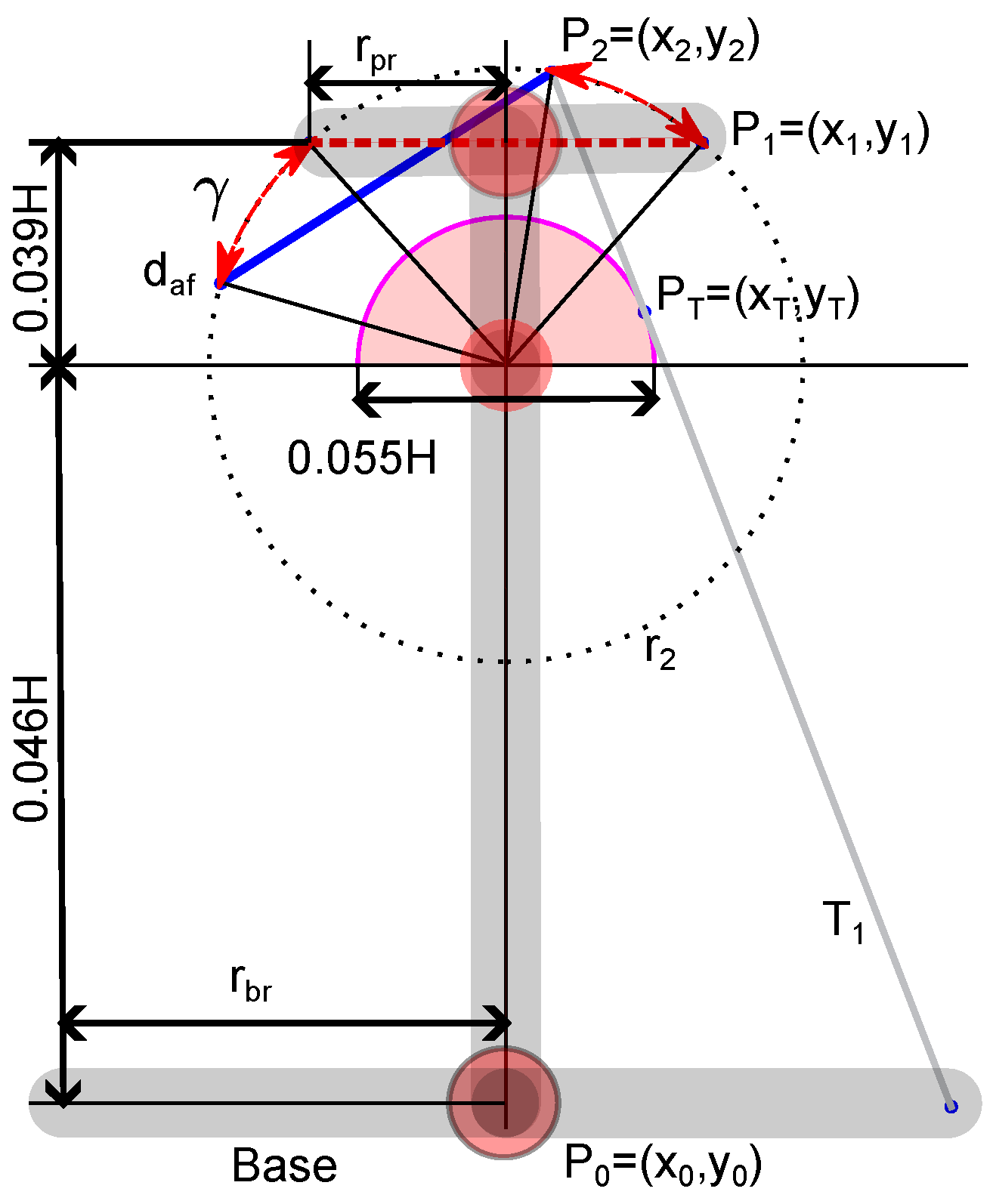
2.1.4. Dimensions and Initial Configuration

In this section, we estimate the initial robot size and configuration. We used the ankle model and measurements from [86], human proportions from [87], and statistical data from [88]. We show the lower limb proportions in Figure 4a. The TC axis is dominant, and we use its statistical value for the cable-body collision analysis. We simplified the body as a sphere centered in half of the ankle’s most medial point (MMP) and most lateral point (MLP); between the two malleoli. We compared this dimension with a leg model in the Figure 4b, illustrating the distance between the ankle and PM on the platform. Additionally, we show that the cables must not be in contact with the foot or the malleolus. The sphere represents the radius between the ankle and the plantar surface of the foot.

2.2. Ankle Kinematic Model

For the ankle kinematics representation, we used data from a two-axis model representation of the ankle joint explained in [89]. There, we described a system for platform pose capture and a method for model approximation using circle fitting, and Figure 5 shows the concept.
The points M 1 , M 2 , and r 1 are references on the talocrural axis. Similarly, N 1 , N 2 , and r 2 are in the subtalar axis. We used it to compute the following vectors and matrices:
r 1 ^ = r 1 P O , r 2 ^ = r 2 P O
ω ^ 1 = M 2 M 1 M 2 M 1 , ω ^ 2 = N 2 N 1 N 2 N 1
ν ^ 1 = ω ^ 1 × r ^ 1 , ν ^ 2 = ω ^ 2 × r ^ 2
ω ^ 1 = ( ω 1 x , ω 1 y , ω 1 z ) , Ω 1 = 0 ω 1 z ω 1 y ω 1 z 0 ω 1 x ω 1 y ω 1 x 0
ω ^ 2 = ( ω 2 x , ω 2 y , ω 2 z ) , Ω 2 = 0 ω 2 z ω 2 y ω 2 z 0 ω 2 x ω 2 y ω 2 x 0
ξ 1 = ν ^ 1 ω ^ 1 , ξ 2 = ν ^ 2 ω ^ 2
Next, we computed the Rodrigues’ formulas:
e ω ^ 1 θ 1 = I 3 × 3 + Ω 1 θ 2 + Ω 1 2 1 cos θ 1
e ω ^ 2 θ 2 = I 3 × 3 + Ω 2 θ 2 + Ω 2 2 1 cos θ 2
representing the θ 1 and θ 2 rotations about ω ^ 1 and ω ^ 2 , respectively. Also, we computed the matrices:
e ξ ^ 1 θ 1 = e ω ^ 1 θ 1 τ ^ 1 0 1 × 3 1 , e ξ ^ 2 θ 2 = e ω ^ 2 θ 2 τ ^ 2 0 1 × 3 1
where:
τ ^ 1 = I 3 × 3 e ω ^ 1 θ 1 ω ^ 1 × ν ^ 1 + ω ^ 1 · ω ^ 1 T ν ^ 1 θ 1
τ ^ 2 = I 3 × 3 e ω ^ 2 θ 2 ω ^ 2 × ν ^ 2 + ω ^ 2 · ω ^ 2 T ν ^ 2 θ 2
If we define the initial pose representation as:
g P ( 0 ) = R 0 P 0 0 1 × 3 1
where:
R 0 = s ^ 0 n ^ 0 a ^ 0
where each column vector is:
s ^ 0 = B 0 + C 0 2 A 0 B 0 + C 0 2 A 0
n ^ 0 = ( B 0 A 0 ) × ( C 0 A 0 ) ( B 0 A 0 ) × ( C 0 A 0 )
a ^ 0 = s ^ 0 × n ^ 0
Then, we finally obtain the product of exponentials (PoE) representation for the serial chain with two hinge joints for all the P points on the platform:
g P = e ξ ^ 1 θ 1 e ξ ^ 2 θ 2 g P ( 0 ) = R T τ T 0 1 × 3 1
where R T is the total rotation matrix and τ T is the total translation vector. The model formulas are in the Supplementary Materials Section S1.1.

2.3. Synthesis of the Parallel Tendon-Driven Robot

The cables must not be in contact with the body and must be smaller than the base and platform used by the draw-wire sensors. To simplify the collision study, we analyzed a coronal section of the foot and ankle, and the contact body is a circle containing the ankle, as illustrated in Figure 6a. We used this coronal section to approximate the platform and base sizes. In Figure 6b, two tendons drive a hinge joint, and the platform anchor points trace two concentric circular trajectories. The segments T 1 and T 2 represent two antagonistic tendons, r s is the radius of a solid body containing the axis of rotation, and the interior circle represents a solid body. The collision contact of the cable with the body depends on the base and platform proportions and the radius r s . By observing this, we note that if the base is larger than the platform, we can enhance the range of motion of the hinge joint. The points M 1 , M 2 , and r 1 are references on the talocrural axis. Similarly, N 1 , N 2 , and r 2 are in the subtalar axis.
We used this coronal section to approximate the platform and base sizes. From the initial position, we defined a maximum and minimum reached angle. The limits are due to collision between the cables and the base body. When T 1 is extending and T 2 is contracting, Tendon T 1 touches the foot in C P 1 . The minimum angle is limited for such a collision. The maximum angle occurs when T 1 is contracting and T 2 is extending. We selected a radius r s greater than the foot width, and then we evaluated a platform radius r p greater than the radius. By selecting a base radius r b , we can evaluate the range of movement. The positive arc and its derivative are:
y = r s 2 x 2
y x = x r s 2 x 2
The derivative is the slope of the line T 1 in the tangent point P T :
x r s 2 x 2 = y y 0 x x 0 ,
solving for y yields:
y = x 2 x · x 0 r s 2 x 2 · y 0 r s 2 x 2
We found the tangential point by substituting y from Equation (18) in Equation (21), yielding the Equation (22).
r s 2 x T 2 = x T 2 x T · x 0 r s 2 x T 2 · y 0 r s 2 x T 2 ,
and simplifying yields (23).
x T · x 0 ( r 2 r s 2 x T 2 · y 0 ) = 0
To solve for x T , we used the software SageMath 10.0. Following that, we replaced the positive value in Equation (18) to find y T . Finally, we found the intersection P 2 with the circular trajectory that has a radius r 2 . To solve for x 2 , we used the following equation:
y T y 0 x T x 0 ( x 2 x 0 ) + y 0 = r 2 2 x 2 2
We found y 2 by replacing x 2 in Equation (18).
To find the arch length, we considered the initial position of anchor point P 1 on the platform. We used the following Equation:
d a f = r 2 2 x 1 2
where d a f is the length from the circle center to the platform central point and defines the trajectory radius regarding the positive semicircle. We solve for x 1 yields two values. By selecting the positive value, we obtain y 1 = d a f . The arc length is given by the absolute difference of the two corresponding angles. We computed the angles by using the Equation:
γ = | arctan 2 y 2 , x 2 arctan 2 y 1 , x 1 |
In Figure 7, we illustrate the full range of motion of the platform.

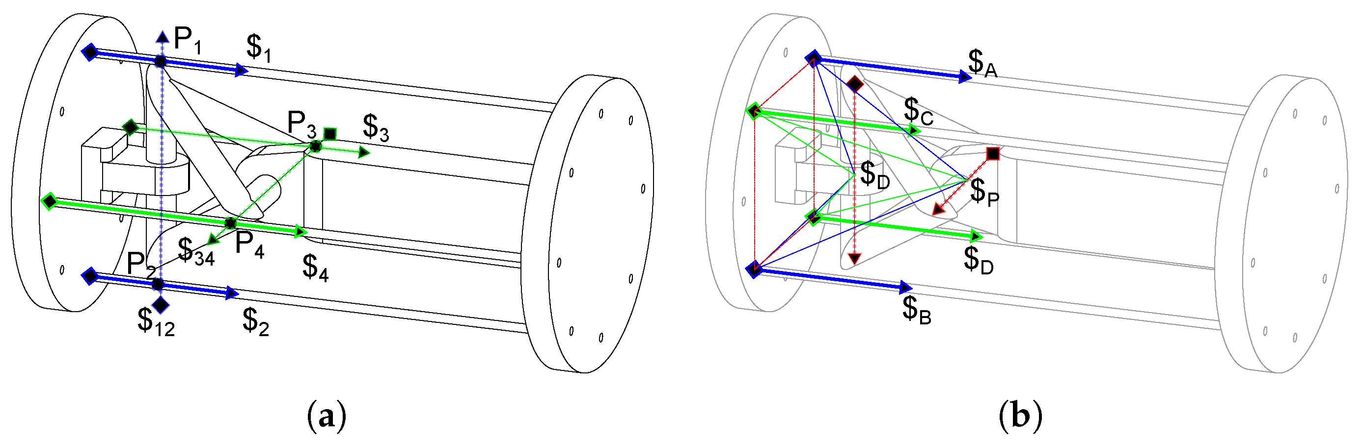
Cable-Driven Two-Rotational Serial Chain

In this subsection, we studied a model in three dimensions that is analogous to the ankle joint. The model uses the screws in an antagonistic configuration to achieve tension forces at the cables. In Figure 8b, the view is normal to the proximal axis, and Figure 8a shows the normal view of the distal axis.
We used this simplified model to compute the cable locations. Also, we can use the model for testing and calibrating the mechanism before use in humans. With the purpose of designing a reconfigurable physical model, we represent the rotational joints as axes located coincident in opposite edges on a tetrahedral structure, as shown in Figure 9. We chose two different configurations by rotating the anchor points by 0.7854 radians (half of 1.5708 radians) from their initial position on the base and the platform. The first coincides with the rotation axis as in Figure 9a, and the second configuration is similar to that observed in the ankle, and we show this configuration in Figure 9b.
The first representation allows us to visually identify the intersection points between the tendons’ lines of action.
L $ 1 L $ 12 = P 1 , L $ 2 L $ 12 = P 2
L $ 3 L $ 34 = P 3 , L $ 4 L $ 34 = P 4
Such a condition results in null reciprocal twists because they are coplanar [91]. Therefore, the reciprocal products are:
$ 1 $ 12 = 0 , $ 2 $ 12 = 0 ,
$ 3 $ 34 = 0 , $ 4 $ 34 = 0
This configuration must be avoided because it leads to a singularity. The relations for all the tendons on the rotary joints are as follows:
$ 12 $ 1 + $ 2 + $ 3 + $ 4 , $ 34 $ 1 + $ 2 + $ 3 + $ 4
In Figure 9a, we show the following:
$ 1 $ 34 = $ 1 $ 34 , $ 3 $ 12 = $ 4 $ 12
Following that, the sum of all reciprocal products is zero, which means that the platform is in a static position. However, it is unstable because little variation in the anchor position suddenly changes the product’s sign. In the second configuration, the twist pair $ A and $ C is antagonistic with regards to $ B and $ D about the proximal twist $ x . Also, $ C and $ B are antagonistic with respect to $ A and $ D about the twist $ t . We will use this in our design.
In summary, two conditions are important to avoid: singular configurations and cable collisions. We address the first condition by changing the angle position of the anchor points and the second condition by selecting the base and platform radiuses which are bigger than the foot standard size.

2.4. Robot Configuration

For simulation and validation, we generated trajectories and captured the axes pose using the formulas in the Supplementary Materials Sections S1.2 and S1.3. The method uses the formulas in the Supplementary Materials Section S1.4 for selecting the trajectories. The axis approximation formulas are in the Supplementary Materials Section S1.5. Finally, the range of motion and the common perpendicular line are in the Supplementary Materials Sections S1.6 and S1.7 complete the captured bi-axial model characterization. These data are important for the minimum and maximum cable lengths computation. We assume that the base plane is parallel to the transversal plane of the shank. With the reference systems aligned and P O and P M 0 centered on the base and the platform, the shank line is perpendicular to the foot plane, and the neutral position occurs when the four tendons have similar tension. Therefore, the actuators used in antagonistic operation will have seamless forces. When the platform of the foot is parallel to the transversal plane of the shank, the talocrural and subtalar axes projected to the plane in symmetric form are:
x r 1 x ω 1 x = y r 1 y ω 1 y , x r 2 x ω 2 x = y r 2 y ω 2 y
Solving for y yields:
y = ω 1 y ω 1 x x ω 1 y ω 1 x r 1 x + r 1 y ω 1 y
y = ω 2 y ω 2 x x ω 2 y ω 2 x r 2 x + r 2 y ω 2 y
Subtracting (35) from (34), we have:
x ω 1 y ω 1 x ω 2 y ω 2 x ω 1 y ω 1 x r 1 x ω 2 y ω 2 x r 2 x + r 1 y ω 1 y r 2 y ω 2 y = 0
Solving for x yields:
x p = ( ω 2 y r 2 x ω 2 x r 2 y ) ω 1 x + ( ω 1 x ω 2 x ω 1 y ω 2 x ) r 1 x ω 1 y ω 2 x ω 1 x ω 2 y
Replacing x in (33) and solving for y yields:
y p = ( ω 2 y r 2 x ω 2 x r 2 y ) ω 1 y + ( ω 1 x ω 2 y ω 1 y ω 2 y ) r 1 x ω 1 y ω 2 x ω 1 x ω 2 y
We created two planes parallel to the z-axis, coinciding with the intersecting point P i p = ( x p , y p ) :
Π 1 : ( P P i p ) · n ^ 1 z = 0 , Π 2 : ( P P i p ) · n ^ 2 z = 0
where the normal vectors are:
n ^ 1 z = ω ^ 1 × [ 0 , 0 , 1 ] , n ^ 2 z = ω ^ 2 × [ 0 , 0 , 1 ]
We computed the angle between the planes. This equation can be used to calculate the minimum and maximum angles, and the angles can be obtained as follows:
γ 12 = 1 2 arccos n ^ 1 z · n ^ 2 z | n 1 | | n 2 | ,
γ 21 = 1 2 π arccos n ^ 1 z · n ^ 2 z | n 1 | | n 2 |
We rotated the unitary vector normal to the planes γ 12 and γ 21 about an axis parallel to the z-axis and passed it through P i p . The resulting vectors are:
ω 12 = rot ( k ^ , γ 12 ) , ω 21 = rot ( k ^ , γ 21 )
where k ^ is the unitary vector in the direction of the positive z-axis.
The resulting lines in symmetric form are:
x x p ω 12 x = y y p ω 12 y , x x p ω 21 x = y y p ω 21 y
Following that, we obtained the pivot point P p p = x p p , y p p , z p p on the robot platform, and the pivot point P p b = x p b , y p b , z p b on the base, corresponding to x p , y p projected on the platform and the base. The platform and base attachment points are at the intersection between the circle centered on the pivot points P p p and P p b with the lines of Equations (44), and the circle equations are:
y 2 = r p 2 ( x x p p ) 2 + y p p , y 2 = r b 2 ( x x p b ) 2 + y p b
The platform radius is r p , and the base radius is r b . By solving for y in (44), substituting it in (45), and solving for x, we can obtain the following two values:
σ ω 12 x 2 + ω 12 y 2 y p p + r p 2 ω 12 x 2 y p p 2 ω 12 x 2 + ω 12 y 2
where:
σ = ω 12 x 2 + ω 12 y 2 x p p ω 12 x ω 12 y y p p
Substituting these values back into Equation (44) yields:
y a p 1 , a p 2 = y p p ω 12 y ω 12 x x p p x a p 1 , a p 2
Then, by substituting ω 12 by ω 21 , we can obtain the other two points. Finally, we obtained four points for the platform. Obtaining the base anchor points is similar to computing the platform anchor points, and by replacing P p p by P b p and r p by r b we computed four base corresponding points. The reconfigurable structure is easy to set up by changing the angle position given by:
θ p i = arctan ( y a p i , x a p i ) , θ b i = arctan ( y a b i , x a b i )
where θ p i and θ b i are the corresponding angles of each anchor point on the platform and the base related to the x direction around the intersection projected points P p p and P b p .

3. Workspace from the Product of Exponentials

By knowing the platform’s initial configuration, we can plot the anchor point group of movements from the product of exponential matrices by applying the Equation (17) to each platform anchor point a p i . The product of exponential matrix representing the group of movements g a p i for each anchor point a p i on the platform is:
g a p i = e ξ ^ 1 θ 1 e ξ ^ 2 θ 2 g a p i ( 0 ) = R a p i τ a p i 0 1 × 3 1
Moreover, the cable lengths can be calculated as follows:
l c i = τ a p i a b i
The range of the talocrural angle is θ 1 0.3491 , 0.3491 radians, and the subtalar angle range is θ 2 0.2618 , 0.2618 radians. The surfaces represent the group of movements for each anchor point on the platform.

Reconfiguration and Statics Simulation

The robot configuration depends on the ankle axis location. We compared the analogous two-axis system and the ankle biaxial model on MuJoCo 2.3.1. We used this software because it is open-source and free to use. Additionally, it is used for model-based control. We provided the XML source in [85]. The simulation process is easy, and we edited the tendon lengths in the text editor and reloaded the simulation in MuJoCo 2.3.1. We stopped the simulation, we changed the hinge joint angles, and then we ran the simulation with the computed tendon lengths. The simulation stops in a static position at previously computed angles.

4. Results

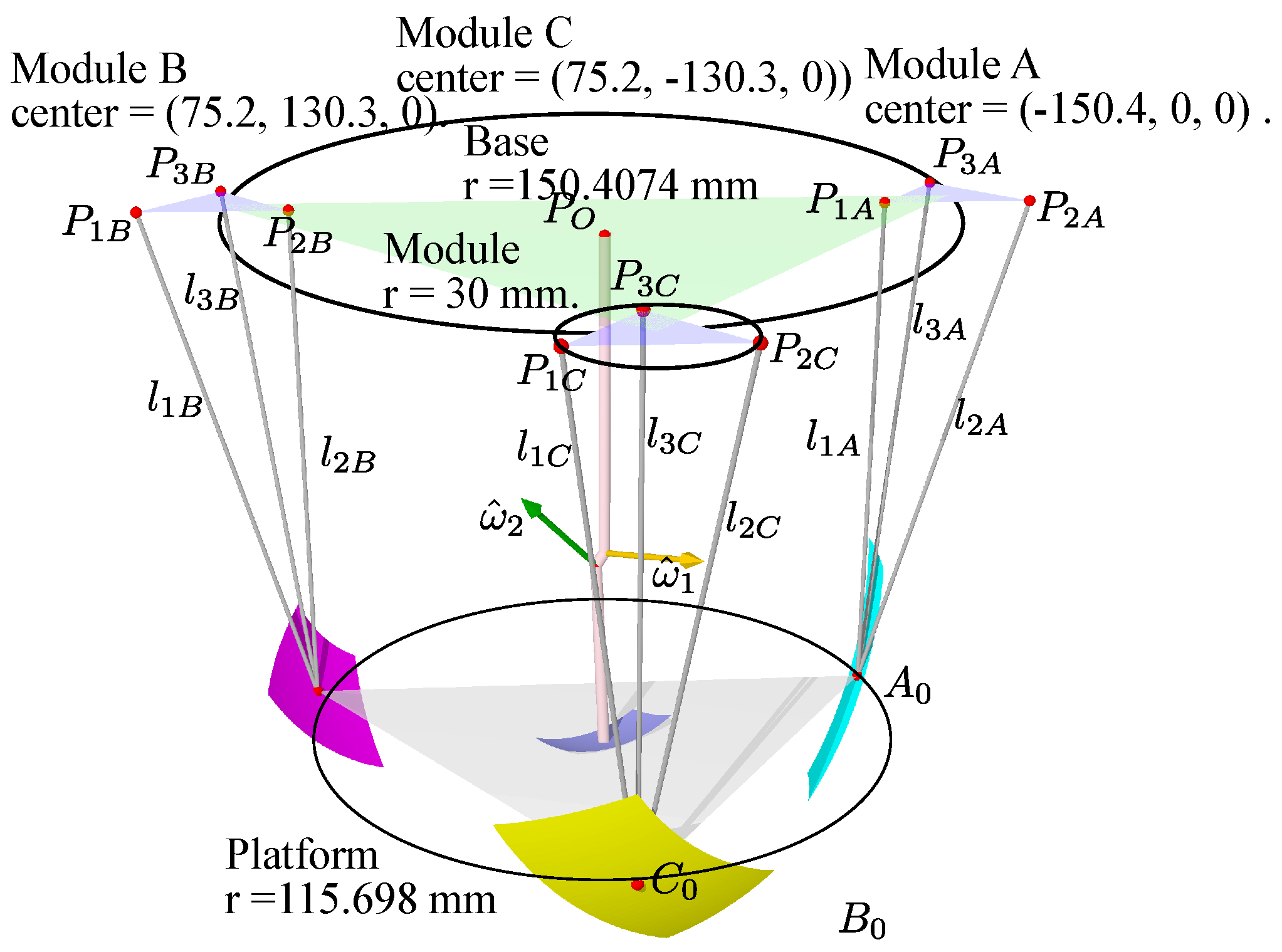
4.1. Base and Platform Dimensions

First, we show the resulting base radius for mean statistic height in Figure 10 with a relation r b = 1.3 r p . Every module has radius r m .
We computed the sensor lengths by subtracting points pertaining to the groups from the corresponding module vertexes. We started with the distance between the initial position from A 0 to the module P 1 A .
l 1 A = A 0 P 1 A ,
We did the same for modules B and C, then we got the lengths from each initial point for the corresponding sensors in Table 1. The lengths graphical representation is in Figure 10.
From the sensor lengths, we computed the initial position for A, B, and C from the Equations (S15)–(S17) on the Supplementary Materials. Following that, we compared the original with the computed sensor lengths in Table 2.
The table shows that the computed positions from the lengths corresponds to the given original values.

4.2. Intermediate Results

For the sake of simplifying the results section, we put all the intermediate results on the supplementary materials. We used data generated from the ankle model forward kinematics, using the formulas in the Supplementary Materials Section S1.2. The platform position uses the formulas in the Supplementary Materials Section S1.3. The most circular trajectories selection in practice uses the formulas in the Supplementary Materials Section S1.4. The axis approximation uses the formulas in the Supplementary Materials Section S1.5. The range of motion computations uses the formulas in Supplementary Materials Section S1.6. The common perpendicular formulas are in the Supplementary Materials Section S1.7.
The trajectories generation results are in the Supplementary Materials Section S2.1. The resulting common perpendiculars computations, a unique characteristic for each ankle, are in the Supplementary Materials Section S2.2. The range of motion results are in the Supplementary Materials Section S2.3. The trajectories from the group of movements are in the Supplementary Materials Section S2.4. The subtalar axis range of motion results are in the Supplementary Materials Section S2.4. The resulting base and platform sizes are in the Supplementary Materials Section S2.6. The resulting screws initial analysis is in the Supplementary Materials Section S2.7. The horizontal planes projection of the axes intersection point are in the Supplementary Materials Section S2.8. The results of the robot configuration are in the Supplementary Materials Section S2.9. The angle computation of the anchor points is in the Supplementary Materials Section S2.10. The robot workspace is in the Supplementary Materials Section S2.11. The initial position of cable lengths is in the Supplementary Materials Section S2.12. The cables lengths at extreme poses are in the Supplementary Materials Section S2.13. The MuJoCo simulation results are in the Supplementary Materials Section S2.14.

4.3. Resulting Robot Design

In this subsection, we used the data captured from the ankle model and integrated the draw-wire sensors into the robot. The device dimensions are based on human proportions with a mean height of H = 175 cm. The objective is to adjust the measurement device and the ankle-approximated model in a configurable structure. The design is intended for the laying position. We divided the design into two main subassemblies: the platform for the foot and the base for the shank.
The resulting platform design is based on the foot anatomy by observing the Figure 1a,b and Figure 2. The platform is adaptable to various foot sizes based on proportions [87]. The length is also adaptable, and we show the assembly in Figure 11. We added a length ruler, heel support, and three force sensing resistors (FSRs). Two FSRs are used for the forefoot, and one FSR is used for the hindfoot.
To align the center of the platform to P p p at the initial position we designed perpendicular sliders, as shown in Figure 12.
In Figure 13, we show the base assembly, with sensors for ankle axis estimation. We designed guides for centering the shank position P b p . The anchor points are manually adjusted in different positions, depending on the ankle model.
A main tube structure is attached to a baseplate. We used spacers and 8 mm steel bolts to fasten the two plates supporting the sensors. Finally, we placed Bowden guides for the cable endpoints.
The final design includes the platform, the sensors, the base, and a possible configuration for the actuators and electronics. We also show a resulting assembly with the approximated adjustable axis mechanical model in Figure 14.

5. Discussion

In this work, we show that, by using the human-centered design of an ankle rehabilitation robot, we can apply the device to a broader group of patients.
We focus on the ankle model specific to each patient to equilibrate tension and pressure forces in an initial position. For us, ankle kinematic model identification is imperative to configure the platform and base anchor points. We show that such a design can enhance the range of motion, adapting to several sizes on both feet. Using this human-centered approach, we can limit the pressure forces acting on the plantar surface of the foot to avoid unnatural positions. We estimated the platform and base sizes. We also ensured that the cables did not touch the foot. The cable lengths can reach the ankle joint range of motion. We reconfigured the robot around the initial equilibrium position. This position is like when the human body is standing. We used projected axes on the transversal planes perpendicular to gravity. Screw theory is a powerful tool, and the results show we can effectively use it in robot geometry, kinematics, and static analysis.
The screw theory based on two axes has unique characteristics such as common perpendicular, relative angles between the axes, and relative inclination regarding the sagittal, transversal, and coronal planes. We can compare left and right foot axes for stability analysis and gait disease diagnosis.
Using MuJoCo, we simulated the statics by editing an XML file with the computed tendon lengths and anchor points, then using sensors, the ankle joint angles measures are similar to those that are initially assumed. There are various biomechanic simulators such as AnyBody, OpenSim, and Myosuite. We can translate the ankle model obtained with our method to the XML files used in these simulators.

6. Conclusions

Ankle sprains are a common injury, and there is abundant research on ankle rehabilitation robots. We found that Screw Theory is applied in many works. By observing the anatomy, we realized that the tendons associated with the ankle movement are attached to the bones at the base of the plantar dome, transmitting pressure to the foot surface in contact with the platform. We designed the Turmell-Bot to be used by patients lying in bed or sitting. The robot configuration depends on the patient-specific ankle model. The model is an approximation that we can refine by using piece-wise function approximations and machine learning. We designed a lightweight, low-cost, low-energy, portable, configurable, and comfortable device. We enhanced the device with sensors to measure the foot pressure forces involved in ankle movements. We will use compliant actuators and ratchets to hold the desired position without energy consumption. We will search for antagonistic actuation and tension control. We also plan to integrate electromyography (EMG) and functional electrical stimulation (FES) through the shank attachment to register the activation signals when the device is making rehabilitation movements.

Limitations of the Present Work and Future Development and Improvements

Before building the device, we conducted exhaustive testing on various sizes using simulations. Our proposed method for scaling the device to fit a target population involves using statistics and proportions. For example, starting with a statistical mean height, we can adjust the dimensions accordingly and use 3D printing for the necessary attachments and supports. To further refine the models, we can create datasets on the target populations and implement machine learning techniques. Our approach to mapping the neural activity related to ankle rehabilitation involves using compliant actuators and EMG sensors on the shank. By utilizing this model, we can create anatomically functional prosthetics that work effectively near the ankle. The two-axis model expressed in screw theory terms can be unique to each patient. We can use the axes’ characteristics such as the attitude (relative to the sagittal, coronal, and transverse planes) and the common perpendicular segment between the two axes to study body stability and gait analysis.

Supplementary Materials

The following supporting information can be downloaded at: https://www.mdpi.com/article/10.3390/robotics12060154/s1.

Author Contributions

Conceptualization, Á.V. and J.V.-R.; methodology, J.V.-R. and Á.V.; software, J.V.-R.; validation, J.V.-R.; formal analysis, J.V.-R.; investigation, J.V.-R.; resources, Ó.A.-V. and Á.V.; data curation, J.V.-R. and Á.V.; writing—original draft preparation, J.V.-R.; writing—review and editing, J.V.-R., Ó.A.-V. and Á.V.; visualization, J.V.-R.; supervision, Á.V.; project administration, Ó.A.-V. and Á.V.; funding acquisition, Ó.A.-V. and Á.V. All authors have read and agreed to the published version of the manuscript.

Funding

This research was partially funded by Colciencias-Colfuturo PhD Scholarships Program Educational Credit Forgivable grant number 568, and by Agencia Estatal de Investigación (Ministerio de Ciencia e Innovación, Spanish Government) and Fondo Europeo de Desarrollo Regional through the Project ref. PID2021-125694OB-I00.

Institutional Review Board Statement

Not applicable.

Informed Consent Statement

Not applicable.

Data Availability Statement

Data available in https://github.com/juliohvr/Turmell-Bot (accessed on 10 November 2023). CAD in https://grabcad.com/library/turmell-bot-1 (accessed on 10 November 2023). Jupyter Notebook in https://nbviewer.org/github/juliohvr/Turmell-Bot/blob/main/TurmellBot.ipynb (accessed on 10 November 2023).

Acknowledgments

This works is supported in part by the Colombian Administrative Department of Science, Technology and Innovation, (Colciencias) under the 568 Doctorate program, the Automatics and Informatics Institute (ai2) at Universitat Politècnica de València, (UPV) and the Facultad de Ciencias Básicas e Ingeniería (FCBI) at Universidad de los Llanos (Unillanos).

Conflicts of Interest

The authors declare no conflict of interest.

Abbreviations

The following abbreviations are used in this manuscript:
ISBInternational Society of Biomechanics
CADComputer Aided Design
PoEProduct of Exponentials
TCTalocrural
STSubtalar
MTPMetatarsophalangeal
MMPMost Medial Point
MLPMost Lateral Point
PMPlatform Mean
EMGElectromyography
FESFunctional Electrostimulation

References

  1. Xiao, B.; Chen, C.; Yin, X. Recent advancements of robotics in construction. Autom. Constr. 2022, 144, 104591. [Google Scholar] [CrossRef]
  2. Delmerico, J.; Mintchev, S.; Giusti, A.; Gromov, B.; Melo, K.; Horvat, T.; Cadena, C.; Hutter, M.; Ijspeert, A.; Floreano, D.; et al. The current state and future outlook of rescue robotics. J. Field Robot. 2019, 36, 1171–1191. [Google Scholar] [CrossRef]
  3. Lytridis, C.; Bazinas, C.; Kalathas, I.; Siavalas, G.; Tsakmakis, C.; Spirantis, T.; Badeka, E.; Pachidis, T.; Kaburlasos, V.G. Cooperative Grape Harvesting Using Heterogeneous Autonomous Robots. Robotics 2023, 12, 147. [Google Scholar] [CrossRef]
  4. Tsiakas, K.; Papadimitriou, A.; Pechlivani, E.M.; Giakoumis, D.; Frangakis, N.; Gasteratos, A.; Tzovaras, D. An Autonomous Navigation Framework for Holonomic Mobile Robots in Confined Agricultural Environments. Robotics 2023, 12, 146. [Google Scholar] [CrossRef]
  5. Wang, Z.; Hirai, S.; Kawamura, S. Challenges and Opportunities in Robotic Food Handling: A Review. Front. Robot. AI 2022, 8, 789107. [Google Scholar] [CrossRef]
  6. Satav, A.G.; Kubade, S.; Amrutkar, C.; Arya, G.; Pawar, A. A state-of-the-art review on robotics in waste sorting: Scope and challenges. Int. J. Interact. Des. Manuf. (IJIDeM) 2023, 17, 2789–2806. [Google Scholar] [CrossRef]
  7. Bogue, R. The role of robots in entertainment. Ind. Robot 2022, 49, 667–671. [Google Scholar] [CrossRef]
  8. Ortega, L.D.; Loyaga, E.S.; Cruz, P.J.; Lema, H.P.; Abad, J.; Valencia, E.A. Low-Cost Computer-Vision-Based Embedded Systems for UAVs. Robotics 2023, 12, 145. [Google Scholar] [CrossRef]
  9. Chopra, H.; Baig, A.A.; Cavalu, S.; Singh, I.; Emran, T.B. Robotics in surgery: Current trends. Ann. Med. Surg. 2022, 81, 104375. [Google Scholar] [CrossRef]
  10. Hinrichs, P.; Seibert, K.; Gómez, P.A.; Pfingsthorn, M.; Hein, A. A Robotic System to Anchor a Patient in a Lateral Position and Reduce Nurses’ Physical Strain. Robotics 2023, 12, 144. [Google Scholar] [CrossRef]
  11. Soriano, G.P.; Yasuhara, Y.; Ito, H.; Matsumoto, K.; Osaka, K.; Kai, Y.; Locsin, R.; Schoenhofer, S.; Tanioka, T. Robots and Robotics in Nursing. Healthcare 2022, 10, 1571. [Google Scholar] [CrossRef]
  12. Vitiello, N.; Trigili, E.; Crea, S. Rehabilitation Robots; Springer: London, UK, 2020; pp. 1–6. [Google Scholar] [CrossRef]
  13. Gao, M.; Wang, Z.; Pang, Z.; Sun, J.; Li, J.; Li, S.; Zhang, H. Electrically Driven Lower Limb Exoskeleton Rehabilitation Robot Based on Anthropomorphic Design. Machines 2022, 10, 266. [Google Scholar] [CrossRef]
  14. Warutkar, V.; Dadgal, R.; Mangulkar, U.R. Use of Robotics in Gait Rehabilitation Following Stroke: A Review. Cureus 2022, 14, e31075. [Google Scholar] [CrossRef]
  15. Zhou, J.; Yang, S.; Xue, Q. Lower limb rehabilitation exoskeleton robot: A review. Adv. Mech. Eng. 2021, 13, 16878140211011862. [Google Scholar] [CrossRef]
  16. Shi, D.; Zhang, W.; Zhang, W.; Ding, X. A Review on Lower Limb Rehabilitation Exoskeleton Robots. Chin. J. Mech. Eng. 2019, 32, 74. [Google Scholar] [CrossRef]
  17. Mikolajczyk, T.; Ciobanu, I.; Badea, D.I.; Iliescu, A.; Pizzamiglio, S.; Schauer, T.; Seel, T.; Seiciu, P.L.; Turner, D.L.; Berteanu, M. Advanced technology for gait rehabilitation: An overview. Adv. Mech. Eng. 2018, 10, 1687814018783627. [Google Scholar] [CrossRef]
  18. Callegaro, A.M.; Unluhisarcikli, O.; Pietrusinski, M.; Mavroidis, C. Neuro-Robotics: From Brain machine Interfaces to Rehabilitation Robotics; Number 2 in Trends in Augmentation of Human Performance; Springer: Dordrecht, The Netherlands, 2014; pp. 265–283. [Google Scholar] [CrossRef]
  19. Ravella, K.C.; Ahmad, J.; Amirouche, F. Biomechanics of the Ankle Joint; Springer International Publishing: Cham, Switzerland, 2021; pp. 401–413. [Google Scholar] [CrossRef]
  20. Wu, G.; Siegler, S.; Allard, P.; Kirtley, C.; Leardini, A.; Rosenbaum, D.; Whittle, M.; D’Lima, D.D.; Cristofolini, L.; Witte, H.; et al. ISB recommendation on definitions of joint coordinate system of various joints for the reporting of human joint motion–part I: Ankle, hip, and spine. International Society of Biomechanics. J. Biomech. 2002, 35, 543–548. [Google Scholar] [CrossRef]
  21. Okubo, K.; Kervyn, G.; Zielinski, M.; Vinent, L.; Bigio, A.T.; Villar., C.T. Open Source Anatomy. Available online: https://github.com/LluisV/Z-Anatomy (accessed on 13 November 2023).
  22. Gregorio, R.D.; Parenti-Castelli, V.; O Connor, J.J.; Leardini, A. Mathematical models of passive motion at the human ankle joint by equivalent spatial parallel mechanisms. Med. Biol. Eng. Comput. 2007, 45, 305–313. [Google Scholar] [CrossRef]
  23. Lynch, K.M.; Park, F.C. (Eds.) Modern Robotics: Mechanics, Planning, and Control; Cambridge University Press: Cambridge, MA, USA, 2019. [Google Scholar]
  24. Gallardo-Alvarado, J. Kinematic Analysis of Parallel Manipulators by Algebraic Screw Theory; Springer International Publishing: Cham, Switzerland, 2016. [Google Scholar] [CrossRef]
  25. Zhao, J.; Feng, Z.; Chu, F.; Ma, N. Advanced Theory of Constraint and Motion Analysis for Robot Mechanisms; Academic Press: Oxford, UK, 2014. [Google Scholar]
  26. Ball, R.S. A Treatise on the Theory of Screws; Cambridge University Press: Cambridge, UK, 1998. [Google Scholar]
  27. Liao, Z.; Yao, L.; Lu, Z.; Zhang, J. Screw theory based mathematical modeling and kinematic analysis of a novel ankle rehabilitation robot with a constrained 3-PSP mechanism topology. Int. J. Intell. Robot. Appl. 2018, 2, 351–360. [Google Scholar] [CrossRef]
  28. Di, R. Parallel Manipulators with Lower Mobility. In Industrial Robotics: Theory, Modelling and Control; Pro Literatur Verlag: Mammendorf, Germany; ARS: Linz, Austria, 2006. [Google Scholar] [CrossRef]
  29. Gregorio, R.D. (Ed.) Kinematics and Robot Design I, KaRD2018; MDPI: Basel, Switzerland, 2021. [Google Scholar] [CrossRef]
  30. Gregorio, R.D. (Ed.) Kinematics and Robot Design IV, KaRD2021; MDPI: Basel, Switzerland, 2022. [Google Scholar] [CrossRef]
  31. Gregorio, R.D. Kinematics and Robot Design II (KaRD2019) and III (KaRD2020); MDPI AG: Basel, Switzerland, 2022. [Google Scholar]
  32. Gregorio, R.D. (Ed.) Kinematics and Robot Design V, KaRD2022; MDPI: Basel, Switzerland, 2023. [Google Scholar] [CrossRef]
  33. Tarnita, D.; Dumitru, N.; Pisla, D.; Carbone, G.; Geonea, I. (Eds.) New Trends in Medical and Service Robotics: MESROB 2023; Mechanisms and Machine Science; Springer Nature: Cham, Switzerland, 2023; Volume 133. [Google Scholar] [CrossRef]
  34. Rauter, G.; Carbone, G.; Cattin, P.C.; Zam, A.; Pisla, D.; Riener, R. (Eds.) New Trends in Medical and Service Robotics: MESROB 2021; Mechanisms and Machine Science; Springer International Publishing: Cham, Switzerland, 2021; Volume 106. [Google Scholar] [CrossRef]
  35. Rauter, G.; Cattin, P.C.; Zam, A.; Riener, R.; Carbone, G.; Pisla, D. (Eds.) New Trends in Medical and Service Robotics: MESROB 2020; Mechanisms and Machine Science; Springer International Publishing: Cham, Switzerland, 2020; Volume 93. [Google Scholar] [CrossRef]
  36. Carbone, G.; Ceccarelli, M.; Pisla, D. (Eds.) New Trends in Medical and Service Robotics: Advances in Theory and Practice; Mechanisms and Machine Science; Springer International Publishing: Cham, Switzerland, 2019; Volume 65. [Google Scholar] [CrossRef]
  37. Bleuler, H.; Bouri, M.; Mondada, F.; Pisla, D.; Rodic, A.; Helmer, P. (Eds.) New Trends in Medical and Service Robots: Assistive, Surgical and Educational Robotics; Mechanisms and Machine Science; Springer International Publishing: Cham, Switzerland, 2016; Volume 38. [Google Scholar] [CrossRef]
  38. Rodić, A.; Pisla, D.; Bleuler, H. (Eds.) New Trends in Medical and Service Robots: Challenges and Solutions; Mechanisms and Machine Science; Springer International Publishing: Cham, Switzerland, 2006; Volume 20. [Google Scholar] [CrossRef]
  39. Caro, S.; Pott, A.; Bruckmann, T. (Eds.) Cable-Driven Parallel Robots: Proceedings of the 6th International Conference on Cable-Driven Parallel Robots; Mechanisms and Machine Science; Springer Nature Switzerland: Cham, Switzerland, 2023; Volume 132. [Google Scholar] [CrossRef]
  40. Gouttefarde, M.; Bruckmann, T.; Pott, A. (Eds.) Cable-Driven Parallel Robots: Proceedings of the 5th International Conference on Cable-Driven Parallel Robots; Mechanisms and Machine Science; Springer International Publishing: Cham, Switzerland, 2021; Volume 104. [Google Scholar] [CrossRef]
  41. Pott, A.; Bruckmann, T. (Eds.) Cable-Driven Parallel Robots: Proceedings of the 4th International Conference on Cable-Driven Parallel Robots; Mechanisms and Machine Science; Springer International Publishing: Cham, Switzerland, 2019; Volume 74. [Google Scholar] [CrossRef]
  42. Pott, A. Cable-Driven Parallel Robots: Theory and Application; Springer Tracts in Advanced Robotics; Springer International Publishing: Cham, Switzerland, 2019; Volume 120. [Google Scholar] [CrossRef]
  43. Gosselin, C.; Cardou, P.; Bruckmann, T.; Pott, A. (Eds.) Cable-Driven Parallel Robots; Mechanisms and Machine Science; Springer International Publishing: Cham, Switzerland, 2018; Volume 53. [Google Scholar] [CrossRef]
  44. Pott, A.; Bruckmann, T. (Eds.) Cable-Driven Parallel Robots: Proceedings of the Second International Conference on Cable-Driven Parallel Robots; Mechanisms and Machine Science; Springer International Publishing: Cham, Switzerland, 2017; Volume 32. [Google Scholar] [CrossRef]
  45. Bruckmann, T.; Pott, A. (Eds.) Cable-Driven Parallel Robots; Mechanisms and Machine Science; Springer: Cham, Switzerland, 2014; Volume 12. [Google Scholar] [CrossRef]
  46. Boschetti, G.; Trevisani, A. Cable Robot Performance Evaluation by Wrench Exertion Capability. Robotics 2018, 7, 15. [Google Scholar] [CrossRef]
  47. Di Gregorio, R. A Review of the Literature on the Lower-Mobility Parallel Manipulators of 3-UPU or 3-URU Type. Robotics 2020, 9, 5. [Google Scholar] [CrossRef]
  48. Di Gregorio, R. A Novel 3-URU Architecture with Actuators on the Base: Kinematics and Singularity Analysis. Robotics 2020, 9, 60. [Google Scholar] [CrossRef]
  49. Valderrama-Rodríguez, J.I.; Rico, J.M.; Cervantes-Sánchez, J.J.; García-García, R. A Screw Theory Approach to Computing the Instantaneous Rotation Centers of Indeterminate Planar Linkages. Robotics 2022, 11, 6. [Google Scholar] [CrossRef]
  50. Flores-Salazar, E.D.; Arias-Montiel, M.; Lugo-González, E.; Gallardo-Alvarado, J.; Tapia-Herrera, R. Alternative Methods for Direct Kinematic Analysis of a Parallel Robot for Ankle Rehabilitation. In New Trends in Medical and Service Robotics; Rauter, G., Cattin, P.C., Zam, A., Riener, R., Carbone, G., Pisla, D., Eds.; Mechanisms and Machine Science; Springer International Publishing: Cham, Switzerland, 2021; pp. 53–61. [Google Scholar] [CrossRef]
  51. Metcalf, A.G.; Gallagher, J.F.; Jackson, A.E.; Levesley, M.C. Multi-Domain Dynamic Modelling of a Low-Cost Upper Limb Rehabilitation Robot. Robotics 2021, 10, 134. [Google Scholar] [CrossRef]
  52. Zakaryan, N.; Harutyunyan, M.; Sargsyan, Y. Bio-Inspired Conceptual Mechanical Design and Control of a New Human Upper Limb Exoskeleton. Robotics 2021, 10, 123. [Google Scholar] [CrossRef]
  53. Khan, M.M.R.; Swapnil, A.A.Z.; Ahmed, T.; Rahman, M.M.; Islam, M.R.; Brahmi, B.; Fareh, R.; Rahman, M.H. Development of an End-Effector Type Therapeutic Robot with Sliding Mode Control for Upper-Limb Rehabilitation. Robotics 2022, 11, 98. [Google Scholar] [CrossRef]
  54. Zhou, Y.; Zhang, B.; Shang, W.; Cong, S. Configuration Optimization of an Auto-reconfigurable Cable-Driven Upper-Limb Rehabilitation Robot. In Cable-Driven Parallel Robots; Gouttefarde, M., Bruckmann, T., Pott, A., Eds.; Mechanisms and Machine Science; Springer International Publishing: Cham, Switzerland, 2021; pp. 145–157. [Google Scholar] [CrossRef]
  55. Ceresoli, F.; Aggogeri, F.; Amici, C.; Borboni, A.; Faglia, R.; Pellegrini, N.; Tiboni, M.; Antonini, M.; Fausti, D.; Mor, M.; et al. Differential System for Limb Rehabilitation. In New Trends in Medical and Service Robotics; Carbone, G., Ceccarelli, M., Pisla, D., Eds.; Mechanisms and Machine Science; Springer International Publishing: Cham, Switzerland, 2018; pp. 3–10. [Google Scholar] [CrossRef]
  56. Bouri, M.; Abdi, E.; Bleuler, H.; Reynard, F.; Deriaz, O. Lower Limbs Robotic Rehabilitation Case Study with Clinical Trials; Mechanisms and Machine Science; Springer International Publishing: Cham, Switzerland, 2014; pp. 31–44. [Google Scholar] [CrossRef]
  57. Badi, A.; Saad, M.; Gauthier, G.; Archambault, P. Inverse Kinematics for a Novel Rehabilitation Robot for Lower Limbs. In Cable-Driven Parallel Robots; Gosselin, C., Cardou, P., Bruckmann, T., Pott, A., Eds.; Mechanisms and Machine Science; Springer International Publishing: Cham, Switzerland, 2018; pp. 376–389. [Google Scholar] [CrossRef]
  58. Geonea, I.; Tarnita, D.; Carbone, G.; Ceccarelli, M. Design and Simulation of a Leg Exoskeleton Linkage for Human Motion Assistance. In New Trends in Medical and Service Robotics; Carbone, G., Ceccarelli, M., Pisla, D., Eds.; Mechanisms and Machine Science; Springer International Publishing: Cham, Switzerland, 2019; pp. 93–100. [Google Scholar] [CrossRef]
  59. Copilusi, C.; Ceccarelli, M.; Dumitru, S.; Margine, A.; Geonea, I. A Leg Exoskeleton Mechanism for Human Walking Assistance. In New Trends in Medical and Service Robotics; Tarnita, D., Dumitru, N., Pisla, D., Carbone, G., Geonea, I., Eds.; Mechanisms and Machine Science; Springer Nature: Cham, Switzerland, 2023; pp. 160–167. [Google Scholar] [CrossRef]
  60. Pramod, A.S.; Palani, P.; Mohan, S.; Thondiyath, A. Development of a Passive Ankle-Foot Exoskeleton for Variable Force Resistance Training. In New Trends in Medical and Service Robotics; Tarnita, D., Dumitru, N., Pisla, D., Carbone, G., Geonea, I., Eds.; Mechanisms and Machine Science; Springer Nature: Cham, Switzerland, 2023; pp. 144–151. [Google Scholar] [CrossRef]
  61. Nursultan, Z.; Ceccarelli, M.; Balbayev, G. Design and Performance Analysis of Ankle Joint Exoskeleton. In New Trends in Medical and Service Robotics; Tarnita, D., Dumitru, N., Pisla, D., Carbone, G., Geonea, I., Eds.; Mechanisms and Machine Science; Springer Nature: Cham, Switzerland, 2023; pp. 152–159. [Google Scholar] [CrossRef]
  62. Nakka, S.; Vashista, V. Manipulability Analysis of Cable-Driven Serial Chain Manipulators. In Cable-Driven Parallel Robots; Caro, S., Pott, A., Bruckmann, T., Eds.; Mechanisms and Machine Science; Springer Nature: Cham, Switzerland, 2023; pp. 16–29. [Google Scholar] [CrossRef]
  63. Tucan, P.; Ulinici, I.; Pop, N.; Puskas, F.; Carbone, G.; Gherman, B.; Luchian, I.; Pisla, D. Ankle Rehabilitation of Stroke Survivors Using Kuka LBR Iiwa. In New Trends in Medical and Service Robotics; Rauter, G., Cattin, P.C., Zam, A., Riener, R., Carbone, G., Pisla, D., Eds.; Mechanisms and Machine Science; Springer International Publishing: Cham, Switzerland, 2020; pp. 29–36. [Google Scholar] [CrossRef]
  64. Girone, M.J.; Burdea, G.C.; Bouzit, M. The “Rutgers Ankle” Orthopedic Rehabilitation Interface. In Proceedings of the ASME 1999 International Mechanical Engineering Congress and Exposition, Dynamic Systems and Control, Nashville, TN, USA, 14–19 November 1999; Dynamic Systems and Control. American Society of Mechanical Engineers Digital Collection: New York, NY, USA, 2021; pp. 305–312. [Google Scholar] [CrossRef]
  65. Wang, C.; Fang, Y.; Guo, S.; Chen, Y. Design and Kinematical Performance Analysis of a 3-RUS/RRR Redundantly Actuated Parallel Mechanism for Ankle Rehabilitation. J. Mech. Robot. 2013, 5, 041003. [Google Scholar] [CrossRef]
  66. Saglia, J.A.; Dai, J.S. Geometry and Kinematic Analysis of a Redundantly Actuated Parallel Mechanism for Rehabilitation. In Proceedings of the ASME 2007 International Design Engineering Technical Conferences and Computers and Information in Engineering Conference, Volume 8: 31st Mechanisms and Robotics Conference, Parts A and B, Las Vegas, NV, USA, 4–7 September 2007; American Society of Mechanical Engineers Digital Collection: New York, NY, USA, 2009; pp. 1081–1090. [Google Scholar] [CrossRef]
  67. Chen, G.; Mao, Z.; Zhou, H.; Yang, P. Design and control strategy of 3-prismatic-revolute-spherical ankle rehabilitation robot. Aust. J. Mech. Eng. 2023, 21, 1079–1092. [Google Scholar] [CrossRef]
  68. Escarabajal, R.J.; Abu-Dakka, F.J.; Pulloquinga, J.L.; Mata, V.; Vallés, M.; Valera, Á. Development of lower-limb rehabilitation exercises using 3-PRS Parallel Robot and Dynamic Movement Primitives. Multidiscip. J. Educ. Soc. Technol. Sci. 2020, 7, 30–44. [Google Scholar] [CrossRef]
  69. Dong, M.; Kong, Y.; Li, J.; Fan, W. Kinematic Calibration of a Parallel 2-UPS/RRR Ankle Rehabilitation Robot. J. Healthc. Eng. 2020, 2020, 3053629. [Google Scholar] [CrossRef]
  70. Li, J.; Zuo, S.; Zhang, L.; Dong, M.; Zhang, Z.; Tao, C.; Ji, R. Mechanical Design and Performance Analysis of a Novel Parallel Robot for Ankle Rehabilitation. J. Mech. Robot. 2020, 12, 051007. [Google Scholar] [CrossRef]
  71. Wang, L.; Chang, Y.; Zhu, H. Internal Model Control and Experimental Study of Ankle Rehabilitation Robot. Robotica 2020, 38, 940–956. [Google Scholar] [CrossRef]
  72. Doroftei, I.; Cazacu, C.M. Developments in the Design of an Ankle Rehabilitation Platform. In New Trends in Medical and Service Robotics; Tarnita, D., Dumitru, N., Pisla, D., Carbone, G., Geonea, I., Eds.; Mechanisms and Machine Science; Springer Nature: Cham, Switzerland, 2023; pp. 179–187. [Google Scholar] [CrossRef]
  73. Wang, C.; Wang, L.; Wang, T.; Li, H.; Du, W.; Meng, F.; Zhang, W. Research on an Ankle Joint Auxiliary Rehabilitation Robot with a Rigid-Flexible Hybrid Drive Based on a 2-SPS Mechanism. Appl. Bionics Biomech. 2019, 2019, 7071064. [Google Scholar] [CrossRef] [PubMed]
  74. Zhong, J.; He, D.; Zhao, C.; Zhu, Y.; Zhang, Q. An rehabilitation robot driven by pneumatic artificial muscles. J. Mech. Med. Biol. 2020, 20, 2040008. [Google Scholar] [CrossRef]
  75. Zhang, M.; Cao, J.; Xie, S.Q.; Zhu, G.; Zeng, X.; Huang, X.; Xu, Q. A Preliminary Study on Robot-Assisted Ankle Rehabilitation for the Treatment of Drop Foot. J. Intell. Robot. Syst. 2018, 91, 207–215. [Google Scholar] [CrossRef]
  76. Zhang, M.; Xie, S.Q.; Li, X.; Zhu, G.; Meng, W.; Huang, X.; Veale, A.J. Adaptive Patient-Cooperative Control of a Compliant Ankle Rehabilitation Robot (CARR) with Enhanced Training Safety. IEEE Trans. Ind. Electron. 2018, 65, 1398–1407. [Google Scholar] [CrossRef]
  77. Sales Gonçalves, R.; Carvalho, J.; Rodrigues, L.A.; Marques Barbosa, A. Cable-Driven Parallel Manipulator for Lower Limb Rehabilitation. Appl. Mech. Mater. 2013, 459, 535–542. [Google Scholar] [CrossRef]
  78. Wang, Y.L.; Wang, K.Y.; Chai, Y.J.; Mo, Z.J.; Wang, K.C. Research on mechanical optimization methods of cable-driven lower limb rehabilitation robot. Robotica 2022, 40, 154–169. [Google Scholar] [CrossRef]
  79. Vaida, C.; Birlescu, I.; Pisla, A.; Carbone, G.; Plitea, N.; Ulinici, I.; Gherman, B.; Puskas, F.; Tucan, P.; Pisla, D. RAISE—An Innovative Parallel Robotic System for Lower Limb Rehabilitation. In New Trends in Medical and Service Robotics; Carbone, G., Ceccarelli, M., Pisla, D., Eds.; Mechanisms and Machine Science; Springer International Publishing: Cham, Switzerland, 2019; pp. 293–302. [Google Scholar] [CrossRef]
  80. Yu, R.; Fang, Y.; Guo, S. Design and Kinematic Analysis of a Novel Cable-Driven Parallel Robot for Ankle Rehabilitation. In Advances on Theory and Practice of Robots and Manipulators; Ceccarelli, M., Glazunov, V.A., Eds.; Mechanisms and Machine Science; Springer International Publishing: Cham, Switzerland, 2014; pp. 293–301. [Google Scholar] [CrossRef]
  81. Venkata Sai Prathyush, I.; Ceccarelli, M.; Russo, M. Control Design for CABLEankle, a Cable Driven Manipulator for Ankle Motion Assistance. Actuators 2022, 11, 63. [Google Scholar] [CrossRef]
  82. The Sage Developers. SageMath, the Sage Mathematics Software System (Version 10.0); 2023; Available online: https://www.sagemath.org (accessed on 20 July 2023).
  83. Vargas-Riaño, J.H. Turmell-Bot-Nbviewer. Available online: https://nbviewer.org/github/juliohvr/Turmell-Bot/blob/main/TurmellBot.ipynb (accessed on 10 November 2023).
  84. Vargas-Riaño, J.H. Turmell-Bot | 3D CAD Model Library | GrabCAD. Available online: https://grabcad.com/library/turmell-bot-1 (accessed on 10 November 2023).
  85. Vargas-Riaño, J.H. Juliohvr/Turmell-Bot: Turmell-Bot. Available online: https://github.com/juliohvr/Turmell-Bot (accessed on 10 November 2023). [CrossRef]
  86. Isman, R.E.; Inman, V.T. Anthropometric Studies of the Human Foot and Ankle; Biomechanics Laboratory, University of California: Riverside, CA, USA, 1969. [Google Scholar]
  87. Drillis, R.; Contini, R. Body Segment Parameters; New York University, School of Engineering and Science: New York, NY, USA, 1966. [Google Scholar]
  88. Fryar, C.D.; Carroll, M.D.; Gu, Q.; Afful, J.; Ogden, C.L. Anthropometric Reference Data for Children and Adults: United States, 2015–2018. 2021; pp. 1–44. Available online: https://stacks.cdc.gov/view/cdc/100478 (accessed on 10 November 2023).
  89. Agudelo-Varela, Ó.; Vargas-Riaño, J.; Valera, Á. Turmell-Meter: A Device for Estimating the Subtalar and Talocrural Axes of the Human Ankle Joint by Applying the Product of Exponentials Formula. Bioengineering 2022, 9, 199. [Google Scholar] [CrossRef]
  90. Todorov, E.; Erez, T.; Tassa, Y. MuJoCo: A physics engine for model-based control. In Proceedings of the 2012 IEEE/RSJ International Conference on Intelligent Robots and Systems, Vilamoura-Algarve, Portugal, 7–12 October 2012; pp. 5026–5033. [Google Scholar] [CrossRef]
  91. Zhao, J.; Li, B.; Yang, X.; Yu, H. Geometrical method to determine the reciprocal screws and applications to parallel manipulators. Robotica 2009, 27, 929–940. [Google Scholar] [CrossRef]
Figure 1. Lateral top and medial bottom views of the ankle-foot anatomy. (a) Lateral top view with components tangential to each axis. (b) Medial bottom view with components tangential to each axis [21].
Robotics 12 00154 g001
Figure 2. Right foot’s bottom plantar plane projection with contact points and joint axis.
Robotics 12 00154 g002
Figure 3. Ankle model and ankle rehabilitation robot sketch. (a) Schematic representation of the approximated tendon directions in a neutral position. (b) Schematic representation of reconfiguration.
Robotics 12 00154 g003
Figure 4. Size design from proportions and statistics. (a) Proportions. (b) Three dimensional simplified design.
Robotics 12 00154 g004
Figure 5. Product of exponentials representation of the ankle joint [89].
Robotics 12 00154 g005
Figure 6. Base and platform sizes initial approximation. (a) Leg coronal section. (b) Collision, range of motion, and antagonistic actuation.
Robotics 12 00154 g006
Figure 7. Maximum displacement.
Robotics 12 00154 g007
Figure 8. Normal views of the proximal and distal axis regarding the base. (a) Normal view of the proximal axis. (b) Normal view of the distal axis.
Robotics 12 00154 g008
Figure 9. First approximation with orthogonal axis coplanar to the tendons. (a) Antagonistic cables screws representation. (b) Screw representation for the anchor points rotated 0.7854 radians.
Robotics 12 00154 g009
Figure 10. Resulting dimensions of the platform, base and sensor modules.
Robotics 12 00154 g010
Figure 11. Foot’s size adjust.
Robotics 12 00154 g011
Figure 12. Centering the platform.
Robotics 12 00154 g012
Figure 13. Centering the base.
Robotics 12 00154 g013
Figure 14. CAD design.
Robotics 12 00154 g014
Table 1. Distances from the initial points to the corresponding sensors.
Sensor ModuleDistance to P 1 Distance to P 2 Distance to P 3
A l 1 A = 176.2 l 2 A = 184.9 l 3 A = 184.9
B l 1 B = 176.2 l 2 B = 311.1 l 3 B = 269.9
C l 1 C = 293.9 l 2 C = 269.9 l 3 C = 311.1
Table 2. Platform points computation.
PointOriginal from the ModelEstimation from Lengths
A 0 (−115.7, 0, −176.18)(−115.7, −0, −176.18)
B 0 (57.849, −100.2, −176.18)(57.849, −100.2, −176.18)
C 0 (57.849, 100.2, −176.18)(57.849, 100.2, −176.18)
Disclaimer/Publisher’s Note: The statements, opinions and data contained in all publications are solely those of the individual author(s) and contributor(s) and not of MDPI and/or the editor(s). MDPI and/or the editor(s) disclaim responsibility for any injury to people or property resulting from any ideas, methods, instructions or products referred to in the content.

