1. Introduction
The rapid growth of the global elderly population poses significant challenges. Studies showed that in 2022, people aged over 65 years old accounted for nearly 10% of the world’s population, and is expected to reach 16% in 2050 [
1]. In Japan, which leads globally in the aging trend, the elderly represented 26% of its population in 2014 [
2], with forecasts estimating an increase to 38.8% by 2050 [
3]. The aging process brings various mobility impairments due to musculoskeletal issues, neurological issues, chronic conditions, medication impacts, and psychological factors. These impairments can diminish the life quality and daily independence of the elderly, increasing dependency on long-term care, which adds economic strain and contributes to labor shortages. To address these concerns and enhance the quality of life for the aging population, robotic wheelchairs have emerged as a promising assistive innovation, offering potential solutions. While advancements in robotic wheelchair technology have been notable in recent years [
4,
5], ensuring the safety and autonomous operation of these devices remains a critical challenge. Enhancing wheelchair intelligence to minimize the reliance on manual control is key to improving the quality of life for the elderly who are experiencing mobility impairments.
The early research focused on stability control systems designed for robotic wheelchairs [
6]. The primary objective of a robotic wheelchair is to determine an optimal or suitable path between a starting point and a destination point, considering various constraints and objectives. The navigation task is similar to the common path-planning problem in traffic management, which requires determining the optimal path that satisfies a series of requirements [
7]. Over the years, many path-planning methods have been developed for various academic and practical applications [
8,
9]. Rapidly Exploring Random Trees (RRT) is an algorithm frequently used in dynamic and complex situations. Its primary purpose is to efficiently explore the search space and to generate feasible paths [
10]. The utility of RRT was further demonstrated in experiments involving cooperative robotics, where it proved successful in enabling a group of robots to push a box coordinated without collisions [
11]. Similarly, the genetic algorithm (GA) has established itself as an effective optimization tool for path planning. Studies have shown its effectiveness in environments with stationary and mobile obstacles [
12]. Although the above-mentioned strategy has a wide search range, rapid search speed, and high computational efficiency, the high calculation cost and slow convergence speed are two intractable shortcomings.
Additionally, the graph search algorithm is another widely used methodology for path planning, which has proven to be effective in navigating complex environments. One commonly used graph search algorithm is Dijkstra’s algorithm, which guarantees finding the shortest path in terms of distance or cost [
13]. Another popular algorithm is the A* algorithm, which extends Dijkstra’s algorithm by introducing a heuristic function that estimates the remaining cost from each node to the target. This heuristic helps guide the search towards the target and can significantly improve the search efficiency [
14]. The A* algorithm was employed for mobile robots in indoor disaster areas, and the experimental results demonstrated the effectiveness of the approach in enabling the robot to successfully navigate and explore the indoor disaster area [
15]. In [
16], the simulation results in a Mars-like scenario validated the applicability of the A* algorithm in minimizing the traveling time and energy consumption, while maintaining the safety of exploration robots. In addition to its applications in robotic path planning, Santos J et al. [
17] introduced an A*-based planning and scheduling approach designed for the management of multiple automated guided vehicles within an industrial environment. It provided an efficient means for planning routes and schedules, optimizing operations in complex industrial environments. Studies indicate that the A* algorithm can be used to balance optimality and efficiency, with its heuristic-guided search and efficient data structures making it particularly fit for dealing with path-planning problems in extensive environments.
However, the limitation of these path-planning strategies is their inability to consider the dynamic characteristics of the control plant. Model predictive control (MPC) is a highly effective technique employed in motion control across various domains. By formulating an optimization problem over a defined prediction horizon, MPC enables the determination of an optimal sequence of control actions that minimize the given cost function, while considering system dynamics and constraints. The existing literature has shown that MPC is especially suitable for dynamic environments and complex robot dynamics scenarios. Its real-time adaptability and optimality make it a powerful tool for effectively generating optimal paths and successfully navigating complex environments [
18,
19]. Previous research by Rosmann C et al. [
20] has demonstrated the effectiveness of an innovative approach to online motion planning using nonlinear MPC with non-Euclidean rotation groups in various scenarios. This method addresses the challenges posed by environments with non-Euclidean geometry and complex robot dynamics. Farina M conducted a comprehensive investigation on the use of distributed MPC for motion coordination in unicycle autonomous robots. Their research demonstrated the effectiveness of this control strategy in enhancing the performance and efficiency of robots in various tasks and scenarios [
21]. In [
22], the successful application of dynamic nonlinear MPC for both path planning and tracking control in unmanned transportation systems was highlighted. Meanwhile, Ref. [
23] introduced an MPC-based framework that emphasized the safety of robots in unpredictable environments, demonstrating their effectiveness in navigating dynamic obstacles and uncertainties. Bjelonic M et al. [
24] also introduced an optimization-based framework uniting offline motion libraries with online MPC to enable robots with legs and wheels to perform complex locomotion skills. It combined long-time horizon planning and short-time horizon solutions, allowing smooth transitions between diverse motions while ensuring effective feedback control and resilience to disturbances. In conclusion, these results highlight the potential of the MPC scheme for practical applications in motion control for robotic systems. The demonstrated effectiveness of the MPC approach in generating optimized and safe trajectories reveals its viability and applicability in various real-world scenarios.
The development of robot control requires complex mathematical structures to describe their transformation in space. Among many mathematical tools, the dual quaternion as a particularly effective tool has attracted much attention in the field of robotics. It has the ability to represent rotation and translation simultaneously. In [
25], the use of dual quaternion to help robots move precisely in position and direction was explored. The study not only introduced the mathematical principle behind this method but also validated its control ability through experiments with real robots and confirmed that it was a promising method for better robot control. Then, a reliable library for robot modeling and control using dual quaternion was further developed, which was popularly used recently [
26]. This library capitalizes on the strengths of dual quaternions in representing 3D transformations, offering a robust toolbox for modern robotic applications. A dual-quaternion-based robot forward kinematics algorithm in the Robot Operating System (ROS) was implemented in [
27]. The proposed implementation provided an accurate and efficient solution for solving forward kinematics problems in robotic systems, thereby enhancing the capabilities of ROS for robot control and handling. In conclusion, dual quaternions can be used in robotic control to consider both the position and the direction of the action, thus improving the safety of robot operation and realizing directional movement. Therefore, in this work, we make use of the unique characteristics of dual quaternion, combined with an MPC control scheme, to enhance the motion of robotic wheelchairs.
In this work, a robotic wheelchair system based on ROS is built first. Then, a hierarchical motion control strategy for the robotic wheelchair that ensures safe and directional movement in an unknown environment is presented. The proposed strategy includes a global path planner, which determines an optimal path in the overall environment, and an MPC local controller, which takes into account the specific dynamics and constraints of the robotic wheelchair. Particularly, a novel approach that combines a dual-quaternion-based spherical linear interpolation (SLERP) technique with the MPC scheme is used in the local controller. The dual quaternion can effectively capture the complex spatial transformations required for robot control, which enables the robotic wheelchair to achieve reliable and directional navigation. This integration allows for smooth and continuous transitions between different poses of the robotic wheelchair during movement. The dual-quaternion-based SLEPP MPC local controller is employed to address disturbances in the local map, effectively solving the motion control issue of local obstacle avoidance and path optimization. Finally, the experimental results in the ROS simulation environment and real-world scenarios demonstrate the effectiveness of the proposed control strategy in achieving self-driving and safe navigation in unknown environments for robotic wheelchairs. Furthermore, the experimental results revealed the prospective capability of our proposed control strategy in addressing dynamic obstacle avoidance challenges that arise in the future.
The remainder of the paper proceeds as follows. In
Section 2, the considered robotic wheelchair is first introduced and formulated by the so-called unicycle model, and then the hierarchical motion control problem is proposed. In
Section 3, the comprehensive framework is proposed. The path planning strategy using the A* algorithm to generate a global path is first described. In the following parts, this section intends to achieve the MPC local path planner, introducing a dual-quaternion-based SLERP technique. In
Section 4, the validation results and discussions are presented. Finally, the conclusions are summarized in
Section 5.
3. Self-Driving Motion Control
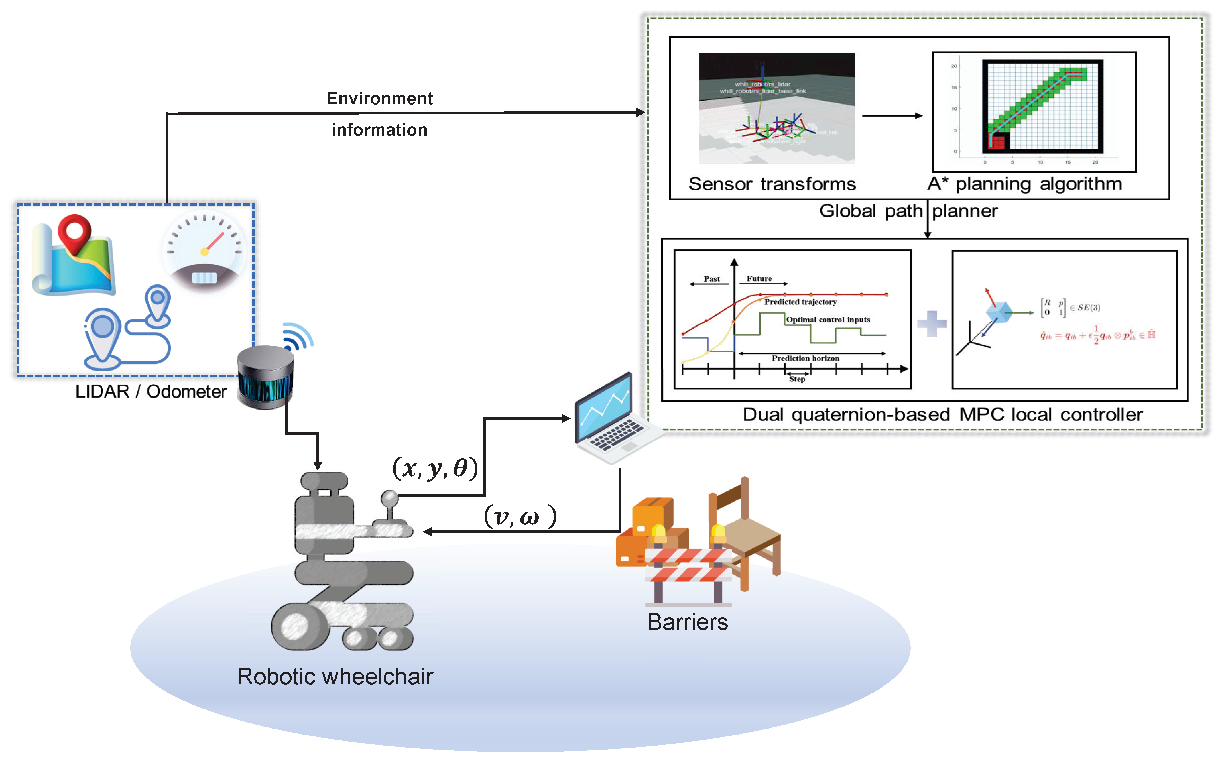
In this section, we present a hierarchical control strategy for ensuring safe and directional movement in unknown scenarios, as shown in
Figure 4. The construction of our hierarchical motion control system is depicted within the green-dotted box on the right of the figure. Utilizing the point cloud data from 3d-LiDAR and odometer data from the wheelchair, a PC generates real-time action decisions, enabling the robotic wheelchair’s autonomous navigation. The strategy consists of two layers: the upper layer, which involves a global path planner utilizing the A* algorithm to generate efficient paths and avoid obstacles from the start position to the target, and the lower layer, which employs MPC local controller considering wheelchair dynamic constraints to achieve safe and directional motion around obstacles. The developed dual-quaternion-based SLERP MPC local controller serves as a vital component in our proposed system, focusing on optimizing local paths and poses while providing effective motion control. In particular, the use of a dual-quaternion-based SLERP technique enables the robotic wheelchair to handle translation and rotation movement simultaneously in diverse scenarios. In terms of implementation, the output of the global path planner serves as the input for the local path planner, enabling coordinated and obstacle-aware navigation for the wheelchair. The implementation of the proposed MPC local controller is able to handle disruptions within local maps, effectively addressing issues of local obstacle avoidance challenges in motion control. Its rapid response to dynamic changes and disturbances in the local map reveals that our robotic wheelchair can effectively navigate in complex environments, making real-time adjustments to path optimization and obstacle avoidance. This capability enhances the safety and efficiency of self-driving robotic wheelchairs, facilitating their smooth and reliable performance.
3.1. The Global Path Planner Using A* Algorithm
A* algorithm is utilized in this work to generate an optimal trajectory that avoids obstacles and boundaries. The A* algorithm is chosen for the global path planning of our wheelchair due to its optimal pathfinding capability, heuristic efficiency, and adaptability to varied environments. Its deterministic nature ensures the reliable navigation of the wheelchair in the actual environment. The A* algorithm’s ability to re-calculate routes in dynamic settings is critical for obstacle avoidance, prioritizing user safety. Furthermore, its scalability and resource efficiency make it practical for the computational limits of onboard systems. It is a heuristic search algorithm that evaluates the estimated value of each search position using an evaluation function. The algorithm selects the position with the best-estimated value and continues the search until it reaches the target point.
where
represents the evaluation function of node
n from the initial node to the target node, and
denotes the actual cost, indicating the total cost from the initial node to the current node. Moreover,
represents the estimated cost of the optimal path from the current node to the target node, serving as the heuristic function in the A* algorithm. The two terms,
and
, play a crucial role in the A* algorithm as they determine the evaluation and selection of nodes during the search process. Since the robot can move in all directions, the Euclidean distance calculation algorithm is suitable for measuring distances between nodes. This can be described as follows:
where
x and
y, respectively, represent the lateral and longitudinal coordinates of the current node position, and
and
, respectively, represent the corresponding coordinates of the target node position. It is obvious that the closer the robot is to the target node, the smaller the value of the function
h will be. Consequently, this results in a relatively small value of
f. Therefore, by employing the A* algorithm with its heuristic search strategy, this section achieves efficient and effective trajectory generating, ensuring safe and obstacle-free navigation for the robotic wheelchair in unknown environments. The details for the use of the A* algorithm in the ROS platform can be found in [
29].
3.2. MPC-Based Local Controller
In real-life scenarios, the upper global path planner is unable to consider the dynamics of the wheelchair, resulting in an unsafe or shaking motion that leads to low driving comfort. To address this issue, an MPC-based local controller is introduced in this section. The local path planner utilizes a dual-quaternion-based SLERP approach, enabling the smooth and continuous interpolation of poses. By incorporating the MPC local controller, real-time optimal control actions are computed using a predictive optimization scheme.
The motion control problem of robotics is formulated into a discretized optimization problem under the MPC framework. The goal is to minimize predicted tracking errors and control efforts while satisfying constraints on the system dynamics. The formulation of the MPC optimization problem is as follows:
where
and
represent the deviation from the desired path generated by the A* algorithm,
denotes the control effort, and
and
represent the constraint of movement direction.
With the following constraints:
where
,
N is the control horizon;
is the k-steps ahead state computed based on the current state
; function
p is defined as state function of the robotic wheelchair dynamic in discretized form in Equation (
1);
,
,
, and
are the lower and upper bounds on the states; and
,
,
, and
are the lower and upper bounds on the control inputs, respectively.
,
, and
are the weights. The position
is the reference path generated by the A* algorithm, while
is provided by the dual-quaternion-based SLERP algorithm that will be introduced in
Section 3.3.
In this problem, the cost function incorporates three main components. Firstly, it penalizes the difference between the pose of the robot and the desired pose at the target point. This ensures that the robot follows the intended trajectory closely. Secondly, the cost function includes a term that penalizes the control effort, aiming to achieve smooth and energy-efficient motion. Thirdly, the via points serve as nodes in the graph optimization problem, forming a close graph with the reference trajectory that constrains the movement direction of the wheelchair. For more details, refer to [
30]. The control commands generated by the MPC local planner are then applied to the motion system of the robotic wheelchair, resulting in safe motions and directional movements.
The efficacy of the proposed MPC controller in handling local disruptions and navigating around obstacles is rooted in its predictive and optimization-centric nature. MPC is a complex control strategy capable of handling constrained multivariable control problems. The MPC-based controller predicts the future state of the wheelchair based on its dynamic model, current states, and a series of upcoming control inputs. The MPC controller considers the current state, the reference path, the via points, and any potential obstacles within its prediction horizon. It formulates an optimization problem where the control inputs are adjusted to minimize a cost function. When it encounters disruptions or obstacles, the MPC controller updates its predictions at each control cycle, recalculating the optimal control actions required to navigate around the obstacles while still trying to adhere to the constraints. The local map is continuously updated with sensor data, and the MPC controller incorporates this information into its predictions. If an obstacle is detected within the local map, the MPC planner evaluates the need to change the wheelchair’s trajectory by solving the optimization problem with the updated constraints. This ensures that the wheelchair avoids obstacles while maintaining its path toward the destination.
3.3. Dual-Quaternion-Based SLERP Algorithm
Our proposed approach integrates the dual quaternions theory, the SLERP technique, and MPC into the enhanced local controller by generating a control sequence constrained by the via points and reference trajectory. The via points are extracted from the poses generated with the dual-quaternion-based SLERP method. The reference trajectory is generated by the global planner. In this work, a significant advantage of such combinations is their ability to handle translation and orientation simultaneously, ensuring directional movement for the wheelchair.
In our proposed MPC local controller, SLERP, which was first introduced by Shoemaker [
31], is effectively employed to ensure the smooth and continuous interpolation of poses. It generates intermediate orientations between two given orientations, ensuring a seamless transition between them.
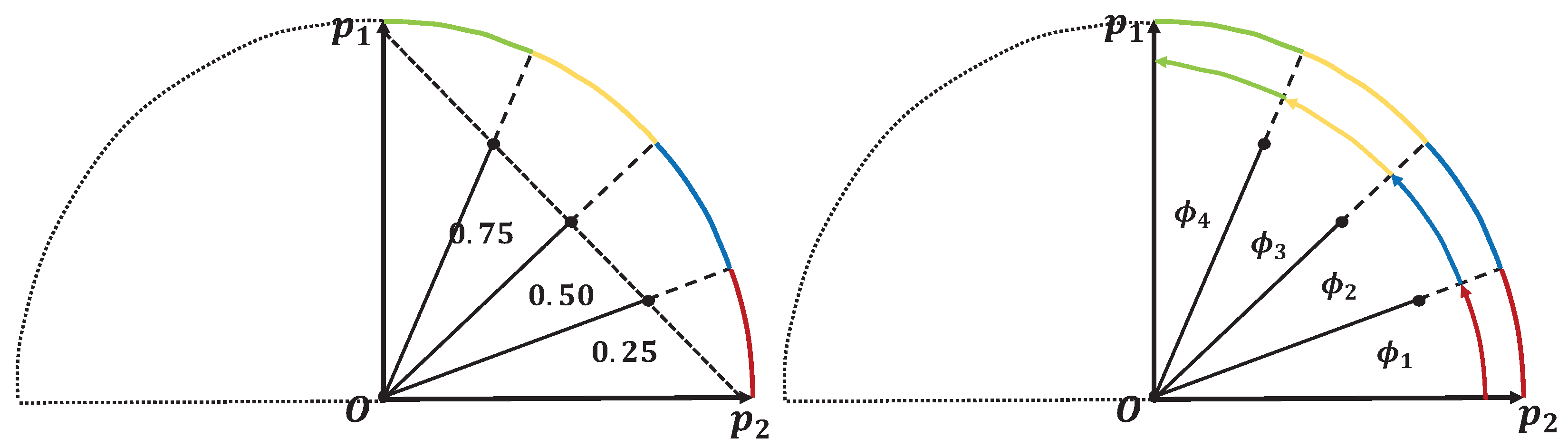
Figure 5 illustrates the schematic diagram comparing the SLERP interpolation method with the traditional linear interpolation method. It can be found that SLERP considers the shortest path on the unit sphere to smoothly rotate from one orientation to another.
The dual quaternion is known for its ability to handle both translation and orientation in a unified manner. A dual quaternion is an extension of a quaternion using the dual number that consists of a real part and a dual part. A dual quaternion can be represented as:
where
and
are quaternions,
is the dual unit, and
. For rigid body transformations,
represents the rotation, and
contains the translation information. In particular,
is a unit quaternion and
, where
is a quaternion representing the translation vector.
In our designed robotic wheelchair controller, the combination of dual quaternions and SLERP is employed in the local path planner to achieve smooth and continuous transition poses between the current pose
and the last pose
in the prediction horizon. This enables the wheelchair to navigate the planned path while maintaining consistent and continuous poses, ensuring safe and directional motion. The interpolation parameter
is used to calculate the interpolated quaternion
, which represents the robot’s orientation at a given point along the trajectory. The interpolated quaternion
by the SLERP method can be mathematically described as follows:
where
represents the norm of a dual quaternion, defined as:
In the use of SLERP, we are interested in interpolating between two unit dual quaternions (
). Consequently, the dual-quaternion-based SLERP formula can be simplified as:
Therefore, to calculate the transition poses between the current pose
and the last pose
in the prediction horizon, we can use the dual-quaternion-based SLERP method described above. For the specific calculation process, please refer to the steps shown in
Appendix A. The via point
extracted from the transition pose calculated by (
9) served as a node within the graph optimization problem. With the transition poses corresponding to the interpolations at the parameter value
, the via points are utilized by the MPC scheme to calculate control commands. By solving the MPC problem tracking the reference trajectory while considering the via points at each time step, and applying the resulting control inputs, the wheelchair realizes the directional movement tracking the reference trajectory generated by the global planner and the consistent poses generated by dual-quaternion-based SLERP, while adhering to its dynamic constraints.
4. Simulation and Experimental Results
In our study, we have developed a robotic wheelchair model and the proposed control system within the ROS platform for validation. This model serves as the basis for both the simulation and the experiment. Through a combination of simulation and real-world experiments, we can clearly validate the effectiveness and our strategy in navigating a robotic wheelchair through complex scenarios. The results reveal that our proposed control system is robust and reliable, confirming its ability to provide safe and efficient navigation solutions for practical applications.
4.1. Experimental Setup
To validate the proposed optimal control strategy, we utilize the ROS platform, an open-source robotics middleware, to create a simulation scenario for the robotic wheelchair. The ROS platform provides a comprehensive set of software libraries and tools specifically for the development of robotic systems, thus simplifying the integration and implementation of robotic applications. It acts as a bridge between the underlying operating system and the robot actuator, enabling communication and coordination between various software components. ROS can serve as an intermediate platform to connect the operating system to the robot’s controller, reducing the complexity of developing new control algorithms.
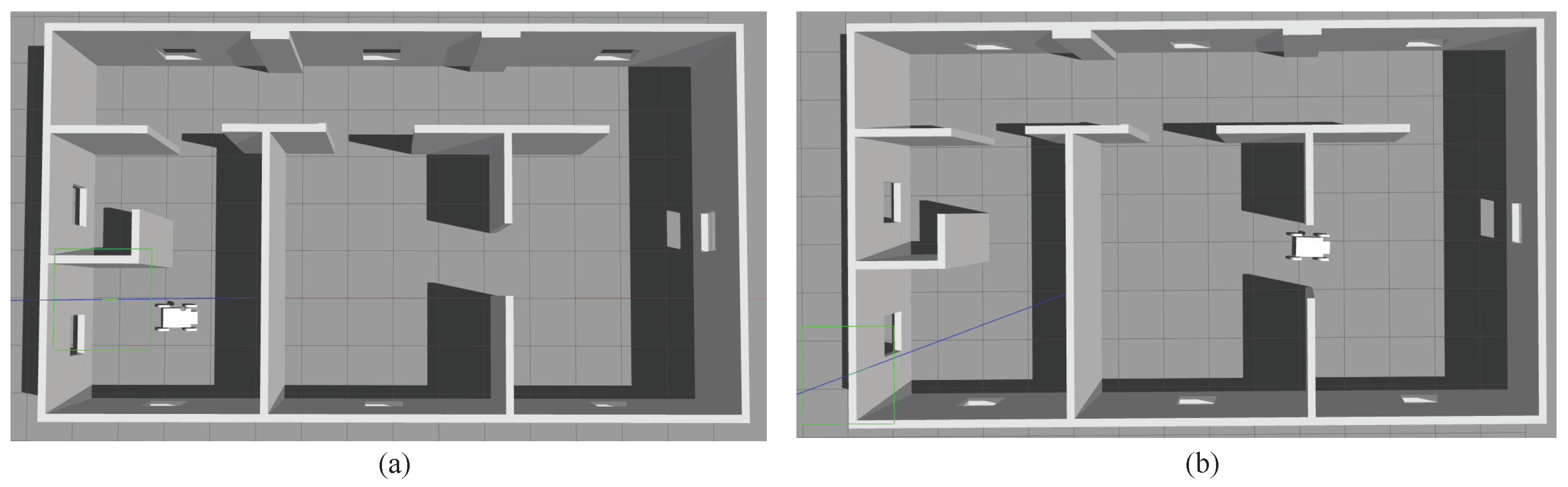
In our study, we build a robotic wheelchair model equipped with 3D-LiDAR within the ROS environment, as illustrated in
Figure 6. The simulation model of the robotic wheelchair is constructed with a focus on dimensional accuracy, mirroring the actual size of the physical wheelchair. The simplified model contains the essential components—wheels, chassis, and footrest—ensuring that the virtual representation corresponds closely to its real-world counterpart in terms of size and form factor. To replicate the sensor of the wheelchair, a simulated 3D-LiDAR sensor is positioned in the same location as on the actual robotic wheelchair. By maintaining consistency with the physical dimensions and sensory setup of the actual wheelchair, the simulation model enables us to conduct experiments that denote real-world performance. This level of detail in the simulation model is critical for validating the proposed motion control framework and ensures that the findings of our simulation tests are transferable to practical applications. The red (x-axis), green (y-axis), and blue (z-axis) straight lines in this figure represent the original coordinate system of the simulation environment. In
Figure 6b, the white block represents the initial pose of the wheelchair, the green rectangular represents the present footprint of the wheelchair, the yellow arrows are the position vector via points, the three colored coordinates are the via pose generated by the dual-quaternion-based SLERP, the red sphere near the coordinates represents the end of prediction horizon of the proposed MPC controller, the blue curve represents the local path, and the purple arrow represents the target pose. The control algorithms can be realized in this platform, which is shown in the right diagram in
Figure 6. This choice enables us to make use of the capabilities of ROS for simulation, control, and analysis, ensuring a robust and realistic evaluation of the proposed control strategy.
4.2. Simulation Results
In this section, the effectiveness of our designed strategy is validated in simulations. The performance of the control strategy was evaluated based on the results of trajectory tracking accuracy, obstacle avoidance ability, and the overall stability of the wheelchair. The selected case study is designed to simulate real-world scenarios that are common in daily life. The limitation constraints for the wheelchair in the optimization are determined as follows: the five terms are set to [m/s], [ m/s], [rad/s], and [rad/s]. The simulation was run on a laptop. The CPU is Ryzen 7-4800H, the GPU is RTX 2060, and the MEMORY is 24 GB. The experiment was run with another laptop. In our study, the solver of the optimization problem is the Interior Point Optimizer (Ipopt), which is a popular open-source optimization library. It is a powerful optimization solver used in ROS for solving nonlinear optimization problems.
To validate the performance of the proposed MPC local controller, which utilizes dual-quaternion-based SLERP interpolation, we conducted a comparative simulation case study using the ROS. In this work, we use the timed elastic band (TEB) local planner, a local path planner for mobile robots, as a benchmark. The TEB local planner is a path-planning algorithm for mobile robots to generate dynamically feasible trajectories. It optimizes the robot’s path by adjusting a series of timed waypoints to navigate around obstacles while respecting the robot’s locomotion capabilities. The TEB planner is integrated with ROS and is one of the common methods for mobile robot trajectory planning. Furthermore, we use the Gazebo environment shown in
Figure 7 for simulation and utilize RViz in
Figure 8 and
Figure 9 for visualization. Gazebo is a powerful robot simulation software that integrates with the Robot Operating System (ROS). It offers the ability to accurately and efficiently simulate populations of robots in complex indoor and outdoor environments. RViz is an open-source 3D interactive visualization tool in ROS. It is highly configurable and enables developers to visualize sensor inputs like 3D-LiDAR and camera feeds, robot status, and planned trajectories in a real-time interface. Its functionality is extendable through plugins, accommodating a broad spectrum of visualization needs in robotic development. Rviz facilitates the display of 3D robot models and the environments they navigate, offering interactive tools for direct manipulation and monitoring. These features make Rviz a powerful tool for debugging and improving robotic systems, allowing for an intuitive assessment and diagnosis of a robot’s performance and issues.
With the aim of enhancing accuracy and reliability in our simulation results, we designed repeated comparison experiments in the same scenario. These results allow us to conduct thorough comparisons and analyses of the outcomes, shown in
Table 1. It should be noted that the proposed method was implemented in the same simulation environment. We implemented eight simulation tests in the same scenario, shown in
Table 2. For the TEB local planner, 4 out of 8 times the wheelchair could reach the goal pose. For the SLERP MPC local controller, 5 of 8 times the wheelchair could reach the goal pose. Although the success rates are almost the same, the failure states are not the same. In
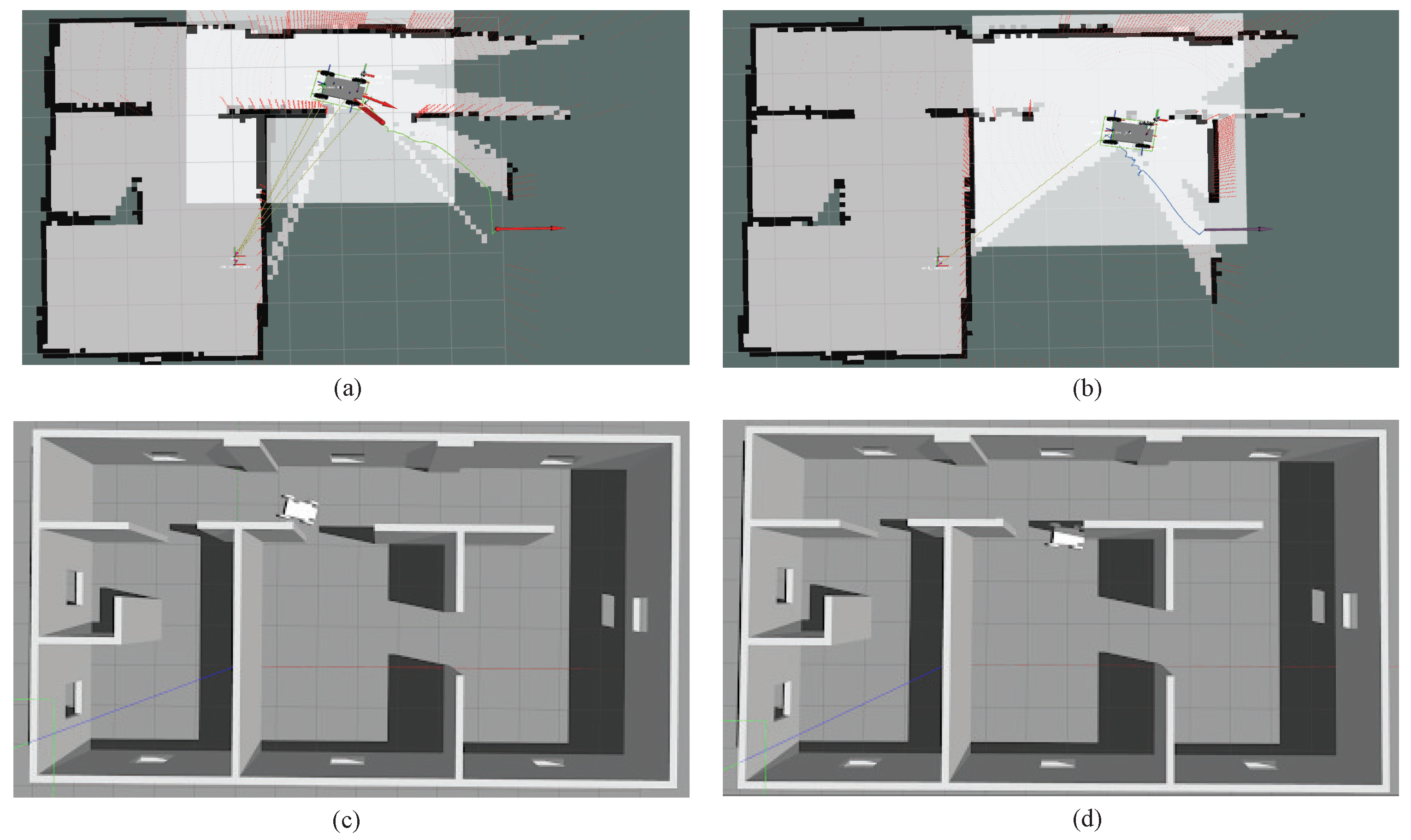
Figure 8a, the red lines on the wall are the simulated lidar beams, the green line represents the global path, the red arrow on the wheelchair represents the moving direction, the red arrow on the right represents the target pose, and the yellow lines represent positions vectors. In
Figure 8b, the purple arrow on the right represents the target pose, and the blue line represents the local path generated by TEB local planner. For the TEB local planner, the motion was stopped by the wheelchair hitting the wall, shown in
Figure 8b,d. However, with our proposed dual-quaternion-based SLERP MPC local controller, the motion was stopped because the solver failed to solve the MPC optimal problem. During the failure scenario, the wheelchair will stop at a safe area without contacting the walls, as shown in
Figure 8a,c. With a new proper target pose published, the wheelchair will continue its motion. With such a character, our designed controller is more suitable for real applications. In the real application, safety is important for the wheelchair and the movement of the wheelchair can be restarted again by publishing a new target pose.
In the following, we provide a detailed analysis and discussion of the comparative simulation results under specific test cases.
The simulation scenario we built is shown in
Figure 7, where the initial pose of the robotic wheelchair is shown in subgraph (a), and the target pose is shown in subgraph (b). The initial position is set as
, and the initial orientation is
. The target position is
, and the target orientation is
.
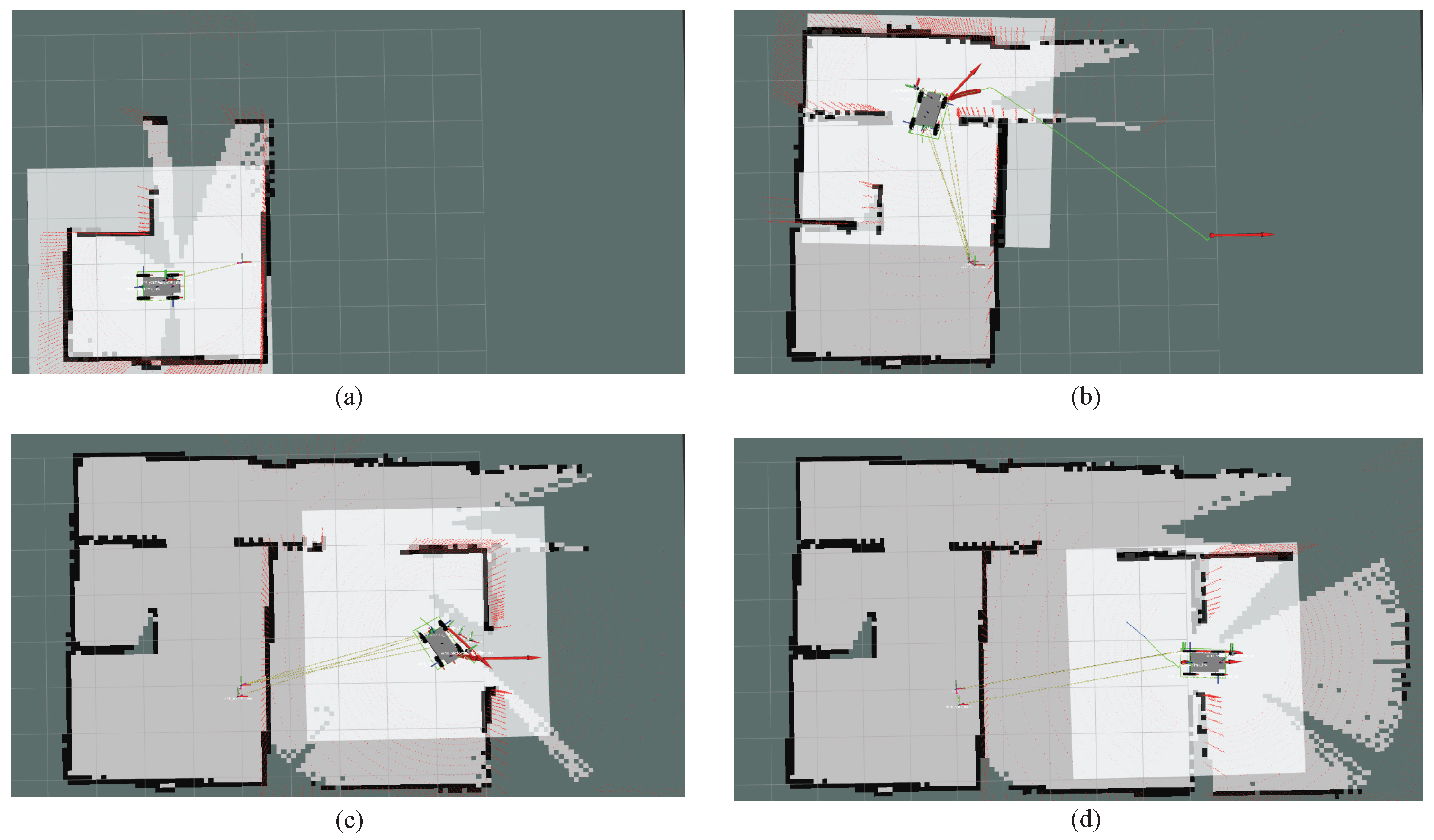
The corresponding search process is demonstrated in
Figure 9, where (a) represents the initial pose of the wheelchair in motion and the navigation process with our proposed MPC local controller, and (b), (c), (d) shows that the wheelchair safely avoids obstacles (walls) with the proposed MPC local controller while plotting the map with SLAM algorithm. It should be noted that the colored lines in
Figure 9 have the same meaning as in
Figure 8a. Using the control system we designed, the robotic wheelchair has the ability to avoid obstacles, turn around corners, and pass through corridors, while, most importantly, maintaining its motion safety and realizing directional movement.
The comparative simulation results of Case 1 comparing Test 1 in
Table 1 and
Table 2 are illustrated in
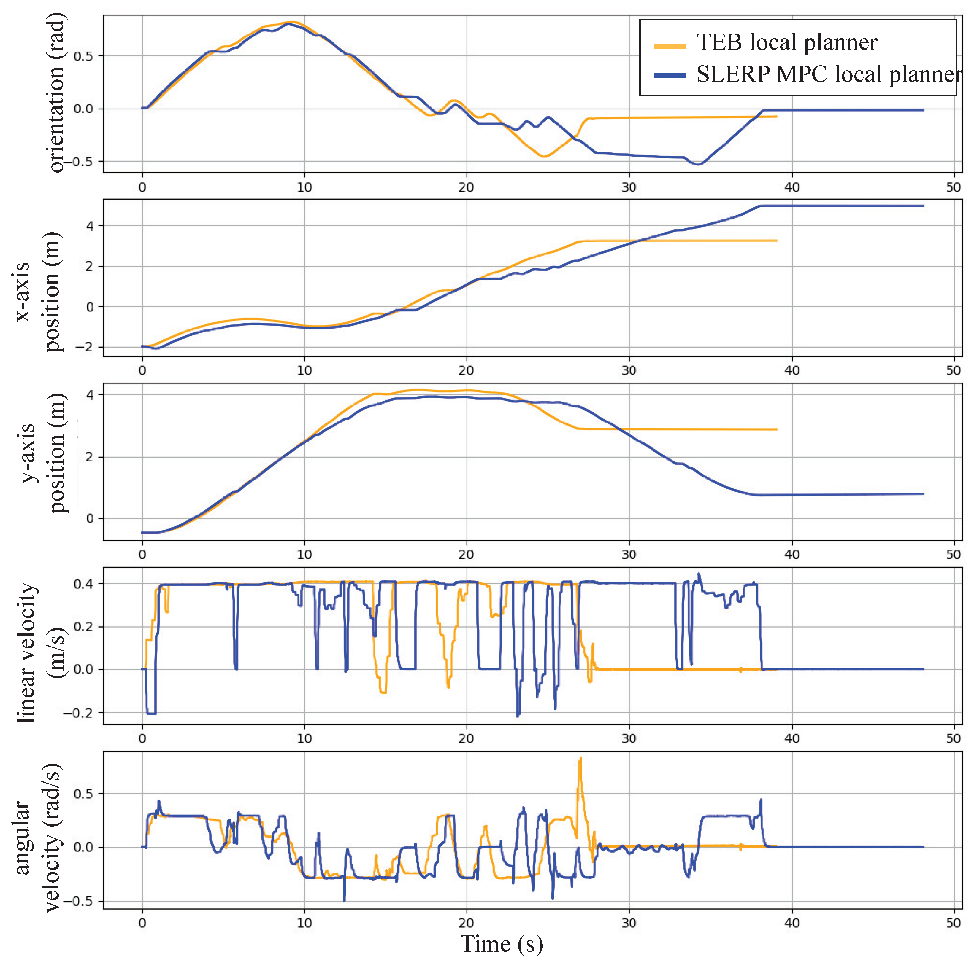
Figure 10. From top to bottom, these figures represent the wheelchair’s orientation, its position along the x-axis, its position along the y-axis during motion, and the linear and angular velocity profiles of the robotic wheelchair. The yellow curve represents the result without the MPC strategy, while the blue curve represents the comparison when using the SLERP MPC local controller that we designed. It can be observed that at the 27-second mark when the robotic wheelchair encounters an obstacle, the robotic wheelchair is unable to realize the obstacle avoidance and pauses without our proposed motion controller, while the wheelchair can avoid the obstacle and continue the motion using our designed hierarchical motion controller. Furthermore, it is worth noting that the utilization of dual-quaternion-based SLERP within the MPC controller accounts for both rotational and translational movement simultaneously; the wheelchair realizes the directional movement without unnecessary orientation and noticeable sharp fluctuations. In summary, the proposed strategy enables the wheelchair to generate safe and directional movement in a complex scenario.
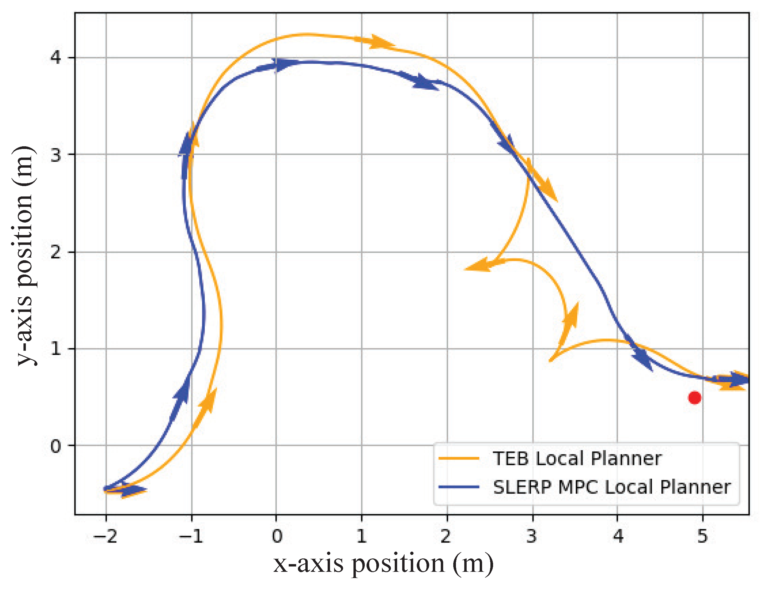
Figure 11 shows the trajectory simulation comparison of the two controllers under case 2 comparing Test 4 in
Table 1 and
Table 2, where the arrow on the curve represents the movement direction of the wheelchair. It can be clearly seen that the yellow trajectory curve, representing the wheelchair using the TEB controller, has trajectory offset and unnecessary rotation when encountering obstacles and approaching the target. In comparison, with the same initial and target pose, the trajectory using the controller we proposed is more stable and realizes directional movement without unnecessary rotation. Then,
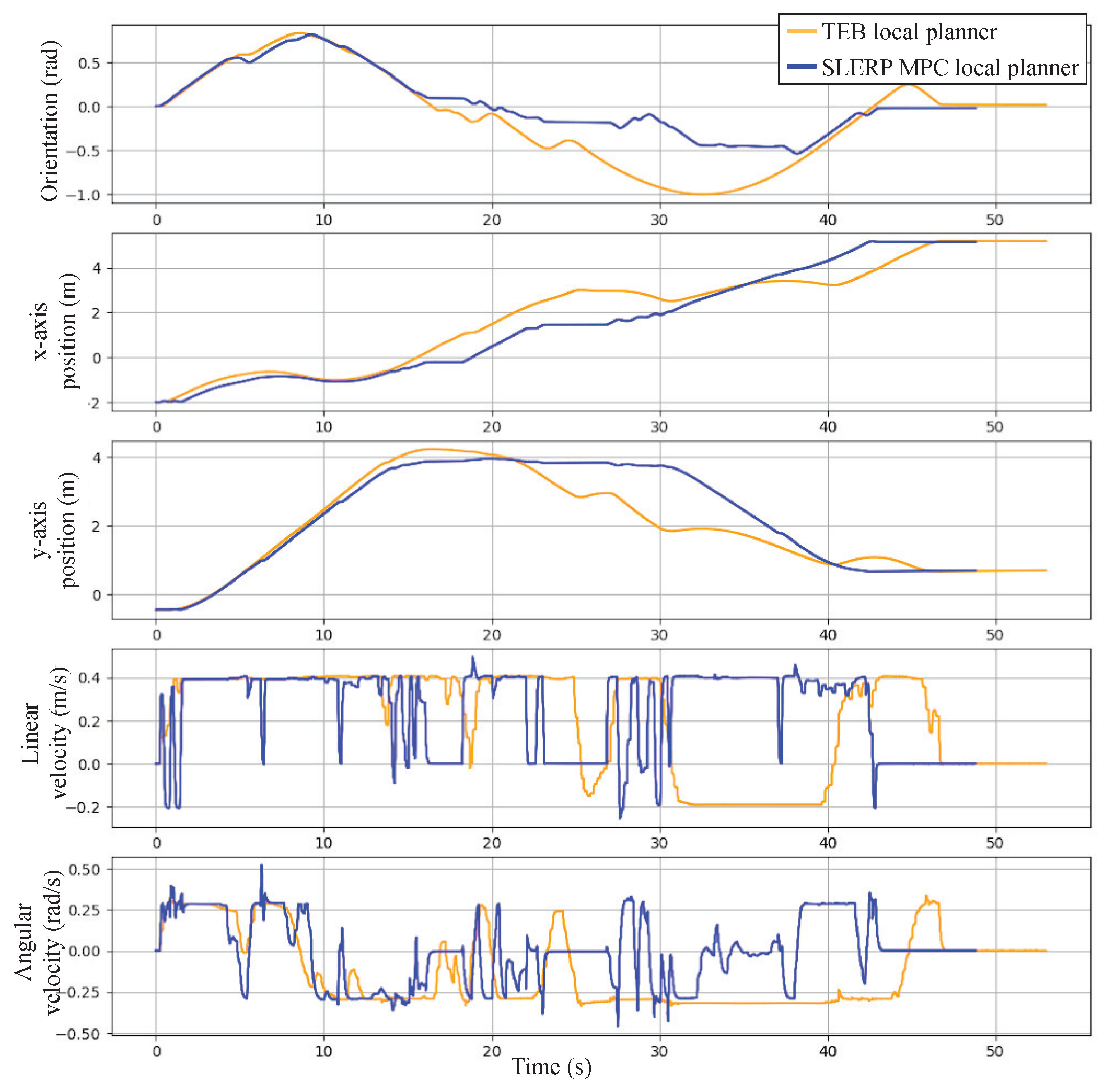
Figure 12 shows the detailed simulation results for case 2. Although the robotic wheelchair using both controllers can avoid obstacles and finally reach the target position, the wheelchair with the MPC local controller has a smaller orientation deviation and directional movement. Since the controller we designed utilizes the dual-quaternion-based SLERP and has the ability to facilitate rotation and translation simultaneously, it is reasonable for the wheelchair to approach the target more directly without unnecessary rotation.
According to the results, the proposed method can navigate the robot to the target pose safely. Although there may be errors, the simulations have proved that the method works. In general, the combination of dual quaternions and the SLERP method further enhances the control capability of the MPC local controller. The simulation results demonstrate the effectiveness and robustness of the proposed robotic wheelchair control strategy. These results highlight the potential of this control strategy to significantly improve the safety, stability, and overall performance of robotic wheelchairs in practical applications.
4.3. Experimental Results
To further demonstrate the application potential of the proposed control strategy in daily life, we also conducted real-machine experiments. The experimental evaluation is conducted using a robotic wheelchair controlled by the developed MPC-based control system. The computer configuration is as follows, CPU is Intel Core i7-12700H, GPU is RTX 3060, and MEMORY is 32GB. A specific real-world scenario is designed to validate the wheelchair’s performance. To show the results clearly, the details for some moments are demonstrated in
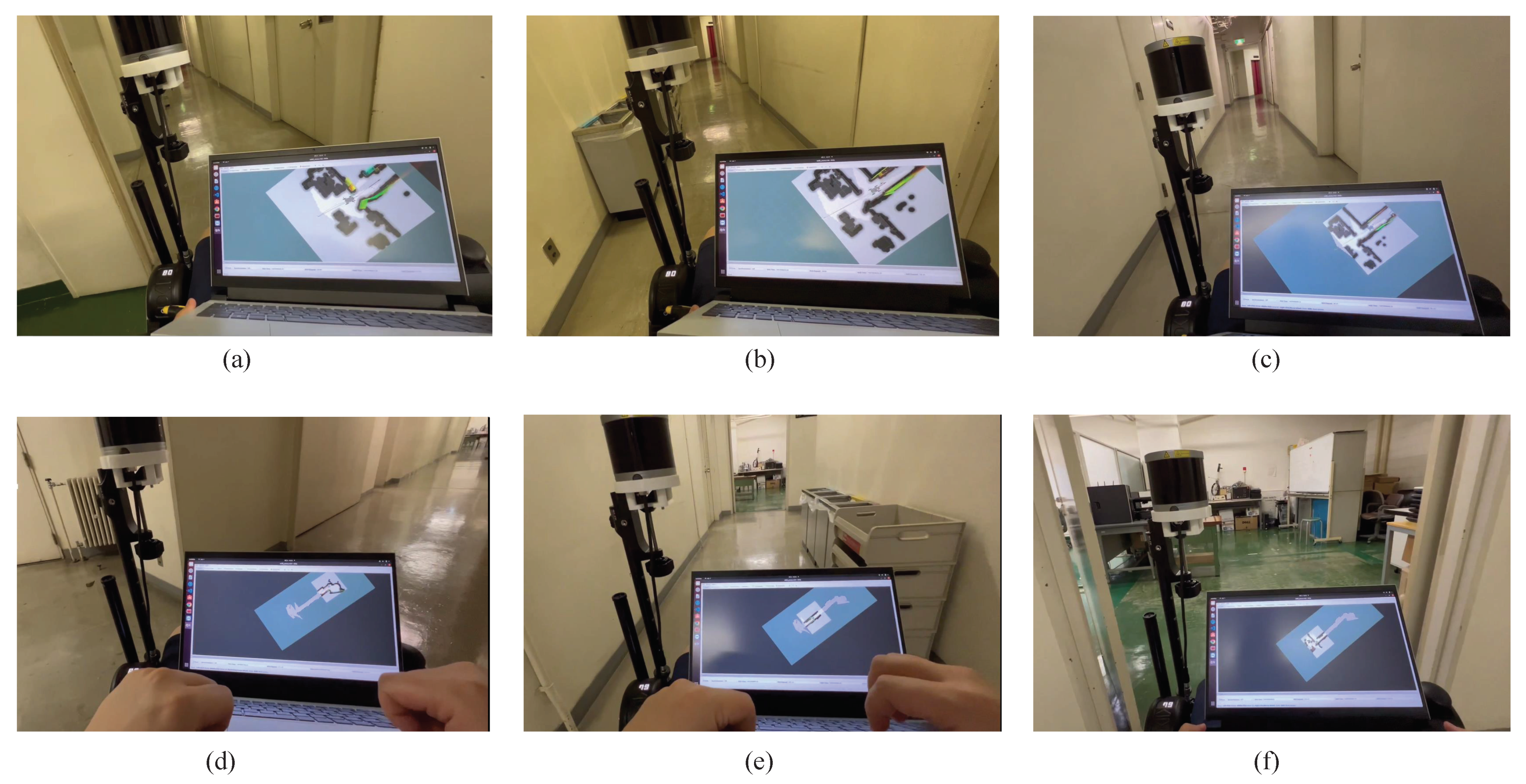
Figure 13. To better accord with real-life scenarios, we conduct practical experiments in a laboratory scenario. Our experiment begins indoors, as depicted in
Figure 13a. The map of the environment is unknown to the wheelchair. The wheelchair explores and navigates through the unknown environment with the target pose sent by the user in RViz. After successfully navigating through a doorway, the robotic wheelchair safely maneuvers through narrow corridors and avoids obstacles, as evidenced in (b) and (c). Upon reaching the corridor’s end and encountering an elevator, the wheelchair automatically executes a stable turn, as captured in (d). Subsequently, the robotic wheelchair safely and reliably makes its way back to the laboratory, as illustrated in (e) and (f). It is important to note that, for practical reasons, we intentionally avoid choosing a clean and unobstructed testing environment.
The experimental results are shown in
Figure 14,
Figure 15,
Figure 16 and
Figure 17. It can be seen that in
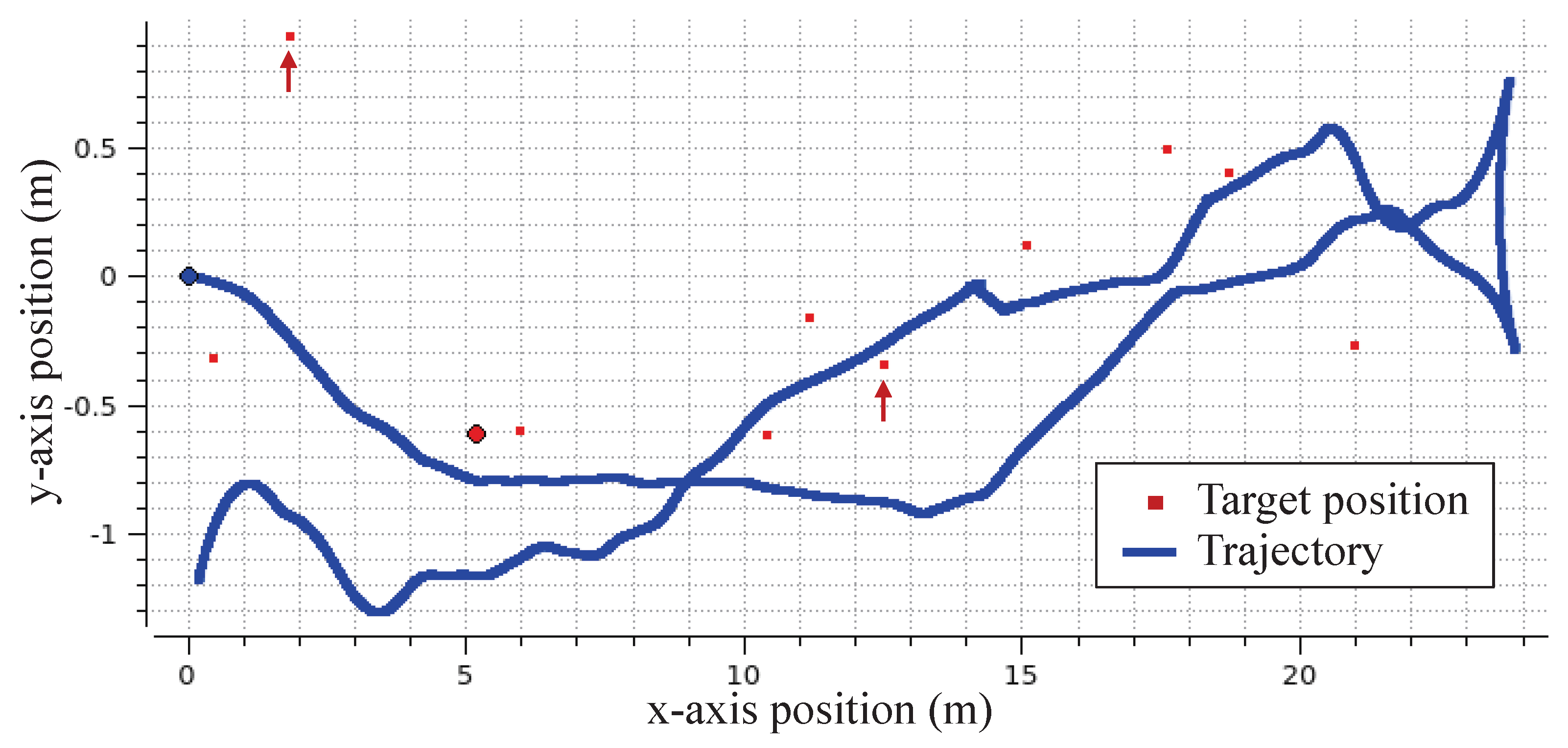
Figure 14, the initial driving origin of the robotic wheelchair is
, and the red dots are target positions sent by the user. The blue curve is the actual path of the robotic wheelchair with the dual-quaternion-based SLERP MPC controller. It is clearly shown that the robotic wheelchair can drive steadily and avoid obstacles. However, it is worth noting that two target points are outside the margin of reasonable area and have been marked by red arrows (→). This is because the experimental scenario is too narrow, and the 3D-LiDAR is unable to obtain the overall information. The target poses sent by the user may located in the walls. In
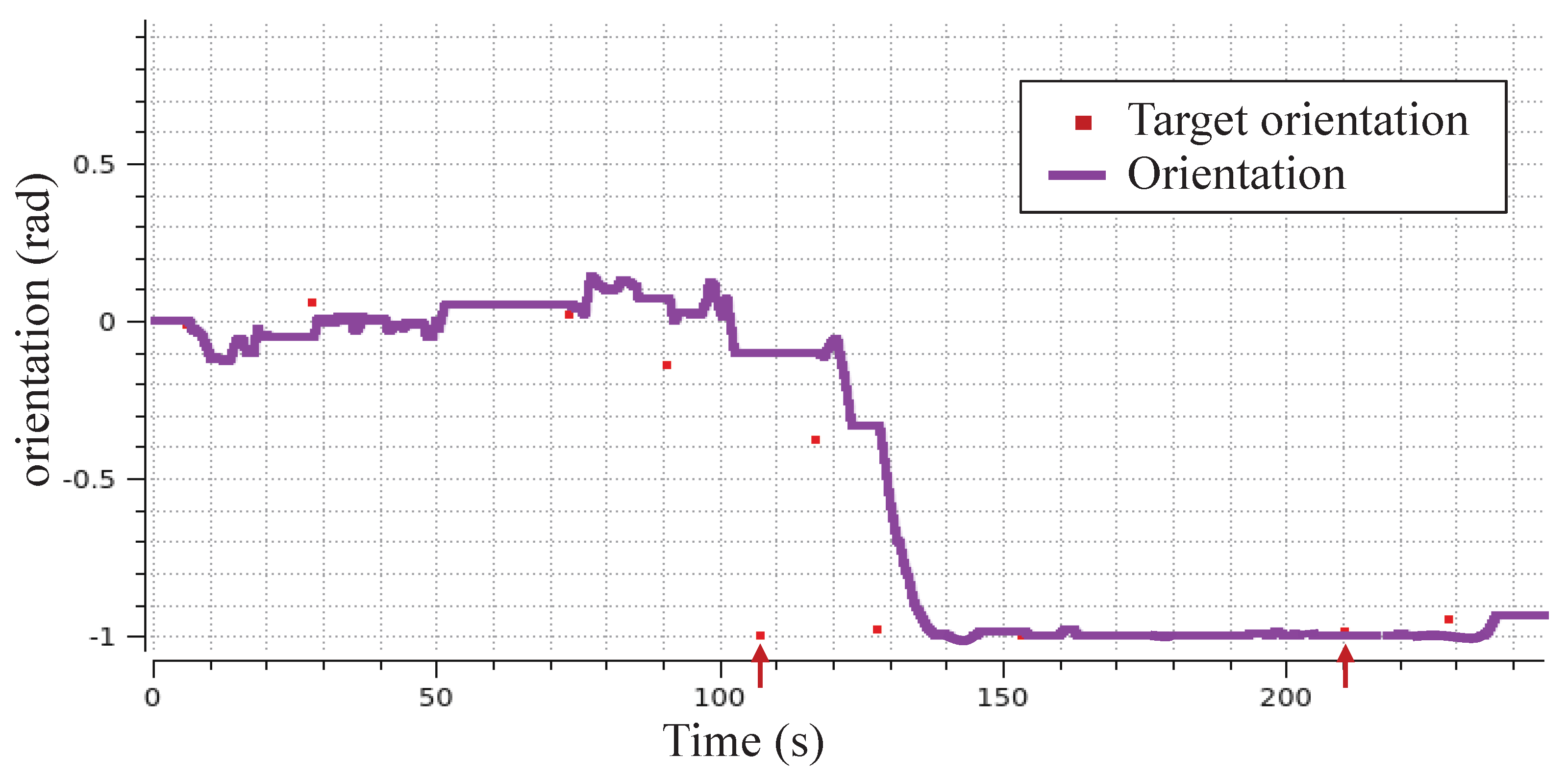
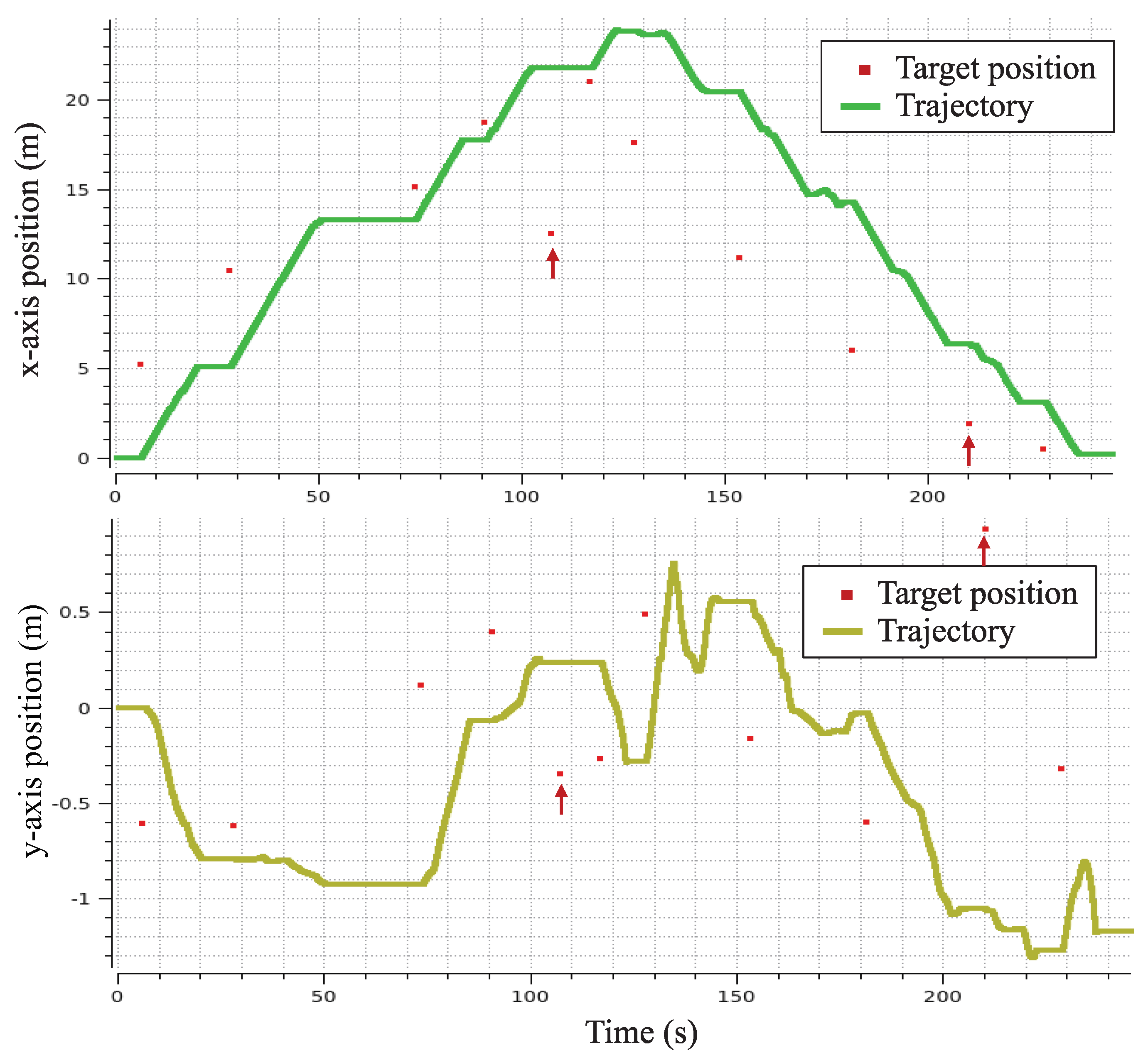
Figure 15, the purple curve represents the real orientation of the robotic wheelchair during the whole movement process. The two error points we mentioned are also indicated by arrows (→) in the figure. The real position results can be observed in
Figure 16, where the light green curve in the upper diagram is the position along the x-axis and the result in the lower shows the position along the y-axis, respectively.
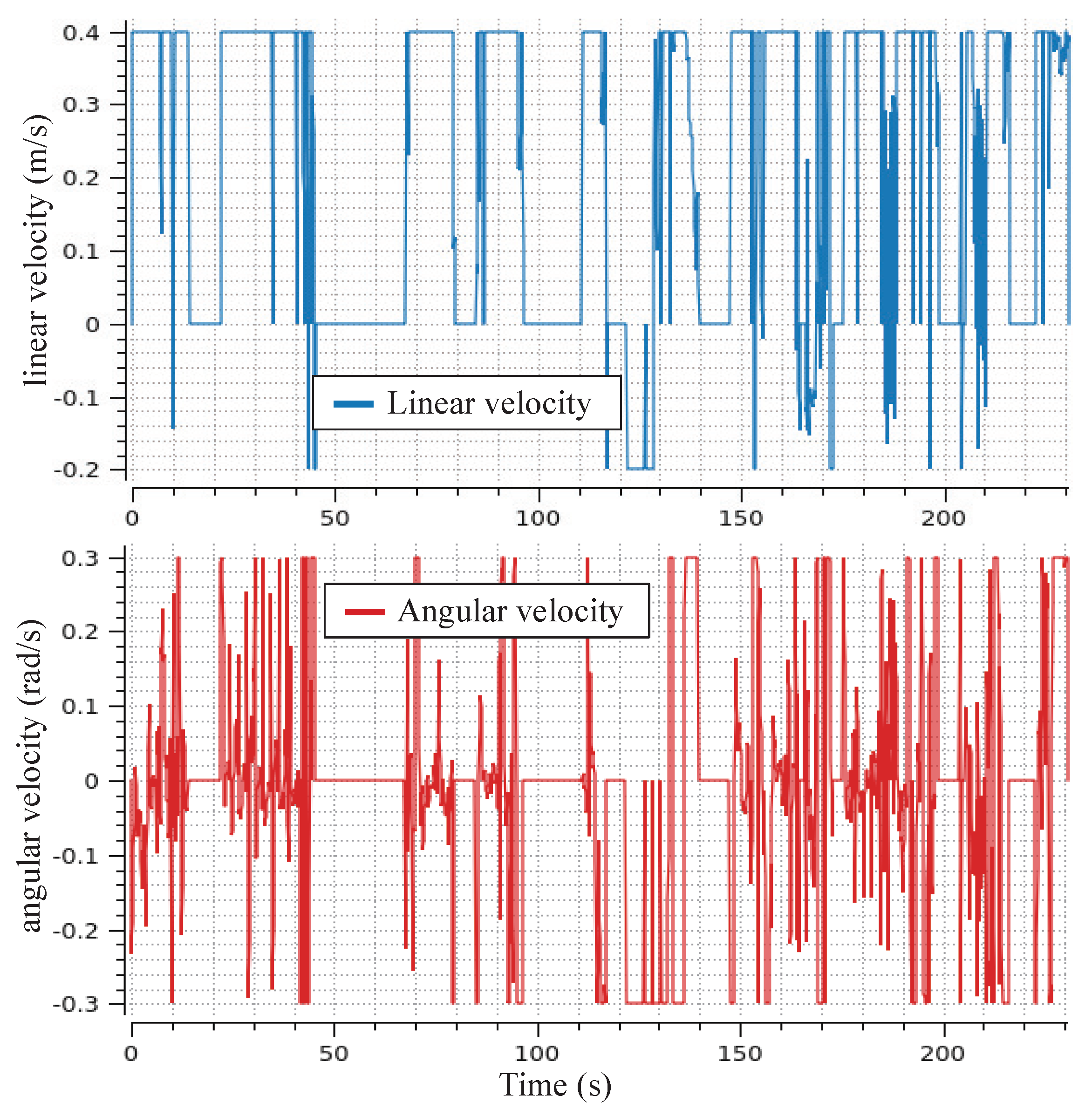
In the experiment, there is a problem worthy of our observation, that is, when the wheelchair is exiting the lab door, denoting the position in
Figure 13a, the wheelchair generates a strong bumpy feeling. In
Figure 17, the linear velocity and angular velocity change abruptly. This is mainly because the wheelchair encountered a threshold of the door when passing through the lab door. In other words, there was interference in the local map. This disturbance in the road surface also caused a bumpy feeling for the user during the movement. However, after the wheelchair crosses the threshold, it returns to the original path generated by the global path planner. This also illustrates the effectiveness of the control strategy we proposed in dealing with interference problems.
The experimental results show the practicality of our proposed controller. From all of the presented results, it can be observed that for both the simulation and experimental results, the proposed control strategy demonstrated performance. The robotic wheelchair can achieve path planning, successfully avoid obstacles, and maintain stability throughout the whole navigation process. The experiment also shows the adaptability of the proposed control strategy to actual environmental conditions, ensuring safe and efficient wheelchair movement.
4.4. Discussion
(i). Safety and stability for practical application. The simulation and experimental results clearly highlight that the use of dual-quaternion-based SLERP in robotic wheelchair control with the MPC scheme shows significant advantages and advances in terms of safety, stability, and overall performance. This method exhibits stability when tracking the target path and handling translation and rotation simultaneously, while also being adept at avoiding obstacles in real time. Such capabilities greatly improve the overall safety of robotic wheelchairs. The simulation test results in
Table 1 and
Table 2 show that although the success rates are almost the same, the proposed MPC local controller ensures a higher safety margin as it stops the wheelchair in a safe zone without collision in case of failure.
Figure 9 shows the comparative simulation result in specific failure scenarios. It clearly shows that without the MPC strategy, the robotic wheelchair hits the wall and gets stuck. In comparison, when using the proposed controller, the robotic wheelchair stops in a safe area and can restarted by a new target pose, making it more viable for real-world applications where safety and the ability to resume movement are vital. Furthermore, the dual-quaternion-based SLERP approach used in the local path planner takes advantage of its feature of handling translation and orientation simultaneously and allowing directional interpolation to ensure consistent and continuous orientation when the wheelchair approaches the target. This feature also enhances the stability of wheelchair driving, contributing to the safe and directional movement for wheelchair users.
(ii). The future potential. It is important to highlight that the critical element in evaluating the efficacy of our proposed control strategy lies in its potential for future applications. Repetitive simulation comparisons show the safety of our approach: when obstacles cannot be avoided with our controller, the robot wheelchair can stop and maintain a safe standby distance from obstacles. Once a new target pose is given, the robotic wheelchair controlled by our proposed controller can promptly resume self-driving. This addresses the effectiveness of the MPC-based hierarchical motion control system we designed to ensure the robot wheelchair’s safe operation. In particular, the experimental outcomes provide further evidence of the robustness of our proposed strategy when encountering the ground surface of disturbance. Although the wheelchair will produce an uncomfortable fluctuation when passing the threshold, it can immediately return to the desired trajectory after successfully passing the threshold and can continue to perform local searches and self-drive. This highlights the efficacy of our proposed controller in handling temporary local obstacles and disturbance problems. It also reveals the potential of our MPC-based hierarchical motion control system to tackle dynamic obstacle avoidance challenges in the future. Moreover, the use of dual quaternions in the MPC scheme, while taking into account robotic kinematics and constraints, facilitates the real-time calculation of optimal control actions. Its simultaneous calculation of rotation and translation optimizes the wheelchair’s navigation performance, facilitating safe and directional self-driving in unknown environments. For future practical applications, the robotic wheelchairs are expected to assist elderly users with mobility issues in different scenarios, such as facing toward the table for meals or approaching beds for sleep. The directional movement realized by the proposed controller can give intuitive feedback to the users and improve their life quality.


