Article

Robotic Writing of Arbitrary Unicode Characters Using Paintbrushes

by
David Silvan Zingrebe
,
Jörg Marvin Gülzow
*,† and
Oliver Deussen
Department of Computer and Information Science, University of Konstanz, 78457 Konstanz, Germany
*
Author to whom correspondence should be addressed.
These authors contributed equally to this work.
Robotics 2023, 12(3), 72; https://doi.org/10.3390/robotics12030072
Submission received: 4 April 2023 / Revised: 5 May 2023 / Accepted: 9 May 2023 / Published: 11 May 2023
(This article belongs to the Section Sensors and Control in Robotics)

Abstract

:
Human handwriting is an everyday task performed regularly by most people. In the domain of robotic painting, multiple calligraphy machines exist which were built to replicate some aspects of human artistic writing; however, most projects are limited to a specific style of handwriting, often Chinese calligraphy. We propose a two-stage pipeline that allows industrial robots to write text in arbitrary typefaces and scripts using paintbrushes. In the first stage, we extract a set of strokes from character glyphs which are similar to how humans choose strokes during writing. In the second stage, we generate corresponding brush trajectories by applying a brush model to the extracted strokes. Our brush model computes the required brush pressure to achieve the given stroke width while also accounting for brush lag. We also present a method to automatically measure the parameters needed to predict brush lag by painting and recording calibration patterns. Our method generates trajectories for text in any given typeface, which, when executed by a robotic arm, results in legible written text. We can render most writing systems, excluding emoji and ligatures, in which arbitrary texts can be specified to write.

1. Introduction

Human writing is a quintessential task in day-to-day life used to record information and communicate. It can also be a kind of artistic expression in the form of calligraphy, where brushes are commonly used. Since we already possess robotic painting systems which use brushes for painting images, they can be extended to write using their existing tools. Unfortunately, brushes are fundamentally imprecise tool which exhibit hard to predict behavior. In writing in particular, small deviations can spoil the overall impression of some letters or even make the piece of writing unreadable. For humans, learning to write with simpler tools, such as pencils or pens, at an acceptable level takes many years of practice during childhood. With brushes, the difficulty rises significantly; in Asian calligraphy, students require a lot of practice to master the complex brushes [1].
Therein also lies the scientific challenge of handling soft tools like brushes; for robotics, rigid and easy to predict tools are preferred. When humans handle soft tools, they can benefit from real-time feedback and experience in handling physical objects. For automating writing with brushes, a model to observe, measure, and predict brush behavior is required.
We developed the e-David painting robot, which is able to paint pictures by using a brush to apply paint to a canvas [2]. In the painting process, we use knowledge about brush dynamics to increase our tool precision. We wish to extend the e-David platform to also be able to create writing automatically using the existing brush tools. The focus lies on producing legible results for arbitrary text, written in an arbitrary font, as opposed to mastering a single style of writing. For this we can make use of our optical feedback system to guide stroke placement.
In writing, the atomic building block is called a grapheme. Following the rules of the grammar of a language, graphemes can be combined to form complex text. Depending on the underlying language or script, the direction of writing may change. While most languages are written from left to right and top to bottom, many Asian scripts are written from top to bottom and right to left. Naturally, there are many different writing styles of a script. In typography, writing styles are called typefaces, which are usually called fonts on computers. A font is a collection of glyphs for one or more scripts where a glyph is the graphical representation of a grapheme. A font may store glyphs as bitmap images or as a set of outlines of said glyph. A font may also provide different glyphs for a single grapheme for its variations, such as italic and bold, or simply for better legibility at different text sizes.
The process of robotic writing can be divided into two parts. First, to be able to write text, the glyphs used in the text need to be segmented into sets of strokes, which should be similar to the movements used by humans to realize the corresponding letters. While humans are taught the elements of characters and the order in which to realize them early on, it is not a trivial task for computers to segment given glyphs into strokes without additional knowledge. Usually, font definitions do not contain any information relevant for painting, such as sub-elements of a glyph, realization order, or stroke centerlines. Instead, they are a set of curves describing the outlines of glyphs. Despite this, methods exist to convert them back into subunits, which we apply to extract movements from a glyph. Second, the computed glyph components must be realized on the canvas at the right location relative to the other text components. However, paintbrushes are compliant tools and simply painting along the centerline of a glyph component will not precisely replicate it. Bristles bend while the brush is pulled along the canvas and deform with varying applied pressure. Simply following a centerline, for example, will lead to blunted corners and offset curves. Brush trajectories must be modified to compensate for brush dynamics and to produce a satisfying result. Humans can learn the behavior of the brush such that they can adjust the trajectory on the fly. For robots, a physical model of the brush is required to generate suitable trajectories. For this purpose, we can make use of the fact that brushstrokes are repeatable [3], allowing us to derive brush parameters from known strokes; we draw a calibration pattern consisting of semicircles of varying radii which are recorded by our optical feedback system. By comparing the pattern to the resulting brush footprint we can determine the amount of compensation needed for different features.
Some work on this has been performed before for Chinese and Japanese calligraphy, where brushes with very long bristles are used to write with ink on special paper [4]. In our method we take a more general approach and use regular painting brushes and do not place restrictions on the canvas or paint type. Furthermore, we can paint any textual glyph, making our system largely language-independent.
The overall goal of this work is to create a modular and flexible pipeline for writing text with robotic arms in arbitrary typefaces with little to no required knowledge about either the text to be written or the typeface used. Our main contributions are the development of a calibration procedure to measure brush lag in curved strokes and the application of the derived model to writing brushstrokes, increasing their precision.

2. Related Work

e-David (Electronic Drawing Apparatus for Vivid Image Display) is a painting robot project at the University of Konstanz. The original goal of the project is to simulate the human painting process by repeatedly taking an image of the current canvas and deciding where to place further strokes accordingly [5]. The current setup features an industrial welding robot placed next to a painting surface to which multiple canvases can be attached. A camera system provides optical feedback for the painting process, enabling it to paint iteratively and to record painting results for brush parameter measurements [3,6]. One e-David setup can be seen in Figure 1.
The representation of fonts in computers have developed from using low resolution bitmaps, which were later replaced by outline fonts, such as TrueType or OpenType [7]. They use line segments or Bézier splines which are rendered as needed for varying output devices. Another system, MetaFont, was proposed in [8], which, instead of explicitly storing the outline of glyphs, represents them using only strokes and corresponding stroke widths.
A method for extracting paintable centerlines from outline fonts is the Voronoi medial axes (VMA) method, proposed by Ogniewicz et al. in [9]. They define multiple residual functions that correspond to the importance of a node on the medial axis. Unwanted branches in the VMA can be removed by thresholding the VMA nodes against computed residuals. The resulting VMA is a medial axis where branches that do not contribute to the shape of the input have been removed. Small branches are a major hurdle in robotic writing as they can lead to unwanted artifacts.
While most scientific works aim to achieve the best-looking writing results, a mathematical model was built by [10] that reproduces the biomechanical principles of human muscle fatigue. The model can be applied to stroke trajectories to transform them into strokes that provide the appearance of as if they have drawn by a tired human.
The most recent methods in robotic writings use general adversarial networks (GANs) to achieve a specific style in basic strokes of Chinese calligraphy characters [11,12,13].
A self-learning system for Japanese and Chinese robotic calligraphy was introduced by [14]. In their setup, a stroke is loaded from a database and executed either in a simulation or by a real robot. The resulting error is computed and the stroke trajectory is adjusted accordingly to improve future results. This process is repeated until the error becomes sufficiently small.
There has been a lot of research on virtual brush painting [15,16,17]. Virtual brush models use a physical simulation of bristles on the canvas to create virtual images of the resulting pictures. The models can be used to play around with and study the behavior of painting brushes. However, since the virtual brush models do not exactly correspond to any real-world painting brush, they can not be used to improve trajectory generation for robotic writing.
A modern and more artistic form of writing is graffiti. A model for drawing graffiti on a compliant robot is described in [18]. Robotic graffiti is more driven by kinematics, where a flowing style is preferred over exact reproduction or even legibility. As such, Berio et al. directly control the joints of the used robotic manipulator, as opposed to using a kinematic solver, which moves the end effector from point to point.
A similar painting system to e-David has been developed by Scalera et al. which also consists of a six-DoF robotic arm which applies a paintbrush to a canvas. In [19], they present a system which applies non-photorealistic rendering (NPR) techniques, such as from hatching to robotic painting. By combining NPR with path planning and incorporating brush dynamics measurements, they produce detailed, sketch-like paintings.
Beltramello et al. use a palette knife instead of paint brushes to create paintings. This is a rigid tool often used by human artists, and they propose several techniques to incorporate the unique marks made by the knife into the resulting image. Their system can create larger marks as well as thin detail lines [20].
Karimov et al. designed and built a new robotic painting system with their publication emphasizing the mechanical design of the machine. Their machine is a three axis gantry setup, similar to a CNC router, which moves a brush with an attached paint mixing system. The mixing system consists of syringes which force paint through the back of the brush, based on computations from a color mixing model. Extensive work has also been performed to ensure proper cleaning of the brush to avoid cross-contamination. Karimov et al. do not use any visual feedback for now and use a modified Hertzmann algorithm for stroke generation [21].
Another Cartesian painting robot is presented by Igno-Rosario et al., for which they use interactive segmentation to identify paintable regions. They further augment these regions with user-defined orientation fields, which guide stroke placement and show result images consisting of tree to five regions [22].

3. Methods

Our system takes a text to be written and a typeface (font) as input. First, we sample the outlines of each glyph and convert them it to a set of line segments, which represent glyph outlines. The samples are used to build a Voronoi diagram which, in turn, is used to generate the Voronoi medial axis (VMA) of the glyph, which approximates the glyph’s centerline skeleton. We remove unwanted bifurcations through normalizing the VMA [9], resulting in a graph approximation of the strokes that are required to write the glyph. A modified depth-first search (DFS) then ranks all possible strokes in the graph based on their writability and a list of writable strokes is extracted by repeatedly selecting the most writable stroke from the graph until all trajectories are accounted for. The strokes for each glyph are translated and scaled to their canvas position and kerning is applied. Next, we modulate the trajectories using the brush model to account for brush lag and to compute the required pressure in each point to achieve then necessary stroke width. A final smoothing pass filters out unwanted rapid robot movements and the computed paths are sent to the machine to be executed. The overall writing process is summarized in Figure 2.
In the following text we use the term “pressure” to refer to the vertical distance of the Tool Center Point (TCP) relative to the painting surface. The painting robot is set up such that the brush tip is coincident with the TCP. In tool coordinates, the canvas surface is defined as z = 0 mm. In order to apply the brush to the canvas, the TCP is moved behind the canvas surface, by a given amount in millimeters. Because of previous work completed in [3] a known relationship between this distance and the resulting stroke width (also in millimeters) exists. Due to this, we refer to the z-coordinate of the TCP relative to the canvas as “pressure”, given in millimeters, since it corresponds to the intuitive concept of brush application pressure, despite not really being a force.

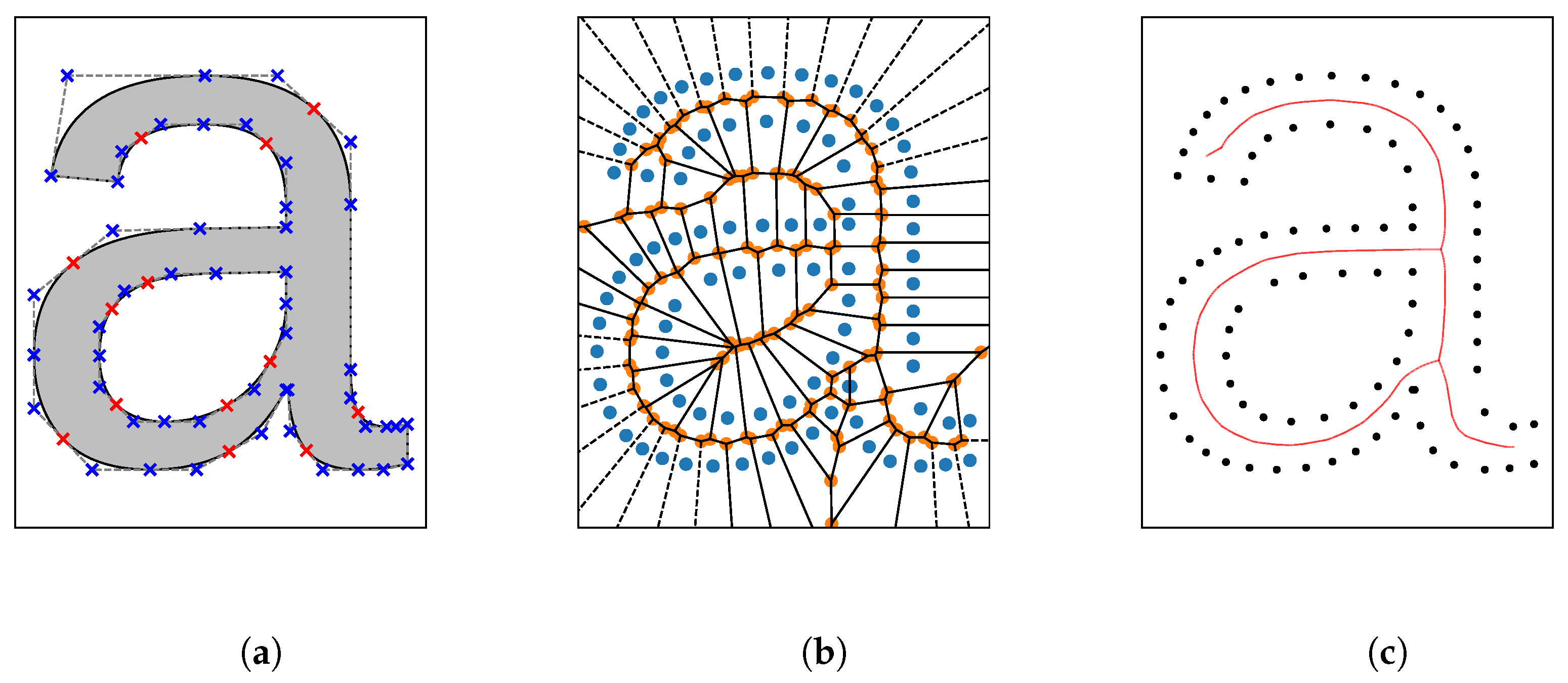
3.1. Glyph Skeleton Extraction

Since glyphs are not trivially paintable, we need to extract a set of paintable strokes. The goal is a set of strokes of the form p 1 , , p n , where each point p i = ( x i , y i , w i ) consists of a 2D canvas position ( x i , y i ) and a stroke width w i . To find a suitable glyph centerline we generate a Voronoi diagram from the sampled contours which, in turn, is used to extract the Voronoi medial axis (VMA).
We first sample the glyphs contours individually. Each contour is made up of the juxtaposition of Beziér curves where the start of the first curve is the end of the last curve, thus forming a loop. Thus, the samples of the contour can be computed by sampling its individual Beziér curves. Figure 3a shows the letter “a” in its Beziér outline form, with blue markers representing Beziér control points provided by the font library and red crosses indicating implicit control points which are omitted in the font specification.
Given the sampled contours, we compute a Voronoi diagram of all samples using the SciPy library. The SciPy library additionally provides a graph whose edges represent borders between two regions in the Voronoi diagram and nodes are the intersections of two or more borders between regions. The borders of the Voronoi regions are located such that they are at a maximum distance from any outline sample, thus they can be viewed as the centerline between outline samples. Additionally, because each node in the graph is incident to at least one edge, each node lies on a centerline between two points of the outline. The distance from a node in the diagram to its closest outline sample, therefore, represents the radius of an inner circle within the glyph touching the contour on at least two points. We thus associate the node with the glyph width at that position. The result of such a Voronoi diagram is shown in Figure 3b, where the outline samples are colored blue, the borders of each cell are solid black lines and intersections of region borders are marked orange.
While the skeleton of the glyph is already visible to the human eye the graph of the Voronoi diagram still contains nodes that are outside the glyph. For each node in the graph, we perform an even-odd test to determine whether it lies inside the glyph or not and remove all outside nodes together with their incident edges. The resulting Voronoi graph describes the medial axis, i.e., the VMA. We normalize the VMA using the method described in [9] using the proposed chord residual as the residual function. As a threshold for removing spurious and unwanted branches from the VMA we chose the value 15 for common Latin scripts and 8 for more complex Asian scripts. The normalized VMA yields a medial axis (skeleton) of the glyph. The medial axis of the character “a” is shown in Figure 3c.
One problem with Voronoi medial axes often occurs in areas of intersection within a glyph. While the intersection appears obvious to the human eye, the VMA may contain more than just a single node of degree greater than two in place of the intersection. An example of such a problematic intersection is shown in Figure 4a. We fix these intersections by first identifying nodes of degree greater than two and call them intersection nodes. For each intersection node we determine all other intersection nodes reachable over a path of distance d d t in the VMA where d t is a fixed distance threshold. This way we can partition the set of all intersection nodes into intersection groups G i , such that intersection nodes n , k G i if there is a path of distance less than d t between n and k in the VMA. We compute the intersection neighborhood N i for each G i , such that n N i if n G i or n is a node on a path of distance d d t between two nodes n , k G i . In Figure 4, we show an example of this with the nodes in N i highlighted red.
To fix the intersection for a given intersection group G i in the VMA, we first compute all nodes connected to the intersection group that are not part of it.
C i = { n VMA n G i }
We then remove all nodes n G i from the VMA and insert a single representative r i for the group whose position and stroke width is the average of the nodes in G i . Finally, we connect the representative r i with all previously connected nodes by adding the edges { r i , n } for all n C i to the VMA. The result of this operation is shown in Figure 4b.

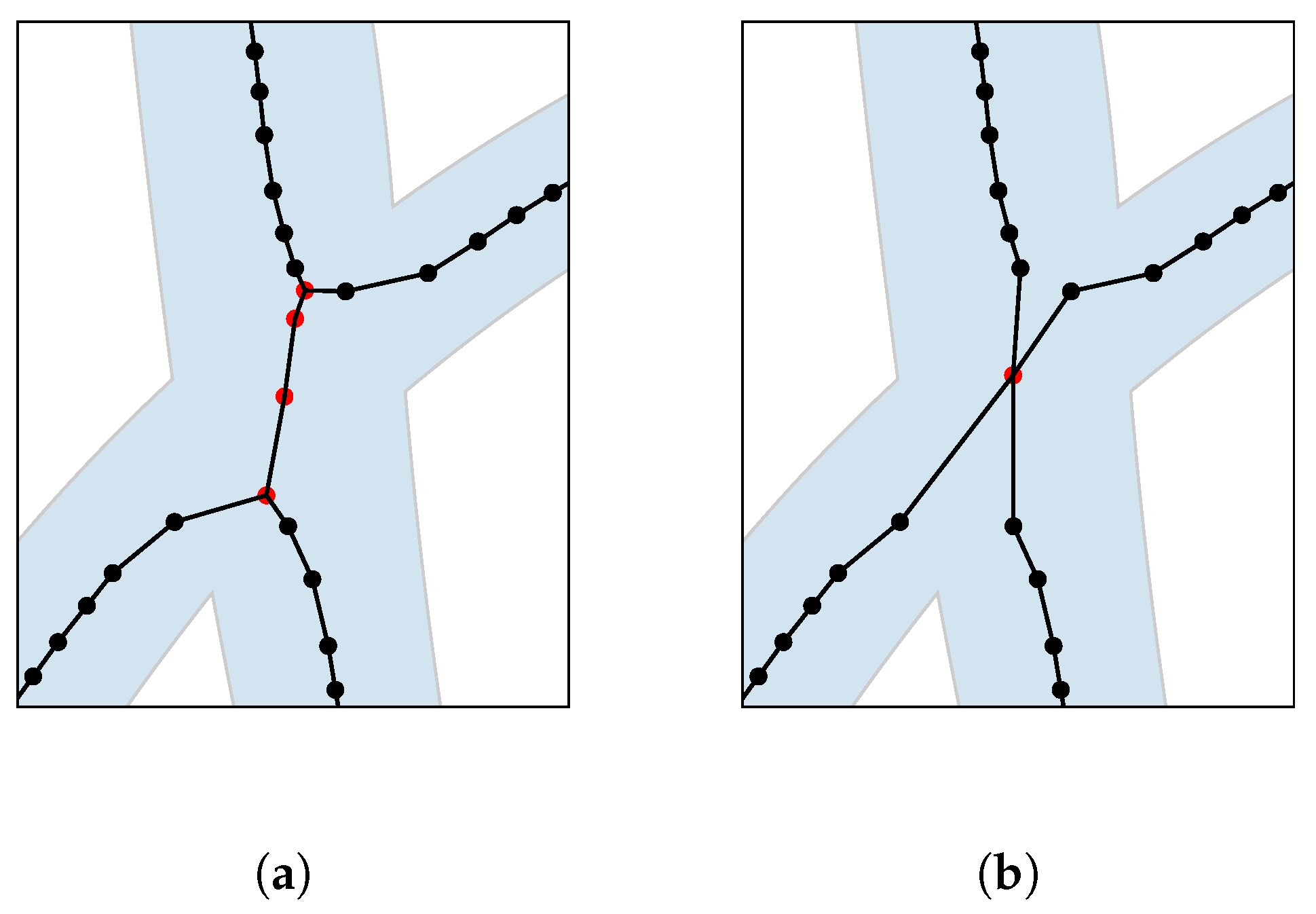
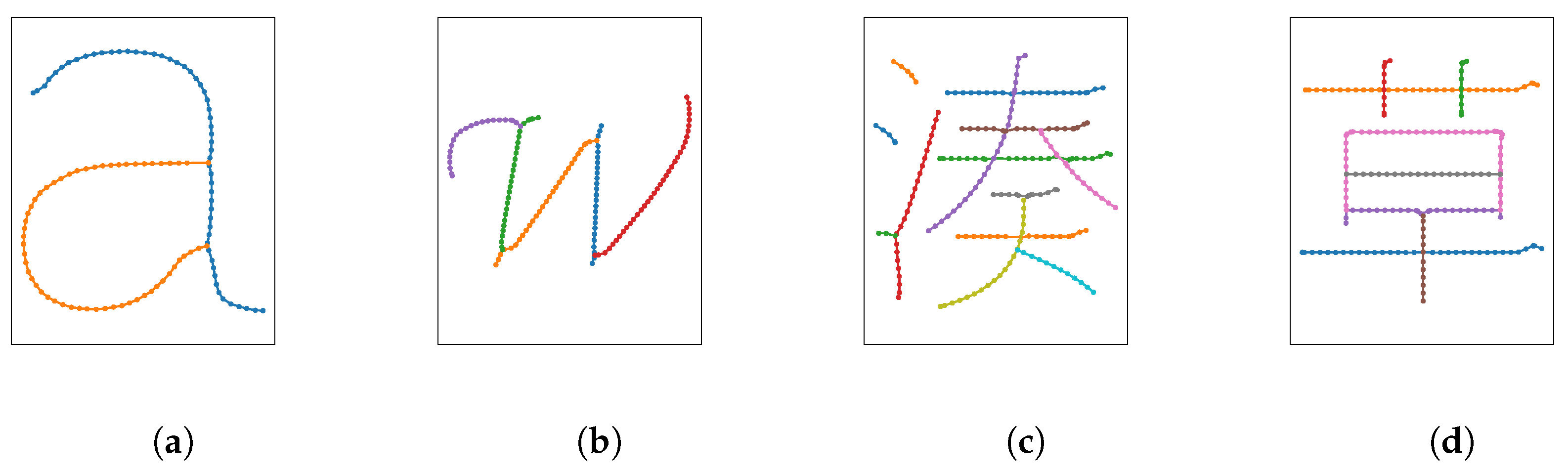
3.2. Stroke Computation

The computed medial axis of the glyph is a graph, which can contain an arbitrary number of branches and, thus, cannot directly be drawn. Therefore, we extract a set of strokes from the medial axis that, when combined, form said glyph. The nodes of degree one in the medial axis are the start and end points of strokes and we select them as candidates to start stroke movements. We rank strokes and choose the best possible stroke greedily according to measures such as curvature.
First, we extract candidate strokes by applying a modified depth-first search (DFS) to the medial axis. Candidate strokes are strokes made up of the nodes on the current path at the point where the DFS needs to back-track due to thre being no possible way to continue. Instead of marking visited nodes during the DFS, we instead mark traversed edges that cannot be used again further down the DFS. This allows us to extract strokes that self-intersect at a single node but forbid strokes to use an edge twice.
Let w = ( x 1 , y 1 ) , , ( x n , y n ) be the positions defining a candidate stroke found by the DFS. The vector between two adjacent points of the stroke is given as
( x i , y i ) = ( x i + 1 x i , y i + 1 y i )
where 1 i < n . We define the following k-window curvature for a given stroke:
C ( w , k ) = 1 n 1 i = 1 n k 1 j = i i + k 1 atan 2 ( x j y j + 1 x j + 1 y j , x j x j + 1 + y j y j + 1 )
C can be seen as a moving window average of size k over angles between two adjacent edges between points in the candidate stroke. We further define a ranking function that averages the k-window curvature of a stroke over multiple window sizes k 1 , , k p .
r a n k ( w ) = 1 p i = 1 p C ( w , k i )
We use windows of size 4 , 8 , and 16.
We remove the candidate stroke of minimal rank from the medial axis graph and add it to a set of strokes for that glyph. This process of finding, ranking, and removing candidate strokes is repeated until the medial axis is empty.
The strokes extracted from the VMA are lists of two-dimensional points and corresponding glyph widths. Figure 5 shows the results of extracting individual strokes from the VMA.
We extracted strokes for each glyph in the text separately. Coordinates and widths are still in a virtual space. To arrange the strokes to form a proper piece of text, they are simply translated one after another according to the metrics defined within the font file. The arranged text is then mapped from the virtual space right onto the target area on a canvas in real word space measured in millimeters.

3.3. Brush Trajectory Generation

We use our method, as described in Section 3.2, to extract brush strokes from glyphs. However, accurately painting the desired strokes using a brush is not trivial. Simply executing the strokes on the robot results in footprints differing noticeably from the desired result because neither do we know how much brush pressure is needed to achieve a given footprint width, nor do we account for brush lag caused by the bending of the brush on the canvas.
While moving over a canvas surface, the brush lags behind in the opposite direction of the direction the brush is moving along its trajectory. Additionally, the tangent along the centerline of the brush footprint approximately intersects the brush trajectory at the point where the robotic arm holds the brush. Analogous, given the position of the brush tip on the centerline of a footprint, we can compute the brush position on a corresponding trajectory by extending the point along the tangent by some amount of brush lag [23].
We represent strokes as lists of points, each consisting of a two-dimensional position and stroke width. To construct a brush trajectory that corresponds to a specific stroke we correlate the stroke width with the pressure depth required to achieve said width. Let s = s 1 , , s n be a stroke defined by n control points s i = ( p x , i , p y , i , w i ) given by their two-dimensional positions and target widths. We transform the stroke s into a trajectory t = t 1 , , t n of n control points where t i = q x , i q y , i q z , i T are positions of the trajectory in three dimensional space. We transform all points of a stroke into points of a corresponding trajectory by extending each point in the current drawing direction and applying a pressure model:
t i = p x , i + L ( s , i ) · d x , i p y , i + L ( s , i ) · d y , i P ( s , i )
where d i = V i | | V i | | , V i = ( p x , i p x , i 1 ) ( p y , i p y , i 1 ) T is the unit length stroke direction at control point i and L ( s , i ) is a function for the lag distance at the i-th control point. P ( s , i ) is a function of the required pressure to achieve the required footprint width w i at the i-th point of the stroke and has been reused from [3]. Lag is an offset of the brush tip from the actual tool position which results from brush movement. Since, at the first point, the brush did not experience any movement there is no brush lag and we define L ( s , 1 ) = 0 .
Without further analysis, choosing a constant brush lag distance L ( s , i ) = d already causes observable improvements in the resulting stroke (see Section 4). The lag distance d can be measured by hand by measuring the distance between the brush position and its tip as the brush is drawn over a surface. The pressure P ( s , i ) required for a given width w i may be computed using a linear regression, as described in [3]. However, since the lag distance of a brush generally is not constant but depends on multiple variables, such as the pressure applied to the brush and local stroke curvature, we perform a more advanced analysis of the behavior of a brush under different pressures and radii to compute a more precise model of L ( s , i ) and P ( s , i ) . To avoid blobs of ink we additionally limit the brush pressure at the start of each stroke instead of simply lowering the brush vertically onto the canvas. We discuss these methods in more detail in the following sections.

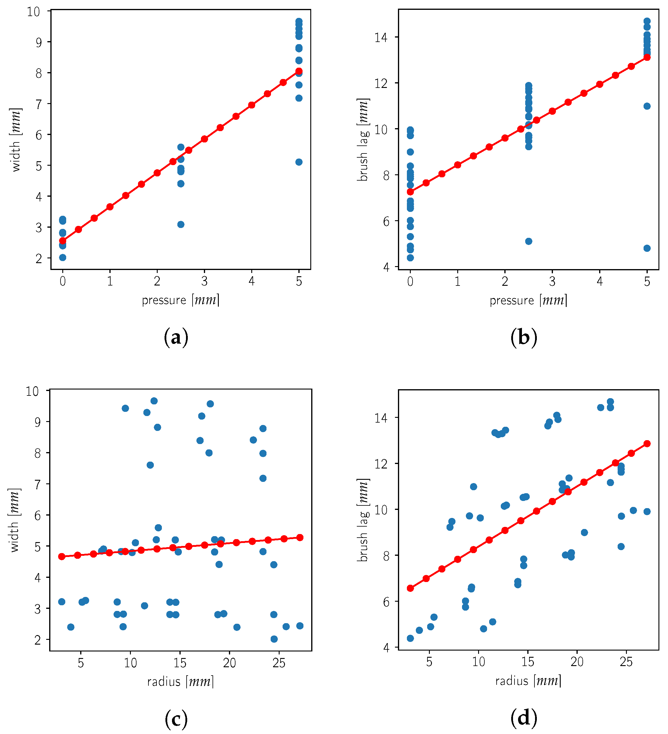
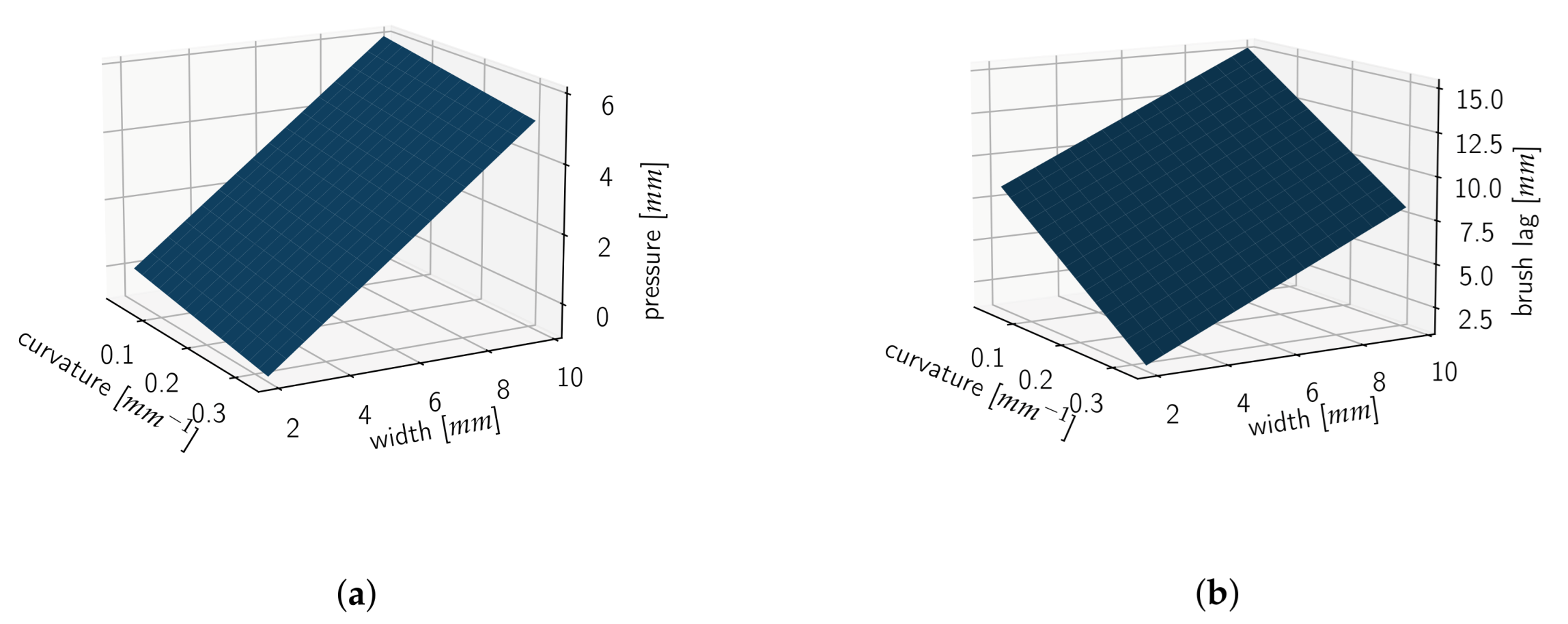
3.3.1. Brush Behavior Modeling

A brush has a minimum pressure at which its tip barely touches the canvas and a maximum pressure at which it can be used without breaking. Additionally, the curvature of drawn strokes tends to lie in a very limited range (i.e., the radius of a fitting, or kissing, circle is limited to a small range). We choose a set of pressures and radii from those ranges. For each combination of pressure and radius ( p , r ) we generate the brush trajectory of a semicircle of said pressure and radius as shown in Figure 6a. We translate the resulting trajectories along the canvas with enough margin, such that the resulting stroke footprints do not overlap. Each trajectory ( p , r ) is placed on the canvas multiple times to account for noise in the drawing process. While drawing, the brush is dipped into paint before each stroke and an auxiliary wipe is performed off-canvas to avoid excessive paint application. This ensures a consistent brushstroke result for each semicircle. After painting the trajectories an image of the resulting canvas is taken using the visual feedback mechanism. An example is shown in Figure 6b where the radius of the semicircle increases to the right and the brush pressure stays constant. Each column is a replica of the trajectories, yet minor differences between the resulting footprints become visible. Strokes of different pressures were executed analogously on additional canvases. A trajectory for a 15 mm radius semicircle and its resulting footprint are shown in Figure 6c. The canvas feedback image is corrected for lighting differences and then binarized, yielding a pixel image with clear stroke footprints (Figure 7).
Since we want to extract information such as brush lag and width from the stroke footprints we skeletonize the resulting binary image using the method described by [24]. This yields an image where each stroke is skeletonized to one pixel wide lines. We then generate a skeleton graph G s k e l = ( V , E ) whose vertices correspond to the pixels of the skeleton
V = { ( x , y ) ( x , y ) is on the skeleton }
and adjacent skeleton pixels are connected by an edge
{ v , v } = { ( x , y ) , ( x , y ) } E v , v V | ( x x ) | , | ( y y ) | 1 .
For each semicircle we determine the vertices v s , v e G s k e l closest to its trajectories starting and ending points. We find the shortest path v 1 , , v n in G s k e l where v 1 = v s v n = v e . This path represents the stroke centerline. An exemplary skeleton is shown in Figure 8a. Then, we determine the middle vertex v m = ( x m , y m ) of the centerline and two other vertices v f = ( x f , y f ) , v b = ( x b , y b ) at reasonable distance d from v m in forward and backwards direction of the stroke. We use the vertices v m , v f , v b to fit a kissing circle to the strokes centerline at v m . Let
m = x m + i y m f = x f + i y f b = x b + i y b
be the three imaginary numbers corresponding to the pixel positions of the three vertices v m , v f , v b . Furthermore, let w = b m . Then, the center of the kissing circle at v m is given as
c = m w | w | 2 2 i · Im ( w ) · ( m f )
where w = b m f m . The radius of the circle is given as r = c m . Figure 8b shows the three vertices v m , v f , v b on the centerline and the resulting kissing circle together with its center.
We compute the stroke width at v m by sampling a ray along the normal of the kissing circle in both directions. The distance between the two intersections with the strokes contour is the stroke width, as shown in Figure 8c. Similarly, we compute the brush lag by finding the intersection of the kissing circles tangent in v m with the original brush trajectory. The distance between v m and the intersection is the brush lag distance as indicated by the red arrow in Figure 8d. Since the computations are performed on pixels in image space and not in world space, we multiply the extracted values by the ratio of millimeters per pixel in the image. To denoise the results we average them across a range of distances 5 mm d 10 mm.
For each collected footprint, we save the brush pressure, the radius of the kissing circle at the centerline midpoint, and the measured stroke width, as well as the brush lag distance. We show the measured footprint width and brush lag distance in Figure 9. In Figure 10, we show the correlation between the various variables.
From Figure 10a,b, we observe that the pressure applied to the brush while painting strongly correlates with both the resulting footprint width and the experienced brush lag distance. From Figure 10d, we see that the curve radius also correlates with the brush lag distance; however, the radius does not affect the resulting footprint width (Figure 10c).
As the measured data show obvious correlations between the different variables, we perform a linear regression. We use the curvature and footprint width as explanatory variables. The brush pressure and lag are the dependent variables we want to predict. We use a curvature measure defined as the reciprocal of the radius c = 1 r since straight lines, which occur in most glyphs, have a radius near to infinity, blowing up any predictions from the linear regression. Our resulting model for a DaVinci College 4 brush is shown in Figure 11.
Given a control point s i = ( p x , i , p y , i , w i ) of a stroke s, we use the stroke width w i as input for the model. We obtain the curvature at that point similar to the above by choosing its two neighboring control points s i 1 , s i + 1 and using the positions of those three points to compute a corresponding circle. The curvature c i at s i then is the reciprocal of that circle. In case the control point does not have neighbors, we define its curvature as zero. Given the stroke width and curvature of a point s i , we apply our regression model and use the predicted brush pressure and lag as P ( s , i ) and L ( s , i ) in Equation (1). We obtain a brush trajectory t corresponding to the stroke s by applying this step to all control points s i of s.

3.3.2. Brush Approach Correction
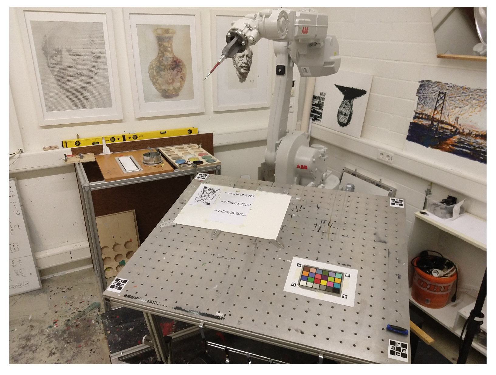
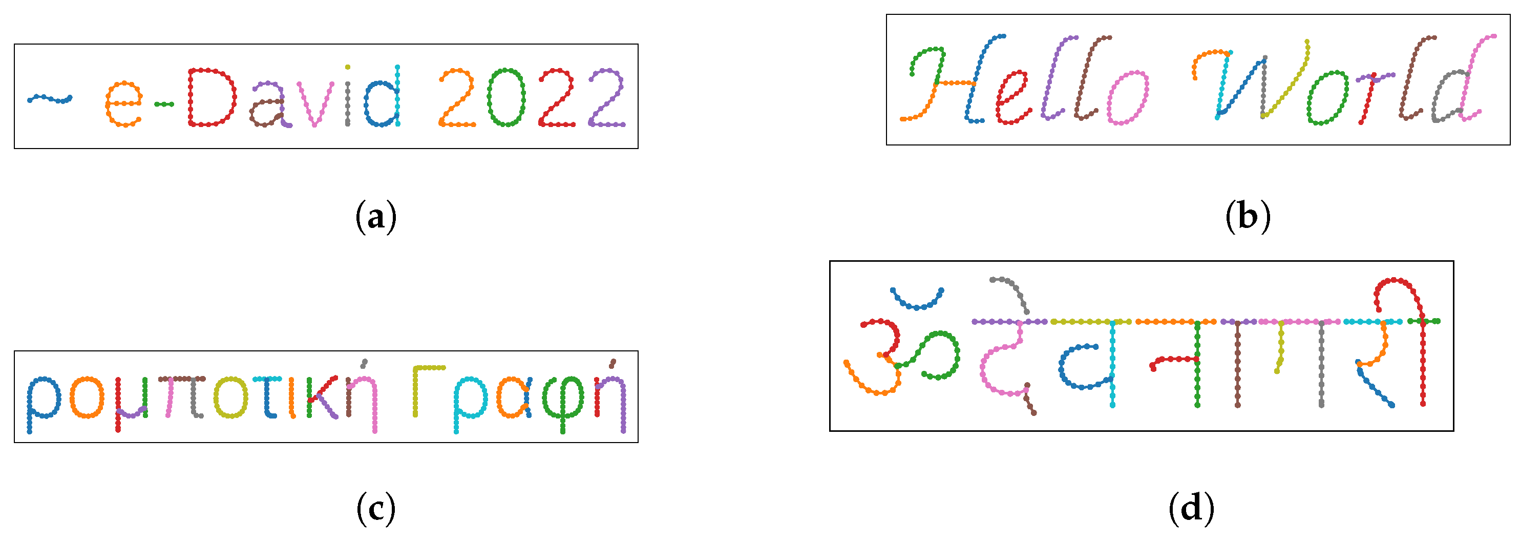
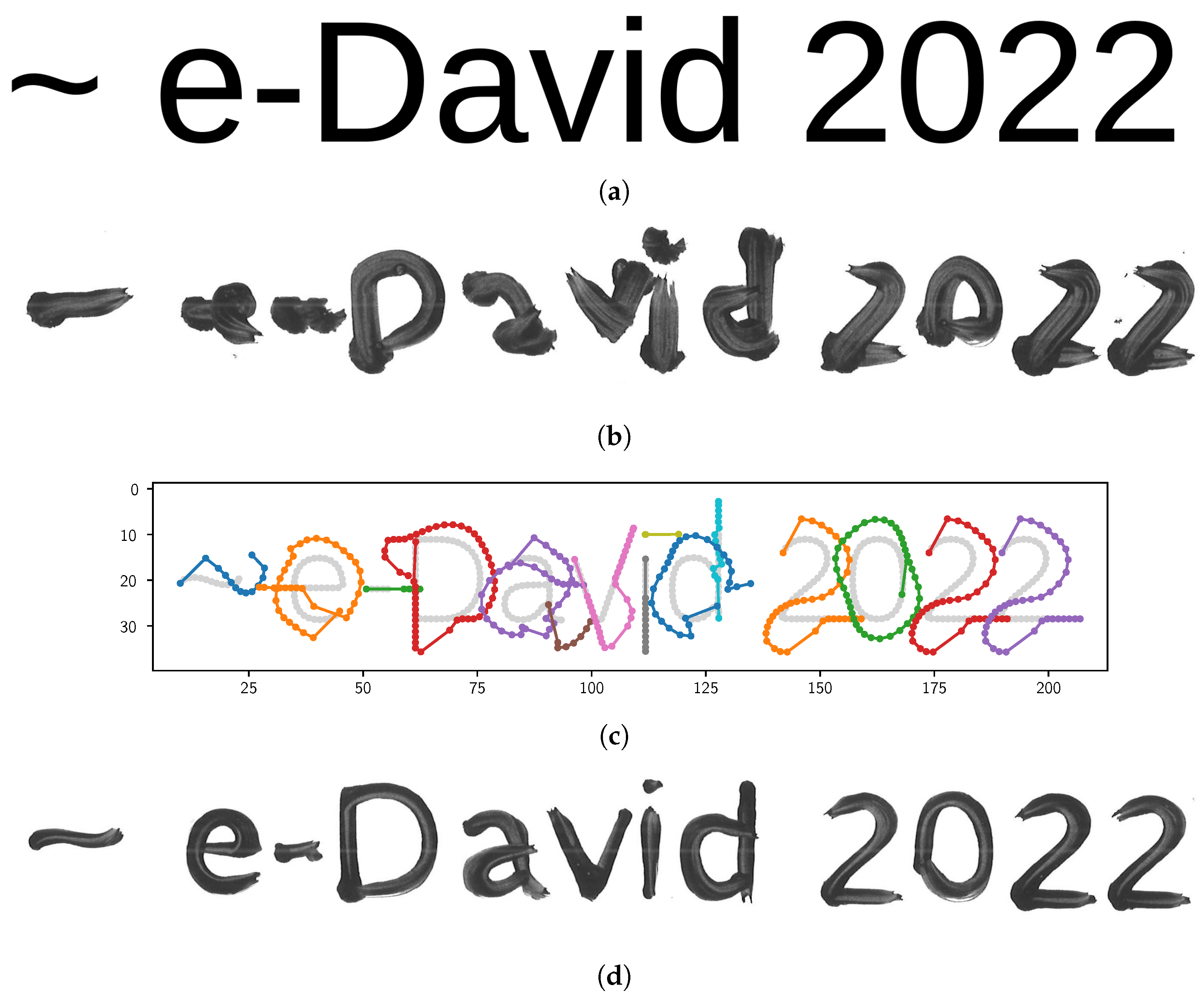
Given a trajectory t, the robotic arm approaches its first control point t 1 by first moving above the point and then lowering the brush straight down until the target pressure of q z , i is reached. For brushes, this generally results in a big blob of color on the canvas as the bristles spread outwards on contact with the canvas. The resulting footprint width is thus greater than predicted using the regression model. To counteract this phenomenon we limit the pressure that can be applied at the beginning of the stroke. From our regression model, we compute the pressure p z e r o such that the brush tip barely touches the canvas, resulting in a stroke of zero width. We set the first points pressure q z , 0 = p z e r o . For further points, we limit the allowed pressure to at most increase linearly with the trajectory length up to that point. Let d i be the trajectory length up to the point t i on the trajectory, such that d 0 = 0 and d i = d i 1 + ( q x , i q x , i 1 ) 2 + ( q y , i q y , i 1 ) 2 . We limit the brush pressure in the following way,
q z , i = min ( q z , i , p z e r o + a d i )
where q z , i are the new pressures for the trajectory t and a is a constant approach slope factor.
For the final realization on the canvas, no visual feedback is used and the computed trajectories are applied directly. Writing brushstrokes need to be placed correctly on the first attempt, since overpainting is not correctable in most cases. However, for evaluation purposes the writing results are recorded by the feedback system.

4. Results

Our method for extracting strokes from glyphs of outline fonts is mostly able to extract strokes similar to strokes that humans would choose. Extracted strokes are of maximum length while having minimum overall curvature. Virtually every typeface can be used as a basis for stroke extraction as long as glyph outlines are provided. In Figure 12, we show extraction results for different texts and typefaces. Avoiding strokes whose parts have high curvature does not always give the best results, as shown in Figure 12b for the letter “H”. Additionally, our method does not correctly extract strokes in places where a glyph suggests the presence of a loop but the glyph outlines do not actually form a loop. Our method is limited to extracting strokes from a single glyphs outline. Many scripts, such as Devanagari, however, contain strokes that extend over multiple letters (Figure 12d) and strokes that should be drawn as a single one are split up erroneously.
Our method for generating brush trajectories from strokes, as described in Section 3.3, generates trajectories that account for brush lag and pressure-dependent stroke width. The text written using our trajectory generation method greatly improves the legibility of the written text. The results of applying our model to the trajectories is shown in Figure 13c.
The target text “∼e-David 2022” is shown in Figure 13a. If drawn without a model, the resulting footprint varies vastly, as shown in Figure 13b. The footprint is distorted because the brush lag is not taken into account. Applying our model to the brush strokes results in the trajectories shown in Figure 13c Using these trajectories, the robot is able to improve the legibility, as shown in Figure 13d. In particular, in regions of high curvature, the effect of brush lag is reduced drastically. The width of the resulting footprint matches the target text more closely.
Further results are shown in Figure 14. Simply assuming a constant brush lag distance independent of the strokes to be drawn improves the legibility already. However, in areas of high curvature the lag is underestimated. Approaching the canvas straight down at the beginning of a stroke will result in blobs (Figure 14b). Using our approach slope method reduces the size of the blobs at the downside of underestimating the required pressure in some cases (Figure 13d and Figure 14c).
Our methods also result in legible written text in non-Latin scripts, such as Japanese, Devanagari, and even imaginary scripts, as long as a corresponding font with outline information is provided (Figure 15). While the text is legible, our generated trajectories do not always accurately match the desired result. In areas of high curvature, our brush model overestimates the required pressure resulting in a stroke of greater width than wanted. At points of high curvature it also underestimates the brush lag, resulting in strokes that are too far on the inside of the target stroke.
While the resulting texts are legible and match the styles of the fonts used, the resulting footprints on the canvas do not perfectly match the actual input. In Figure 16, we show that the written results mostly match the desired. Sometimes, however, our model still overestimates the pressure required to achieve the wanted stroke width or underestimates the brush lag in curves with a very high curvature.

5. Future Work

While our method can write legible text in various typefaces, several limitations exist.
Since we skeletonize outlines and then remove unwanted branches at stroke ends, as described in [9], we require a normalization threshold, which has to be chosen for each font. While Latin scripts tend to have sharp corners at stroke ends and, thus, require greater thresholds to remove them, many Chinese, Japanese, and Korean (CJK) glyphs have rounded or hooked stroke ends and require smaller thresholds. Otherwise, important geometric information is lost. An interesting research direction would be to develop a method to find matching thresholds for a given typeface automatically which minimizes removed information but still removes all spurious branches.
Furthermore, the glyph skeleton exhibits dents at points of intersection, which we fixed by determining intersection groups and merging all nodes of the intersection into a single node, using a constant distance for merging. In particular, in CJK fonts, there are separate stroke intersections close to each other, leading to intersections close to each other being merged mistakenly. In the future, we would like to implement an adaptive method for this problem, similar to the one described in [25].
In our proposed brush model, the only variables are brush pressure, brush lag, stroke width, and stroke curvature. During testing, we observed multiple other variables affecting the brush behavior, such as stroke width changing over the distance of a stroke, while pressure is constant. Furthermore, for now we only considered holding the brush vertically, while most writing is performed with brushes being held at an angle. In the future we could add an overall angle, or lead angle in the direction of the stroke to more closely mimic human brush use. This will necessitate the extension of the calibration pattern to also include multiple angles.
Another parameter to be calibrated is stroke lengthening when lifting the brush at the end of a stroke. As the brush is lifted upwards at the end of the stroke, the friction between the bristles and the canvas decreases and the bristles move forward further than predicted, resulting in a footprint of greater length than desired.
An overall limitation of our method is that accurate reproduction of text is often impossible as there are too many unknown variables affecting the results. For example, after drawing a stroke in one direction, the bristles do not exactly return to their default position but are slightly bent opposite to the drawing direction at the end of the drawn stroke. These long-term deformations results in inaccuracies when drawing the next stroke. This effect has also been measured in [2] and could be remedied by resetting the brush with an external tool before another stroke is placed.
We have also avoided measuring and quantifying the accuracy of our writing results. A simple pixel-based analysis of measuring the overlap of the result with the target font is not very satisfactory, as lots of overpainting takes place and some offsets to the template persist (Figure 16). However, the results are still subjectively legible. In any kind of writing, letters can be varied significantly while still being legible, which is what enables artforms or makes handwritings distinguishable but also unique. A simple comparison to the target text is not ideal in this case. We intend to include legibility metrics, which have been studied in the fields of vision and ergonomics, among others [26,27]. This would also allow us to measure the success of our brush path optimization and allow an iterative process for automatic writing practice.
Despite these current issues, there are also further applications to look into. We chose writing as a first application for our curvature calibration method, however the technique can be applied to many other topics. Since e-David is a painting robot, we also intend to include the calibration data in the painting process. In order to realize precise features in paintings a prediction of brush lag can be useful. Despite the use of visual feedback, some details cannot be corrected once they have been misplaced, which necessitates the ability to place such features accurately without any iteration. Especially if a painting contains known geometric shapes, curved features, such as ellipses or curved parts of polygons, our method is applicable to optimize their realization.

6. Conclusions

The goal of our work was to be able to write arbitrary text in an arbitrary typeface given as an outline font. For this purpose we have implemented a pipeline consisting of stroke extraction, trajectory generation, and final realization. Additionally, we have shown a method to predict brush lag, allowing us to correct brush paths to be more similar to the intended reference glyph. We have shown this approach to work with multiple writing systems, producing results that do contain imperfections but are generally legible. Since individual pipeline components can be easily replaced, other stroke extraction methods can be used with our brush model to generate writing trajectories. Similarly, our method for extracting strokes can be used in combination with other brush models. Our brush model can also be applied in other, non-writing-related fields, such as painterly rendering, to produce more accurate strokes.

Author Contributions

Conceptualization, D.S.Z. and J.M.G.; methodology, D.S.Z.; software, D.S.Z. and J.M.G.; formal analysis, D.S.Z.; investigation, D.S.Z.; resources, O.D.; data curation, D.S.Z.; writing—original draft preparation, D.S.Z.; writing—review and editing, D.S.Z., J.M.G. and O.D.; visualization, D.S.Z.; supervision, J.M.G. and O.D.; project administration, J.M.G. and O.D. All authors have read and agreed to the published version of the manuscript.

Funding

This research received no external funding.

Data Availability Statement

Data sharing not applicable: The data used in this paper is not relevant for distribution, since it characterizes a specific set of brushes. For reuse, the method has to be reimplemented as described and applied on other robotic painting setups. However upon request we gladly make our specific data (measurement results, machine parameters and brush type) available.

Conflicts of Interest

The authors declare no conflict of interest.

References

  1. Lloyd-Davies, V. Sumi-e Painting; Walter Foster Publishing: Mission Viejo, CA, USA, 2019. [Google Scholar]
  2. Gülzow, J.M.; Paetzold, P.; Deussen, O. Recent Developments Regarding Painting Robots for Research in Automatic Painting, Artificial Creativity, and Machine Learning. Appl. Sci. 2020, 10, 3396. [Google Scholar] [CrossRef]
  3. Gülzow, J.M.; Grayver, L.; Deussen, O. Self-Improving Robotic Brushstroke Replication. Arts 2018, 7, 84. [Google Scholar] [CrossRef]
  4. Sun, Y.; Xu, Y. A calligraphy robot—Callibot: Design, analysis and applications. In Proceedings of the 2013 IEEE International Conference on Robotics and Biomimetics (ROBIO), Shenzhen, China, 12–14 December 2013; pp. 185–190. [Google Scholar] [CrossRef]
  5. Deussen, O.; Lindemeier, T.; Pirk, S.; Tautzenberger, M. Feedback-guided stroke placement for a painting machine. In Proceedings of the Eighth Annual Symposium on Computational Aesthetics in Graphics, Visualization, and Imaging, Aire-la-Ville, Switzerland, 4–6 June 2012; pp. 25–33. [Google Scholar] [CrossRef]
  6. Gülzow, J.M.; Deussen, O. Region-Based Approaches in Robotic Painting. Arts 2022, 11, 77. [Google Scholar] [CrossRef]
  7. Wright, T. History and technology of computer fonts. IEEE Ann. Hist. Comput. 1998, 20, 30–34. [Google Scholar] [CrossRef]
  8. Knuth, D.E. METAFONT: A System for Alphabet Design; Technical Report; Stanford University Ca Department of Computer Science: Stanford, CA, USA, 1979. [Google Scholar]
  9. Ogniewicz, R.L.; Ilg, M. Voronoi skeletons: Theory and applications. In Proceedings of the CVPR (Computer Vision and Pattern Recognition Conference), Champaign, IL, USA, 15–18 June 1992; Volume 92, pp. 63–69. [Google Scholar]
  10. Potkonjak, V. Robotic handwriting. Int. J. Humanoid Robot. 2005, 2, 105–124. [Google Scholar] [CrossRef]
  11. Lin, H.I.; Chen, X.; Lin, T.T. Calligraphy Brush Trajectory Control of by a Robotic Arm. Appl. Sci. 2020, 10, 8694. [Google Scholar] [CrossRef]
  12. Wu, R.; Zhou, C.; Chao, F.; Yang, L.; Lin, C.M.; Shang, C. GANCCRobot: Generative adversarial nets based chinese calligraphy robot. Inf. Sci. 2020, 516, 474–490. [Google Scholar] [CrossRef]
  13. Lin, G.; Guo, Z.; Chao, F.; Yang, L.; Chang, X.; Lin, C.M.; Zhou, C.; Vijayakumar, V.; Shang, C. Automatic stroke generation for style-oriented robotic Chinese calligraphy. Future Gener. Comput. Syst. 2021, 119, 20–30. [Google Scholar] [CrossRef]
  14. Mueller, S.; Huebel, N.; Waibel, M.; D’Andrea, R. Robotic calligraphy—Learning how to write single strokes of Chinese and Japanese characters. In Proceedings of the 2013 IEEE/RSJ International Conference on Intelligent Robots and Systems, Tokyo, Japan, 3–7 November 2013; pp. 1734–1739. [Google Scholar] [CrossRef]
  15. Wong, H.T.; Ip, H.H. Virtual brush: A model-based synthesis of Chinese calligraphy. Comput. Graph. 2000, 24, 99–113. [Google Scholar] [CrossRef]
  16. Xu, S.; Tang, M.; Lau, F.; Pan, Y. A solid model based virtual hairy brush. Comput. Graph. Forum 2002, 21, 299–308. [Google Scholar] [CrossRef]
  17. Xu, S.; Tang, M.; Lau, F.C.; Pan, Y. Virtual hairy brush for painterly rendering. Graph. Model. 2004, 66, 263–302. [Google Scholar] [CrossRef]
  18. Berio, D.; Calinon, S.; Leymarie, F.F. Learning dynamic graffiti strokes with a compliant robot. In Proceedings of the 2016 IEEE/RSJ International Conference on Intelligent Robots and Systems (IROS), Daejeon, Republic of Korea, 9–14 October 2016; pp. 3981–3986. [Google Scholar] [CrossRef]
  19. Scalera, L.; Seriani, S.; Gasparetto, A.; Gallina, P. Non-photorealistic rendering techniques for artistic robotic painting. Robotics 2019, 8, 10. [Google Scholar] [CrossRef]
  20. Beltramello, A.; Scalera, L.; Seriani, S.; Gallina, P. Artistic robotic painting using the palette knife technique. Robotics 2020, 9, 15. [Google Scholar] [CrossRef]
  21. Karimov, A.; Kopets, E.; Leonov, S.; Scalera, L.; Butusov, D. A Robot for Artistic Painting in Authentic Colors. J. Intell. Robot. Syst. 2023, 107, 34. [Google Scholar] [CrossRef]
  22. Igno-Rosario, O.; Hernandez-Aguilar, C.; Cruz-Orea, A.; Dominguez-Pacheco, A. Interactive system for painting artworks by regions using a robot. Robot. Auton. Syst. 2019, 121, 103263. [Google Scholar] [CrossRef]
  23. Fan, K.; Li, J.; Li, S. Fine grained control of robotic calligraphy. In Proceedings of the 2018 33rd Youth Academic Annual Conference of Chinese Association of Automation (YAC), Nanjing, China, 18–20 May 2018; pp. 1089–1093. [Google Scholar] [CrossRef]
  24. Zhang, T.Y.; Suen, C.Y. A fast parallel algorithm for thinning digital patterns. Commun. ACM 1984, 27, 236–239. [Google Scholar] [CrossRef]
  25. Favreau, J.D.; Lafarge, F.; Bousseau, A. Fidelity vs. Simplicity: A Global Approach to Line Drawing Vectorization. ACM Trans. Graph. 2016, 35, 1–10. [Google Scholar] [CrossRef]
  26. Arditi, A.; Cho, J. Serifs and font legibility. Vis. Res. 2005, 45, 2926–2933. [Google Scholar] [CrossRef] [PubMed]
  27. Garvey, P.M.; Zineddin, A.Z.; Pietrucha, M.T. Letter legibility for signs and other large format applications. In Proceedings of the Human Factors and Ergonomics Society Annual Meeting (October 2001); SAGE Publications: Los Angeles, CA, USA, 2001; Volume 45, pp. 1443–1447. [Google Scholar]
Figure 1. One of the e-David painting robots.
Robotics 12 00072 g001
Figure 2. Overall pipeline of our method. Textual input and a typeface are converted to brush trajectories that can be executed by the robot by applying a sequence of transformations.
Robotics 12 00072 g002
Figure 3. Process of computing the Voronoi medial axis (VMA) of the character “a” from the Liberation Sans typeface. (a) Glyph outline contour-defining control points. (b) Voronoi diagram of the sampled glyph outline. (c) Sampled outline and corresponding skeleton graph.
Robotics 12 00072 g003
Figure 4. Problematic intersection resulting in more than one intersection in the VMA for the glyph of the Japanese character “ぬ” (nu). (a) Problematic intersection. (b) Fixed intersection.
Robotics 12 00072 g004
Figure 5. Strokes extracted from the Voronoi medial axis. Separate strokes are colored in differently. (a) Character “a” in the Liberation Sans typeface. (b) Character “W” in the Z003 typeface. (c) Character “湊” (harbor) in the IPA Mincho typeface. (d) Character “草” (grass) in the IPA Mincho typeface.
Robotics 12 00072 g005
Figure 6. Semicircle trajectories and resulting footprints. Measured in millimetres. (a) Trajectory for semicircle of 15 mm radius. (b) Canvas of multiple semicircles of differing radii and constant pressure. (c) Trajectory and resulting footprint for semicircle of 15 mm radius and 2.5 mm pressure.
Robotics 12 00072 g006
Figure 7. Process of image binarization. Axes given in pixels of the feedback image. (a) Local Otsu thresholds. (b) Binarized canvas image. (c) Single binarized stroke.
Robotics 12 00072 g007
Figure 8. Extraction of stroke information from brush footprints. Axes given in pixels in the feedback image. Measurements converted to millimetres. (a) A stroke and its skeleton line. (b) Kissing circle at midpoint v m . (c) Stroke width at midpoint v m . (d) Brush lag at midpoint v m .
Robotics 12 00072 g008
Figure 9. Resulting stroke footprint information for a DaVinci College 4 painting brush. (a) Applied pressure and measured curve radius affecting resulting footprint width. (b) Applied pressure and measured curve radius affecting lag distance of the brush.
Robotics 12 00072 g009
Figure 10. Pairwise relationship between brush pressure, curve radius, resulting stroke width and measured brush lag. Measured data points in blue, fitted linear regression in red. (a) Pressure vs. width. (b) Pressure vs. lag. (c) Radius vs. width. (d) Radius vs. lag.
Robotics 12 00072 g010
Figure 11. Regression models predicting required brush pressure and lag distance for a stroke of given curvature and width. (a) Brush pressure prediction. (b) Brush lag prediction.
Robotics 12 00072 g011
Figure 12. Extracted strokes from different strings and typefaces. (a) “∼e-David 2022” in the Liberation Sans typeface. (b) “Hello World” in the Z003 typeface. (c) “ρ ο μ π ο τ ι κ γ ρ α ϕ” (Greek for robotic writing) in the Liberation Sans typeface. (d) “Devanagari” in the Devanagari typeface.
Robotics 12 00072 g012
Figure 13. Improvement due to the application of our stroke model. (a) Original text “∼e-David 2022” rendered in the Liberation Sans typeface. (b) “∼e-David 2022” written with a Da Vinci College 4 brush in the Liberation Sans typeface without brush model and constant 2 mm brush pressure. (c) Trajectories generated by our model for “∼e-David 2022” in the Liberation Sans typeface. Axes given in millimetres. (d) Full brush model. Stroke approach slope 0.5 .
Robotics 12 00072 g013
Figure 14. The text “∼e-David 2022” written with different parameters. (a) Constant brush lag. Stroke with approach slope 0.5 . (b) Full brush model. No stroke approach slope. (c) Full brush model. Stroke approach slope 1.0 .
Robotics 12 00072 g014
Figure 15. Results of writing in non-Latin scripts. (a) “湊あくあ” (“Minato Aqua”, a Japanese name) target text in the IPAMincho typeface. (b) “湊あくあ” written using our method. (c) “Devanagari” (name of an Indian writing system) target text in the Devanagari typeface. (d) “Devanagari” written using our method. (e) Text in the Ancient Hylian typeface. (f) Text written using our method.
Robotics 12 00072 g015
Figure 16. Dissimilarities between the target results and our written results. Correctly colored regions (black), erroneously colored (orange) and uncolored (blue) regions are shown. (a) Liberation Sans. (b) Ancient Hylian, a fantasy script.
Robotics 12 00072 g016
Disclaimer/Publisher’s Note: The statements, opinions and data contained in all publications are solely those of the individual author(s) and contributor(s) and not of MDPI and/or the editor(s). MDPI and/or the editor(s) disclaim responsibility for any injury to people or property resulting from any ideas, methods, instructions or products referred to in the content.

