Abstract
Flexible manipulator systems in specific applications such as space exploration, nuclear waste treatment, medical applications, etc., often have characteristics superior to conventional rigid manipulator systems. However, their elasticity and complex dynamics lead to difficulties encountered in control processes. Research on improving the structure of the control model plays a very important role in reducing the above limitations and achieving great benefits for the flexible manipulator system. In this study, a general method for modelling a flexible robotic manipulator is introduced. Furthermore, two control models for flexible manipulators are proposed. The first model uses two proportional–integral–derivative (PID) controllers, where the first one is used for position control, and the other is applied for vibration reduction. The second model is an enhanced development of the first with the addition of a fuzzy logic controller to optimise oscillation suppression. Selected experimental results are presented and compared to evaluate the performance of the proposed control mechanisms.
1. Introduction
Conventional rigid manipulator systems are designed with a focus on accuracy and stability when performing continuous operations in an automation system. A typical rigid manipulator usually has high stiffness, considerable weight, and size, and its main components are made of hard and heavy materials. To support its operation, a heavy base and a large power actuator are required, which add to the overall weight and size of the system. Furthermore, this also leads to higher energy consumption and increases operating, maintenance, and transportation costs.
As a solution to the problems mentioned above, an alternative to rigid manipulators is flexible manipulator systems (FMS). These systems are designed using lightweight and resilient materials, which makes them much lighter and smaller than conventional manipulators. Moreover, FMSs can operate using smaller actuators with significantly lower energy consumption. These systems also allow for increased manoeuvrability and ease of transportation. In general, flexible manipulator systems require lower costs while providing higher performance in applications requiring lightweight and more complex movements.
The main characteristics of the FMSs are their lightweight and resilient construction that result in complex vibrations on the movement components (especially the joints and links) [1,2]. This is a big challenge for controlling the system. If a full solution to this problem is achieved, FMSs will demonstrate their true potential in replacing conventional rigid manipulator systems for specific applications. The flexibility in robotic manipulators is basically created by the mechanical structures of links and joints. The link flexibility is due to the reduction of its weight in order to decrease inertial forces and achieve faster manipulation speed. The joint flexibility is achieved due to the elasticity of gearboxes and shafts. The model of a flexible manipulator typically consists of two parts, namely, the model for flexible links and the model for elastic joints.
The vibration of flexible manipulators has infinite resonance modes. This means that models of manipulators are also described by infinite dimensions of mathematical equations. However, high-order elements of vibration have very small amplitudes. As a result, the original dynamic equations can be truncated to achieve a finite-dimensional model by utilising either the assumed modes method (AMM) or the finite element method (FEM) [3].
A number of model formulations have been published previously, but they are deficient in various ways. For instance, Moallem et al. outlined an AMM model based on input-output linearisation [4]. However, this approach was complex because a Hurwitz matrix was achieved by solving a pole placement problem. De Queiroz et al. presented a flexible link robot manipulator by combining distributed parameter field equations and finite-dimensional equations [5]. However, some important system parameters were not mentioned in the model, such as the rotary inertia of the hub and the rotary inertia of the mass of the link’s free end [6]. Cheong et al. showed a two-flexible-link manipulator model under a clamped-mass boundary condition and argued that there was a change in mode shapes in the links due to nonlinear couplings [7]. In this case, the authors did not consider the elasticity of the joints of the arms.
There are also many works on developing flexible manipulator models utilising the FEM approach [8,9,10,11,12]. This research employs the assumed modes method to build a model with link flexibility and joint elasticity because of the following reasons. First, the number of differential equations of motion in the AMM case is fewer than that in the FEM [13], so the AMM method requires less computational time. Second, flexible manipulators have uniform cross-sectional geometries; therefore, it is easier to apply the AMM method. Furthermore, the FEM method encounters difficulty in treating the coupling of degrees of freedom (DOF) between links [6]. Third, in the case where experimental hardware is not available, the AMM is more suitable for research based on numerical simulations. This is because the time-dependent frequency equations of the AMM have been solved perfectly.
Various studies on FMS control methods have been proposed with many different control techniques. Most of these studies are done with experimental models or simulation environments to evaluate control algorithms and collect system characteristics. Studies often approach FMS control techniques with structures ranging from 1-DOF to 3-DOF. These studies focus mainly on single-link systems [14]. The elastic deformation of these systems is observed along a horizontal or vertical plane. These systems are controlled with actuators located at the joints or the location where the flexible link is attached to the joints. However, the effectiveness of the method is still unclear.
Other studies used only PID, PD, or PI controllers with different models. Zhou et al. established a two-link flexible manipulator system made of a piezoelectric smart structure. The manipulator’s motion was controlled by a single-chip computer system, and the data exchange between the manipulator system and the MATLAB workspace was implemented by an acquisition module that combined the physical system with a virtual environment. This study used the PID control algorithm to effectively suppress the vibration of a flexible manipulator [15]. However, the oscillating nature of the arm still persists, with a rather long oscillation damping time. Another work presented an investigation into the development of open-loop and closed-loop control strategies for flexible manipulator systems [16]. This research proposed closed-loop control strategies using both collocated (hub angle and hub velocity) and non-collocated (end-point acceleration) feedback. In these strategies, a collocated proportional and derivative (PD) control is developed, and its performance is studied through experimentation. However, the hardware architecture still needs to be adjusted for a better response.
Some works use fuzzy logic controllers or combine fuzzy logic controllers with PID controllers to improve the control quality of flexible manipulator arms. Dehghani and Khodadadi focused on improving the tracking performance of flexible joint robot (FJR) manipulators. In the first step, the physical relations of the system are used to determine a model for the FJR. A fuzzy logic self-tuning PID (FLST-PID) controller is introduced to keep the rotating angle of the link of the FJR at the desired position. In this controller, the parameter values are computed by intelligent methods like fuzzy logic, and they vary during the controlling process [17]. However, the controller structure still needs to be improved in the direction of directly using the output properties to control the system. Another work uses a fuzzy logic controller to adjust the manipulator’s velocity and position [18]. The performance of these control techniques is sufficient to reduce vibrations; however, this vibration control approach only considers the variation of the rotation angle at the joint and does not take into account the oscillation at the end of the arm.
In addition to the above control techniques, several studies used other methods to reduce vibration in the flexible arm. Geniele et al. focused on the tip-position control of a single flexible link that rotates in the horizontal plane [19]. In this research, an output feedback control strategy using the principle of transmission zero assignment is used to achieve tracking for this time-invariant system. The control approach consists of two parts. The first part is an inner (stabilising) control loop that incorporates a feedthrough term to assign the system’s transmission zeros to desired locations in the complex plane. The second part is a feedback servo loop that allows tracking of the desired trajectory. However, the control system still uses simple feedback output and has not yet resolved the nature of the oscillation. Zhang et al. proposed a PD (proportion differentiation) controller based on NNs (neural networks) in order to achieve accurate trajectory tracking of the flexible arm and improve the speed of position tracking [20]. In this research, the dynamic model of a single-link flexible manipulator is established based on the lumped method and the assumed mode method. The optimisation of PD parameters is achieved by NNs to increase the robustness and adaptability of the overall system. However, the study only gives simulation results. On the other hand, the model of the flexible arm is relatively complicated and needs experimental results to be verified. Another work presented a hybrid control scheme for vibration and tip deflection control of a single-link flexible manipulator system [21]. The control structure consists of a resonant controller and a fuzzy logic controller (FLC). The resonant controller is applied as the inner loop feedback controller for vibration control using the resonant frequencies at different resonant modes of the system. The fuzzy logic controller is implemented as the outer loop feedback controller for the tracking control and to achieve zero steady-state errors. However, the study did not specify the nature of the oscillations and only gave simulation results.
Recently, Li et al. used Hamilton’s principle to derive the partial differential equation (PDE) dynamic model of a flexible manipulator [22]. In this research, a boundary control approach is proposed, and the Nussbaum function is adopted in the controller design to circumvent the problem of unknown control directions. However, the paper has not yet clearly shown the relationship between the oscillating nature and the efficiency of the controller. Moreover, the experimental model has not been introduced to verify the research results. Another research proposes a control method combining the RBF (Radial Basis Function) neural network and pole placement strategy to suppress the rotation angle fluctuations [23]. The function of the RBF neural network is to identify uncertain items caused by the manipulator’s flexibility and the time-varying characteristics of dynamic parameters. In this work, the pole placement strategy is introduced to optimise the PD (Proportional Differential) controller’s parameters to improve the response speed and stability. However, under the influence of gravity, the oscillation of the flexible manipulator can be quickly self-damped, and the model testing needs further consideration of its practical applicability. Meng et al. deal with an uncertain two-link rigid-flexible manipulator with vibration amplitude constraints, intending to achieve its position control via motion planning and an adaptive tracking approach [24]. The motion trajectories for the two links of the manipulator are planned based on virtual damping and online trajectory correction techniques. In this work, an adaptive tracking controller is designed using the radial basis function neural network and the sliding mode control technique under uncertainties, including unmodeled dynamics, parameter perturbations, and persistent external disturbances acting on the joint motors. However, the study has only given simulation results and has not given a direction to determine the controller parameters corresponding to the model parameters.
The above-mentioned works mainly use traditional composite materials. In addition, there are many studies on using smart materials, such as piezoelectric materials for actuators as well as sensors. Malgaca and Uyar investigated a hybrid vibration control of a smart composite box manipulator (SCBM) using passive control (PC) and active control (AC) techniques [25]. The PC is achieved with a trapezoidal velocity profile, while for AC, the PID control with displacement and strain feedback is applied to the SCBM, which is driven with the cases in the PC for further reducing residual vibrations. Another work proposed the couple optimal placement criterion of piezoelectric actuators on the basis of the modal H2 norm [26]. A composite controller is also designed for the active vibration control of the piezoelectric smart, single flexible manipulator. Recently, an article presented the hysteresis modelling and precision trajectory control of a piezoelectric micromanipulator with actuator saturation [27]. In this work, the system model is decomposed into linear reversible parts and bounded parts, and the H∞ feedback controller is used to ensure system stability and accuracy. It can be seen that smart materials promise many applications. However, there are issues that need more attention in the approach related to piezoelectric materials, such as complex fabrication technology, hysteresis of control signals and feedback, and system implementation costs.
For the research on elastic joints, there have been many articles mentioned with different approaches. Szabat and Orlowska-Kowalskar carried out an analysis of control structures for the electrical drive system with elastic joints [28]. In this research, the synthesis of the control structure with a proportional–integral controller supported by different additional feedbacks was presented, and the classical pole-placement method was applied. For low resonance frequencies, Brock et al. introduced a motion control system with a multi-mass mechanism consisting of a filter damping higher resonance frequencies and an adaptive speed controller [29]. In recent years, many works have also continued to produce research results on control systems with two-mass and multi-mass systems [30,31] and the two-mass system with backlash [32,33]. Another work proposed a control algorithm using regulators and input shaping for a two-mass system [34]. The algorithm allows switching between input shaping and fuzzy control. However, it can be seen that these might be harmful to the mechanical and electrical parts of the system and could have an impact on high-frequency oscillation excitation.
For an effective solution, the main focus of this paper is to propose a general method for flexible arm modelling and a hybrid control technique for using PID controllers and fuzzy logic. The techniques implemented in this study are a model that uses a PID controller as a compensator to rapidly reduce oscillations and an enhanced fuzzy logic controller to significantly improve the control goal.
The article is divided into the following sections. Section 2 introduces a general method for the mathematical modelling of a flexible arm. A new control approach using PID and fuzzy logic is presented in Section 3. Section 4 details the hardware structure and experimental performance properties of the control methods.
2. Mathematical Modelling
This section focuses on introducing a flexible manipulator modelling method for a multi-link and multi-joint robotic arm case. Figure 1 shows the structure of a manipulator with multiple flexible links and elastic joints. It comprises nL flexible links and nJ elastic joints. The links are connected in series and rotated by motors with flexible shafts. The end tip of the distal link is connected to a payload with mass Mp and inertia Ip. The elastic joints are simplified as torsional springs linking the rotors with inertia Iri and the hubs of flexible links with inertia Ihi (Figure 2), i denotes the index of links and joints. Rotor and link angles are denoted by αi and θi, respectively. Gri and ksi are transfer ratios of gearboxes and constant coefficients of the springs. Link parameters consist of lengths li, masses mi, and uniform flexural rigidities EIi.
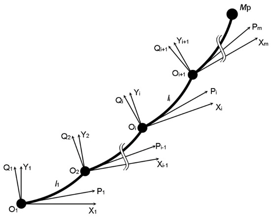
Figure 1.
Generalised structure of multi-flexible link manipulators.
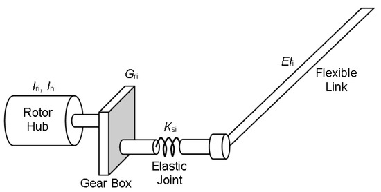
Figure 2.
Generalised structure of multi-flexible link manipulators.
The model makes the following assumptions:
- The links are assumed to move in a horizontal plane, and the effect of gravity is ignored.
- The payload attached to the last link is considered a concentrated mass.
- The longitudinal deflections of the links are negligibly small.
- The arm is considered to be uniform.
According to Denavit and Hartenberg [35], links are assigned to the inertial coordinate frames OXiYi and the moving coordinate frames OPiQi (Figure 3). The deflection of the free end of the ith link at the distance ξ and time t is vi(ξ i,t) as expressed below [36]:
where φij(ξi) is a mode shape function; qij(t) is a time-varying modal function; i is the link index; and j is the mode number; n is the number of modes.
where
and
where ωij is the natural frequency of the ith link and jth shape mode, and ρi is the mass per unit length of the ith link [37].
where Aij, Bij are coefficients.
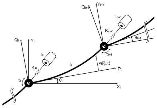
Figure 3.
The ith link of the flexible manipulator.
The dynamic equations of the system are derived from the total kinetic energy and total potential energy of the arms. The kinetic energy of the whole arm can be expressed as
K = Kl + Kh + Kr + Kp,
The kinetic energy due to the motion of the hubs is given by
with Ihi being the inertia of the hubs. The energy created when the links move can be written as
According to Figure 3, σi(θi, ξi, t) are the vectors of ξ I on coordinate OiXiYi and can be expressed as [39]
Substituting for from (12) in (10) yields
Similarly, the energy due to the motion of the payload can be calculated from (13) with ξi = li,
where Mp is the mass of the payload.
The total potential energy is expressed by
P = Plinks + Pjoints,
In addition, when the system moves, a part of the total energy D is consumed by friction from the bearings and the contact of links with the environment:
with
where Kmi = diag(kij), and kij (j = 1…n) are damping coefficients.
The dynamic model is obtained by substituting the above energy expressions (from (6) to (18)) in Lagrange’s equation [36]:
where V is the Lagrangian variable
V = K − P.
L is the vector of variables in the system:
and F is the vector of applied control signals:
Next, (19) can be expressed as
where J is the modified rotor inertia matrix, MAA, MAB, and MBB are the mass matrices, Km is the damping coefficient matrix, KS is the spring coefficient matrix, and gA and gB are the vectors containing terms due to the interaction of the link angles and the modal displacements.
The stiffness matrix due to the link flexibility is presented as
Kt = diag(kt1, kt2, …, ktn),
Equation (23) can be written in shortened form as:
This can be rewritten in state space form:
where
3. Control Structure
3.1. Filter-Based Damping Control Scheme
Based on the above mathematical model, depending on the structure of the arm, the control signal F is applied to the joints. The research in this paper considers the flexible link and rigid joint cases. The control of the flexible robotic arm is achieved through two basic loops. The first loop is used to control the angular position of the rotating motor (Figure 4). The second loop is used to control oscillations, usually at the end of the arm. To achieve a fast and accurate angular position factor, the first loop is made through the PID controller. For the second loop, initially, this study uses a PID controller with an improved oscillator feedback stage. Then, the control structure is improved with a fuzzy inference engine to optimise the control signal and ensure efficient control at the oscillation damping stages.
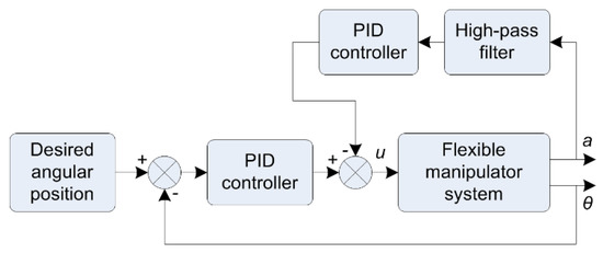
Figure 4.
Control scheme with filter-based controller.
For the first approach, two output signals are used as feedback for each control loop, namely the angular position θ at the joint for the position control loop and the linear acceleration a at the end of the arm for the oscillating control loop. The control signal u to the actuator in the system is generated by combining the control signals from the PID controllers in both control loops. The upper loop PID controller contributes to the overall control signal as a compensator to reduce vibration.
The problem with flexible manipulator control is that it necessitates minimising oscillation at the free end by actuating the torque of the motor. Obviously, this is a way of far indirect control. In actual operations, the free oscillating position is not precisely determined. This is due to the difficulty of effectively placing a position sensor in real operations. Instead, a sensor located at the head of the free oscillation is used to measure the acceleration of the oscillation. This sensor provides the nature, state, and shape of the oscillation at the terminal.
The motion at the end of the flexible link is a combination of soft motion and rigid motion. The rigid motion is the non-oscillation component generated by the position controller. The soft motion is formed by the kinematics of the flexible arm, which is considered a combination of many rigid finite elements. The oscillator controller needs information about the soft motion. This information is extracted using a fast first-order high-pass filter to achieve a minimum delay time. This is the feedback signal in the collocated loop. The filter transfer function is simplified as follows:
with the passband gain of −T2/T1 and the cutoff frequency being calculated with
Figure 5 (bottom) shows the oscillation characteristics of the manipulator’s end effector in the case of using only the position controller. It can be seen that the oscillation is at a high level and lasts for a long time. To reduce oscillation, the significance of the control in this study is to bring this feedback, or the oscillation property of the arm end, to zero.
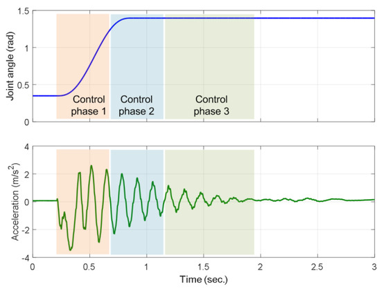
Figure 5.
Division of control parts depending on control error and oscillation level.
3.2. Hybrid Damping Control Scheme
In control practice, the oscillating component discussed above is a feedback signal. The gain factor of this feedback characteristic has a great impact on the overall performance of the system. In this study, the vibration-damping process is divided into three stages (Figure 5, top). The first stage is the vibration formation process. At this stage, the variation of soft motion is quite large, and the control signal needs to act at a large level to reduce the formation of oscillations. The second stage is the steady oscillation phase when the rigid movement has reached the desired position. At this stage, the active signal needs to stay lower to avoid generating new oscillations. The third stage is the phase of descending oscillation. At this stage, the oscillator function needs to gradually reduce its feedback nature and bring the arm end to stability.
Through the evaluation, it can be seen that the PID controller itself is difficult to control the oscillations in the above three characteristic stages. This study proposes a new development with the use of a fuzzy logic inference model to identify the phases and change the impact properties of the oscillator controller. The structure of this improved model is depicted in Figure 6. This approach is called the advanced fuzzy-PID model (AF-PID).
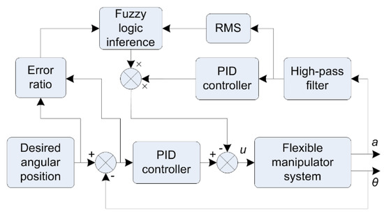
Figure 6.
Hybrid control scheme with the combination of PID and fuzzy logic.
The fuzzy controller should have the function of determining the stages of the damping process. The first stage can be determined from the moment the set signal begins to change until the angular position of the motor reaches the set value. This information can be determined from the position controller error signal. Thus, the position error is an input to the fuzzy controller.
The duration of the second-stage oscillation depends on the dynamic properties of the manipulator system. For the convenience of computation as well as the simplification of the control structure and related programmes, the time of the second stage is assumed to be equal to the time of the first stage. The timing factor determination is done by the control software, and a second-stage timing signal is provided to the fuzzy controller.
The duration of the third stage is often undetermined. The damping factor of the oscillation depends on the efficiency of the first two periods. During this third period, in addition to the time factor, the magnitude of the feedback oscillator will determine the impact on the oscillation, so the input to the fuzzy controller also has the time signal and the average amplitude of the arm’s oscillation signal.
To accomplish the above task, the input to the Mamdani fuzzy controller is obtained from the oscillation level and the control angle deviation from the set value (Figure 6). Each input has five membership functions with a range of normalised values in the range [0, 1]. The output also includes five membership functions with a range of normalised values in the range [0, 1]. The if-then rule is described in Table 1. The abbreviations are the names of the membership functions with the following estimates: VS–very small, RS–relatively small, SS–small, RB–relatively big, and BB–big.

Table 1.
If-then rules of fuzzy logic inference.
The surface of variation between the input and the output according to the if-then rule is depicted in Figure 7.
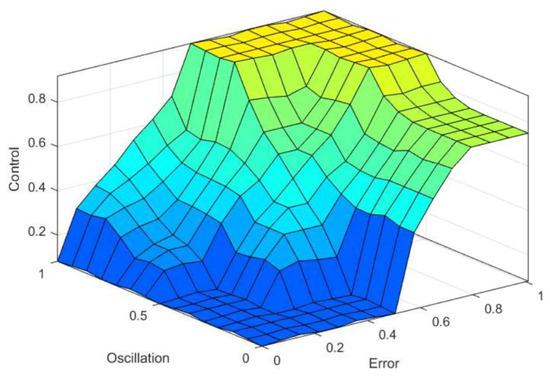
Figure 7.
Fuzzy logic inference with two inputs and one output.
4. Experimental Results
4.1. Hardware Structure
To observe and evaluate the performance of each control scheme, a test bench of the single-link flexible manipulator system is built. Figure 8 shows the components of the manipulator, and Figure 9 is the actual image.
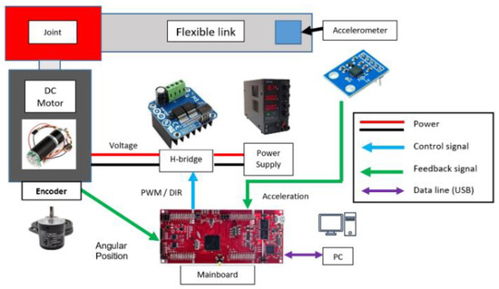
Figure 8.
Hardware components of the flexible manipulator.
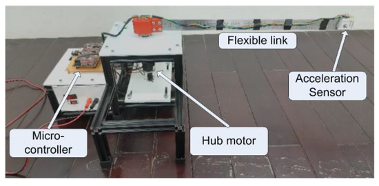
Figure 9.
Actual picture of the flexible manipulator.
The two control approaches described above are supposed to work on the same hardware. The motherboard uses Texas Instruments’ TMS320F28379D microcontroller. The function of this microcontroller is to process the feedback signal from the sensors, generate a control signal based on the corresponding algorithms, and feed this control signal as a combination of PWM (Pulse Width Modulation) and the DIR signal (motor rotation direction) to a MOSFET H-bridge. An analogue accelerometer is used to measure the acceleration at the end of the flexible link and send the accelerometer data to the motherboard. Hence, the data acquisition time is very short, and the delay time is short enough not to affect the accuracy of the algorithm. The flexible link is attached to a rigid joint that rotates on the shaft of a DC-geared motor. This motor is driven from the H-bridge, and its angular position is measured and sent to the motherboard by a revolution encoder attached to the shaft of the motor.
The implementation of the system is performed in MATLAB and Simulink environments using the Embedded Coder Support Package. A personal computer (PC) performs the tasks of transmitting reference angular position input from the interface in Simulink as well as receiving data outputs from the prototype and displaying those on the PC’s monitor for data collection and observation. The acceleration values and graphs collected from this test rig are the primary data for performance verification and assessment of the control models in this research. The primary specifications of the prototype are displayed in Table 2.

Table 2.
Parameters of the flexible manipulator.
4.2. Performance of a Filter-Based Damping Controller
This section analyses the experimental results to evaluate the performance of the two introduced control approaches. The angle of rotation of the manipulator shaft is controlled from 20° to 80° with a Gaussian signal (Figure 5–top) to measure the acceleration at the end of the flexible manipulator system. The cut-off frequency of the required high-pass filter is set to a sufficient frequency value, allowing the lowest first flexible mode to be separated. In this case, the use of a high-pass filter with an 8.0 Hz cut-off frequency would be adequate. The flexible manipulator is set with a structural damping DS = 0.028. The Ziegler-Nichols method is used to obtain the filter-based PID controller parameters. The set of PID controller parameters thus obtained is Kp = 8, KI = 1.2 and Kd = 0.24.
Figure 10 illustrates the performance of the PID model in reducing vibration through acceleration data compared to the case of no vibration control. From the overall observation, there is a significant reduction in the magnitude of the acceleration at the end of the arm. However, the difference in oscillation reduction time in both cases is quite small, and the oscillation persists for a relatively long time. In addition, the oscillation frequency of around 8.2 Hz does not change when performed in the presence of a controller.
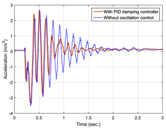
Figure 10.
Performance of filter-based PID damping control.
It can be seen that, during the initial time of motion, when the angle changes to reach the set value, the magnitude of the acceleration in both the uncontrolled and the controlled cases is relatively similar. However, at the second stage of the movement, the vibrational strength decreases significantly by about 62%. In the final part of the oscillation reduction, the vibration measured by the model shows that the oscillation rate decreases more slowly than in the second stage. This may indicate that, in the third stage, the properties or parameters need to be adapted to this stage. The time to steady state of the model is faster than the case without control, but not significantly.
Figure 11 shows the control signal characteristics (dotted red) after implementing the oscillation compensation method according to the PID mechanism. It can be seen that the control signal has an oscillating component that corresponds to the oscillating component of the arm end when the arm moves. When the point of arrival angle is reached, the oscillation signal decays rapidly, and the control signal is thus attenuated. It can also be seen that the oscillation frequency of the control signal has the same value as the terminal frequency of the arm. However, the control value has reversed phase when compared with the corresponding signal in the arm. This performs the function of oscillation suppression at the end of the arm.
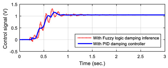
Figure 11.
Control signal of the PID damping scheme.
4.3. Performance of Hybrid Fuzzy Logic-PID Controller
Figure 12 shows the performance of the AF-PID model compared to the case where the oscillation control algorithm is applied by the filter-based controller. The data in the graph shows a rapid decrease in the magnitude of the acceleration. Thanks to the proposed control algorithm, the oscillation reduction time is fast, and the oscillation is suppressed early. In the first stage, the magnitude of the acceleration is greatly reduced (over 80%). In the second stage, the acceleration controlled by the AF-PID approach decreases rapidly compared to the uncontrolled case. In the final stage, the oscillation level is rapidly reduced to zero, and the flexible arm is stabilised.
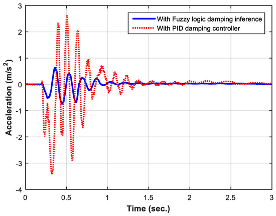
Figure 12.
Comparison of PID damping controller and Fuzzy logic damping inference.
When comparing the system performance between the two control methods, it can be seen that the oscillation characteristics are formed in the first stage, and thanks to the controller, the oscillation is rapidly decreased in the second stage. The characteristic also shows that the oscillation frequency seems to change little when applying the oscillation controller.
For the AF-PID controller, the first-stage oscillation characteristic is significantly minimised, making it easier to handle the second-stage oscillation. This shows that the AF-PID controller has more flexibility in assessing the level of oscillation and providing the appropriate level of feedback to affect the motor where motion is initiated and also where it is only possible to dampen the oscillation of the whole system. Since then, the AF-PID controller task has actually been easier in the second and third stages. Particularly in the third stage, the AF-PID controller shows its superiority over the filter-based controller because it needs a lighter action to suppress the oscillations. This avoids secondary oscillations and ensures faster suppression of oscillations when a pure PID controller is applied. Therefore, it can be seen that the oscillation time of total suppression in the case of using the AF-PID controller is really faster than that of the pure PID controller.
For the control signal, the performance of the control method (Figure 11, solid blue line) is compared with the case of using a filter and PID controller (dotted red line). It can be seen that, at the first stage, the control signal has a larger degree of attenuation to limit the formation of new oscillations. After this period, the amplitude of oscillation is significantly reduced because the oscillation at the end of the arm is clearly suppressed. Hence, when the target control angle point is reached, the oscillations in the motor shaft seem to cancel out in proportion to the oscillations in the arm.
To clearly understand the superiority of the method, it is possible to refer to some previously studied systems with the soft manipulator system having the corresponding resonant frequency, as mentioned in [40]. Through the obtained characteristics, it can be seen that the hybrid method using fuzzy inference has a better frequency response with a significantly faster oscillation damping time. In addition, it is also shown that the high-order oscillator components are also better suppressed.
5. Conclusions
Modelling the flexible arm is a challenge. To be able to control precisely with high efficiency, the model must show the nature of the flexible arm, especially the vibrational characteristics. This study introduced a general model of such a flexible arm that could be applied to different complexity levels. The process of oscillation of the arm in motion has different properties at each stage. Therefore, the controller needs to have appropriate responses for each of these stages. This study proposed and successfully tested a hybrid controller to quickly dampen oscillations depending on different oscillation stages. The hybrid control mechanism is a combination of a PID controller (which is quite effective in motion control) and a fuzzy controller (which is suitable for complex systems). It can be seen that the proposed method is capable of effectively reducing oscillations with a significantly shortened oscillation time thanks to the introduction of the control energy in accordance with the oscillation properties. This result contributes to a more practical application of this kind of manipulator with superiority in saving materials, saving energy, and improving safety.
Author Contributions
Conceptualisation, V.B.N.; methodology, V.B.N.; software, X.C.B.; validation, V.B.N.; formal analysis, V.B.N.; investigation, V.B.N.; resources, V.B.N. and X.C.B.; data curation, V.B.N.; writing—original draft preparation, V.B.N. and X.C.B.; writing—review and editing, V.B.N.; visualisation, V.B.N. and X.C.B.; supervision, V.B.N. All authors have read and agreed to the published version of the manuscript.
Funding
This research is funded by International University, Vietnam National University Ho Chi Minh City (VNU-HCM) under grant number T2022-03-EE/HĐ-ĐHQT-QLKH.
Data Availability Statement
Not applicable.
Acknowledgments
The author(s) wishes to gratefully thank International University, Vietnam National University Ho Chi Minh City (VNU-HCM) for providing the research grant and facilities.
Conflicts of Interest
The authors declare no conflict of interest. The funders had no role in the design of the study; in the collection, analyses, or interpretation of data; in the writing of the manuscript; or in the decision to publish the results.
References
- Aubrun, J.N. Theory of the control structures by low-authority controllers. J. Guid. Control 1980, 3, 444–451. [Google Scholar] [CrossRef]
- Book, W.J.; Alberts, T.E.; Hastings, G.G. Design strategies for high-speed lightweight robots. Comput. Mech. Eng. 1986, 26–33. [Google Scholar]
- Ge, S.S.; Lee, T.H.; Zhu, G. Improving regulation of a single-link flexible manipulator with strain feedback. IEEE Trans. Robot. Autom. 1998, 14, 179–185. [Google Scholar] [CrossRef]
- Moallem, M.; Patel, R.V.; Khorasani, K. An Inverse Dynamics Control Strategy for Tip Position Tracking of Flexible Multi-Link Manipulators. IFAC Proc. Vol. 1996, 29, 85–90. [Google Scholar] [CrossRef]
- De Queiroz, M.S.; Dawson, D.M.; Agarwal, M.; Zhang, F. Adaptive nonlinear boundary control of a flexible link robot arm. IEEE Trans. Robot. Autom. 1999, 15, 779–787. [Google Scholar] [CrossRef]
- Chen, W. Dynamic modeling of multi-link flexible robotic manipulators. Comput. Struct. 2001, 79, 183–195. [Google Scholar] [CrossRef]
- Cheong, J.; Youm, Y.; Chung, W. Joint tracking controller for multi-link flexible robot using disturbance observer and parameter adaptation scheme. J. Robot. Syst. 2002, 19, 401–417. [Google Scholar] [CrossRef]
- Meek, J.L.; Hua, L. Nonlinear dynamics analysis of flexible beams under large overall motions and the flexible manipulator simulation. Comput. Struct. 1995, 56, 1–14. [Google Scholar] [CrossRef]
- Du, H.; Lim, M.K.; Liew, K.M. A nonlinear finite element model for dynamics of flexible manipulators. Mech. Mach. Theory 1996, 31, 1109–1119. [Google Scholar] [CrossRef]
- Ge, S.S.; Lee, T.H.; Zhu, G. A nonlinear feedback controller for a single-link flexible manipulator based on a finite element model. J. Robot. Syst. 1997, 14, 165–178. [Google Scholar] [CrossRef]
- Nagaraj, B.; Nataraju, B.; Ghosal, A. Dynamics of a two-link flexible system undergoing locking: Mathematical modelling and comparison with experiments. J. Sound Vib. 1997, 207, 567–589. [Google Scholar] [CrossRef]
- Gamarra-Rosado, V.; Yuhara, E. Dynamic modeling and simulation of a flexible robotic manipulator. Robotica 1999, 17, 523–528. [Google Scholar] [CrossRef]
- Theodore, R.; Ghosal, A. Comparison of the Assumed Modes and Finite Element Models for Flexible Multilink Manipulators. I. J. Robot. Res. 1995, 14, 91–111. [Google Scholar] [CrossRef]
- Tokhi, M.O.; Azad, A.K.M. Flexible Robot Manipulators Modelling, Simulation and Control, Control Engineering Series, 2nd ed.; The Institution of Engineering and Technology: London, UK, 2017. [Google Scholar]
- Zhou, J.; Li, L.; Ye, L.; Cao, Q. Research on hardware-in-the-loop real-time simulation system for vibration control of Figflexible manipulator. In Proceedings of the IEEE 10th International Conference on Computer-Aided Industrial Design & Conceptual Design, Wenzhou, China, 26–29 November 2009. [Google Scholar] [CrossRef]
- Tokhi, M.O.; Azad, A.K.M. Control of Flexible Manipulator Systems. Proc. Inst. Mech. Eng. Part I J. Syst. Control Eng. 1996, 210, 113–130. [Google Scholar] [CrossRef]
- Dehghani, A.; Khodadadi, H. Fuzzy Logic Self-Tuning PID control for a single-link flexible joint robot manipulator in the presence of uncertainty. In Proceedings of the 15th International Conference on Control, Automation and Systems (ICCAS), Busan, Republic of Korea, 13–16 October 2015. [Google Scholar] [CrossRef]
- Shi, J.; Zheng, W.; Li, J.; Chen, D. A distributed fuzzy logic controller based aptitudinal control for single-link flexible manipulator. In Proceedings of the IEEE Symposium on Electrical & Electronics Engineering (EEESYM), Kuala Lumpur, Malaysia, 24–27 July 2012. [Google Scholar] [CrossRef]
- Geniele, H.; Patel, R.V.; Khorasani, K. Control of a flexible-link manipulator. In Proceedings of the IEEE International Conference on Robotics and Automation, Nagoya, Japan, 21–27 May 1995. [Google Scholar] [CrossRef]
- Zhang, H.; Gao, X.; Xu, G. Research on Improved PD Control of Flexible Manipulator. In Proceedings of the Chinese Control and Decision Conference (CCDC), Nanchang, China, 3–5 June 2019. [Google Scholar] [CrossRef]
- Abdullahi, A.; Mohamed, Z.; Muhammad, M.; Bature, A. Vibration and tip deflection control of a Single-link flexible manipulator. Int. J. Instrum. Control Syst. 2013, 3, 17–27. [Google Scholar] [CrossRef]
- Li, L.; Cao, F.; Liu, J. Vibration control of flexible manipulator with unknown control direction. Int. J. Control 2021, 94, 2690–2702. [Google Scholar] [CrossRef]
- Shang, D.; Li, X.; Yin, M.; Li, F. Control Method of Flexible Manipulator Servo System Based on a Combination of RBF Neural Network and Pole Placement Strategy. Mathematics 2021, 9, 896. [Google Scholar] [CrossRef]
- Meng, Q.; Lai, X.; Yan, Z.; Su, C.Y.; Wu, M. Motion Planning and Adaptive Neural Tracking Control of an Uncertain Two-Link Rigid–Flexible Manipulator with Vibration Amplitude Constraint. IEEE Trans. Neural Netw. Learn. Syst. 2022, 33, 3814–3828. [Google Scholar] [CrossRef]
- Malgaca, L.; Uyar, M. Hybrid vibration control of a flexible composite box cross-sectional manipulator with piezoelectric actuators. Compos. Part B Eng. 2019, 176, 107278. [Google Scholar] [CrossRef]
- Lu, E.; Li, W.; Yang, X.; Wang, Y.; Liu, Y. Optimal placement and active vibration control for piezoelectric smart flexible manipulators using modal H2 norm. J. Intell. Mater. Syst. Struct. 2018, 29, 2333–2343. [Google Scholar] [CrossRef]
- Wu, G.; Yang, Y.; Li, C.; Wei, Y. H Infinity Feedback Control of a Piezoelectric Micromanipulator with Actuator Saturation. In Proceedings of the IEEE International Conference on Manipulation, Manufacturing and Measurement on the Nanoscale (3M-NANO), Tianjin, China, 8–12 August 2022. [Google Scholar] [CrossRef]
- Szabat, K.; Orlowska-Kowalska, T. Vibration Suppression in a Two-Mass Drive System Using PI Speed Controller and Additional Feedbacks—Comparative Study. IEEE Trans. Ind. Electron. 2007, 54, 1193–1206. [Google Scholar] [CrossRef]
- Brock, S.; Luczak, D.; Nowopolski, K.; Pajchrowski, T.; Zawirski, K. Two Approaches to Speed Control for Multi-Mass System with Variable Mechanical Parameters. IEEE Trans. Ind. Electron 2016, 64, 3338–3347. [Google Scholar] [CrossRef]
- Łuczak, D. Nonlinear Identification with Constraints in Frequency Domain of Electric Direct Drive with Multi-Resonant Mechanical Part. Energies 2021, 14, 7190. [Google Scholar] [CrossRef]
- Szabat, K.; Wróbel, K.; Dróżdż, K.; Janiszewski, D.; Pajchrowski, T.; Wójcik, A. A Fuzzy Unscented Kalman Filter in the Adaptive Control System of a Drive System with a Flexible Joint. Energies 2020, 13, 2056. [Google Scholar] [CrossRef]
- Zawirski, K.; Nowopolski, K.; Wicher, B. Experimental Analysis of Selected Control Algorithms of Electromechanical Object with Backlash and Elastic Joint. In Proceedings of the 2016 IEEE International Power Electronics and Motion Control Conference (PEMC), Varna, Bulgaria, 25–28 September 2016; pp. 1161–1166. [Google Scholar]
- Nowopolski, K.; Wicher, B. Parametric Identification of Electrical Drive with Complex Mechanical Structure Utilizing Particle Swarm Optimization Method. In Proceedings of the 2017 19th European Conference on Power Electronics and Applications (EPE’17 ECCE Europe), Warsaw, Poland, 11–14 September 2017; pp. 1–10. [Google Scholar]
- Łuczak, D.; Gniadek, M. Interaction of input shaping and fuzzy logic control. In Proceedings of the 20th International Conference on Methods and Models in Automation and Robotics (MMAR), Miedzyzdroje, Poland, 22–25 August 2015; pp. 886–891. [Google Scholar] [CrossRef]
- Denavit, J.; Hartenberg, R. A kinematic notation for lower-pair mechanisms based on matrices. J. Appl. Mech. 1955, 22, 215–221. [Google Scholar] [CrossRef]
- Meirovitch, L. Analytical Methods in Vibrations; Macmillan: New York, NY, USA, 1967. [Google Scholar]
- Morris, A.; Madani, A. Quadratic optimal control of a two-flexible-link robot manipulator. Robotica 1998, 16, 97–108. [Google Scholar] [CrossRef]
- Subudhi, B.; Morris, A. Singular perturbation approach to trajectory tracking of flexible robot with joint elasticity. Int. J. Syst. Sci. 2003, 34, 167–179. [Google Scholar] [CrossRef]
- Fu, K.S.; Gonzalez, R.C.; Lee, C.S.G. Robotics: Control, Sensing, Vision and Intelligence; McGraw-Hill: New York, NY, USA; London, UK, 1987. [Google Scholar]
- Tokhi, M.O.; Azad, A.K.M. Chapter 9—Collocated and non-collocated control. In Flexible Robot Manipulators Modelling, Simulation and Control, 2nd ed.; The Institution of Engineering and Technology: London, UK, 2017; pp. 261–292. [Google Scholar]
Disclaimer/Publisher’s Note: The statements, opinions and data contained in all publications are solely those of the individual author(s) and contributor(s) and not of MDPI and/or the editor(s). MDPI and/or the editor(s) disclaim responsibility for any injury to people or property resulting from any ideas, methods, instructions or products referred to in the content. |
© 2023 by the authors. Licensee MDPI, Basel, Switzerland. This article is an open access article distributed under the terms and conditions of the Creative Commons Attribution (CC BY) license (https://creativecommons.org/licenses/by/4.0/).