
Multi-Domain Dynamic Modelling of a Low-Cost Upper Limb Rehabilitation Robot


Abstract
:1. Introduction
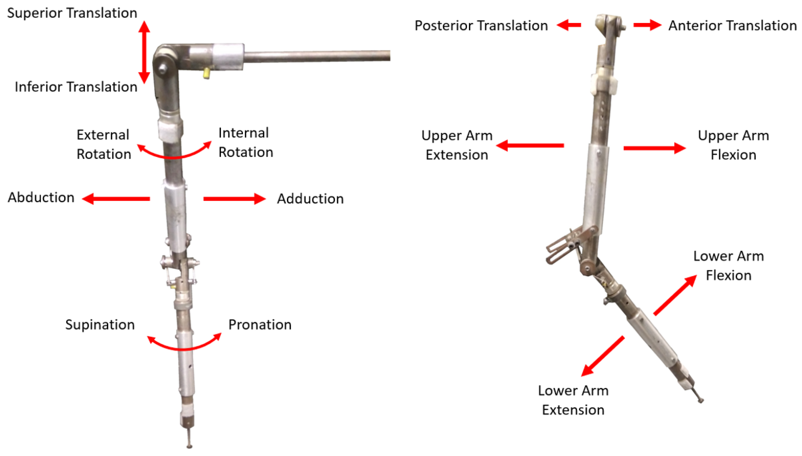
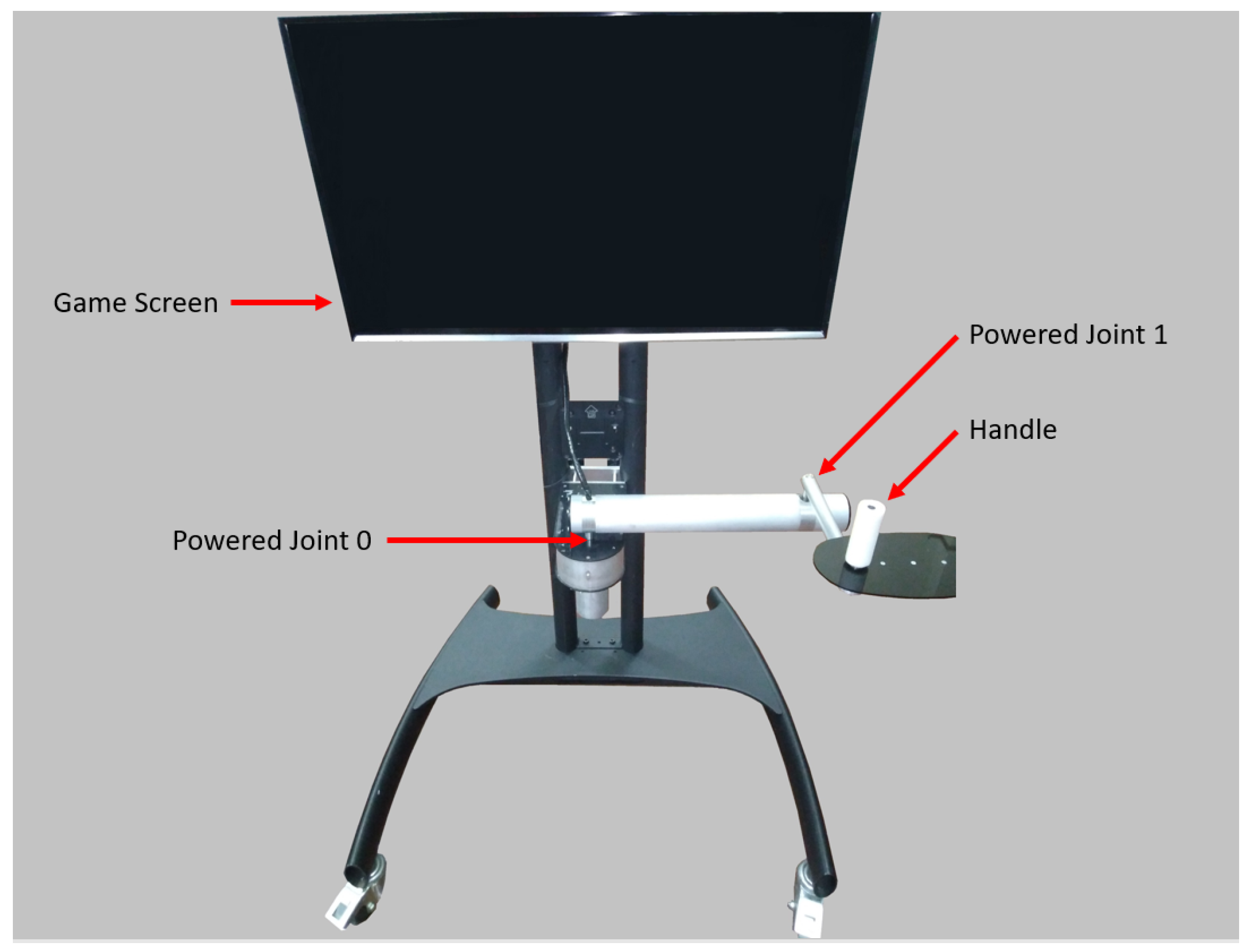
1.1. MyPAM Rehabilitation Robot
1.2. Dynamic Modelling
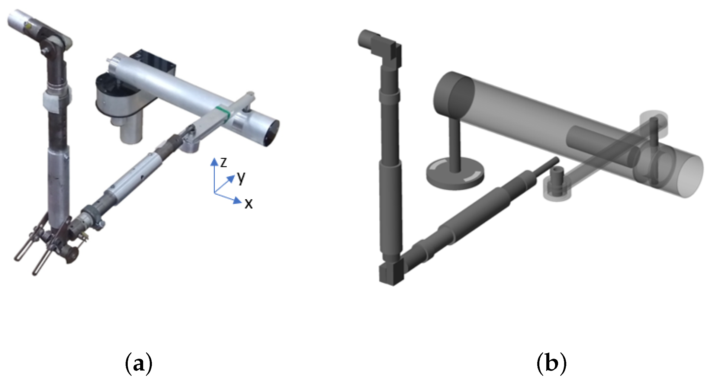
1.3. Human Arm Proxy
1.4. Aim
2. Computational Modelling
2.1. Computational Modelling and Simulation—SimScape Multibody and the Mechanical Domain
- Define the global reference point, coordinate system, and simulation settings by placing the world frame block in parallel with the solver configuration block and the mechanism configuration block;
- In turn, place and configure a solid body block for a component or place and configure a joint;
- Connect the block input/output ports, ensuring that rigid body transforms are used where appropriate to translate or rotate frames.
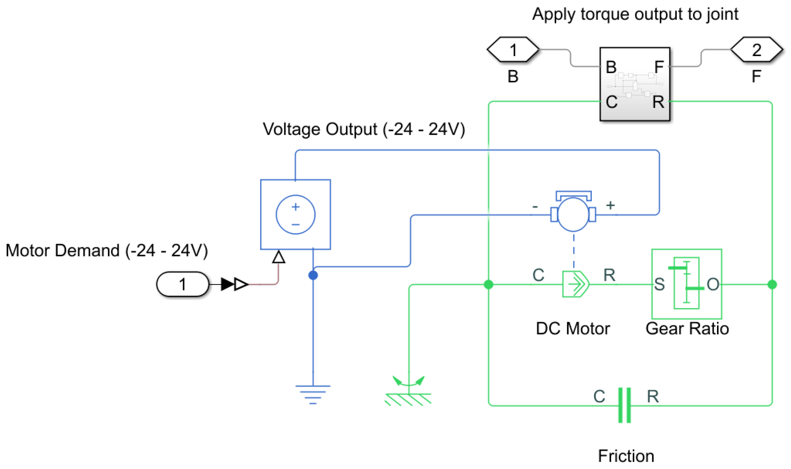
2.2. Computational Modelling and Simulation—SimScape and the Electro-Mechanical Domain
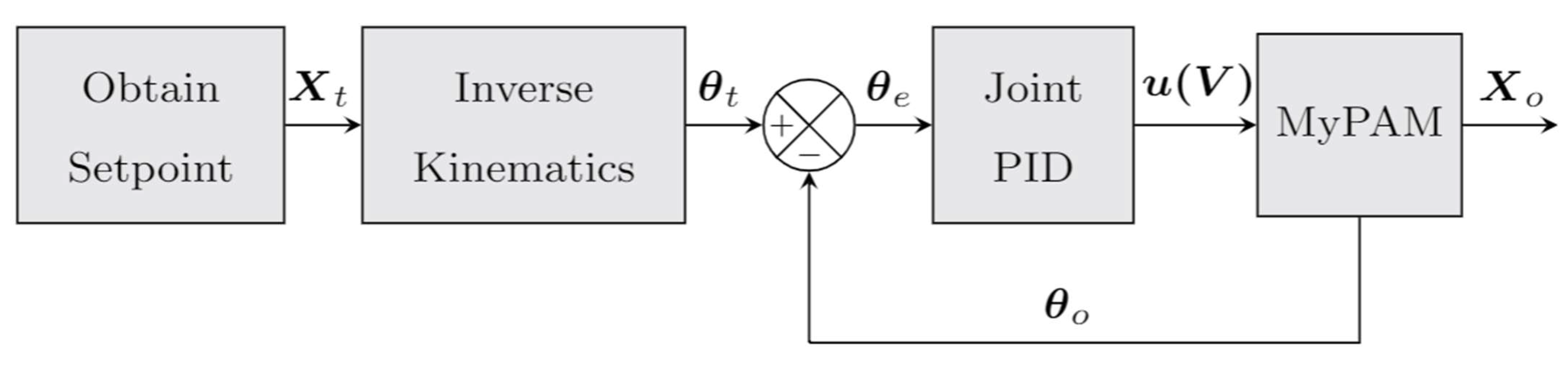
2.3. Computational Modelling and Simulation—MATLAB, Simulink, and the Control Domain
3. Testing and Validation
Methodology
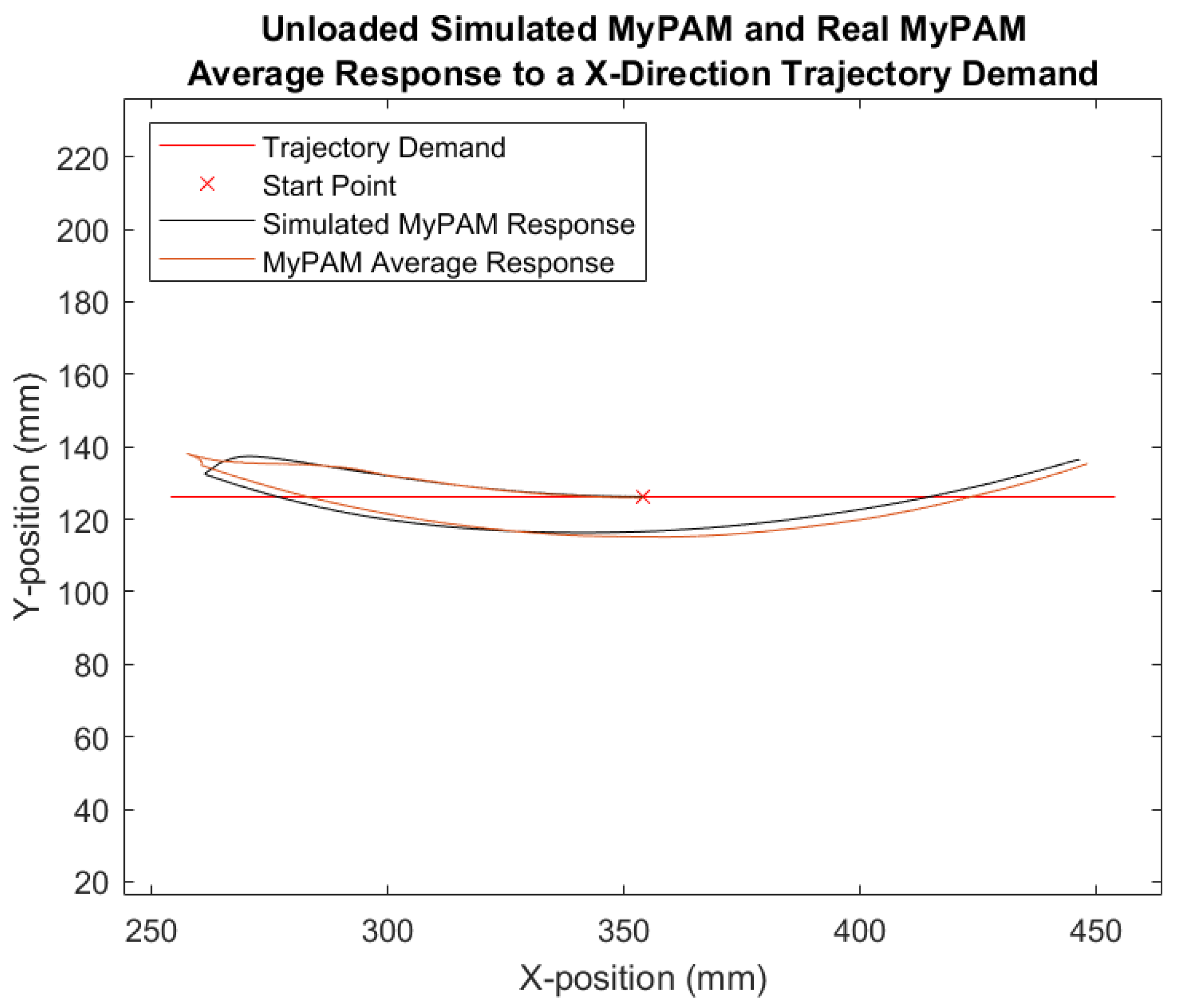
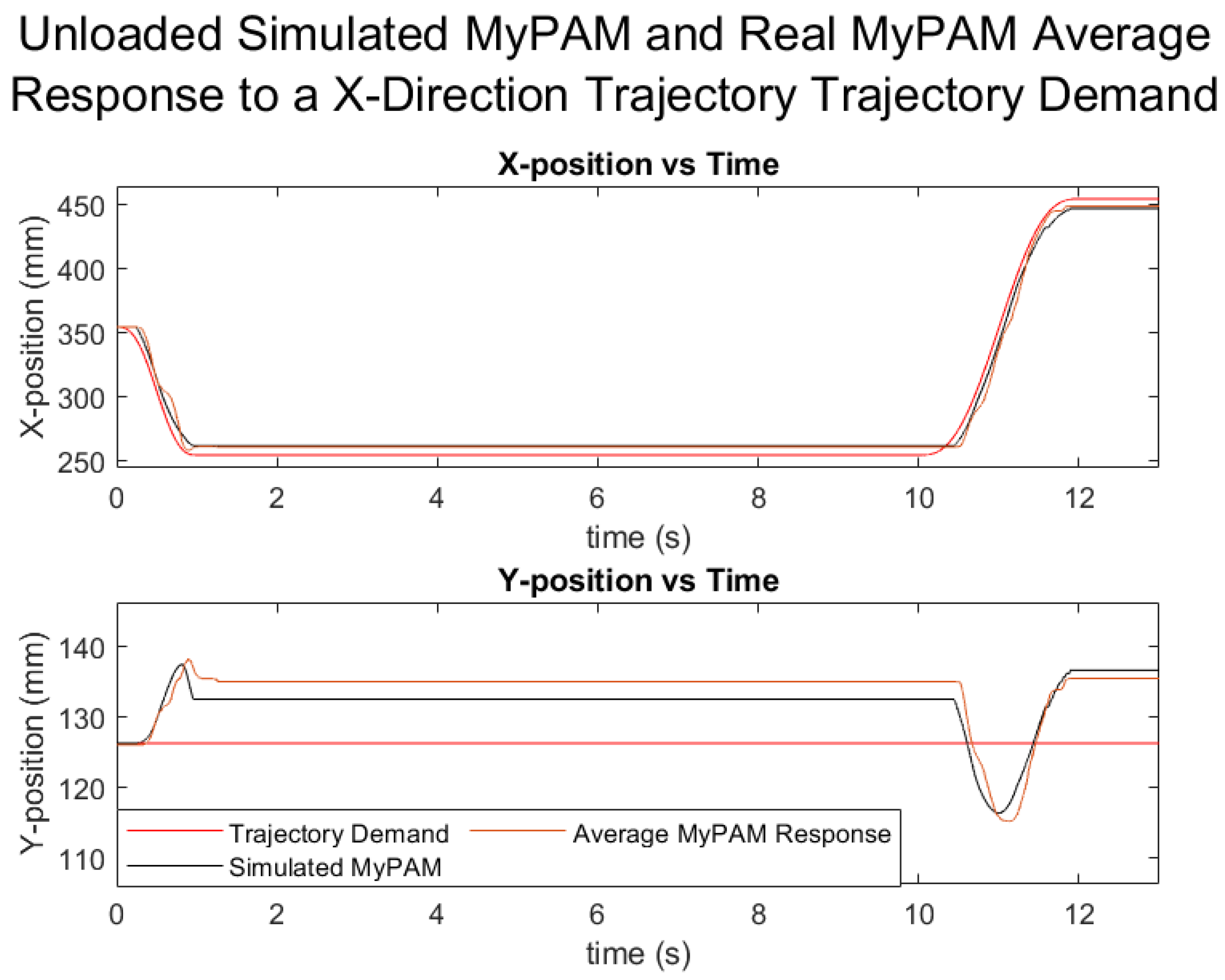
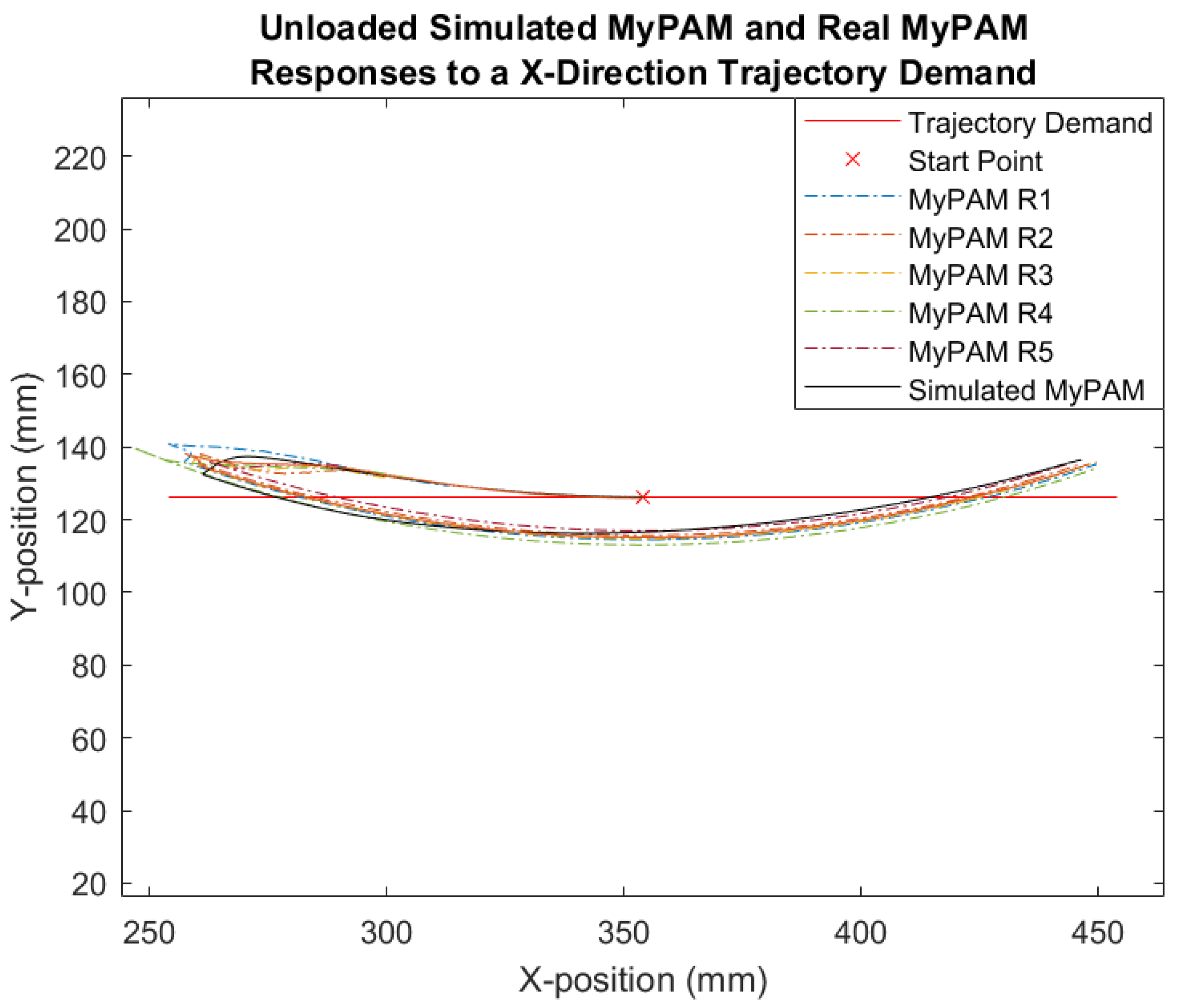
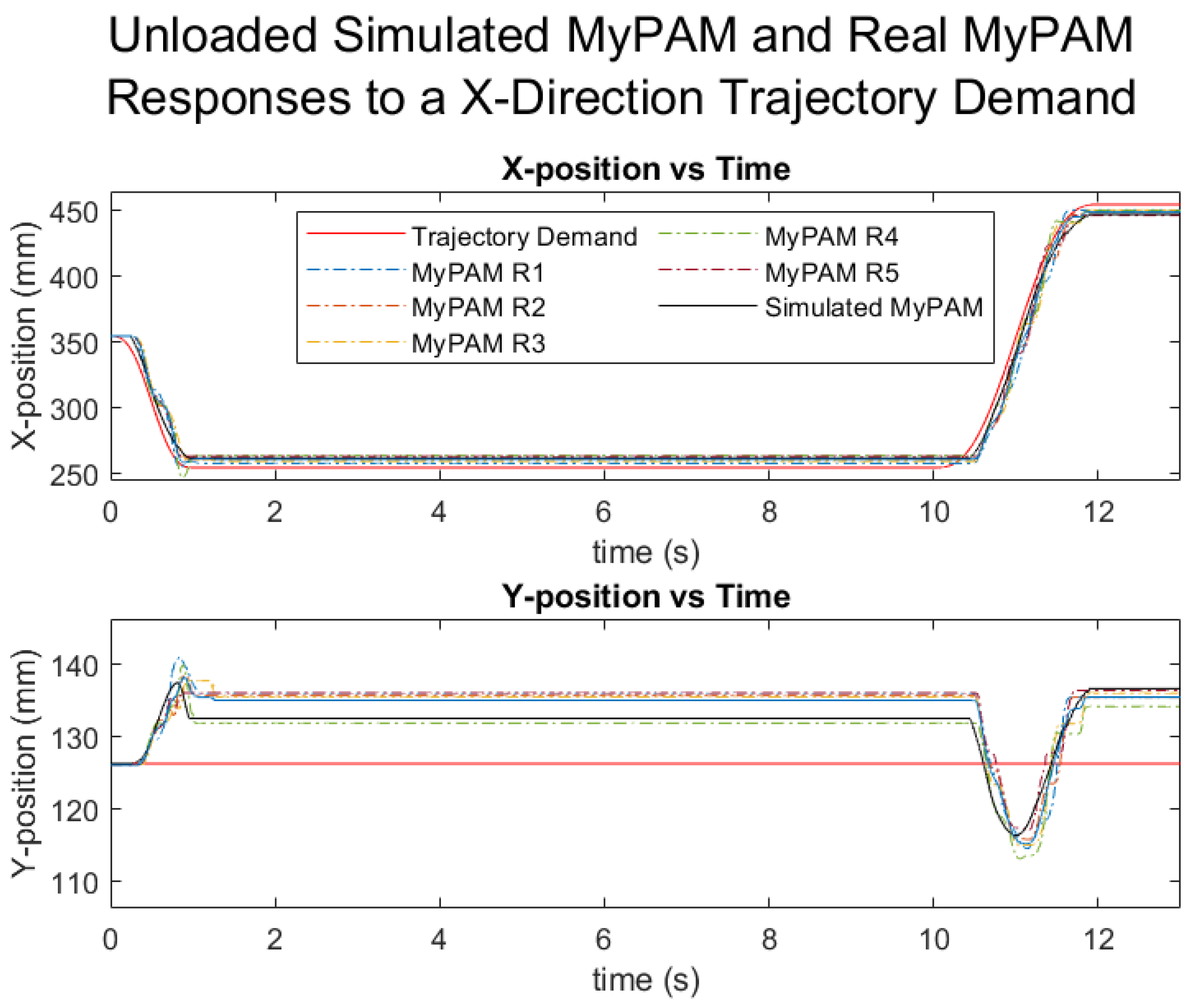
4. Results
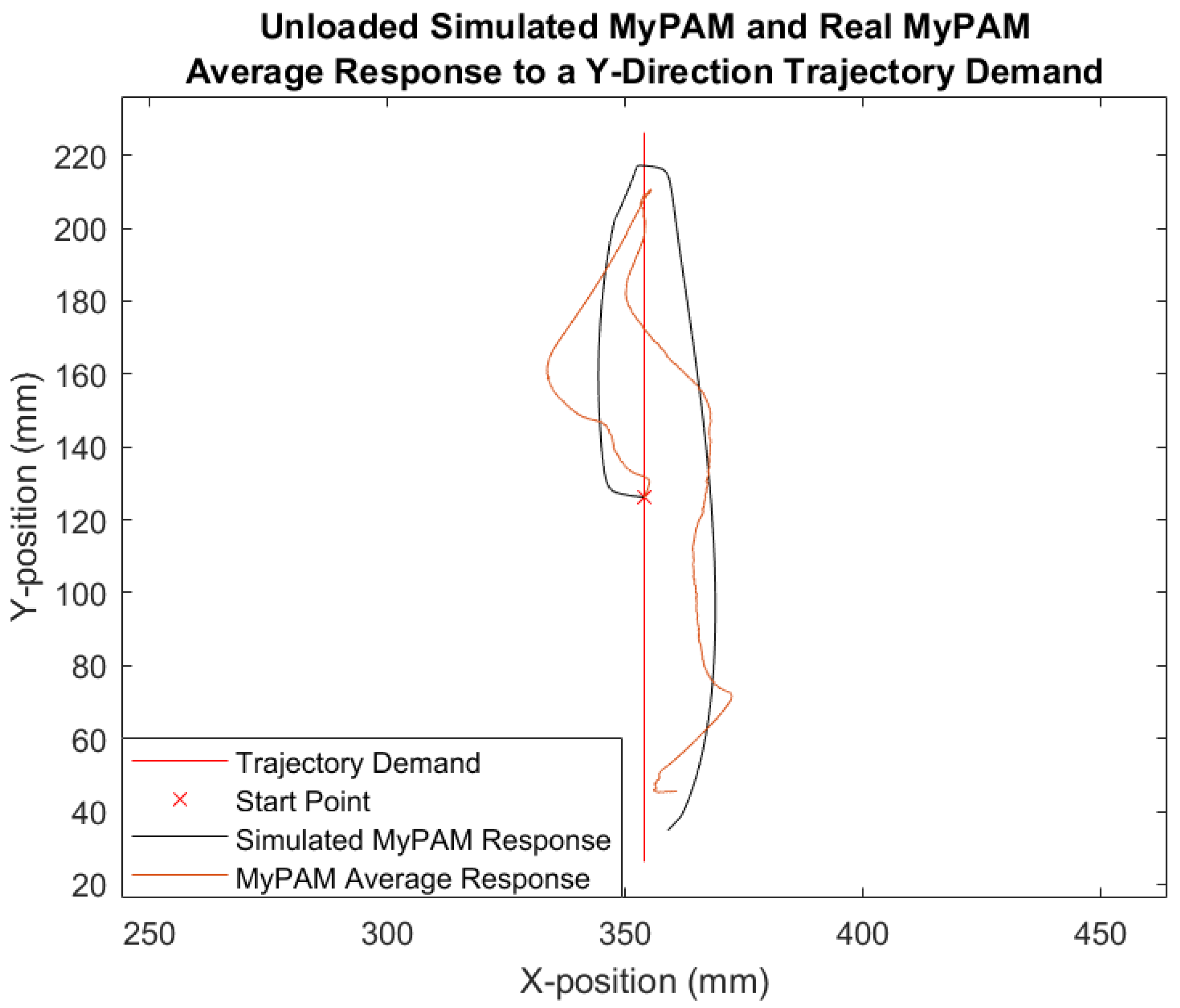
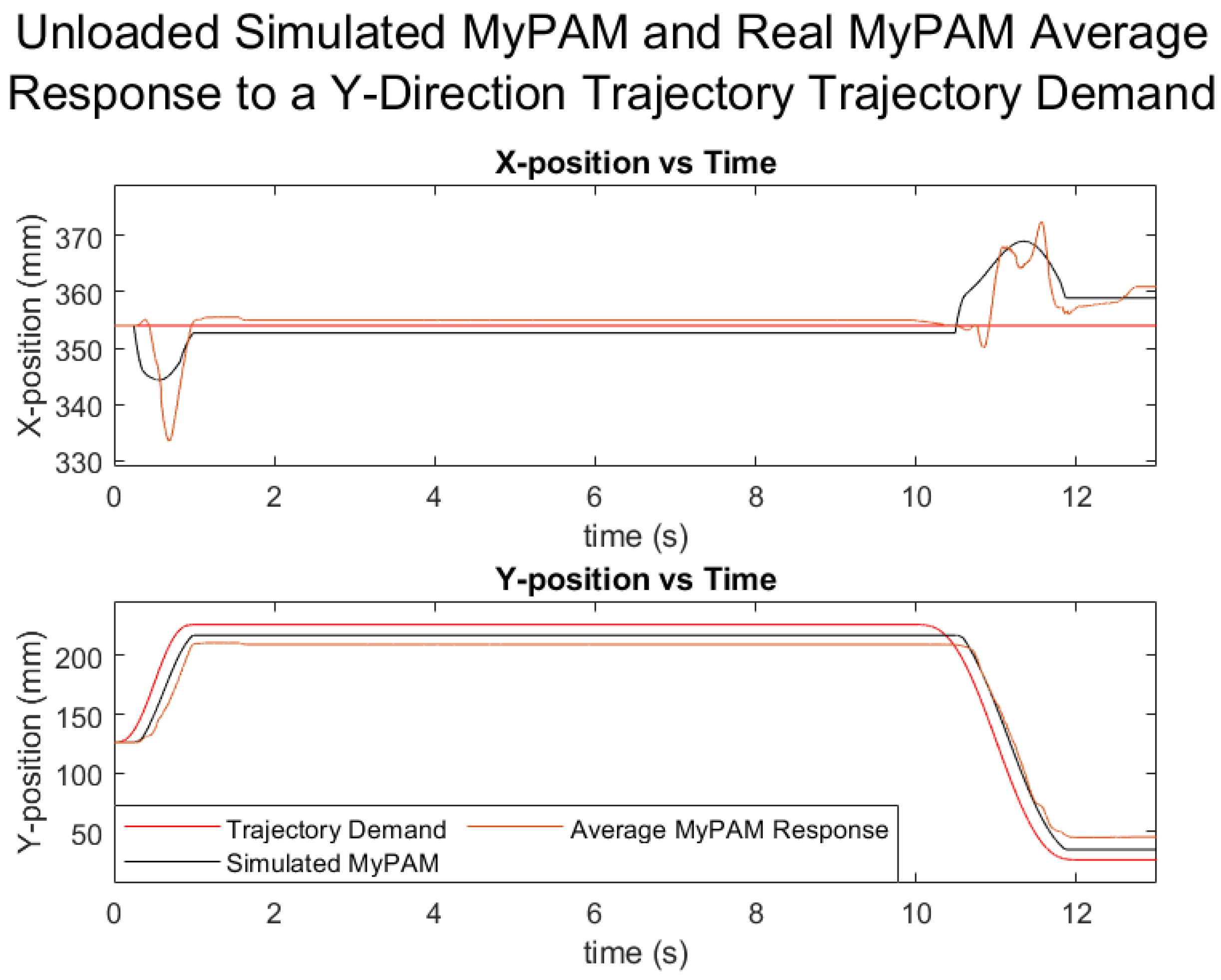
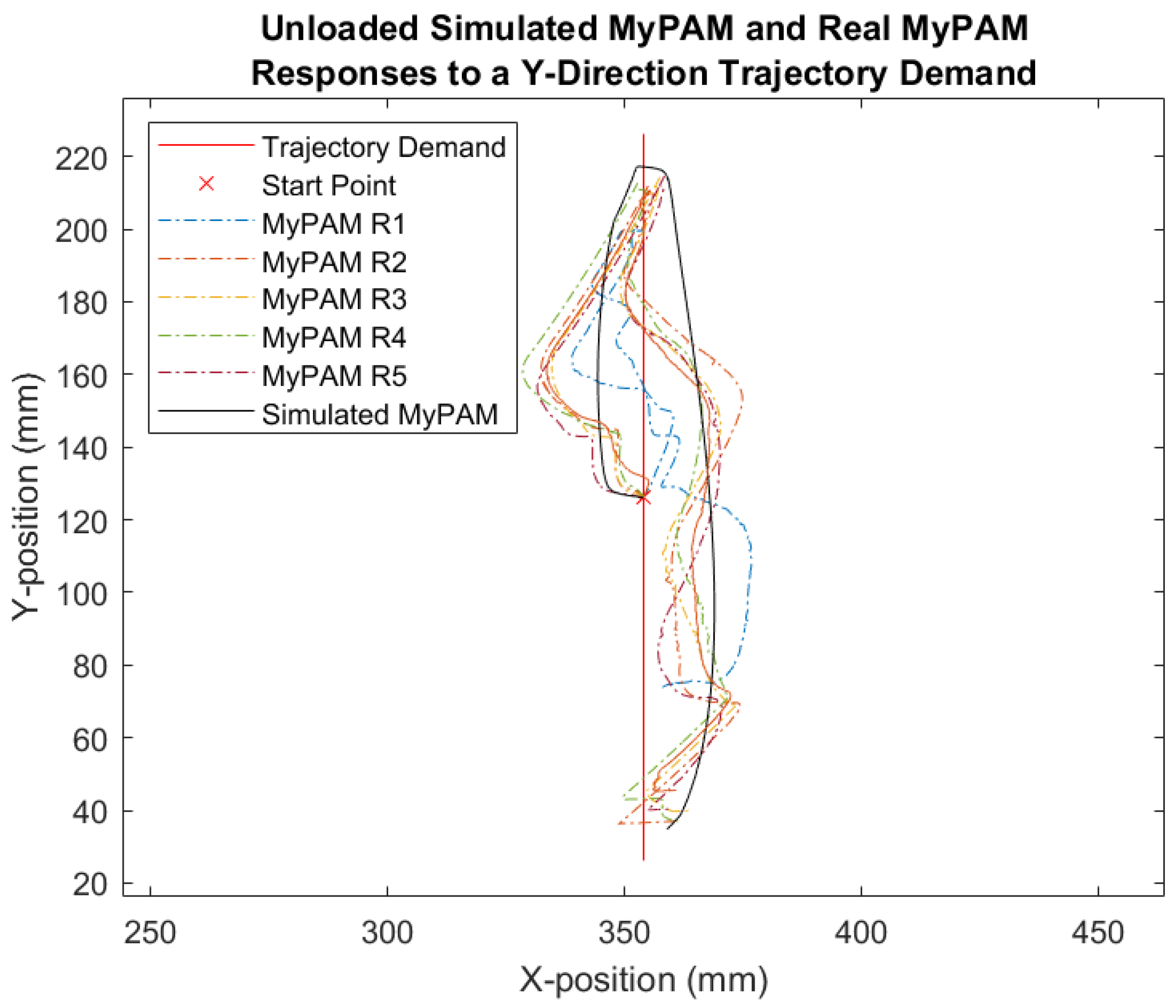
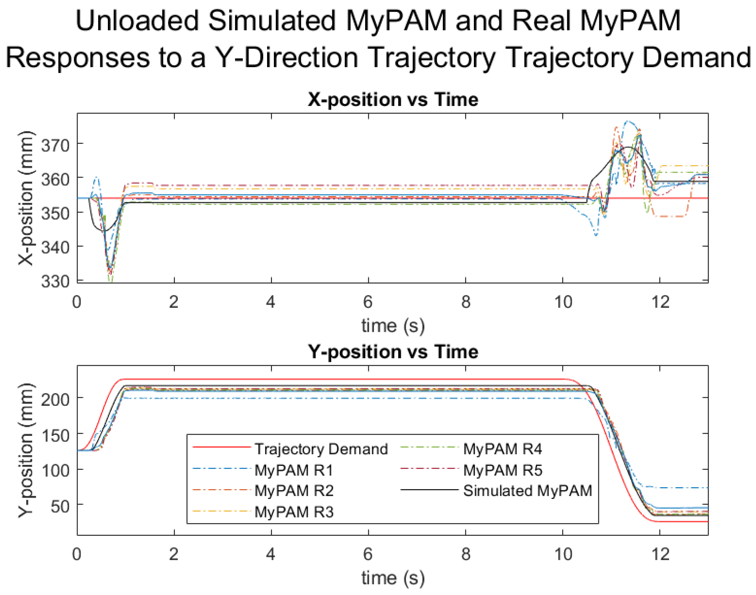
4.1. Unloaded MyPAM: Tests 1 and 2
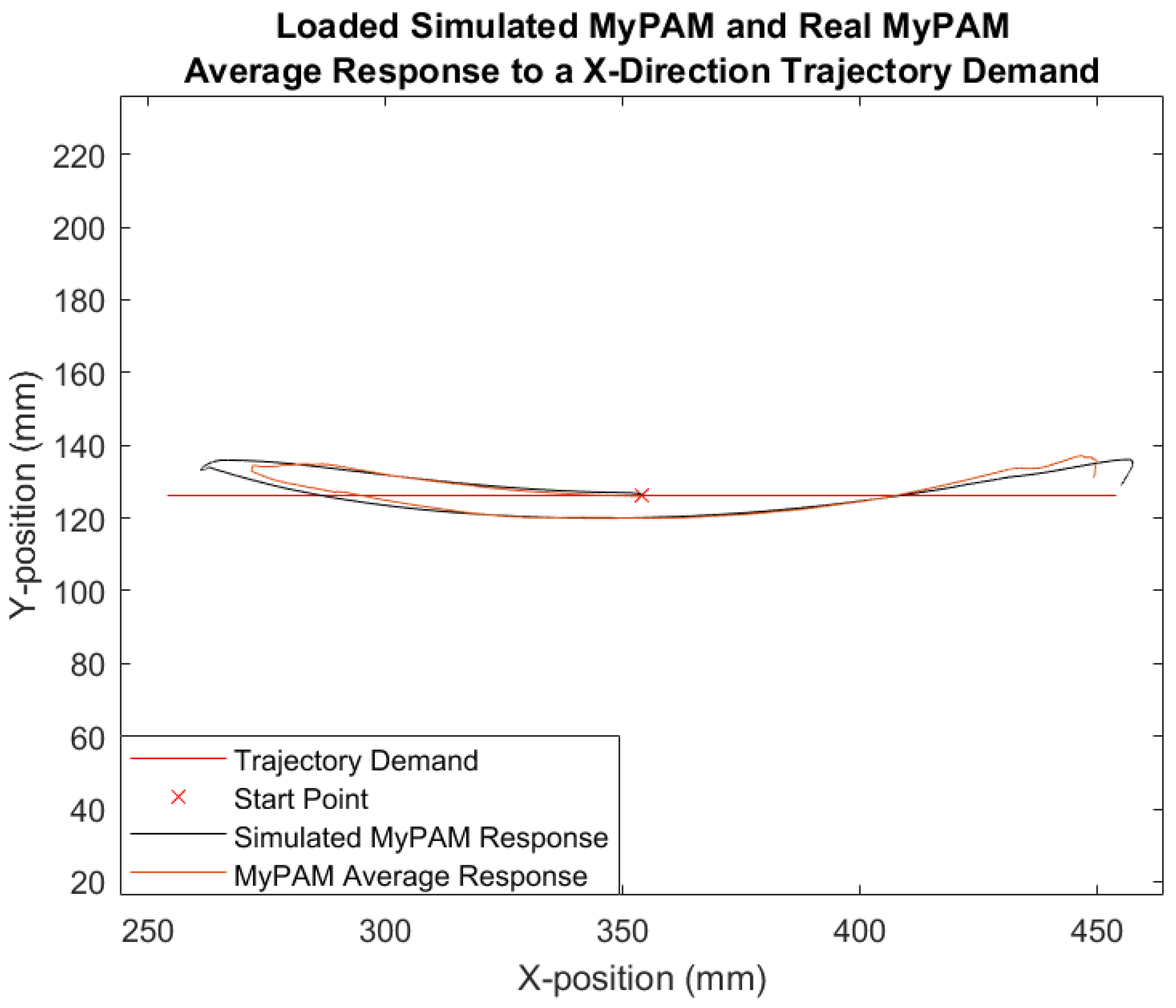
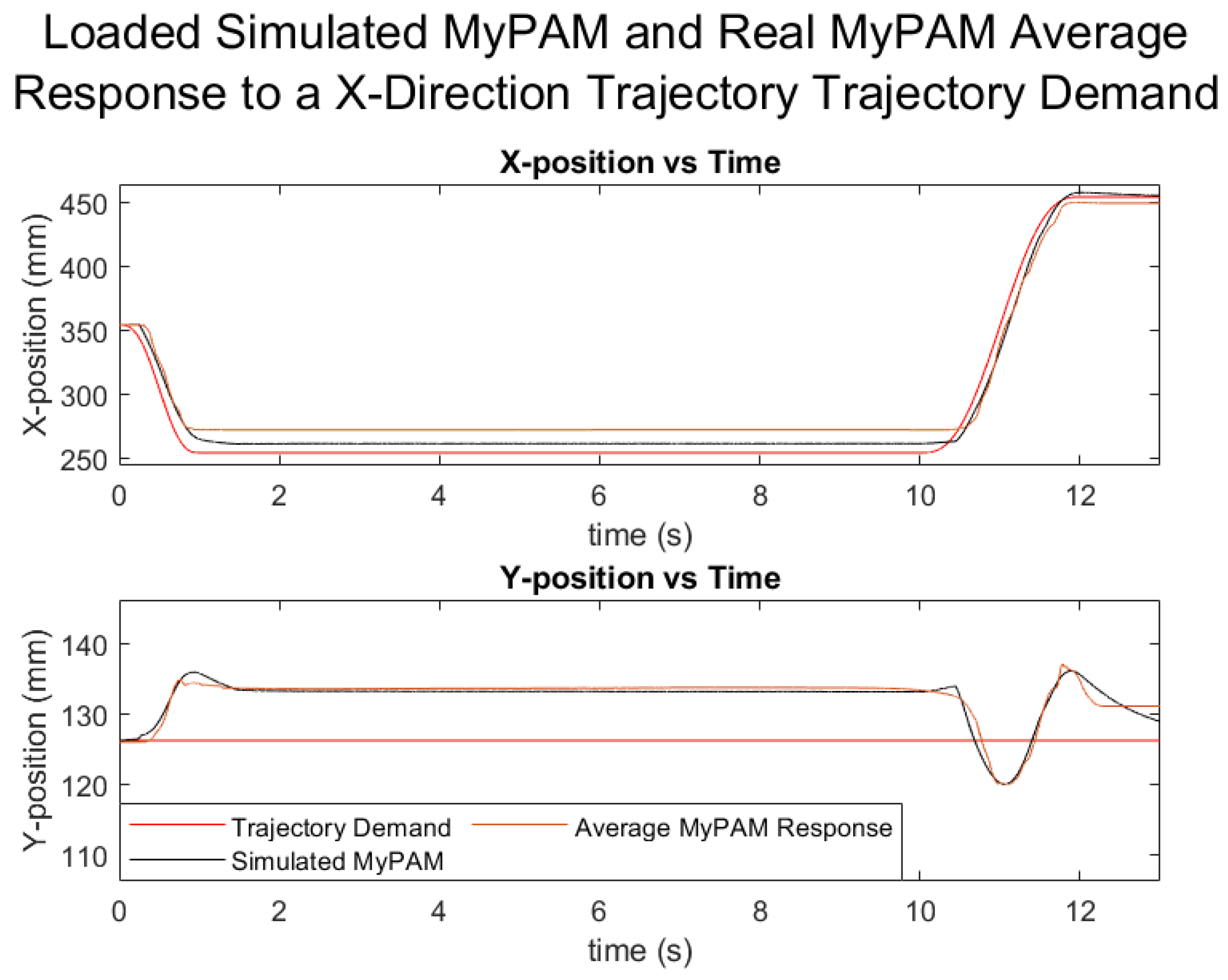
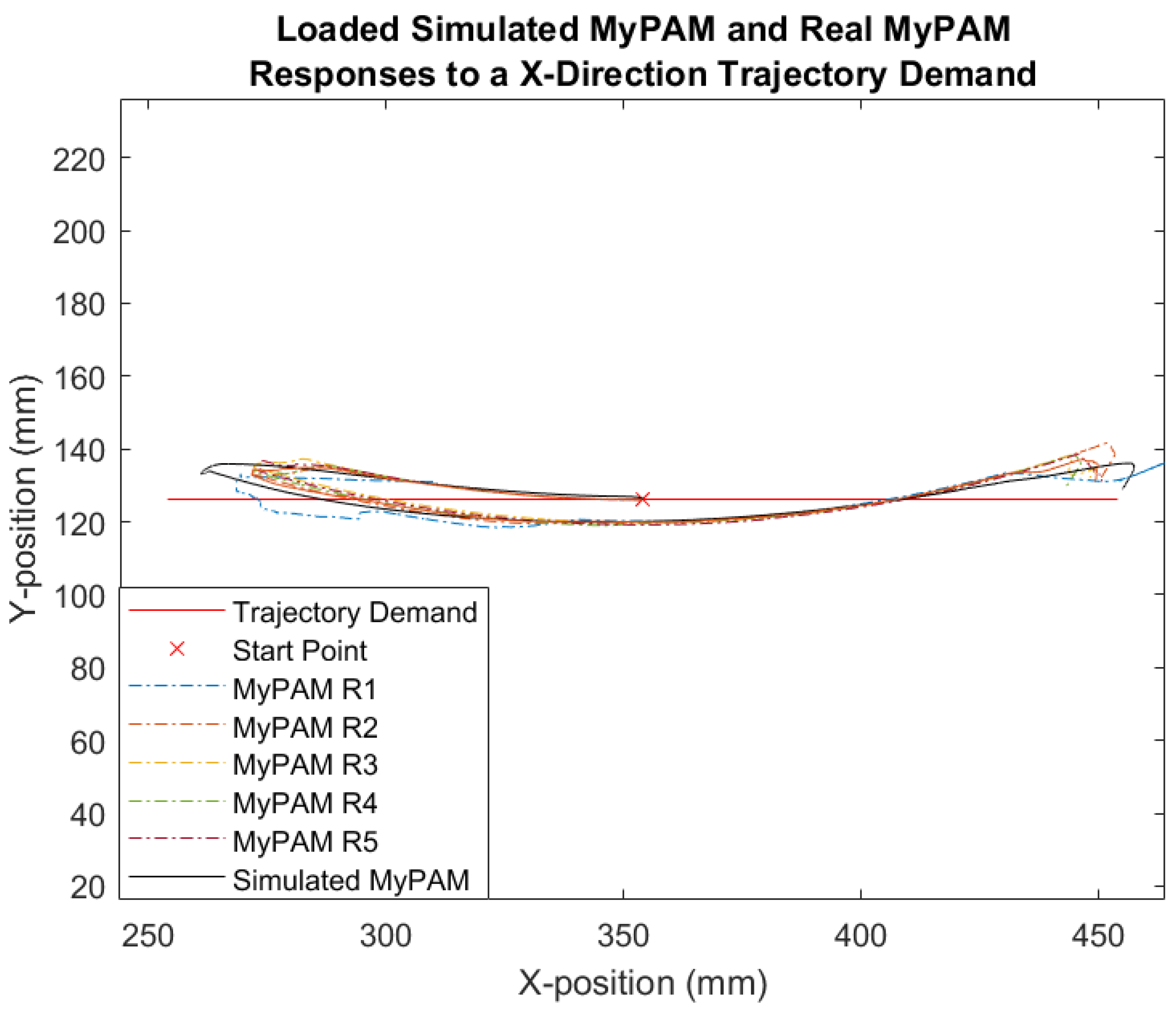
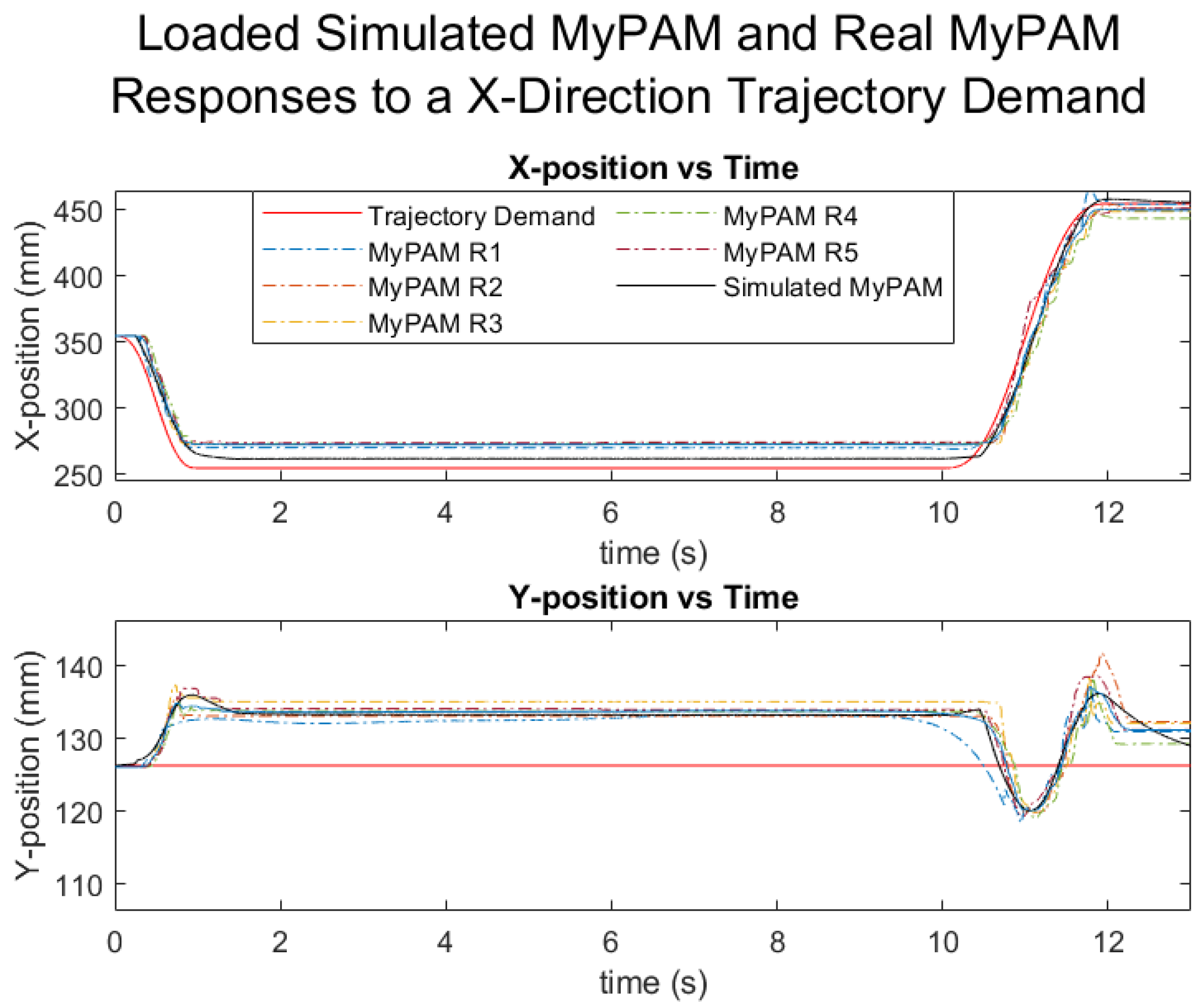
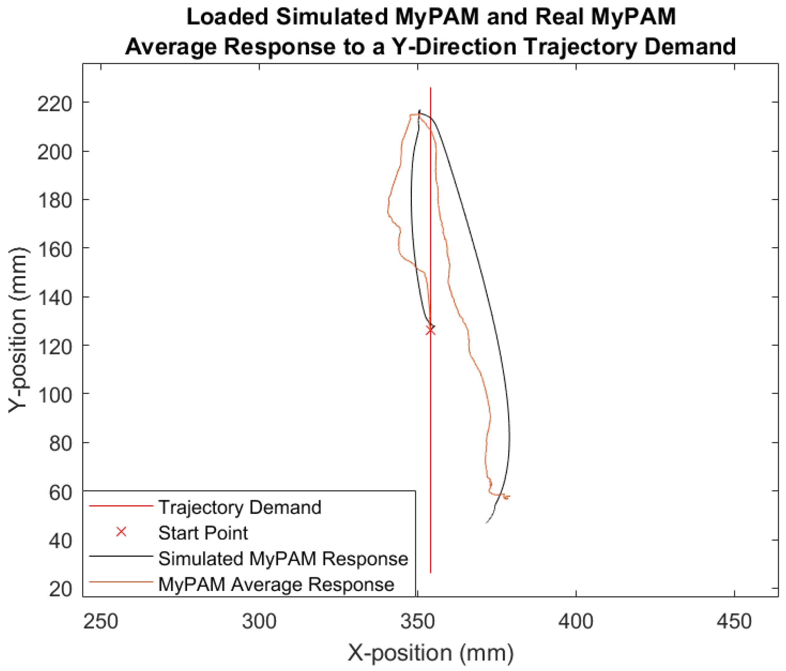
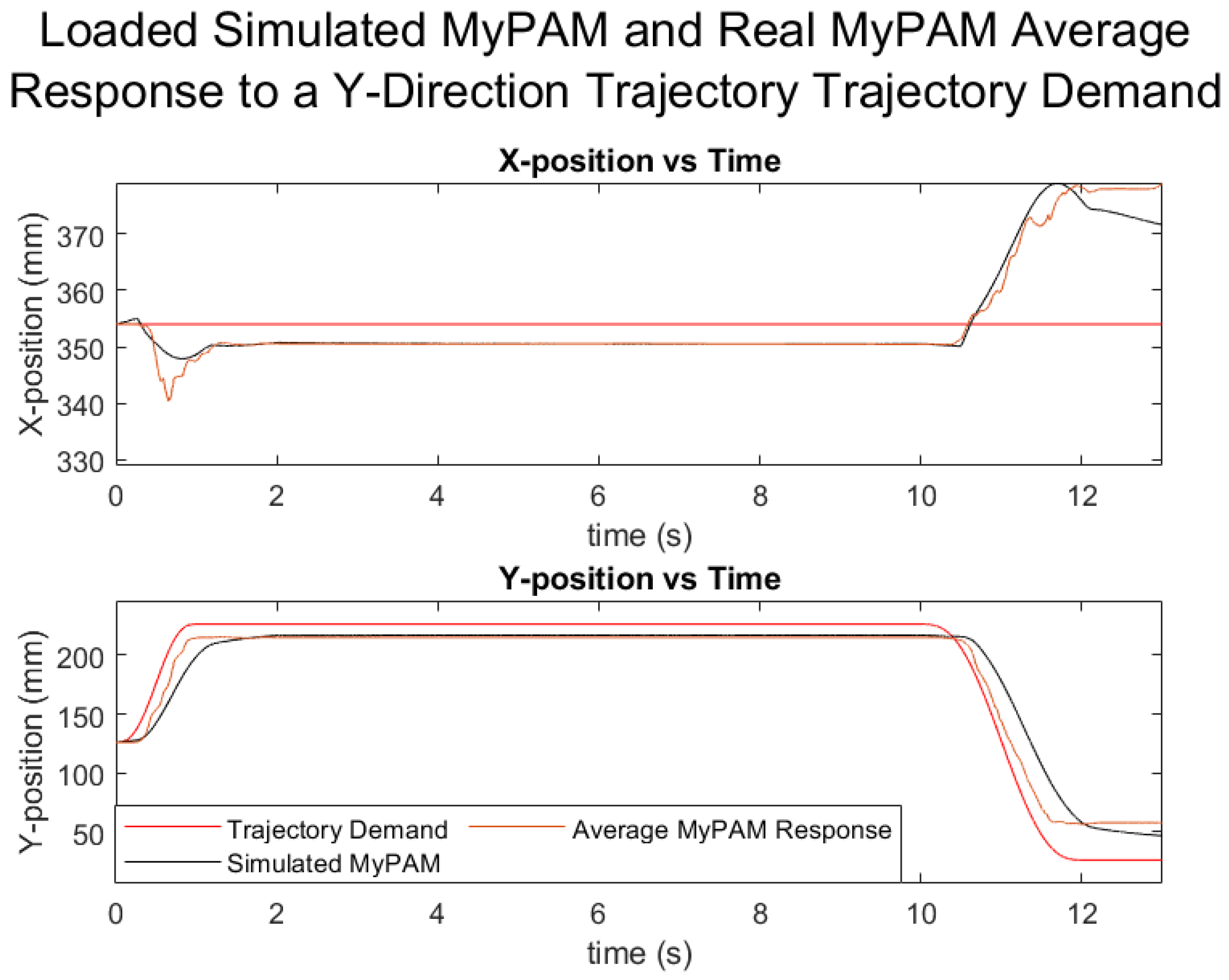
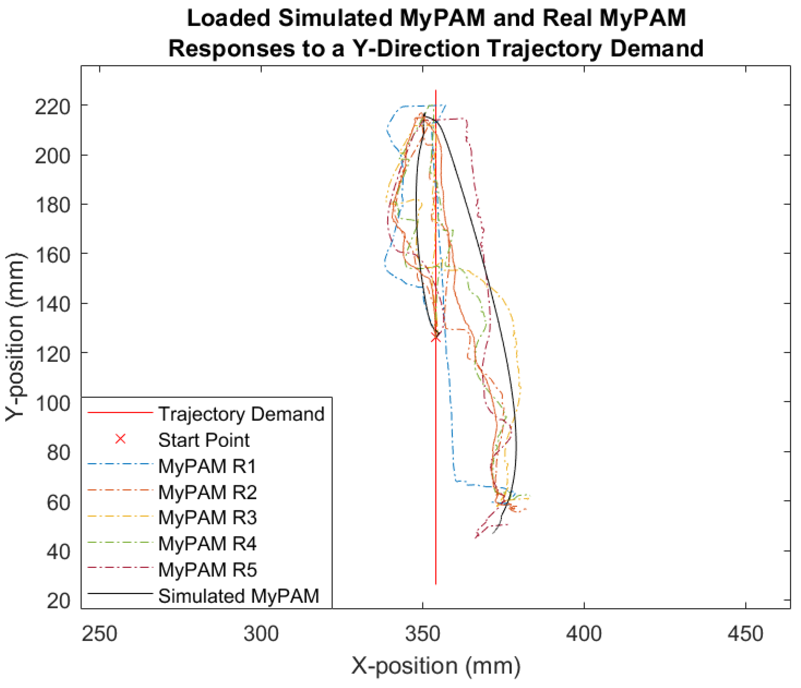
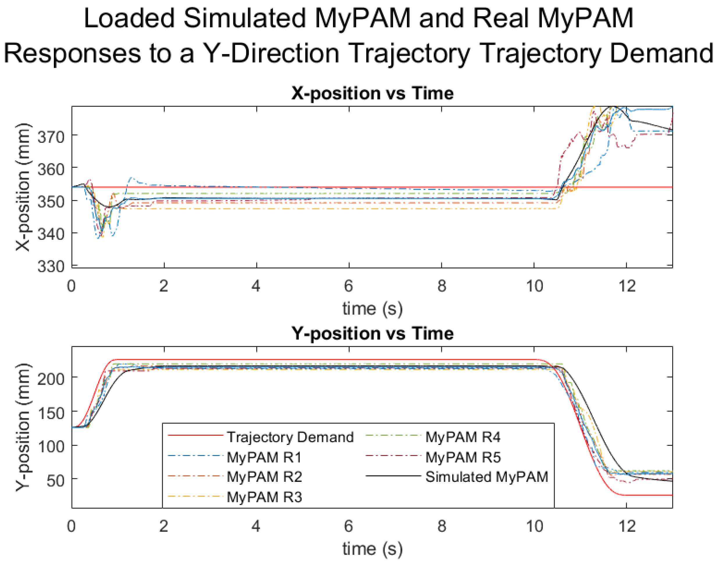
4.2. Loaded MyPAM: Tests 3 and 4
5. Discussion
6. Conclusions
Author Contributions
Funding
Institutional Review Board Statement
Informed Consent Statement
Data Availability Statement
Conflicts of Interest
References
- Flores, E.; Tobon, G.; Cavallaro, E.; Cavallaro, F.I.; Perry, J.C.; Keller, T. Improving patient motivation in game development for motor deficit rehabilitation. In Proceedings of the 2008 International Conference on Advances in Computer Entertainment Technology, Yokohama, Japan, 3–5 December 2008; pp. 381–384. [Google Scholar]
- Wafa, H.A.; Wolfe, C.D.; Emmett, E.; Roth, G.A.; Johnson, C.O.; Wang, Y. Burden of stroke in Europe: Thirty-year projections of incidence, prevalence, deaths, and disability-adjusted life years. Stroke 2020, 51, 2418–2427. [Google Scholar] [CrossRef] [PubMed]
- Alrabghi, L.; Alnemari, R.; Aloteebi, R.; Alshammari, H.; Ayyad, M.; Al Ibrahim, M.; Alotayfi, M.; Bugshan, T.; Alfaifi, A.; Aljuwayd, H. Stroke types and management. Int. J. Community Med. Public Health 2018, 5, 3715–3720. [Google Scholar] [CrossRef]
- Sulzer, J.S.; Peshkin, M.A.; Patton, J.L. Design of a mobile, inexpensive device for upper extremity rehabilitation at home. In Proceedings of the 10th International Conference on Rehabilitation Robotics, Noordwijk, The Netherlands, 12–15 June 2007; pp. 933–937. [Google Scholar]
- Sivan, M.; Gallagher, J.; Makower, S.; Keeling, D.; Bhakta, B.; O’Connor, R.J.; Levesley, M. Home-based Computer Assisted Arm Rehabilitation (hCAAR) robotic device for upper limb exercise after stroke: Results of a feasibility study in home setting. J. Neuroeng. Rehabilit. 2014, 11, 163. [Google Scholar] [CrossRef] [PubMed] [Green Version]
- Krebs, H.I.; Hogan, N.; Aisen, M.L.; Volpe, B.T. Robot-aided neurorehabilitation. IEEE Trans. Rehabilit. Eng. 1988, 6, 75–87. [Google Scholar] [CrossRef] [PubMed] [Green Version]
- Krebs, H.I.; Ferraro, M.; Buerger, S.P.; Newbery, M.J.; Makiyama, A.; Sandmann, M.; Lynch, D.; Volpe, B.T.; Hogan, N. Rehabilitation robotics: Pilot trial of a spatial extension for MIT-Manus. J. Neuroeng. Rehabilit. 2004, 1, 5. [Google Scholar] [CrossRef] [PubMed] [Green Version]
- Nef, T.; Guidali, M.; Riener, R. ARMin III–arm therapy exoskeleton with an ergonomic shoulder actuation. Appl. Bionics Biomech. 2009, 6, 127–142. [Google Scholar] [CrossRef] [Green Version]
- Klamroth-Marganska, V.; Blanco, J.; Campen, K.; Curt, A.; Dietz, V.; Ettlin, T.; Felder, M.; Fellinghauer, B.; Guidali, M.; Kollmar, A.; et al. Three-dimensional, task-specific robot therapy of the arm after stroke: A multicentre, parallel-group randomised trial. Lancet Neurol. 2014, 13, 159–166. [Google Scholar] [CrossRef]
- Rodgers, H.; Bosomworth, H.; Krebs, H.I.; van Wijck, F.; Howel, D.; Wilson, N.; Aird, L.; Alvarado, N.; Andole, S.; Cohen, D.L.; et al. Robot assisted training for the upper limb after stroke (RATULS): A multicentre randomised controlled trial. Lancet 2019, 394, 51–62. [Google Scholar] [CrossRef] [Green Version]
- Bersano, A.; Kraemer, M.; Touzé, E.; Weber, R.; Alamowitch, S.; Sibon, I.; Pantoni, L. Stroke care during the COVID-19 pandemic: Experience from three large European countries. Eur. J. Neurol. 2020, 27, 1794–1800. [Google Scholar] [CrossRef] [PubMed]
- Smith, E.E.; Mountain, A.; Hill, M.D.; Wein, T.H.; Blacquiere, D.; Casaubon, L.K.; Linkewich, E.; Foley, N.; Gubitz, G.; Simard, A.; et al. Canadian stroke best practice guidance during the COVID-19 pandemic. Can. J. Neurol. Sci. 2020, 47, 474–478. [Google Scholar] [CrossRef] [PubMed]
- Kristoffersen, E.S.; Jahr, S.H.; Faiz, K.W.; Storstein, A.M.; Winsvold, B.S.; Sandset, E.C. Acute stroke care during the first phase of COVID-19 pandemic in Norway. Acta Neurol. Scand. 2021, 143, 349–354. [Google Scholar] [CrossRef] [PubMed]
- Douiri, A.; Muruet, W.; Bhalla, A.; James, M.; Paley, L.; Stanley, K.; Rudd, A.G.; Wolfe, C.D.; Bray, B.D.; SSNAP Collaboration. Stroke care in the United Kingdom during the COVID-19 pandemic. Stroke 2021, 52, 2125–2133. [Google Scholar] [CrossRef] [PubMed]
- Stroke Recoveries at Risk Report. Available online: https://www.stroke.org.uk/stroke-recoveries-at-risk-report (accessed on 5 December 2021).
- y Galán, J.T.G. Stroke as a complication and prognostic factor of COVID-19. Neurología (Engl. Ed.) 2020, 35, 318–322. [Google Scholar] [CrossRef]
- Wang, C.C.; Chao, J.K.; Wang, M.L.; Yang, Y.P.; Chien, C.S.; Lai, W.Y.; Yang, Y.C.; Chang, Y.H.; Chou, C.L.; Kao, C.L. Care for patients with stroke during the COVID-19 pandemic: Physical therapy and rehabilitation suggestions for preventing secondary stroke. J. Stroke Cerebrovasc. Dis. 2020, 29, 105182. [Google Scholar] [CrossRef] [PubMed]
- Lynch, K.M.; Park, F.C. Modern Robotics, 1st ed.; Cambridge University Press: Cambridge, UK, 2017; p. 231. [Google Scholar]
- Erez, T.; Tassa, Y.; Todorov, E. Simulation tools for model-based robotics: Comparison of bullet, havok, mujoco, ode and physx. In Proceedings of the 2015 IEEE International Conference on Robotics and Automation (ICRA), Seattle, DC, USA, 26–30 May 2015; pp. 4397–4401. [Google Scholar]
- Das, S. Modeling and Simulation of Mechatronic Systems Using Simscape, 1st ed.; Morgan and Claypool Publishers: San Rafael, CA, USA, 2020; pp. 11–23. [Google Scholar]
- Jackson, A.E.; Levesley, M.C.; Culmer, P. Development of a mechanical arm model of the human arm for use with an exercise robotic system being developed for people with stroke. In Proceedings of the 2nd Cambridge Workshop on Universal Access and Assistive Technologies, Cambridge, UK, 22–24 March 2004; pp. 91–98. [Google Scholar]


| Parameter | DC Motor Block (Joint 0) | DC Motor Block (Joint 1) |
|---|---|---|
| Armature Resistance (Ohm) | 0.299 | 0.331 |
| Armature Inductance (mH) | 0.082 | 0.103 |
| Torque Constant (mNm/A) | 30.2 | 27.3 |
| No-load Current (A) | 0.137 | 0.164 |
| Nominal Voltage (V) | 24 | 24 |
| Rotor Inertia (g cm2) | 142 | 72.8 |
| Parameter | Joint 0 | Joint 1 |
|---|---|---|
| Breakaway Friction Torque (Nm) | 0.25 | 0.29 |
| Breakaway Friction Velocity (rad−1) | 0.1 | 0.1 |
| Coulomb Friction Torque (Nm) | 0.18 | 0.23 |
| Viscous Friction Torque (Nm/rad−1) | 0.181 | 0.372 |
| Test | MyPAM Loading Condition | Trajectory Direction |
|---|---|---|
| 1 | Unloaded | X-Direction |
| 2 | Unloaded | Y-Direction |
| 3 | Loaded | X-Direction |
| 4 | Loaded | Y-Direction |
Publisher’s Note: MDPI stays neutral with regard to jurisdictional claims in published maps and institutional affiliations. |
© 2021 by the authors. Licensee MDPI, Basel, Switzerland. This article is an open access article distributed under the terms and conditions of the Creative Commons Attribution (CC BY) license (https://creativecommons.org/licenses/by/4.0/).
Share and Cite
Metcalf, A.G.; Gallagher, J.F.; Jackson, A.E.; Levesley, M.C. Multi-Domain Dynamic Modelling of a Low-Cost Upper Limb Rehabilitation Robot. Robotics 2021, 10, 134. https://doi.org/10.3390/robotics10040134
Metcalf AG, Gallagher JF, Jackson AE, Levesley MC. Multi-Domain Dynamic Modelling of a Low-Cost Upper Limb Rehabilitation Robot. Robotics. 2021; 10(4):134. https://doi.org/10.3390/robotics10040134
Chicago/Turabian StyleMetcalf, Adam G., Justin F. Gallagher, Andrew E. Jackson, and Martin C. Levesley. 2021. "Multi-Domain Dynamic Modelling of a Low-Cost Upper Limb Rehabilitation Robot" Robotics 10, no. 4: 134. https://doi.org/10.3390/robotics10040134
APA StyleMetcalf, A. G., Gallagher, J. F., Jackson, A. E., & Levesley, M. C. (2021). Multi-Domain Dynamic Modelling of a Low-Cost Upper Limb Rehabilitation Robot. Robotics, 10(4), 134. https://doi.org/10.3390/robotics10040134