Article

Development and Usability Testing of a Finger Grip Enhancer for the Elderly

1
Faculty of Engineering and Technology, Multimedia University, Jalan Ayer Keroh Lama, Bukit Beruang, Melaka 75450, Malaysia
2
Department of Industrial Engineering, President University, Jababeka Education Park, Jl. Ki Hajar Dewantara, RT.2/RW.4, Mekarmukti, North Cikarang, Bekasi 17530, Indonesia
3
Department of Orthopaedic Surgery, University of Malaya Medical Centre (UMMC), Jln Profesor Diraja Ungku Aziz, Kuala Lumpur 59100, Malaysia
4
Department of Social Science and Humanities, Putrajaya Campus, College of Energy Economics and Social Sciences, Universiti Tenaga Nasional (UNITEN), Jalan IKRAM-UNITEN, Kajang 43000, Malaysia
*
Author to whom correspondence should be addressed.
Robotics 2022, 11(1), 5; https://doi.org/10.3390/robotics11010005
Submission received: 21 October 2021 / Revised: 14 December 2021 / Accepted: 28 December 2021 / Published: 30 December 2021
(This article belongs to the Special Issue Kinematics and Robot Design IV, KaRD2021)

Abstract

:
As people age, their finger function deteriorates due to muscle, nerve, and brain degeneration. While exercises might delay this deterioration, an invention that enhances elderly people’s pinching abilities is essential. This study aims to design and develop a finger grip enhancer that facilitates the day-to-day pinching activities of elderly people. This research is an extension of a previous study that conceptualised a finger grip enhancer. The device facilitates finger flexion on the thumb and index finger, and weighs 520 g, allowing for improved portability and sufficient force exertion (13.9 N) for day-to-day pinching. To test for usability, eleven subjects aged 65 years and above performed a pinch-lift-hold test on various household objects. The pinch force before and after utilising the device was measured. Using Minitab 18, the statistical significance of using this device was analysed with a paired-samples t-test. With this device, the elderly people’s pinching abilities significantly improved in both pinch force and pinch force steadiness (p < 0.05). The proposed device has the potential to enhance elderly people’s quality of life by supporting a firm pinch in the handling of everyday objects. This research has applicational value in developing exoskeleton devices for patients who require rehabilitation.

1. Introduction

The elderly’s struggle in maintaining an active and healthy lifestyle in a fast-growing population of elderly people is becoming a serious concern in the world [1,2]. Degradation of fine motor skills and hand functions occur among elderly people due to nerve, brain and muscle degeneration [3,4]. In studies concerning elderly people’s involvement in basic activities of daily living (ADL), poor hand strength causes even the screwing or unscrewing of medicine bottle caps to be daunting tasks [5,6]. Similarly, elderly people can struggle with simple pinch grip activities.
Researchers found that the handgrip strength and ADL scale values of elderly adults were greatly improved by the combined use of finger-movement exercises and correct finger weight-lifting training, and these rehabilitation activities can be utilised to assist the elderly in maintaining their ability to care for themselves [7]. Through finger exercise training regimens, researchers found that trained older adults showed significant gains compared to untrained senior citizens in the ability to control submaximal pinch force, maintain a steady hand posture, and transfer small objects with finger grips following expert finger movement training [8]. Similar benefits from hand exercise programmes have even been observed for people with hand-related rheumatoid arthritis [9,10], dementia [11], and chronic upper limb conditions [12].
While exercises can aid the survival of motor units (MU), reinnervation and neuromuscular junction morphology, the ageing MU has diminished plasticity in response to physical activity, particularly in an advanced age where exercise training might over-burden the remodelled surviving MUs and exacerbate their demise [13]. Hence, frail elderly people who experience severe weakness in their hands might need urgent medical attention. One possible solution to address this weakness is by researching exoskeleton devices. Hand exoskeletons can be broadly divided into two categories, namely rehabilitation and assistive exoskeletons. Rehabilitation exoskeletons are often used to help stroke patients [14,15,16,17], patients with limited hand motor functions [16,18], and patients who suffer from hand injuries [18,19]. Due to the similarity in construction, assistive components are sometimes incorporated into rehabilitation devices [20,21] or constructed to treat a specific condition such as paralysis of the fingers [22,23].
In a recent National Health and Morbidity Survey conducted by Mahmud, et al. [24], elderly peoples’ functional limitations in performing ADL were investigated. Most of the activities required good hand and finger mobility such as grooming, toilet use, feeding and dressing. The findings revealed that 17% of the elderly people had functional limitations of which females (21.2%) had a higher prevalence compared to males (12.7%). These statistical findings highlighted the neglected quality of life among the elderly due to poor finger abilities.
Numerous pieces of research have been done on finger gripping through population-based data [13,14,15], determinants that affect pinch strength [16,17,18], and pinch strength effects on ADL [18,19]. Many of these studies are statistical by nature and look into providing fundamental inferences of pinch health along with their effects on people and society. However, exoskeleton devices specifically designed to assist in finger pinching are few and uncommon. In previous research, the theory of inventive problem solving (TRIZ) was used to systematically synthesise and select a finger grip enhancer concept powered by a miniature linear actuator that actuates the fingers through tendon cables triggered by a push start button [25]. Therefore, the aim of the present study is to extend from this previous research by designing and developing a finger grip enhancer that facilitates the day-to-day pinching activities of elderly people.

2. Literature Review

2.1. Conceptual Design

The concept of the present study was conceptualised and selected from a previous study [25]. When designing a finger exoskeleton, the anatomy of the hand is a priority. The anatomical measurements include length, width and circumference [26,27]. The range of motion (ROM) of fingers and wrist (flexion, extension, abduction, adduction) is also a common functional measurement. With the objective of assisting elderly people in daily pinch activities, the ROM that the device must cover is that of pinch prehension.
The palmar pinch was found to be the most commonly used prehension. It was found to be used 50% of the time for picking-up situations and 88% of the time for hold-for-use situations when considering palmar, tip and lateral prehensions [28]. During palmar prehension, the hand system is found to have the following characteristics:
  • Wrist is in slight extension.
  • Metacarpophalangeal flexion with slight phalangeal flexion.
  • Flexion of the thumb’s interphalangeal (IP) joint and index finger’s distal interphalangeal (DIP) joint [29].
The constraints of the human hands were technically presented by Lin, et al. [30]. The three types of constraints are listed below. The mechanical limitation of the hand was considered during the design phase by studying the max ROM of each finger joint.
  • Each finger has a limited motion range due to the mechanical limitation of hand anatomy.
  • In each finger, the DIP joint and proximal interphalangeal (PIP) joint always move together.
  • People have a habit of making standard gestures, where they usually bend all the fingers at the same time to make a fist, instead of one by one.
Generally, a hand exoskeleton can have one of three main objectives, namely rehabilitation, assistive use or haptic use [31]. An assistive exoskeleton is for patients with hand disabilities to assist them during activities of daily living (ADL) which can include holding a key, plugging a power adapter, buttoning and unbuttoning a shirt, or picking up small fruit.
A direct matching mechanism includes a series of linkages connected to mirror the movement of fingers. This concept is one of the simplest underactuated mechanisms attached to the side and back of the fingers. The current study has adopted the tendon-driven mechanism that imitates the flexor digitorum tendons (profundus and superficialis), which is the tendon responsible for finger flexion [32].
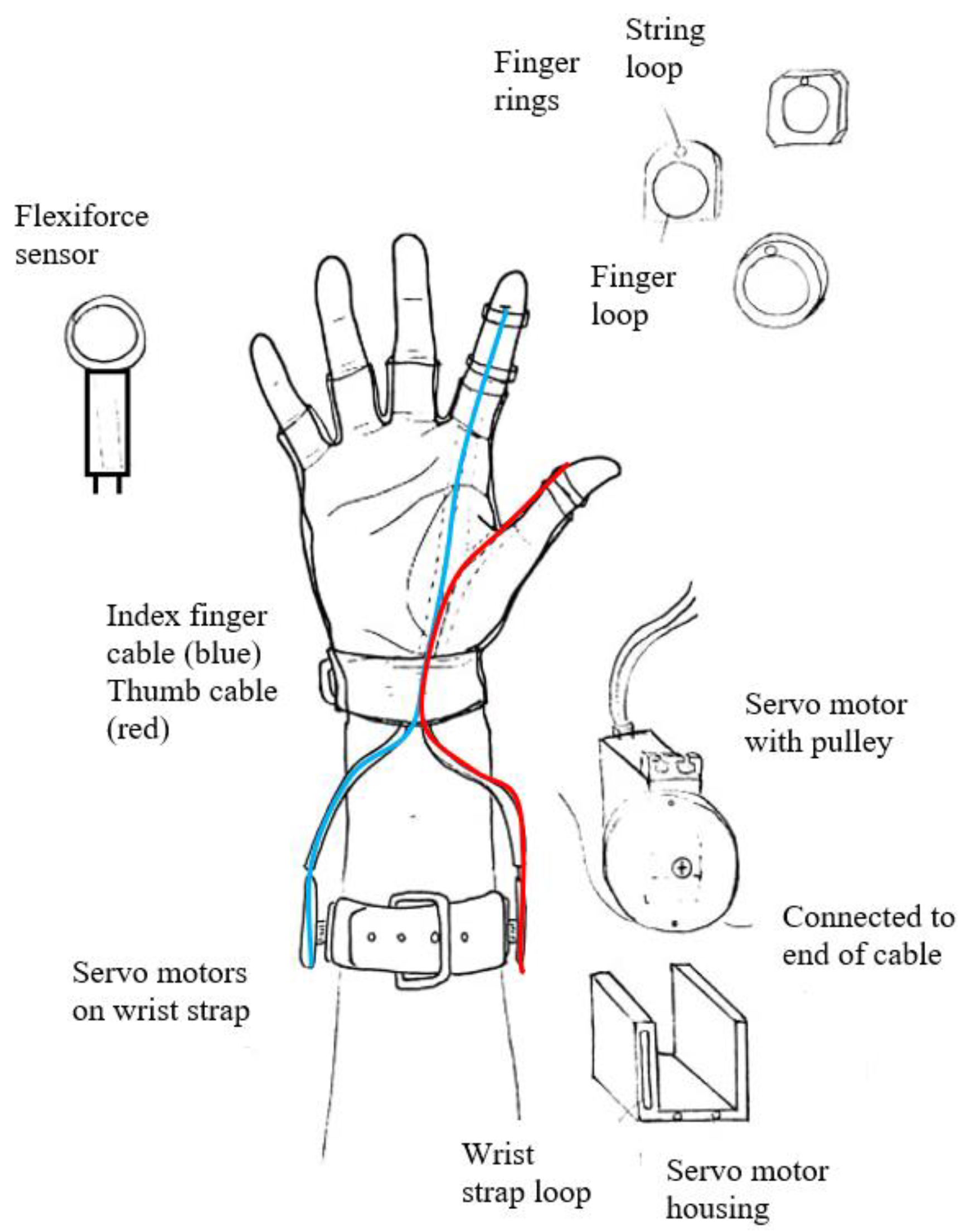
The underactuated mechanism in this study’s application is not required for finger extension as this action is done naturally by the fingers. Actuation of the fingers is accomplished through the tensioning of artificial tendons or string cables on the palmar side of the hand. The device needs to assist in finger flexion, and includes wires underneath the fingers and pivot points at the finger joints as seen in Figure 1.
The human hand has 27 degrees of freedom (DOF): 5 DOF in the thumb, 4 (3 for extension/flexion and 1 for abduction/adduction) for each of the other 4 fingers and 6 more in the wrist for translation and rotation [33]. However, for the purpose of designing an exoskeleton or prosthetic device for the hand, many researchers proposed simplified models with less DOF. Lisini, et al. [34] used a simplified kinematic structure with 23 degrees of freedom while Lince [35] designed the ReHand exoskeleton device to accommodate 24 DOF of the hand.
With the device actuated by flexible cables, it gives users freedom in both finger and hand movements. This concept enables the researchers to ignore some DOFs in the prototype while still allowing users to freely control all the ROM of the fingers. The ideal wrist position during any pinching action is a neutral position as deviation from that position was found to reduce pinch force [36]. Thus, the wrist joint is not included in the design of the device. This strategy was also applied by Worsnopp, et al. [37] as most pinching movements involve fingers with neutral abduction or adduction.
Furthermore, a two-finger pinch relies mostly on the flexion of the finger joints which allowed the researchers to ignore the abduction/adduction of joints. Thus, to achieve the goal of assisting the elderly in pinching, the device assisted in 5 DOF, of which two are in the thumb and three are in the index finger.

2.2. Design Subassembly

Each subassembly of the pinch enhancer is explained in this section for a more detailed understanding of how different parts with different functions come together. Figure 2 is the subassembly tree diagram of the pinch enhancer which is broken down into three main components, namely the control system, actuation assembly and palm assembly.
Figure 3 shows the device divided into its subassemblies. With the user’s right hand equipped with the device, the first pinch is initiated. Once their fingers have pinched the objects, the force-sensitive resistor is pressed using their left hand. This operation will indicate that a pinch action is taking place and trigger the device to rotate. The rotation of the servo is based on the amount of force applied from the left hand on the force-sensitive resistor. This method of using both hands to control the action was also studied by Leonardis, et al. [38] and Rahman and Al-Jumaily [15]. For different digit sizes, different finger rings are used to ensure a good fit between the fingers and the device. In a hand exoskeleton, Sarac, Solazzi and Frisoli [31] categorised the design aspect into four different categories: mobility, mechanical design, actuation and operational strategies. A similar categorisation is also discussed in the following sections.

2.3. Actuation

Figure 4 illustrates the transmission of a phalange in a finger flexion to achieve a pulp pinch. The device does not control the rotation of the thumb’s carpometacarpal (CMC) joint which is only required for hard linkage designs. The reason is due to the flexibility of the current system which is similar to the flexibility in soft robotics. The CMC joint has its uninterrupted natural ROM during pinching tasks. This condition also applies to the abduction and adduction of both fingers.
Alexander and Kotiuk [39] investigated the length of hand segments of 66 adult patients aged 19 to 78 years. After the age of 18 years, changes in the proportions of the hand segments are normally considered to be insignificant [40]. Table 1 shows the extraction of segment lengths for the thumb and index finger [39].
The underactuated design depends on the change in length, L. The change in length, ∆L, will translate to the rotational displacement of the phalanges about their respective joints. This movement is estimated to follow a perfect arc trajectory thus allowing for the use of circular equations. In order to measure the ROM of the fingers, Hume, et al. [41] used both a standard goniometric and electro goniometric method to obtain maximum joint measurements of the fingers. Jahn, et al. [42] used a video motion capture technology to measure the ROM of joints while sustaining a pulp pinch. Table 2 shows the extraction of their experimental results [41,42].
The ∆L is a linear displacement that is achieved by the rotation of a DC servo motor. When ∆L increases, the tendon cables are pulled, creating deflection joint angles θM, θP and θD. Therefore, the rotation translation of the motor must be sufficient to transform the linear displacement of the fingers such that the pinch joint ROM can be achieved. For safety purposes, the ∆L must not cause the tendon cables to excessively pull the finger until the joints exceed their maximum ROM.
The average ∆L required to rotate all three joints for a pulp pinch can be calculated through Equations (1) and (2). The servo motor requires a rotational displacement which corresponds to the 40.16 mm linear displacement.
Δ L = s M + s P + s D
Δ L = r M θ M + r P θ P + r D θ D
Δ L = 40.16   mm
This requirement is determined by calculating the arc of the pulley (see Equation (3)). The potentiometer servo motor has a 180-degree rotation. Therefore, the motor pulley requires a minimum diameter of 25.57 mm but is finally designed with a 45 mm diameter. A larger diameter pulley produces a larger moment and also greater adjustment flexibility.
s = r θ
2 r = d = 25.57   mm

2.4. Servo Unit

The servo unit is tasked to pull the cables connected to the fingers which mimic how the hand muscles function. The selected servo requires a stall torque that is greater than the extension force of the fingers. This requirement is important to prevent the fingers from losing their grip which may result in the pinched object falling from the grasp. Table 3 presents the mean extension force of the index finger for both men and women [43].
The servo pulley was previously designed to have a diameter of 45 mm. Using the mean extension force of men at 40.6 N, the servo’s required stall torque is calculated with Equation (4).
τ stall > Fr
τ stall > 913.5   Nmm
τ stall > 9.31   kg   cm
The stall torque of the servo should be at least 9.31 kg cm. Therefore, a Feetech metal gears analogue servo with a 15 kg cm stall torque is selected. The maximum holding force that the motor can generate is 65.4 N.
A servo housing unit is designed to hold the servos in place and is strapped onto the forearm to minimise mass added to the fingers. The force is transmitted through the cables. The cables follow the cable guide from the fingers through the glove and all the way to each servo motor (see Figure 5). The unit is 3D printed with PLA plastic which is durable and lightweight. The housing unit does not fully enclose the servos which enable easy access for technical adjustments.

2.5. Control System

Figure 6 shows a diagram for determining the most suitable control device to be used in this project. From this control flow, the number of I/O (input/out) pins required are listed in Table 4. The two-finger control device is simply a single input single output control system that receives input data in the form of finger pressure force, processes it before rotating the servo motors based on the required angle (output). The control units will then receive the analogue input from the fingers through the force-sensitive resistors, indicating that a pinch action has begun (Figure 6b). From Figure 6c, the “if” statement is used as a logic decision that constantly checks for the input value. This analogue value will then be processed by the control unit which maps that value to the corresponding servo output (Figure 6d). The servo rotates to that specific position which provides tension to the fingers (Figure 6e). The control units will then continue to check the input signal until the analogue value becomes zero which indicates that the pinch action has been completed. Correspondingly, it will signal the servo to return to the zero position which relaxes the fingers.
To further elaborate on Figure 6c,d which are the devices main programming logic, the map function used to determine the servo rotation has the following syntax:
map ( value ,   from   Low ,   from   High ,   to   Low ,   to   High )
With the map function, the Arduino is programmed as follows:
Servoposition 0 = map ( fsrReading   0 ,   200 ,   500 ,   0 ,   170 )
This map function is used to re-map the input value from the force-sensitive resistor to the servo output rotation. The sensor is connected to the 10-bit analogue pin0 which has a digital value between 0 to 1023. The digital value ranging from 200 to 500 is obtained through calibrations. The lower limit of 200 is used to prevent the device from mistaking any slight mistouches as actual pinches. The sensor does not produce values above 500 even after excessive pressing. In other words, the force-sensitive resistor (FSR) converts the analogue signals received by the sensors into digital signals. The microcontroller receives digital signals between 200 and 500 which are the digital representation of the fingers’ applied pressure. Finally, mathematical logic is used to scale the 200 to 500 reading into servo rotation which in this case is between 0 and 170 degrees. This control is made possible due to the inclusion of the servo library while using the servo.write(angle) function. In this case, the “map to” values between 0 to 170 translate to a 0 to 170 degree rotation of the servo motor.
Figure 7 shows the electrical design of the device. The system can be divided into the Arduino unit, servo motors, force-sensitive resistors, a force-to-voltage circuit and a negative voltage generator circuit. The Arduino is the central unit of this design receiving analogue input from the Flexiforce sensor (Tekscan, Inc., South Bosto, MA, USA) and converting it into digital output for the servo motors. Besides using a force-sensitive resistor (FSR), other measuring devices include torque sensors and EMG sensors. The FSR was selected in this application because of its low price and its ease of use compared to EMG sensors which can be highly sensitive to changes in skin conductivity. Besides these sensors, Shojaei Barjuei, et al. [44] used a dynamic bond graph modeling method to analyse the effects of variables on an industrial back exoskeleton.
Based on the sensor manufacturer, an inverting operational amplifier (LM324) is needed to produce an analogue output as a means of calibration. This circuit also requires a −5 V DC excitation voltage which is the purpose of the negative voltage generator circuit. The 555-oscillator is used to supply a constant negative voltage to the capacitors.

3. Materials and Methods

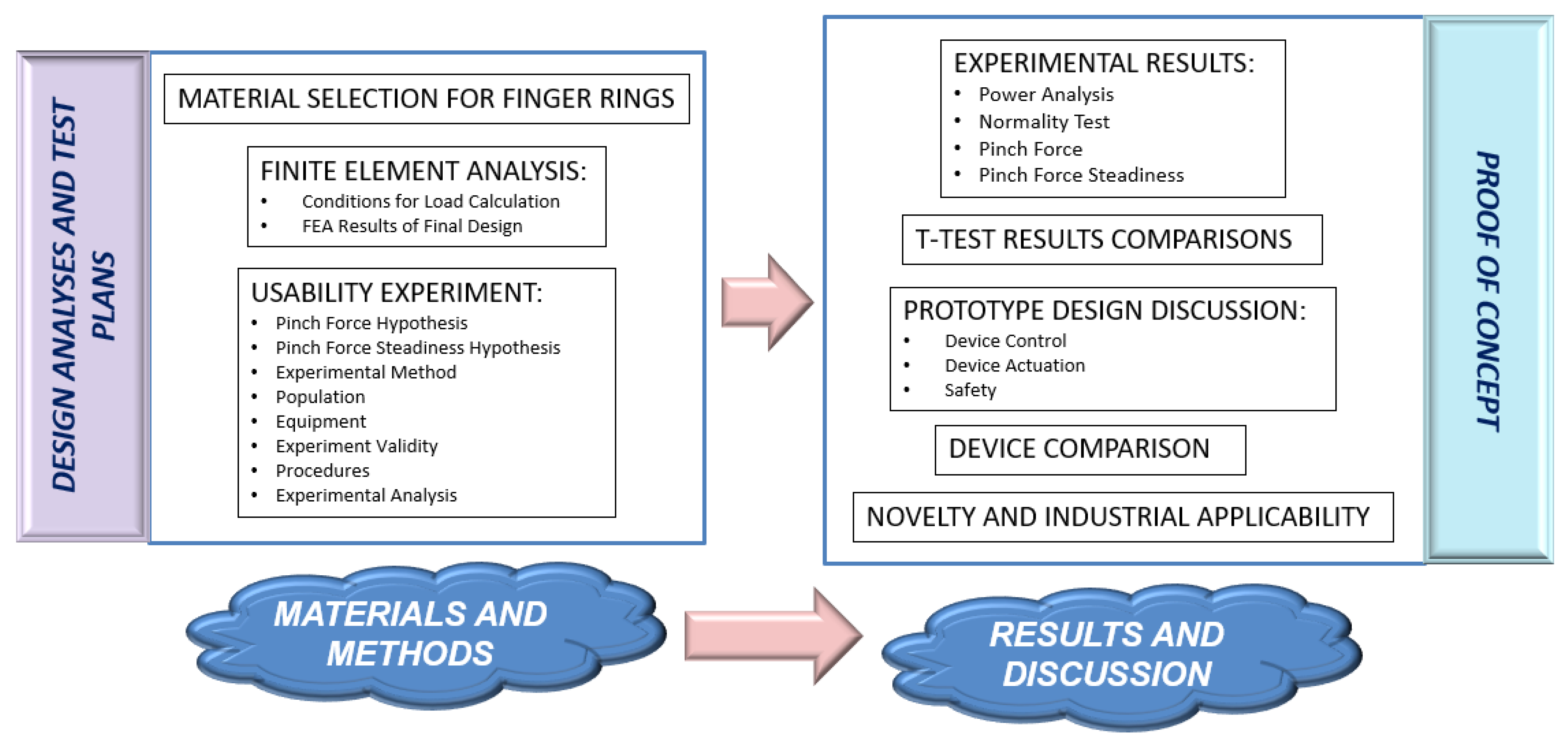
This section clarifies the design analyses, test plans and proof of concept for the proposed invention. The design analyses and test plans which are under the materials and methods section account for the material selection of the finger rings, finite element analysis, and usability experiment. The proof of concept which is under Section 4 accounts for experimental results, t-test results comparisons, prototype design discussion, device comparison, and novelty and industrial applicability. Figure 8 presents the framework of the entire process.
The following section discusses the material selection process for the finger ring component. After establishing the design requirements and objectives, the Ashby chart was used for initial material screening. Prospective materials and their properties were tabulated. The pairwise comparison table was used to determine the weightage of each criterion as not all criteria are equally important in achieving the design objective. Finally, the materials’ properties were scaled accordingly and a cost-adjusted weighted property index became the final selection score. The methodology applied here was referenced from Lampman and Dieter [45].

3.1. Material Selection Finger Rings

The function, constraints and objective in Table 5 guided the material selection process in choosing the lightest and strongest possible material.
The versatility of FDM rapid prototyping allows for a variety of building materials. Polymers are the most common category due to the high strength-to-weight ratio, resistance to chemical corrosions and low density [46]. Polymers can be further divided into three different categories which are thermoplastic polymers, thermosetting polymers and elastomers. Although elastomers are flexible and elastic (thus comfortable to be used for day-to-day activities), they have a low Young’s modulus which reduces its rigidity [47]. Thermosetting polymers are very strong and can withstand high temperatures [48]. However, they degrade when heated, hence are unsuited to be used in FDM. Therefore, the thermoplastic group of polymers was brought forward to the next stage of the selection process.
The cost per unit property method was applied in this study as it is a reasonable method to measure how much material will cost per required function. In this case, the most important property is flexural strength (bending strength) as the component is more likely to experience bending stress compared to tensile stress. The mass of the material can be calculated with Equation (5).
m = A   L   ρ
From the equation, A is the cross-sectional area, L is the length and ρ . is its density. Both the length and pressure were applied as constraints and specified by design requirements. The cross-sectional area was, however, a free variable (see Equation (6)).
σ = 3 PL 2 bd 2
From the equation, σ . is the flexural strength for a rectangular sample under a load in a three-point bending condition, P is the axial load, b is the width and d is the depth. Eliminating the cross-sectional area in both Equations (5) and (6) results in the following expression:
m = ( P ) ( L 2 / d ) ( ρ / σ 2 / 3 )
The term m is the performance of the finger ring described by three factors. The first term is the functional requirement followed by the geometric parameter. The third factor in the bracket is the material performance index. The performance index M when the design criteria are at minimum cost instead of minimum weight are given by Equation (7).
M = ( σ 2 / 3 / C ρ )
From the equation, C . is the cost per unit mass. Five different polymers were shortlisted for further selection after the initial strength-verses-density Ashby chart screening process was done. This screening was achieved using the σ 2 / 3 / ρ . reference line together with the minimum required strength by the material which deemed the polymers and elastomers bubble most appropriate for this study. A list of criteria (see Table 6) that should be considered for this particular design was listed for each material.
Table 7 is a comparison table that assigns different weightage to each criterion according to its importance. The flexural strength of the material was the most important criterion as it should not break during the application to protect the user. With this calculation, the weighted property index for each material is given in Table 8. Polycarbonate (PC) was found to have the highest index, which was slightly edging above polylactic acid (PLA).
With the relative cost of each material, the figure of merit which is a weighted property index after considering the cost per unit flexural strength was tabulated in Table 9. PLA was ranked the highest and selected as the material for the finger rings.
The same material selection process was used to compare Nylon 6, Polyester (PET), Kevlar 49 and Polypropylene for the cable material. While only considering the physical criteria, Kevlar 49 had the highest weighted property index due to its superior property in tenacity (strength) and initial moduli (stiffness). However, after factoring in the cost, Polypropylene (PP) was considered instead.

3.2. Finite Element Analysis

3.2.1. Conditions for Load Calculation

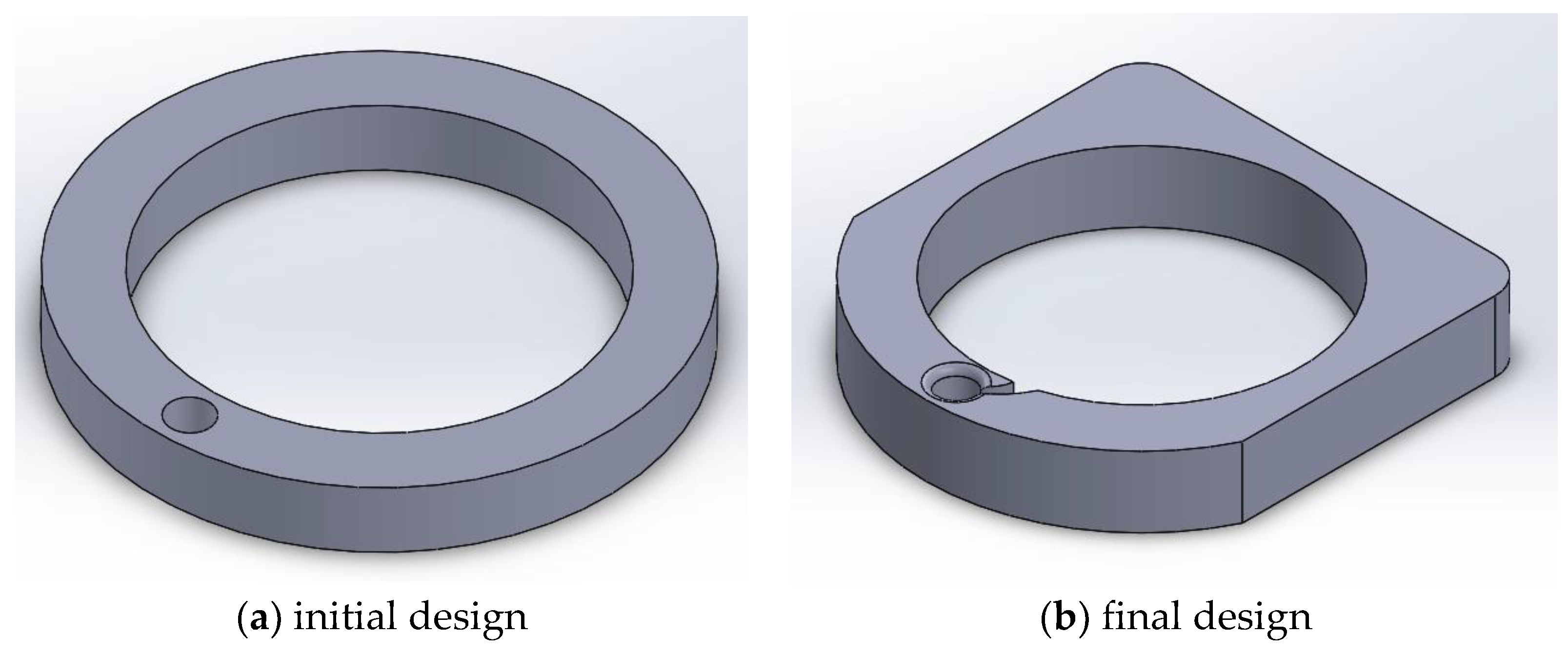
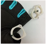
The pinch enhancer used a servo and cable combination to apply tension force onto the fingers that assist in enabling a stronger and more stable pinch. The user is required to put on a three-piece set of PLA-made rings that attaches the cables onto their fingers. The final design was first presented in the previous section and is the product of a Finite Element Analysis (FEA) method used to optimise and ensure the safety and suitability of its shape and size. Figure 9 exhibits the initial and final design of the enhancer rings.
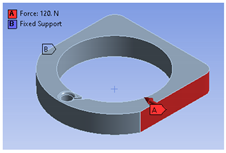
The static analysis was carried out in three different loading conditions to simulate the real-world applications. The first condition was the external load caused by the compressive force of the fingers (see Figure 10). The purpose of this analysis was to test if the design fails under extreme loads during component handling. This test intended to simulate compression caused by finger pinching actions as shown below. This analysis was carried out under different conditions due to the various orientations about the centre axis.
Pinch force was obtained through various literature studies. Mathiowetz, et al. [55] and Mohammadian, et al. [56] found that men between the ages of 60 to 64 years have an average palmar pinch force of 98 N and 96 N respectively. On the other hand, Nilsen, et al. [57] found that the force was lower (63 N) for men between the ages of 60 to 69 years. Lastly, on the other extreme, men who regularly deal with heavy manual work above the age of 60 years were found to possess an average palmar pinch force of 120 N [58]. Therefore, for this experiment, a pinch force of 120 N was used. The boundary conditions used are:
  • Axial load of 120 N acting across a single surface of the ring.
  • Fixed support at the outer surface opposite of the axial load.
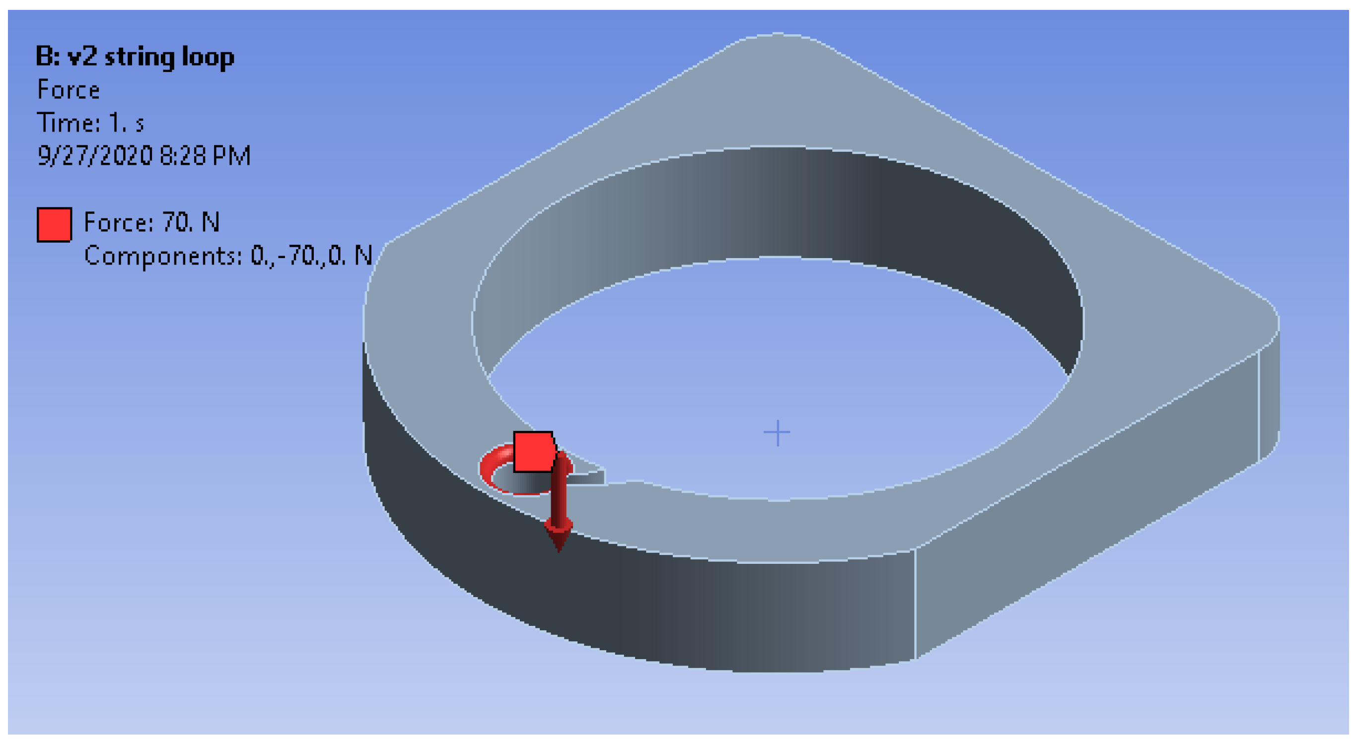
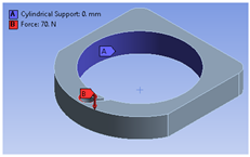
The second condition would be the analysis of force around the cable loop (see Figure 11). The servo motors will produce torque to rotate and hold the fingers into position through the force transfer of the cables. This section was considered critical due to the constant tension force experienced by the PLA rings. The magnitude of the tension force applied on the cable loop was estimated to be 70 N, calculated from the maximum stall torque of the servo motor. The boundary conditions used are:
  • Axial load of 70 N acting around the edge of the string loop.
  • Fixed cylindrical support at the inner surface of the finger loop.
The final FEA condition was to simulate the actual pinching action while using the device. This condition was a combination of 120 N pinch force exerted by the fingers and 70 N tension force from the servo cables. The boundary conditions used were:
  • Axial load of 70 N acting around the edge of the string loop.
  • Axial load of 120 N acting across a single surface of the ring.
  • Fixed cylindrical support at the inner surface of the finger loop.
In the FEA for the initial design, it was found that the component structure was incapable of withstanding the applied stress thus causing it to fail. The complete analysis is revealed in the data availability sheet.
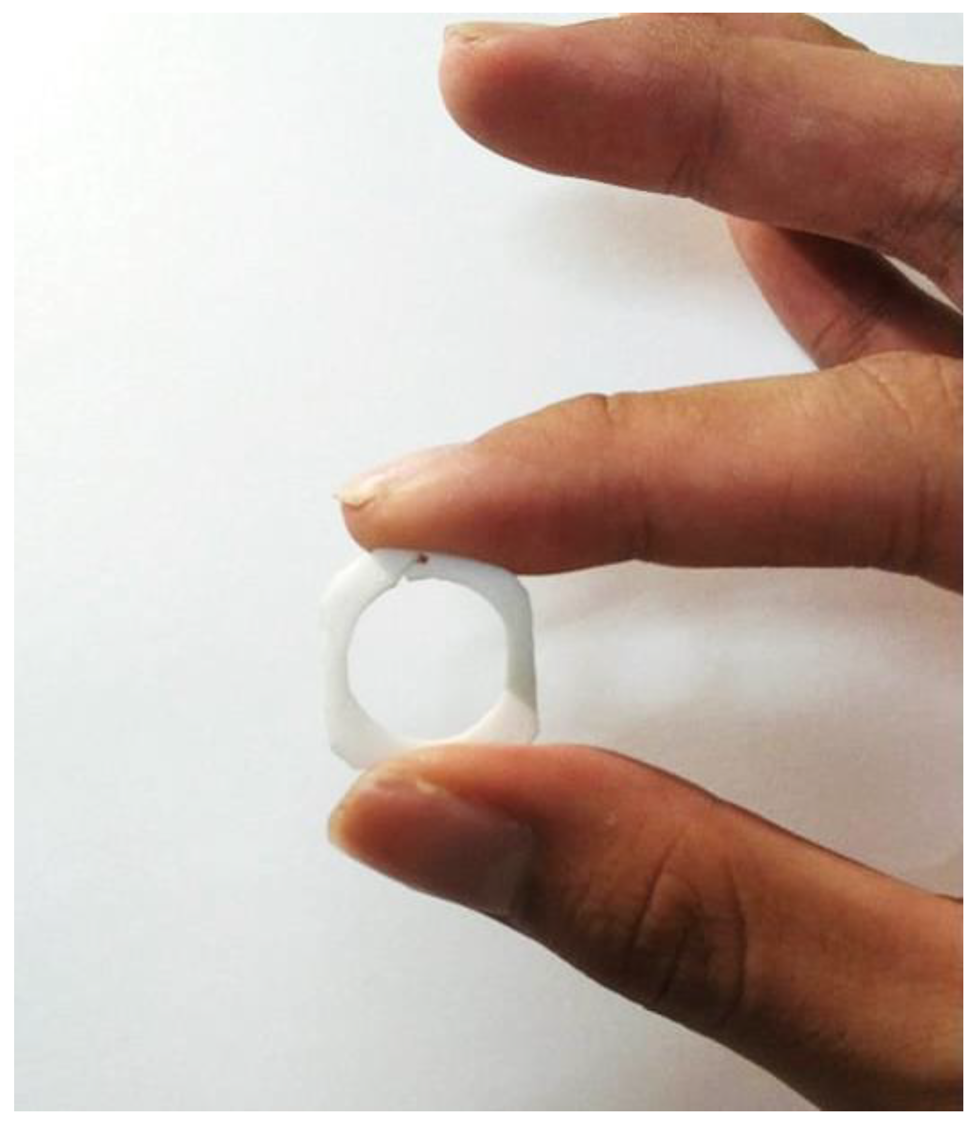
The overall shape of the finger ring was modified from a circular ring into a squarish shape (see Figure 12). Increasing the volume of an object would increase its sturdiness and resistance to stresses and strain. This motive was achieved by increasing the height and changing the shape from a simple circle into a more complex shape.
The final design allowed for a narrower profile, reducing the outer length from 24 mm to 22 mm, which made the ring less encumbering. Furthermore, additional material was added to the four corners of the item, increasing the maximum wall thickness up to 5.73 mm. As shown in detail (A), a 0.4 mm fillet was added to the cable loop which increased stress distribution. Additionally, a curved slot was designed to allow for easy attachment and detachment of the finger rings depending on the user’s finger size. The curved design prevented the tendon cables from escaping the loop during a normal application.
Table 10 compares the major differences before and after modifications. The design changes showed improved characteristics on all areas except in weight. The finger ring increased in weight by 42% though an object weighing one gram was still acceptable on the fingers as a typical gold ring weighs about 100 g.

3.2.2. FEA Results of Final Design

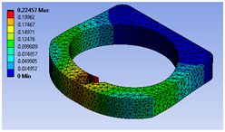
The final design iteration used for the prototype was also tested using the FEA method. The boundary conditions and test results are tabulated in Table 11. For tests 1a and 1b, the boundary condition of 120 N force was applied on the surface with a fixed support on the opposite surface. The displacement contour and stress profile under the condition of test 1a yielded a maximum deformation of 0.225 mm and maximum stress at 28.649 MPa while for 1b, the values were 0.303 mm and 36.113 MPa respectively. Both tests 1a and 1b did not exceed the ultimate tensile stress limit of 41 MPa under these loadings.
Test 2 was designed to analyse the tension force of the tendon cable that reacts on the area of the string loop. The maximum von Mises stress that it experienced was 35.997 MPa which is less than 41 MPa (ultimate tensile strength). The maximum deformation was 0.027 mm. The design modification of adding a fillet around the loop increased the ability of the component to withstand stress from the tendon cables.
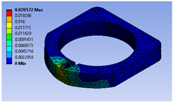
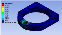
Test 3 on the other hand was a combination of test 1a and test 2. The displacement contours and stress profiles of the final finger ring design during a simulated pinch action (test 3) are also presented. The maximum displacement was 0.0206 mm while the maximum von Mises stress was 36.031 MPa.
The final simulation result is tabulated in Table 12. The improved design fulfilled the static analysis requirement of experiencing forces below the tensile limit.

3.3. Usability Experiment

Usability in this study was measured by the device’s ability to produce a statistically positive outcome when elderly people pinch everyday objects while using it. The experiment design is discussed in this section.

3.3.1. Pinch Force Hypotheses

Null Hypothesis H0.
There is no significant difference in the mean pinch force of elderly people with and without the use of the pinch enhancer.
Alternative Hypothesis H1.
There is a significant difference in the mean pinch force of elderly people with and without the use of the pinch enhancer.

3.3.2. Pinch Force Steadiness Hypotheses

Null Hypothesis H0.
There is no significant difference in the pinch force steadiness of elderly people with and without the use of the pinch enhancer.
Alternative Hypothesis H1.
There is a significant difference in the pinch force steadiness of elderly people with and without the use of the pinch enhancer.

3.3.3. Experimental Method

A quasi-experiment aims to evaluate causation between an intervention and an outcome without randomisation [59,60]. This design method is prominent in medical informatics literature [61] and in studies of infectious diseases [59]. A counterbalanced design is a higher-order quasi-experiment design whereby every participant receives all the same interventions but in a random order [62]. This counterbalanced quasi-experiment method was chosen in this study as it is able to control participant variables while obtaining statistical significance at a smaller sample size [63].
In the present study, participants were required to pinch and hold six different household objects using the pulp pinch. In their effort to study challenges faced by elderly people in their homes, Fausset, et al. [64] developed seven sub-categories of tasks which included cleaning, outdoor, home upkeep, repair, indoor update remodelling and movement within the home. Among those selections, cleaning, outdoor and home upkeep were found to be the most challenging activities for the elderly people.
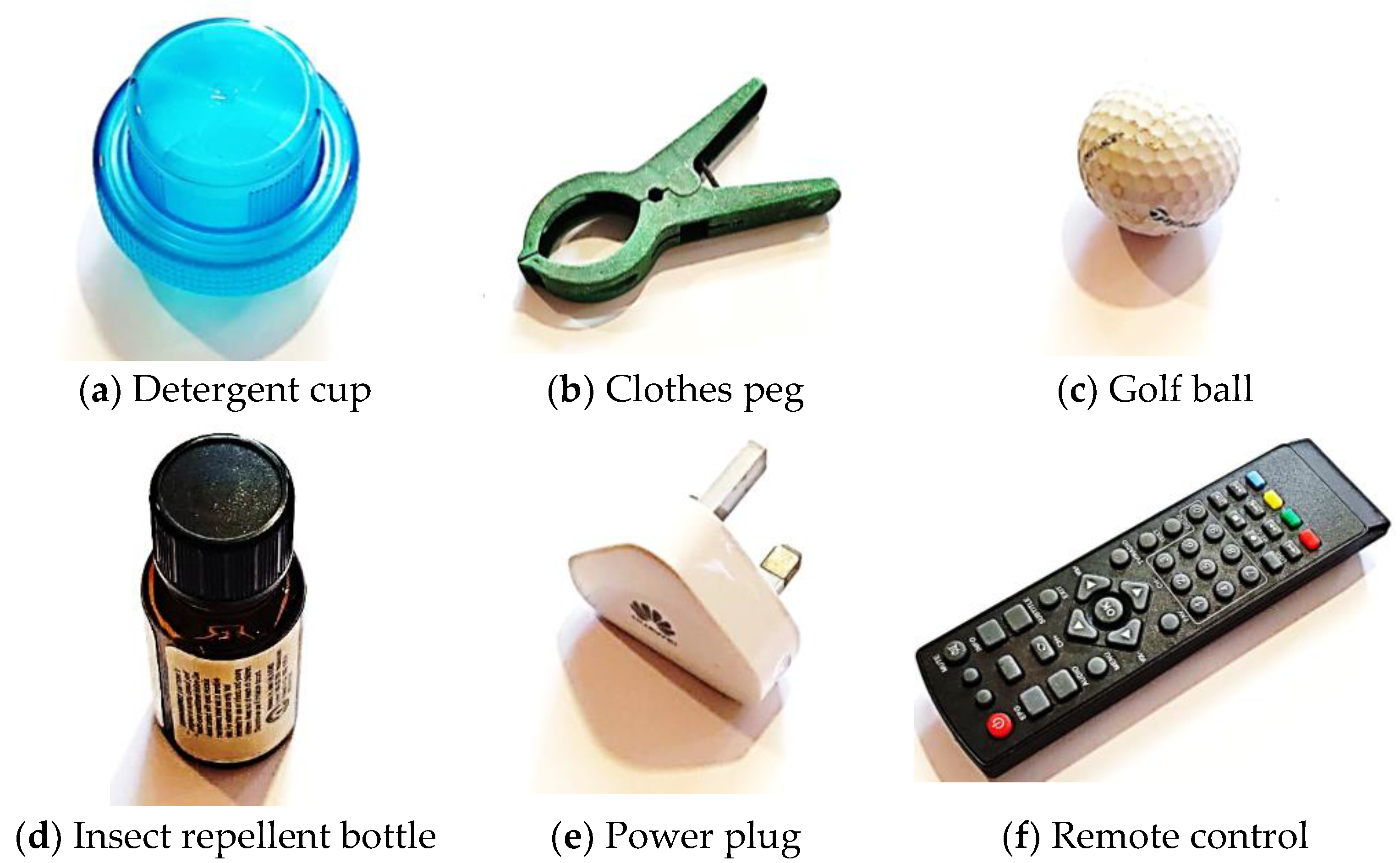
Based on these three categories, two everyday items commonly used by the elderly people are selected for each category. The six items included a detergent cup and clothes peg representing cleaning activities, a golf ball and insect repellent for the outdoor category, and a power plug and remote control for the home upkeep (see Figure 13). Smaby, et al. [65] conducted a similar experiment testing lateral pinch on six items including using a key, inserting and removing a plug from an outlet, using a zipper, pushing a television remote button, stabbing food with a fork and inserting an automated teller machine card.

3.3.4. Population

The procedures of this study were submitted to the Technology Transfer Office of the Multimedia University, and a research ethics approval was granted by the research ethics committee on 13 July 2020 with the approval reference number EA0052020. Upon approval, the study was conducted at various homes of elderly individuals in Johor Bahru, Johor, Malaysia.
The research recruited 11 healthy elderly people above the age of 60 years (65.27 ± 5.76) consisting of five males and seven females. The test was not administrated to subjects who did not fulfil the general health criteria and who had prior injuries on the hands or fingers. These exclusion criteria were referenced from several research studies with a similar experimental aim of studying finger pinching abilities [55,58,66].
A non-probability sampling method was chosen for this qualitative study as the goal was not to describe a broad population [67]. The criterion-i strategy was used to identify and select all cases that fulfil a predetermined set of criteria [68]. The exclusion criteria included (a) experiencing acute pain in the right hand and fingers or having any form of hand-related injuries, (b) having medical conditions such as high blood pressure, post-stroke conditions or have been hospitalised during the last six months, and (c) unable to live an active lifestyle. All participating subjects voluntarily declared themselves to be healthy and able to live an active lifestyle independently. Participants were asked to report their age and gender through a consent form.

3.3.5. Equipment

The Tekscan® Flexiforce A201 sensor (Tekscan, Inc., Massachusetts, USA) is a force sensing resistor that reduces resistance when force is applied. It is a flexible, ultra-thin printer circuit that is only 0.208 mm in thickness. These advantages allow the flexiforce sensors to be integrated with objects of different shapes and sizes for pinch force measurements in this study which would otherwise be impossible with a traditional Jamar dynamometer. According to Werle, et al. [69], elderly people were found to have a higher standard deviation of pinch force when compared to younger people. They suggested that this difference was partially influenced by the characteristics of the pinch gauge which had a step scale of 0.5 kg. As the strength value of elderly people decreases, the force difference expressed in standard deviation in percent increases due to the low sensitivity of the measuring device. The Flexiforce sensor has the advantage of measuring forces up to 0.01 g [70]. Figure 14 shows the calibration of the pressure sensor using fixed calibrated weights of 50 g, 100 g, and 200 g.

3.3.6. Experiment Validity

For each pinch test, subjects were seated with their shoulder adducted and neutrally rotated, elbow flexed to 90˚ and their forearm and wrist in a neutral position (see Figure 15) [71]. A neutral wrist position was found to exert higher pinch force compared to extension or flexion positions [72]. These guidelines comply with the recommendations of the American Society of Hand Therapists (ASHT) for upper extremity and body position during grip strength measurements.
Each participant was given one warm-up trial to familiarise themselves with all six objects. Participants were then to proceed with pinching and lifting the six items for ten seconds, alternating between with and without using the device. A 30s recovery period was allocated between the sets. According to previous research [58,69,73,74], a 15 s rest was found to be sufficient. Trossman and Li [75] found no significant difference between the grip strength of participants who had 15, 30 or 60 s of recovery periods. However, the subjects in this particular study were between 19 to 41 years of age. Since the subjects of the present study were elderly people, it was reasonable to allocate a longer rest period of 30 s.

3.3.7. Procedures

Before the start of each action, participants would position their fingers with the Flexiforce sensor between their thumb and the object (see Figure 16). Once they were ready, the researcher would say “start” and participants would pinch the object firmly and lift it about 10 cm off the table, with their wrist leaving the table. The researcher would then say “hold” for the cue to sustain the pinch force and position for 10 s. During this 10 s, subjects were required to pinch the objects naturally as they would during everyday applications. After 10 s, the “stop” command would signal subjects to place the object back on the table, thus completing one measurement. Each measurement was then saved in an Excel spreadsheet for further analysis. After completing all six objects both without and with the device twice, participants were thanked for their contribution.

3.3.8. Experimental Analysis

The collected data was processed using inferential statistics from the Minitab 18 software. The parametric paired t-test was used to analyse the data for each pinch object experiment with a p-value of 0.05 to determine statistical significance. Besides that, support analysis was also conducted on the collected data. These support analyses included a priori power analysis to ensure that there is sufficient power in the data apart from sample size estimation, and normality test to check if the data was normally distributed before proceeding to the t-test.
Power in statistics refers to the number of tests that participants needed to avoid a type II error which is a false negative result. In designing a study, the a priori power analysis was used to ensure that the number of recruited test participants had adequate power, though over-testing was discouraged as it is a waste of time and resources [76]. The researchers decided to use the power analysis as a priori test to decide on the required sample size.
In the power analysis calculation of the pilot study, the power was normally set at 0.80 (80% statistical power) which is often the recommended value [77]. The Cohen’s d for the paired t-test was calculated with Equation (8) [78].
Cohen s   d z = M diff S p
From the equation, Mdiff is the mean difference between the two groups and Sp is the pooled standard deviation.

4. Results and Discussion

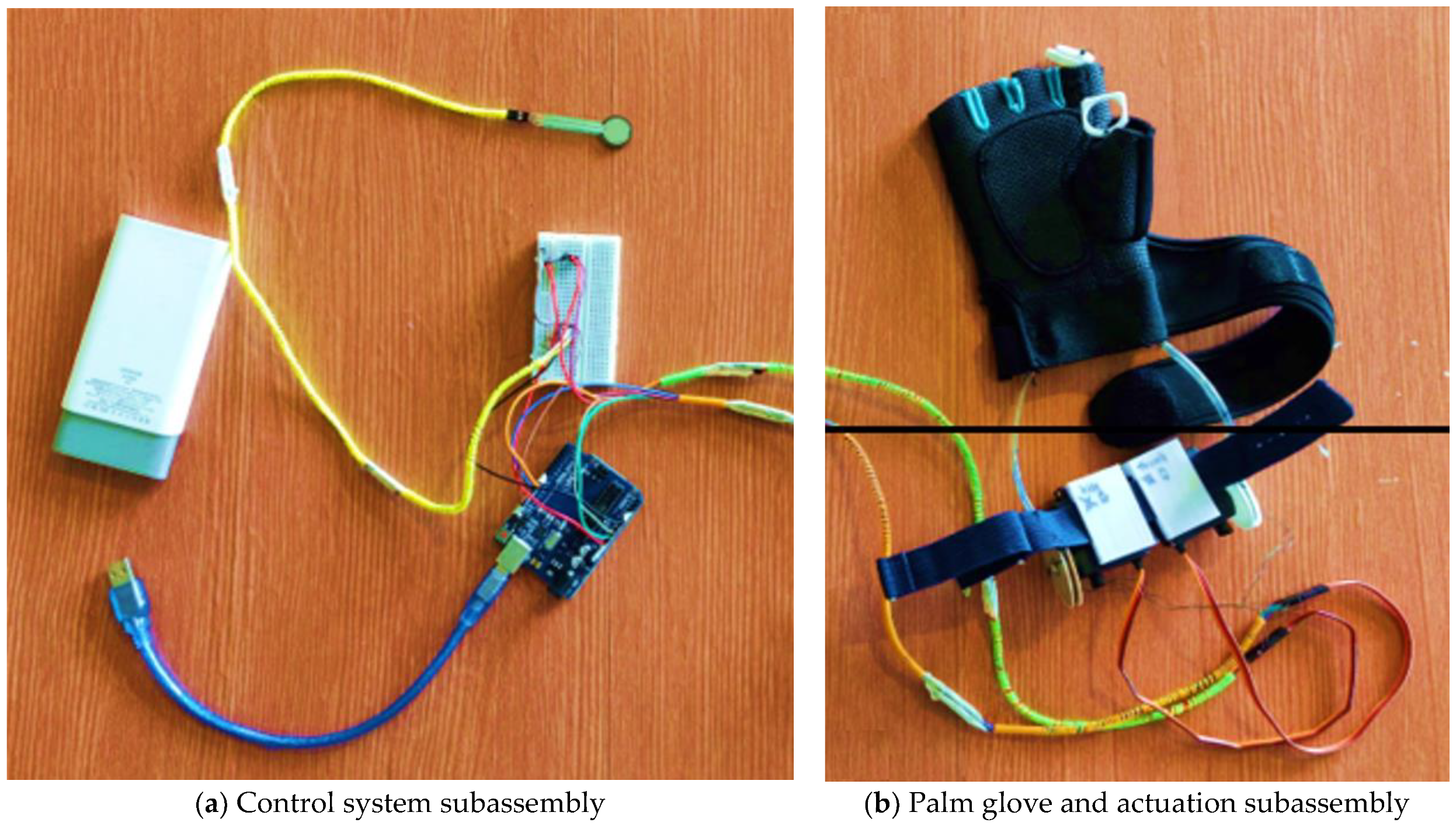
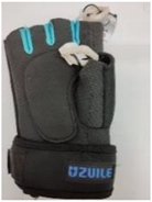
Figure 17 shows the final device assembly with its different subassemblies. The device’s main parts are the glove component, actuator system and control system. The whole assistant device was powered by a 10,000 mAh power bank (Zhongshan Pineng Battery Co., Ltd., Guangdong, China) which enables portability. A description of how each component contributes to the overall device is shown in Table 13.
Table 14 highlights some performance details of the pinch assistant device. The total weight of the device prototype (excluding the power bank) was 320 g. This number represents the total amount of added weight on the users’ hand while operating the device. This device was designed to facilitate three flexion DOFs (DIP, PIP, MCP) for the index finger and two flexion DOFs (IP, MCP) for the thumb. Both bending angles of the thumb and index finger were tuned to the fingers’ range of motion but could be adjusted both mechanically and in the control programme.

4.1. Experimental Results

4.1.1. Power Analysis

Table 15 shows the a priori power analysis test results for all six test objects. The predicted sample sizes in the table are recommended for the statistical results to have a Type II error of only 20% probability or lower. The analysis also verifies that there is only a 5% change or less for a Type I error to occur. The power analysis of the pilot study suggests that at least seven samples should be collected to ensure sufficient statistical power (actual power = 0.91).
A total of 11 subjects between the ages of 60 to 70 years participated in the study, comprising of five males and seven female elderlies. This participation is a 50% increase from the seven participants estimated in the pilot study. The test was not conducted on subjects who did not fulfil the general health criteria and who had prior injuries on their hands or fingers. All subjects voluntarily declared themselves to be healthy and able to live an active lifestyle independently.

4.1.2. Normality Test

A t-test is a parametric test that assumes that the difference between the pairs is normally distributed. A normality test is done for each pair of datasets. The Ryan-Joiner test of normality (similar to the Shapiro-Wilk test) was selected because it was found to be more powerful with smaller sample sizes when compared with other tests such as the Anderson-Darling and Kolmogorov-Smirnov test [79,80]. The null hypothesis is that the collected data does not significantly differ from a normal distribution. In order to accept the null hypothesis, the p-value must be larger or equal to 0.05 as shown in Table 16. All other assumptions for using the paired t-test to determine the difference between the pinch force measured with and without using the pinch assistant were also met.

4.1.3. Pinch Force

Table 17 shows the paired mean and standard deviations of the pinch force measured during the t-test. The mean force exerted using the pinch device is recorded to be larger across all six tests. The t-test is conducted using a p-value of 0.05 for all statistical tests.
The pinch force generated together with the pinch assistive device is found to be significantly higher than the one generated without the device. The significant differences are found in Test 1 [t(10) = t-statistic, p < 0.001], Test 2 [t(10) = t-statistic, p < 0.001], Test 3 [t(10) = t-statistic, p = 0.001], Test 4 [t(10) = t-statistic, p = 0.001], Test 5 [t(10) = t-statistic, p = 0.004], and Test 6 [t(10) = t-statistic, p < 0.001]. The paired difference result for the pinch force is recorded in Table 18. The null hypothesis is rejected while the alternative hypothesis is accepted. Hence, there is a significant difference in the mean pinch force of elderly people with and without the use of the pinch enhancer.
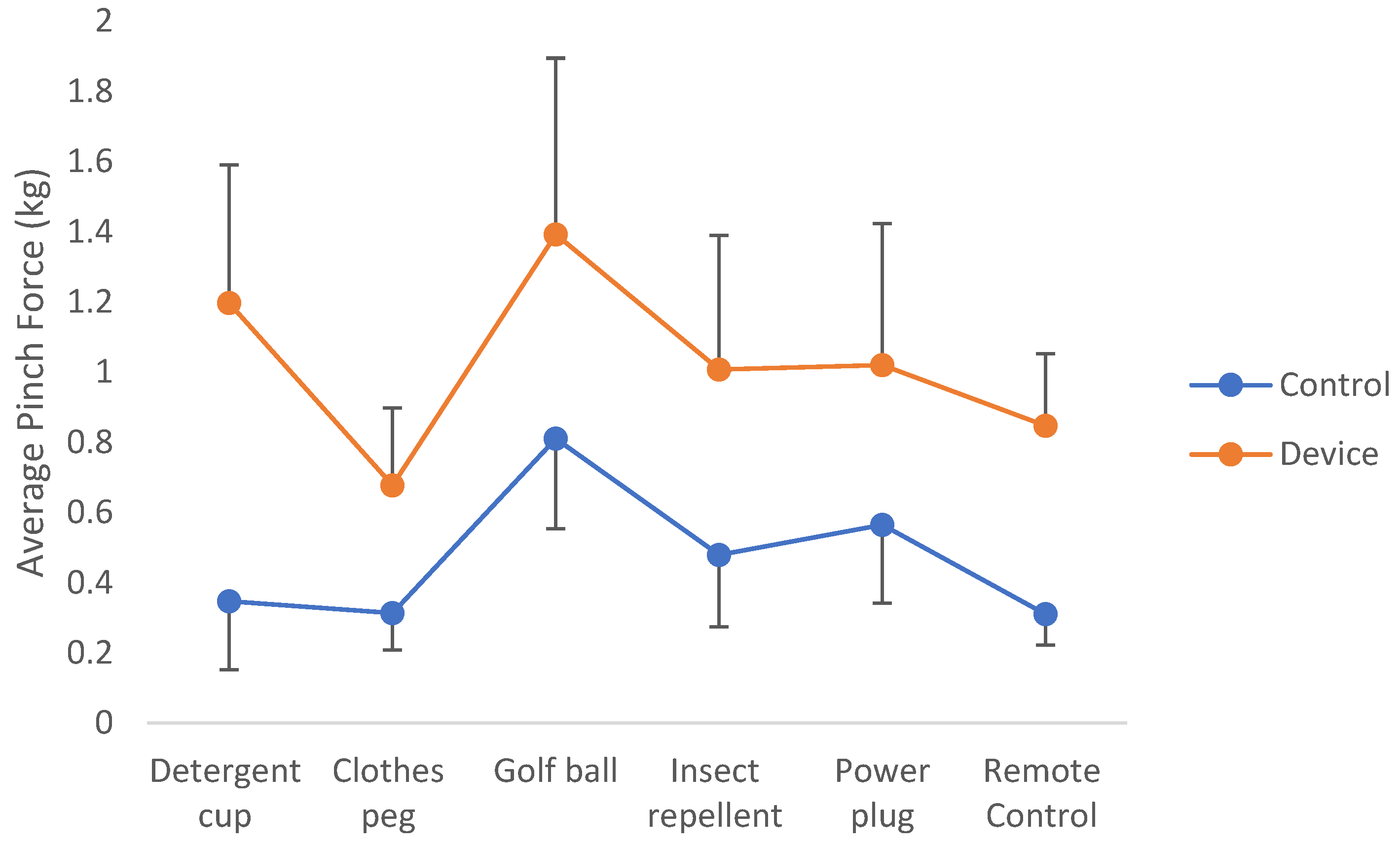
Figure 18 compares the force measured while the pinch test is conducted on all six test objects with and without the assistance of the pinch device. The average pinch force graph profile of the six test objects has a similar trend between the control set and the results obtained while using the pinch device. The golf ball pinch test is found to be the highest in both sets of tests while the clothes peg and remote-control tests have the two lowest average pinch forces. On the other hand, the detergent cup is found to produce the highest percentage of increase in average pinch force (more than 200%) with the help of the pinch enhancer.
The combination of p-values and effect sizes concludes that the use of this finger pinch enhancer has a statistically significant outcome on the user’s pinch force and also indicates that the magnitude of the difference between the control and experimental pinch force is large. Results from the pinch force test indicate a significant increase in pinch force after using the pinch assistive device to pick up all six day-to-day objects. The device is hence considered able to assist the elderly people in applying a higher amount of pressure on those common everyday items.
This assisted increase in force during pinching activities can act as a reinforcement for the naturally exerted finger force. Given that elderly people often naturally exert a higher grip force [81] and pinch force [82,83] compared to younger people due to the slippery and insecure grip caused by changes in skin properties, this device would be useful in increasing the safety margin of their pinch force. With this device, elderly people would enjoy the benefits of a stronger pinch without overexerting themselves.
Although such an excess force might be considered as wasted energy, it might still be necessary in order to help elderly people pinch more effectively and safely. There are several changes in the elderly body that could explain the need for this excessive force during pinching. Firstly, when compared to younger subjects, elderly people were less capable of intentionally resetting neuro-synergistic reflexes while having excessive and random firing motor neurons to reach the same force output [84]. With the Thenar muscles being the most active muscles in grasping activities, reduced strength and range of thumb abduction could reduce the finger dexterity of elderly people [85]. Moreover, old people often have a diminished anticipatory build-up in pinch force even when perturbations (changes in load) are expected [86]. These factors could be possible reasons why elderly people typically use a probing strategy that lacks a smooth ramp in force during pinches. The inability to quickly control their finger force in response to changes would suggest the need for a device that actively provides pressure, thus creating a stronger and steadier pinch.
The sudden spike in pinch force after using the pinch assistive device during the detergent cup test and the inconsistent graph profile between both sets of tests suggests some irregularity caused by the unfamiliarity with the device. This slight aberration is commonly preventable once the users have enough practice with the assistive device as suggested by past studies [87,88].

4.1.4. Pinch Force Steadiness

Figure 19 illustrates the pinch force performance of one of the participants during the clothes peg pinch test before and after using the pinch enhancer. From this comparison, after using the device, the subject produced better pinch abilities in both force (maximum) and steadiness (standard deviation).
With the utilisation of the pinch enhancer, results of pinch force steadiness show significant improvements. Table 19 compares the mean and standard deviation of both the control results and results while using the device. The steadiness of pinch force is quantified by calculating the standard deviation of the force profile while sustaining the pinch for 10 s.
From Table 20, results of pinch force steadiness while receiving assistance from the device decreased significantly across all six test objects. The significant differences were found in Test 1 [t(10) = t-statistic, p = 0.004], Test 2 [t(10) = t-statistic, p = 0.004], Test 3 [t(10) = t-statistic, p = 0.005], Test 4 [t(10) = t-statistic, p = 0.018], Test 5 [t(10) = t-statistic, p = 0.007], and Test 6 [t(10) = t-statistic, p = 0.019]. The null hypothesis is rejected while the alternative hypothesis is accepted. Hence, there is a significant difference in pinch force steadiness of elderly people with and without the use of the pinch enhancer.
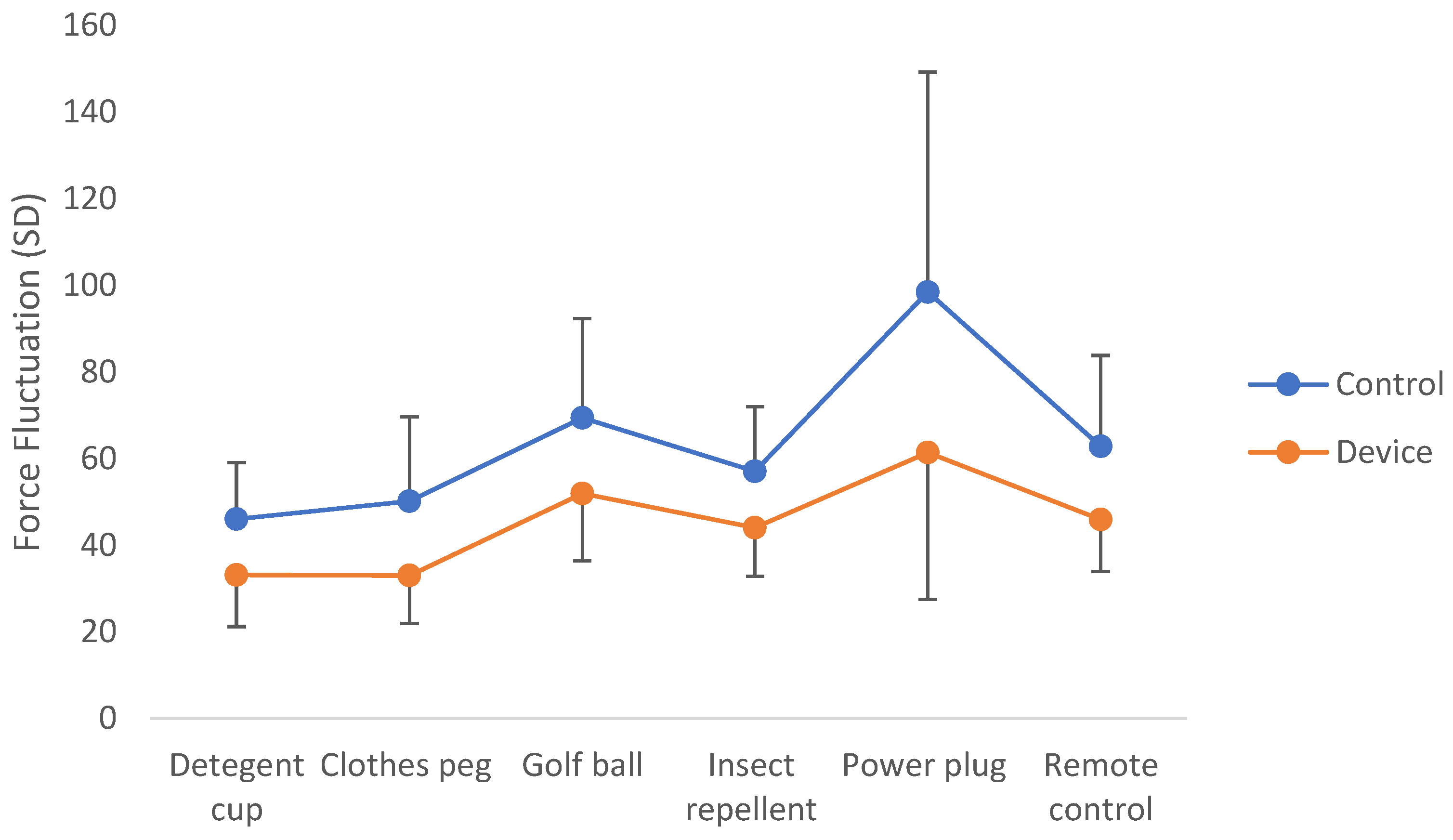
Figure 20 illustrates the pinch force steadiness before and after using the device. Similar to the pinch force experiment, the graph profile between each device (before and after assistance) has a similar pattern. Across all six objects, the utilisation of the device can reduce the standard deviation of the pinch force, which infers that a steadier pinch grip is produced after using the device.
It was found that after using the device, the elderly people exerted a pinch force with a lower standard deviation, indicating a more stable pinch grip. The force steadiness graph for all six objects had a similar profile with and without the use of the device, indicating a uniform pattern that is not object-dependent. Cole and Rotella [89], De Serres and Fang [82], and Kinoshita and Francis [81] all found that elderly people have a large fluctuation in their precision grip force rate curve which also indicates a lower force control capacity. With the help of a pinch assistant such as the one in this study, they will have the ability to reduce the force fluctuation which would enable them to pinch with a steadier grip.

4.2. T-Test Results Comparison

Table 21 and Table 22 compare the improvements measured in the current study with findings from other researchers who have applied other intervention methods mainly through exercises. Due to the disparities in key research methods, a direct comparison might not be possible. However, an indirect comparison could provide some level of justification between this novel pinch assistive device and other more traditional methods of improving pinch abilities.
The referenced studies [8] recorded the improvements in pinch abilities after subjects underwent a training task of holding two metal balls in the palm and rotating them clockwise and counterclockwise. The training frequency included two 10-min sessions each day, 6 days a week for 8 weeks. It was tested on elderly people between 65–79 years of age. In contrast to the current study’s findings, these exercises have led to significant improvements in pinch force but not in pinch force steadiness.
In another study, elderly people between the ages of 59 and 74 years participated in a 12-week strength training programme with three training sessions per week as the intervention method [90]. To test for pinch force and pinch steadiness, a portable device that restrained the hand while permitting load variance in accordance with the needs of the subjects was used. The present study showed a significant increase in pinch force and pinch force steadiness after training. Therefore, it can be somewhat affirmed that the improvements in pinching abilities seen in the usage of the current study’s device are akin to results obtained by someone who has undergone a strength training regime.

4.3. Prototype Design Discussion

The pinch assistant is compared with several research devices in terms of its control, actuation, and safety. The unique simplicity of the device actuation can be seen in its single tendon cable used to control finger flexion. With just one cable running along each finger at the front of the palm, this simplifies the structure of the device, as well as allows more user flexibility with a half glove design. The PLA finger rings attached at each of the finger joints act as pivot points of the cables and allow the device to assist the fingers while not obstructing finger mobility.

4.3.1. Device Control

The current study’s device included a straightforward single-path control trigger where the actuators activate only when a certain force threshold is exceeded. The pros and cons of this method can be seen when compared with other devices such as the one developed by Hasegawa, et al. [91] which had a bioelectric potential-based switching control that switches between two algorithms for finger-following control and grasping force control. The device used its finger-following control mode during the pinching of small objects that do not require exoskeleton support and switched to grasping force control when the user activated a power grasp. While a two-stage control allowed for better movement control, it is actually a necessary function for the device to differentiate between a power grasp and a finger pinch to avoid restraining the user’s finger movements. Such a function was not required in the current study’s device due to its flexible structure which allowed the hands to move freely.
However, one area of improvement in the prototype control would be the integration of more sensitive sensors. Currently, the user must activate the device using their left hand. With force sensors at the fingertips, for instance, Nilsson, et al. [92] developed an assistive device that was able to recognise the moment a user begins to grasp an object and calculate the amount of force required for the activity.

4.3.2. Device Actuation

A successful design of a finger exoskeleton largely depends on its ability to kinematically control the movement of fingers through the control of their joints. The device by Hasegawa, Mikami, Watanabe and Sankai [91] is a device with eight degrees of freedom (DOFs) that requires eight DC motors. Using one motor for each joint, allows for better control of finger flexion and extension.
In the current design, one motor was used to control the thumb (two DOFs) and another was used for the index finger (three DOFs). This method is analogous to how a finger pinch works as it was found that most of the actuation force during a pulp pinch, tip pinch and grasp motion is transmitted through a single flexor digitorum profundus tendon [93]. Furthermore, each motor can be tuned to suit flexion of various degrees which defers with the pinch prehension type. This condition was still sufficient for control because the objective of the device was only to assist in pinching action.
With the fingers being such complex systems with many ROMs and DOFs, an exoskeleton must compliment the finger movements as naturally as possible. With this understanding in mind, soft robotics and tendon cables that actuate fingers have the advantage over mechanical linkage designs. The hand exoskeleton (HX) is a two-finger exoskeleton device with a similar concept but with four and three active DOFs for the thumb and index finger respectively [16]. The additional two DOFs as compared to the current design were required to facilitate finger abduction/adduction. This comparison between the HX design and the current device illustrates the limitation of using linkages although it does allow for better position control.

4.3.3. Safety

Elderly people are prone to injuries which makes user safety a priority in the device design. The current study’s device has a ROM similar to that of a human’s finger joint. The servo motors are placed away from the finger and attached to the forearm. These conditions are safety benefits similar to that of soft robotic assistive devices like the SEM Glove. These devices excel in being lightweight, easy to use and safe for the fingers but at the cost of lower finger strength support [92].
Another benefit to using the tendon actuator mechanism includes the ability for customisation and easy adjustments for joint ROM. The UoA hand exoskeleton is an important device that uses pneumatic and electric actuators to control the fingers. It is a device for the whole hand with 19 DOFs and has the ability to control 81% of the overall ROM of the hand [94]. However, this advantage is still restricted by limitations in the mechanical joints. In contrast, a tendon cable actuator system, such as the one used in the current study, can be adjusted to achieve a larger ROM by using the appropriate gear transmission.
When compared with the earlier mentioned devices that use mechanical serial link manipulation to move the fingers, the current study’s design has the advantage of improved ROM, lightweight attributes and a customisable design. The soft robotic glove by Polygerinos, Wang, Galloway, Wood and Walsh [21] has more control over finger movements compared with the current design though this control was achieved through a custom-made composite tubular construction reinforced by fibre walls which require a 3.3 kg belt pack around the waist to provide hydraulic pressure. The current study’s device on the other hand weighs only about 520 g.
Safety systems were set in place to protect the individual’s hand. With reference to the ROM of each finger joint as stated in the previous chapters, software limits were used to limit the servo position which prevented excessive joint rotation as also seen in an exoskeleton design by Worsnopp, Peshkin, Colgate and Kamper [37]. Besides that, the servos were mechanically limited to a maximum of 180° which presented the second level of safety for the user.

4.4. Device Comparison

Smaby, et al. [95] conducted a study to measure the average pinch force needed for ADL which included opening and closing zippers, inserting and removing a key, using a remote control button and others. Most of these actions required less than 10.5 N of force except for inserting and removing a plug and closing a large zipper which required between 15 to 30 N. The pinch force of the current study’s device during the pinch action was measured at 13.9 N which is sufficient for most daily pinching activities.
Table 23 compares the current study’s device with two other research devices and two commercial exoskeleton devices with regard to weight, number of DOFs, number of actuators and pinch force exerted. It is crucial to note that there are some disparities in the experiments done on the other devices. Hence, it may only be possible to use their findings as an indirect reference.
Before using the device, the average pinch force of the elderly people was measured to be between 3.1 to 8.1 N. This lower pinch force could be partly due to the weak strength of the elderly test participants or due to the different shapes and sizes of the objects. The pinch assistant was able to increase that force to a region that is closer to the average pinch force generated from the other exoskeleton devices (see Figure 21). The force-to-weight ratio was used to compare the device performance as it fairly considered the output force with respect to the device weight. The current study’s device has a ratio of 0.0248 N/g which outperformed both commercial devices, namely the Bebionic (0.0231 N/g) and I-limb (0.13 N/g) [96]. Although the current study’s device has a higher force output as compared with the X-Limb, the X-Limb has a higher force-to-weight ratio at 0.0403 N/g, as found in the comparison with the SoftHand (0.0384 N/g) [97].
Takahashi, et al. [98] developed a soft exoskeleton glove with the ability to generatedexterous finger joint movement with little constraints. By using the penumatic artificial muscles, postural control of the joints (up to 20 DOFs) was enabled with a fingertip force of 8 N. The soft exoskeleton design has the benefit of flexibility but a generally lower output force of 8 N compared to the proposed invention of this study (13.9 N). The pneumatic system used by the authors also requires an air compressor unit which reduces user mobility, unlike mechanical designs which do not.
Finger exoskeletal devices are frequently measured by their force output and deflection angles [18,19,97]. The conventional method of obtaining device force would be with the use of a stationary load cell which measures the pressure exerted by the device. By using several day-to-day objects during the usability test, this study presents another dimension to the obtained results. The shape and size of an object can significantly affect how the elderly person pinches it [76]. During the golf ball experiment, it was found that elderly people pinched with a greater force (both with and without using the device) when compared to the force produced on the other objects. That being said, the device was still able to significantly improve the users’ pinch both in strength and stability. Thus, the usability test coupled with statistical results indicated that the device significantly improves the strength and stability of elderly users while pinching common daily household items.

4.5. Novelty and Industrial Applicability

The novelty of the device is in its design which stems from the specific goal of assisting elderly people to pinch better. This goal allowed for a streamlined design process to solve the problem of pinch weakness first before extending it to other areas of hand functions such as three- or four-finger pinch and power grip. Together with the underactuated mechanism, additive manufacturing technology and off-the-shelf electronic components, a working prototype was created for the testing and proof of concept.
As observed from the t-test results, the device has applicational value for elderly people in their day-to-day pinching activities. A significant improvement in pinch force and pinch force steadiness would allow them to have a better overall pinch ability. Furthermore, the inexpensive production cost of each device would widen its accessibility to the public. Independent living elderly people would also be able to use the device due to its easy-to-use design that does not require extra assistance.

5. Conclusions

The main purpose of this study was to extend the development of a concept from previous research by designing and developing a finger grip enhancer that facilitates the day-to-day pinching activities of elderly people. In order to achieve this aim, a finger exoskeleton assistive design from a previous study was analysed using an FEA simulation to validate the device’s safety and usability aspects. A working prototype capable of producing a max force of 13.9 N and a force-to-weight ratio of 0.0248 N/g was produced. The usability validation was done through an experiment that measured the exerted force and the force steadiness of elderly people when pinching everyday household objects. Overall, the t-test indicated that there were significant improvements (p < 0.05) in the elderly people’s pinch abilities after using the proposed invention.

5.1. Contribution of Study

With elderly people experiencing functional limitations in performing activities of daily living, this device is an attempt to assist elderly people in pinching better. The approach taken was a streamlined design process to solve the problem of pinch weakness first before extending it to other areas of hand functions such as three- or four-finger pinch and power grip. Together with the underactuated mechanism, additive manufacturing technology and off-the-shelf electronic components, a working prototype was created for the testing and proof of concept.
As observed from the t-test results, the device has applicational value for elderly people in their day-to-day pinching activities. A significant improvement in pinch force and pinch force steadiness would allow them to have a better overall pinch ability. Furthermore, the inexpensive production cost of each device would widen its accessibility to the public. Independent living elderly people would also be able to use the device due to its easy-to-use design that does not require extra assistance.

5.2. Limitations of Research

There were several limitations identified in this study. Firstly, the usability of the device was only measured in pinch force and pinch force steadiness. In order to account for dynamic pinches in daily tasks more effectively, it would have been better to measure both force magnitude and directional control (dexterity). Therefore, finger dexterity could be another measurable which determines the effectiveness of the device.
Although usability tests were performed, there was a lack of formal feedback from the elderly users. Furthermore, while this study accounted for various mechanical design analyses, it lacked the analyses on anatomical aspects such as finger joint biomechanics and fingertip trajectory, which could have been done to verify the risk of injuries to the users.
Besides that, another limitation was found in the test procedures. When participants pinched and lifted objects using submaximal force, some inconsistencies in the results could have occurred when the assistive device was used. These inconsistencies were mainly due to the participants’ unfamiliarity with using the device, which might have caused participants to pinch harder than required. In order to overcome this limitation, the participants would require more practice with the device over a longer time period.
The validity experiment uses a purposive sampling method which is not meant to represent an entire population but rather selectively engage participants that would benefit from this device. Elderly participants who fulfilled the predefined criteria could participant in the experiment. With the statistical support of the power analysis, the number of samples was found to be sufficient. However, the increase in sample size would generally improve the results by providing a more accurate mean value, smaller margin of error, and identifying outliers. Unfortunately, these benefits come at the cost of time and money which are limited resources.

5.3. Research Challenges

Throughout the testing process, the participants generally did not experience much discomfort. The palm gloves and finger rings were designed to fit most hand sizes and did not produce additional stress on the hand. That being said, the device assembly on the user’s wrist is heavy and might lead to long-term complications. The two servo motors should be reduced before the device can truly be used for day-to-day activities. The reason for this challenge is due to the researcher’s decision to use off-the-shelf components such as servo motors, a power supply, and a control board. This convenience came at the cost of heavier and bulkier components.
Furthermore, the device uses tension in the tendon cables to assist with pinch activities. Unlike some innovations that use pneumatic flexible soft robotics, the tendon cables, though strong, can strain the fingers if not properly controlled. Although the mechanism is only activated when the user initiates a pinch, pinching multiple items over an extended period of time might stress the finger joints. The tension of the cables, although closely mimicking finger tendons, presents additional challenges. With the cables running on the palm, the user’s ease of movement is limited when picking up an item. If the control mechanism were to be fitted behind the hand, the device could then wrap over the fingers for a smoother control during flexion and extension of the finger joints.

5.4. Recommendation for Future Research

Based on the research outcomes and limitations of this study, some directions for future research are suggested. With regard to the device, more movement-perceptive sensors such as Electromyography (EMG) sensors could be used for motor activation. This approach would allow the system to detect the electrical signal produced by the hand muscles. EMG sensors were also used in exoskeleton devices in other areas such as a hip-assisted exoskeleton for semi-squat lifting [99]. EMG sensors were used to measure muscle activation so that the output torque can change in an adaptive manner according to the angular velocity of the wearer’s joint. Furthermore, it would also be of interest to account for finger extension in the pinch assistive device although the extension of fingers can be accomplished by the users themselves. With the ability to manipulate both extension and flexion, the device control would be able to adjust the fingers to external perturbation, allowing the finger pinch to adapt naturally. The device is also limited to elderlies who have a certain degree of finger mobility. In the future, modifications in the device to accommodate hand dysfunctions from post-stroke patients would be beneficial.
The Purdue Pegboard Test and the Jebsen-Taylor Hand Function Test are recognised methods for testing manual dexterity and motor function. These tests were initially excluded from this study as they were considered to be secondary hand-eye or reach-to-grasp tests that are prone to adaptive strategies. However, with the understanding that the body is a complete system, tests involving the entire upper extremity would allow for a more holistic view of the improvements made in pinch abilities through the device.
The test analysis could be extended to a broader category of people, which can shed insights on how different people react to an assistive device such as the one in this study. Since conditions such as sarcopenia and carpal tunnel syndrome are fairly common among elderly people, further testing among these patients is encouraged. Testing the device with a younger population would also allow for more comparisons to be made with the elderly. This suggestion would serve as a benchmark or controlled study for improvements made by the device. Tests among the younger population would also open possibilities of developing an assistive device for manual workers such as factory packers that heavily rely on repeated precision pinching.
Incorporating the present invention with therapies based on virtual reality could be another way to improve elderly people’s motor functions in the upper limb, though the most optimal treatment approaches, ideal duration, and intensity of the intervention still remains unclear [100]. Lastly, the invention can be integrated into therapies based on neuroplasticity and motor (re)learning through game-based rehabilitation, which involves intense, repeated, and task-based training for upper limb function improvement [101].

Author Contributions

Conceptualization, D.W.H.T., P.K.N., C.C.H. and Y.J.N.; Data curation, D.W.H.T.; Formal analysis, D.W.H.T. and P.K.N.; Funding acquisition, P.K.N.; Investigation, D.W.H.T., P.K.N., A.S., C.C.H. and Y.J.N.; Methodology, D.W.H.T., P.K.N. and A.S.; Project administration, P.K.N. and E.E.M.N.; Resources, P.K.N. and E.E.M.N.; Supervision, P.K.N. and E.E.M.N.; Validation, D.W.H.T. and C.C.H.; Visualization, A.S.; Writing—original draft, D.W.H.T. and P.K.N.; Writing—review & editing, P.K.N., E.E.M.N., A.S., C.C.H. and Y.J.N. All authors have read and agreed to the published version of the manuscript.

Funding

The article processing charge for this manuscript is supported by Multimedia University (Reference ID: MMU/RMC/PC/2021/53612).

Institutional Review Board Statement

The study was conducted according to the guidelines of the Declaration of Helsinki. All participants gave their written informed consent prior to the experiments. All procedures and protocols have been approved by the Research Ethics Committee (REC) from the Technology Transfer Office (TTO) of Multimedia University. The research ethics approval for the project has been granted with the approval number EA0052020, and the approval letter has been endorsed by the TTO Director cum REC Secretariat of the university.

Informed Consent Statement

Informed consent was obtained from all subjects involved in the study.

Data Availability Statement

This project contains the following underlying data: Data Availability Sheet.docx (facts, comparisons, preliminary results, data and discussions). The data can be found at Figshare: https://doi.org/10.6084/m9.figshare.15027975. Data are available under the terms of the Creative Commons Attribution 4.0 International license (CC-BY 4.0).

Acknowledgments

This research article is in partial fulfilment of the requirements for the Master of Engineering Science degree at the Faculty of Engineering and Technology, Multimedia University (MMU), Malaysia. The researchers sincerely thank the faculty and university for their support in allowing this research to be carried out. The researchers also thank the Technology Transfer Office of MMU for granting the public disclosure approval for this paper. Special thanks go to Chiew Fen Ng for her constructive criticism of the manuscript.

Conflicts of Interest

The authors declare no conflict of interest.

References

  1. Gul, R.; Alam, I.; Ibrar, A.; Saleem, K.; Pervez, I.P. Aging Affects the Number of WBC and Its Subsets in A Pakistani Cohort of Young and Elderly Women. ARPN J. Eng. Appl. Sci. 2013, 8, 638–641. [Google Scholar]
  2. Kurnianingsih, K.; Nugroho, L.; Widyawan, W.; Lazuardi, L. Reflective Sensing and Conditioning System in Ubiquitous Home Care for Elderly People. ARPN J. Eng. Appl. Sci. 2015, 10, 998–1007. [Google Scholar]
  3. Seidler, R.; Bernard, J.; B Burutolu, T.; Fling, B.; Gordon, M.; Gwin, J.; Kwak, Y.; Lipps, D. Motor Control and Aging: Links to Age-Related Brain Structural, Functional, and Biochemical Effects. Neurosci. Biobehav. Rev. 2009, 34, 721–733. [Google Scholar] [CrossRef] [Green Version]
  4. Young Hoogendam, Y.; van der Lijn, F.; Vernooij, M.W.; Hofman, A.; Niessen, W.J.; Lugt, A.; Arfan Ikram, M.; van der Geest, J.N. Older Age Relates to Worsening of Fine Motor Skills: A Population-Based Study of Middle-Aged and Elderly Persons. Front. Aging Neurosci. 2014, 6, 259. [Google Scholar] [CrossRef]
  5. Rahman, N.; Thomas, J.J.; Rice, M.S. The Relationship between Hand Strength and the Forces Used to Access Containers by Well Elderly Persons. Am. J. Occup. Ther. 2002, 56, 78–85. [Google Scholar] [CrossRef] [Green Version]
  6. Rice, M.S.; Leonard, C.; Carter, M. Grip strengths and required forces in accessing everyday containers in a normal population. Am. J. Occup. Ther. 1998, 52, 621–626. [Google Scholar] [CrossRef] [Green Version]
  7. Chen, X.P.; Lu, Y.M.; Zhang, J. Intervention study of finger-movement exercises and finger weight-lift training for improvement of handgrip strength among the very elderly. Int. J. Nurs. Sci. 2014, 1, 165–170. [Google Scholar] [CrossRef] [Green Version]
  8. Ranganathan, V.K.; Siemionow, V.; Sahgal, V.; Liu, J.Z.; Yue, G.H. Skilled Finger Movement Exercise Improves Hand Function. J. Gerontol. Ser. A 2001, 56, 518–522. [Google Scholar] [CrossRef]
  9. Ellegaard, K.; von Bülow, C.; Røpke, A.; Bartholdy, C.; Hansen, I.S.; Rifbjerg-Madsen, S.; Henriksen, M.; Wæhrens, E.E. Hand exercise for women with rheumatoid arthritis and decreased hand function: An exploratory randomized controlled trial. Arthritis Res. Ther. 2019, 21, 158. [Google Scholar] [CrossRef] [Green Version]
  10. Rodríguez-Sánchez-Laulhé, P.; Luque-Romero, L.G.; Blanquero, J.; Suero-Pineda, A.; Biscarri-Carbonero, Á.; Barrero-García, F.J.; Heredia-Rizo, A.M. A mobile app using therapeutic exercise and education for self-management in patients with hand rheumatoid arthritis: A randomized controlled trial protocol. Trials 2020, 21, 777. [Google Scholar] [CrossRef]
  11. Liu, B.; Chen, X.; Li, Y.; Liu, H.; Guo, S.; Yu, P. Effect of passive finger exercises on grip strength and the ability to perform activities of daily living for older people with dementia: A 12-week randomized controlled trial. Clin. Interv. Aging 2018, 13, 2169–2177. [Google Scholar] [CrossRef] [Green Version]
  12. Cole, T.; Robinson, L.; Romero, L.; O’Brien, L. Effectiveness of interventions to improve therapy adherence in people with upper limb conditions: A systematic review. J. Hand Ther. Off. J. Am. Soc. Hand Ther. 2019, 32, 175–183.e7. [Google Scholar] [CrossRef]
  13. Hepple, R.T.; Rice, C.L. Innervation and neuromuscular control in ageing skeletal muscle. J. Physiol. 2016, 594, 1965–1978. [Google Scholar] [CrossRef] [PubMed]
  14. Rahim, A.A.; Patar, M.N.A.A.; Amin, A.M.; Mahmud, J. The Development of Finger Rehabilitation Device for Stroke Patients. Appl. Mech. Mater. 2013, 393, 604–610. [Google Scholar] [CrossRef]
  15. Rahman, M.A.; Al-Jumaily, A. Design and Development of a Hand Exoskeleton for Rehabilitation Following Stroke. Procedia Eng. 2012, 41, 1028–1034. [Google Scholar] [CrossRef] [Green Version]
  16. Cempini, M.; De Rossi, S.M.M.; Lenzi, T.; Cortese, M.; Giovacchini, F.; Vitiello, N.; Carrozza, M.C. Kinematics and design of a portable and wearable exoskeleton for hand rehabilitation. In Proceedings of the 2013 IEEE 13th International Conference on Rehabilitation Robotics (ICORR), Seattle, WA, USA, 24–26 June 2013; pp. 1–6. [Google Scholar] [CrossRef]
  17. Zaid, A.; Tee, C.C.; Sukor, J.A.; Hanafi, D. Development of hand exoskeleton for rehabilitation of post-stroke patient. AIP Conf. Proc. 2017, 1891, 020103. [Google Scholar] [CrossRef] [Green Version]
  18. Rudd, G.; Daly, L.; Jovanovic, V.; Cuckov, F. A Low-Cost Soft Robotic Hand Exoskeleton for Use in Therapy of Limited Hand–Motor Function. Appl. Sci. 2019, 9, 3751. [Google Scholar] [CrossRef] [Green Version]
  19. Wege, A.; Hommel, G. Development and Control of A Hand Exoskeleton for Rehabilitation of Hand Injuries. In Proceedings of the 2005 IEEE/RSJ International Conference on Intelligent Robots and Systems, Edmonton, AB, Canada, 2–6 August 2005; pp. 3046–3051. [Google Scholar]
  20. In, H.; Cho, K.-J.; Kim, K.; Lee, B. Jointless structure and under-actuation mechanism for compact hand exoskeleton. In Proceedings of the 2011 IEEE International Conference on Rehabilitation Robotics, Zurich, Switzerland, 29 June–1 July 2011; Volume 2011, pp. 1–6. [Google Scholar]
  21. Polygerinos, P.; Wang, Z.; Galloway, K.C.; Wood, R.J.; Walsh, C.J. Soft robotic glove for combined assistance and at-home rehabilitation. Robot. Auton. Syst. 2015, 73, 135–143. [Google Scholar] [CrossRef] [Green Version]
  22. DiCicco, M.; Lucas, L.; Matsuoka, Y. Comparison of Control Strategies for an EMG Controlled Orthotic Exoskeleton for the Hand. In Proceedings of the IEEE International Conference on Robotics and Automation 2004, New Orleans, LA, USA, 26 April–1 May 2004; pp. 1622–1627. [Google Scholar] [CrossRef]
  23. Hasegawa, Y.; Mikami, Y.; Watanabe, K.; Firouzimehr, Z.; Sankai, Y. Wearable Handling Support System for Paralyzed Patient. In Proceedings of the 2008 IEEE/RSJ International Conference on Intelligent Robots and Systems, Nice, France, 22–26 September 2008; pp. 741–746. [Google Scholar] [CrossRef]
  24. Mahmud, N.A.; Yoep, N.; Paiwai, F.; Shahein, N.A.; Tan, M.P.; Yusof, M.; Muhamad, N.A. Functional Limitations and Falls. In National Health and Morbidity Survey 2018: Elderly Health; Chan, Y.Y., Tan, L., Ahmad, F.H., Yusoff, M.F.M., Lodz, N.A., Shawal, N., Sooryanarayana, R., Aris, T., Robert, T., Saminathan, T.A., Eds.; Institute for Public Health, National Institutes of Health (NIH), Ministry of Health: Selangor, Malaysia, 2018; Volume 2, pp. 8–13. [Google Scholar]
  25. Tan, D.; Ng, P.; Noor, E. A TRIZ-driven conceptualisation of finger grip enhancer designs for the elderly [version 1; peer review: 1 approved, 1 approved with reservations]. F1000Research 2021, 10, 392. [Google Scholar] [CrossRef]
  26. Garrett, J.W. The adult human hand: Some anthropometric and biomechanical considerations. Hum. Factors 1971, 13, 117–131. [Google Scholar] [CrossRef] [PubMed]
  27. Greiner, T.M. Hand Anthropometry of US Army Personnel; Army Natick Reseach Development and Engineering Center: Natick, MA, USA, 1991. [Google Scholar]
  28. Taylor, C.L.; Schwarz, R.J. The anatomy and mechanics of the human hand. Artif. Limbs 1955, 2, 22–35. [Google Scholar]
  29. Duncan, S.F.M.; Saracevic, C.E.; Kakinoki, R. Biomechanics of the Hand. Hand Clin. 2013, 29, 483–492. [Google Scholar] [CrossRef]
  30. Lin, J.; Wu, Y.; Huang, T.S. Modeling the constraints of human hand motion. Proc. Workshop Hum. Motion 2000, 121–126. [Google Scholar] [CrossRef] [Green Version]
  31. Sarac, M.; Solazzi, M.; Frisoli, A. Design Requirements of Generic Hand Exoskeletons and Survey of Hand Exoskeletons for Rehabilitation, Assistive or Haptic Use. IEEE Trans. Haptics 2019, 12, 400–413. [Google Scholar] [CrossRef] [Green Version]
  32. Tanaka, T.; Amadio, P.C.; Zhao, C.; Zobitz, M.E.; An, K.-N. Flexor digitorum profundus tendon tension during finger manipulation. J. Hand Ther. 2005, 18, 330–338. [Google Scholar] [CrossRef] [Green Version]
  33. ElKoura, G.; Singh, K. Handrix: Animating the human hand. In Proceedings of the 2003 ACM SIGGRAPH/Eurographics Symposium on Computer Animation, San Diego, CA, USA, 26–27 July 2003; pp. 110–119. [Google Scholar] [CrossRef]
  34. Lisini, T.; Scheggi, S.; Meli, L.; Mohammadi, M.; Prattichizzo, D. GESTO: A Glove for Enhanced Sensing and Touching Based on Inertial and Magnetic Sensors for Hand Tracking and Cutaneous Feedback. IEEE Trans. Hum.-Mach. Syst. 2017, 47, 1066–1076. [Google Scholar] [CrossRef]
  35. Lince, A.R. A Portable Assistive Rehabilitation Hand Exoskeleton. Ph.D. Thesis, Polytechnic University of Turin, Turin, Italy, 2016. [Google Scholar]
  36. Imrhan, S.N. The influence of wrist position on different types of pinch strength. Appl. Ergon. 1991, 22, 379–384. [Google Scholar] [CrossRef]
  37. Worsnopp, T.T.; Peshkin, M.; Colgate, J.; Kamper, D. An Actuated Finger Exoskeleton for Hand Rehabilitation Following Stroke. In Proceedings of the 2007 IEEE 10th International Conference on Rehabilitation Robotics, Noordwijk, The Netherlands, 13–15 June 2007; pp. 896–901. [Google Scholar] [CrossRef] [Green Version]
  38. Leonardis, D.; Barsotti, M.; Loconsole, C.; Solazzi, M.; Troncossi, M.; Mazzotti, C.; Castelli, V.P.; Procopio, C.; Lamola, G.; Chisari, C.; et al. An EMG-Controlled Robotic Hand Exoskeleton for Bilateral Rehabilitation. IEEE Trans Haptics 2015, 8, 140–151. [Google Scholar] [CrossRef]
  39. Alexander, B.; Kotiuk, V. Proportions of Hand Segments. Int. J. Morphol. 2010, 28, 755–758. [Google Scholar]
  40. Richterman, I.E.; DuPree, J.; Thoder, J.; Kozin, S.H. The radiographic analysis of web height. J. Hand Surg. 1998, 23, 1071–1076. [Google Scholar] [CrossRef]
  41. Hume, M.; Gellman, H.; McKellop, H.; Brumfield, R. Functional range of motion of the joints of the hand. J. Hand Surg. 1990, 15, 240–243. [Google Scholar] [CrossRef]
  42. Jahn, J.; Janes, W.E.; Saheb-Al-Zamani, M.; Burbank, C.M.; Brown, J.M.; Engsberg, J.R. Identification of three movement phases of the hand during lateral and pulp pinches using video motion capture. Hand 2013, 8, 123–131. [Google Scholar] [CrossRef] [PubMed] [Green Version]
  43. Brorsson, S. Biomechanical Studies of Finger Extension Function. Analysis with a New Force Measuring Device and Ultrasound Examination in Rheumatoid Arthritis and Healhty Muscles. Ph.D. Thesis, University of Gothenburg, Gothenburg, Sweden, 2008. [Google Scholar]
  44. Shojaei Barjuei, E.; Caldwell, D.G.; Ortiz, J. Bond Graph Modeling and Kalman Filter Observer Design for an Industrial Back-Support Exoskeleton. Designs 2020, 4, 53. [Google Scholar] [CrossRef]
  45. Lampman, S.; Dieter, G.E. ASM Handbook: Materials Selection and Design; Taylor & Francis: Abingdon, UK, 1997; Volume 20. [Google Scholar]
  46. Novakova-Marcincinova, L.; Novak-Marcincin, J.; Barna, J.; Torok, J. Special Materials Used in FDM Rapid Prototyping Technology Application. In Proceedings of the 2012 IEEE 16th International Conference on Intelligent Engineering Systems (INES), Lisbon, Portugal, 13–15 June 2012; pp. 73–76. [Google Scholar] [CrossRef]
  47. McKeen, L. Elastomers. In The Effect of Sterilization Methods on Plastics and Elastomers, 4th ed.; McKeen, L., Ed.; William Andrew Publishing: Norwich, NY, USA, 2018; pp. 305–351. [Google Scholar]
  48. Kulkarni, G.S. Introduction to Polymer and Their Recycling Techniques. In Recycling of Polyurethane Foams; Thomas, S., Rane, A.V., Kanny, K., V.K, A., Thomas, M.G., Eds.; William Andrew Publishing: Norwich, NY, USA, 2018; pp. 1–16. [Google Scholar]
  49. Materialise. 3D Printing Materials. Available online: https://bit.ly/3o4HM03 (accessed on 27 March 2020).
  50. Camargo, J.; Machado, A.; Almeida, E.; Moura, E. Mechanical properties of PLA-graphene filament for FDM 3D printing. Int. J. Adv. Manuf. Technol. 2019, 103, 2423–2443. [Google Scholar] [CrossRef]
  51. Rodriguez-Panes, A.; Claver, J.; Camacho, A.M. The Influence of Manufacturing Parameters on the Mechanical Behaviour of PLA and ABS Pieces Manufactured by FDM: A Comparative Analysis. Materials 2018, 11, 1333. [Google Scholar] [CrossRef] [Green Version]
  52. MatWeb. Overview of Materials for Polylactic Acid (PLA) Biopolymer. Available online: https://bit.ly/2KTcbQy (accessed on 27 March 2020).
  53. Stratasys. Nylon (Polyamide) Parts on Demand. Available online: https://www.stratasysdirect.com/materials/thermoplastics/nylon#nylon-12 (accessed on 27 March 2020).
  54. Hyie, K.; Budin, S.; Martinus, N.; Salleh, Z.; Masdek, N. Tensile and flexural investigation on polypropylene recycling. J. Phys. Conf. Ser. 2019, 1174, 012005. [Google Scholar] [CrossRef]
  55. Mathiowetz, V.; Kashman, N.; Volland, G.; Weber, K.; Dowe, M.; Rogers, S. Grip and Pinch Strength: Normative data for adults. Arch. Phys. Med. Rehabil. 1985, 66, 69–74. [Google Scholar]
  56. Mohammadian, M.; Choobineh, A.; Haghdoost, A.; Hasheminejad, N. Normative data of grip and pinch strengths in healthy adults of Iranian population. Iran J. Public Health 2014, 43, 1113–1122. [Google Scholar]
  57. Nilsen, T.; Hermann, M.; Eriksen, C.; Dagfinrud, H.; Mowinckel, P.; Kjeken, I. Grip force and pinch grip in an adult population: Reference values and factors associated with grip force. Scand. J. Occup. Ther. 2011, 19, 288–296. [Google Scholar] [CrossRef]
  58. Harth, A.; Vetter, W.R. Grip and pinch strength among selected adult occupational groups. Occup. Ther. Int. 1994, 1, 13–28. [Google Scholar] [CrossRef]
  59. Eliopoulos, G.M.; Harris, A.D.; Bradham, D.D.; Baumgarten, M.; Zuckerman, I.H.; Fink, J.C.; Perencevich, E.N. The Use and Interpretation of Quasi-Experimental Studies in Infectious Diseases. Clin. Infect. Dis. 2004, 38, 1586–1591. [Google Scholar] [CrossRef] [Green Version]
  60. Maciejewski, M.L. Quasi-experimental design. Biostat. Epidemiol. 2020, 4, 38–47. [Google Scholar] [CrossRef]
  61. Harris, A.D.; McGregor, J.C.; Perencevich, E.N.; Furuno, J.P.; Zhu, J.; Peterson, D.E.; Finkelstein, J. The use and interpretation of quasi-experimental studies in medical informatics. J. Am. Med Inform. Assoc. 2006, 13, 16–23. [Google Scholar] [CrossRef] [PubMed]
  62. Campbell, D.T.; Stanley, J.C. Experimental and Quasi-Experimental Designs for Research; Ravenio Books: Cambridge, UK, 2015. [Google Scholar]
  63. Walukonis, K.; Beasley, J.; Boerema, R.; Powers, J.; Anderson, K. The impact of finger position on pinch strength. Hand Ther. 2018, 23, 70–76. [Google Scholar] [CrossRef] [Green Version]
  64. Fausset, C.; Kelly, A.; Rogers, W.; Fisk, A. Challenges to Aging in Place: Understanding Home Maintenance Difficulties. J. Hous. Elder. 2011, 25, 125–141. [Google Scholar] [CrossRef] [PubMed] [Green Version]
  65. Smaby, N.; Baker, B.; Johanson, M.E.; Towles, J.D.; Murray, W.M. Determination of lateral pinch force requirements for six common activities of daily living. In Proceedings of the Third National Meeting for Rehabilitation Research and Development Conference, Arlington, VA, USA, 10–12 February 2002; p. 104. [Google Scholar]
  66. Stegink Jansen, C.W.; Simper, V.K.; Stuart, H.G., Jr.; Pinkerton, H.M. Measurement of maximum voluntary pinch strength: Effects of forearm position and outcome score. J. Hand Ther. 2003, 16, 326–336. [Google Scholar] [CrossRef] [Green Version]
  67. Ames, H.; Glenton, C.; Lewin, S. Purposive sampling in a qualitative evidence synthesis: A worked example from a synthesis on parental perceptions of vaccination communication. BMC Med. Res. Methodol. 2019, 19, 26. [Google Scholar] [CrossRef]
  68. Palinkas, L.A.; Horwitz, S.M.; Green, C.A.; Wisdom, J.P.; Duan, N.; Hoagwood, K. Purposeful Sampling for Qualitative Data Collection and Analysis in Mixed Method Implementation Research. Adm. Policy Ment. Health 2015, 42, 533–544. [Google Scholar] [CrossRef] [Green Version]
  69. Werle, S.; Goldhahn, J.; Drerup, S.; Simmen, B.R.; Sprott, H.; Herren, D.B. Age- and Gender-Specific Normative Data of Grip and Pinch Strength in a Healthy Adult Swiss Population. J. Hand Surg. 2009, 34, 76–84. [Google Scholar] [CrossRef]
  70. Parmar, S.; Khodasevych, I.; Troynikov, O. Evaluation of Flexible Force Sensors for Pressure Monitoring in Treatment of Chronic Venous Disorders. Sensors 2017, 17, 1923. [Google Scholar] [CrossRef]
  71. Mathiowetz, V.; Weber, K.; Volland, G.; Kashman, N. Reliability and validity of grip and pinch strength evaluations. J. Hand Surg. 1984, 9, 222–226. [Google Scholar] [CrossRef]
  72. Shih, Y.-C.; Ou, Y.-C. Influences of span and wrist posture on peak chuck pinch strength and time needed to reach peak strength. Int. J. Ind. Ergon. 2005, 35, 527–536. [Google Scholar] [CrossRef]
  73. Hanten, W.P.; Chen, W.-Y.; Austin, A.A.; Brooks, R.E.; Carter, H.C.; Law, C.A.; Morgan, M.K.; Sanders, D.J.; Swan, C.A.; Vanderslice, A.L. Maximum grip strength in normal subjects from 20 to 64 years of age. J. Hand Ther. 1999, 12, 193–200. [Google Scholar] [CrossRef]
  74. Mathiowetz, V. Effects of three trials on grip and pinch strength measurements. J. Hand Ther. 1990, 3, 195–198. [Google Scholar] [CrossRef]
  75. Trossman, P.B.; Li, P.-W. The Effect of the Duration of Intertrial Rest Periods on Isometric Grip Strength Performance in Young Adults. Occup. Ther. J. Res. 1989, 9, 362–378. [Google Scholar] [CrossRef]
  76. Jones, S.R.; Carley, S.; Harrison, M. An introduction to power and sample size estimation. Emerg. Med. J. 2003, 20, 453–458. [Google Scholar] [CrossRef] [PubMed]
  77. Brysbaert, M. How Many Participants Do We Have to Include in Properly Powered Experiments? A Tutorial of Power Analysis with Reference Tables. J. Cogn. 2019, 2, 16. [Google Scholar] [CrossRef] [PubMed]
  78. Lakens, D. Calculating and reporting effect sizes to facilitate cumulative science: A practical primer for t-tests and ANOVAs. Front. Psychol. 2013, 4, 863. [Google Scholar] [CrossRef] [Green Version]
  79. Ghasemi, A.; Zahediasl, S. Normality tests for statistical analysis: A guide for non-statisticians. Int. J. Endocrinol. Metab. 2012, 10, 486–489. [Google Scholar] [CrossRef] [Green Version]
  80. Nosakhare, U.H.; Bright, A.F. Evaluation of Techniques for Univariate Normality Test Using Monte Carlo Simulation. Am. J. Theor. Appl. Stat. 2018, 6, 51–61. [Google Scholar]
  81. Kinoshita, H.; Francis, P.R. A comparison of prehension force control in young and elderly individuals. Eur. J. Appl. Physiol. Occup. Physiol. 1996, 74, 450–460. [Google Scholar] [CrossRef]
  82. De Serres, S.J.; Fang, N.Z. The accuracy of perception of a pinch grip force in older adults. Can. J. Physiol. Pharmacol. 2004, 82, 693–701. [Google Scholar] [CrossRef]
  83. Spirduso, W.W.; Choi, J. Age and Practice Effects on Force Control of the Thumb and Index Fingers in Precision Pinching and Bilateral Coordination. In Sensorimotor Impairment in the Elderly; Stelmach, G.E., Hömberg, V., Eds.; Springer: Dordrecht, The Netherlands, 1993; pp. 393–412. [Google Scholar]
  84. Stelmach, G.E.; Hömberg, V. Sensorimotor Impairment in the Elderly; Springer: Heidelberg, Germany, 2012. [Google Scholar]
  85. Boatright, J.R.; Kiebzak, G.M.; O’Neil, D.M.; Peindl, R.D. Measurement of thumb abduction strength: Normative data and a comparison with grip and pinch strength. J. Hand Surg. 1997, 22, 843–848. [Google Scholar] [CrossRef]
  86. Carmeli, E.; Patish, H.; Coleman, R. The Aging Hand. J. Gerontol. Ser. A 2003, 58, 146–152. [Google Scholar] [CrossRef] [Green Version]
  87. Kornatz, K.W.; Christou, E.A.; Enoka, R.M. Practice reduces motor unit discharge variability in a hand muscle and improves manual dexterity in old adults. J. Appl. Physiol. 2005, 98, 2072–2080. [Google Scholar] [CrossRef]
  88. Portnoy, S.; Halaby, O.; Dekel-Chen, D.; Dierick, F. Effect of an auditory feedback substitution, tactilo-kinesthetic, or visual feedback on kinematics of pouring water from kettle into cup. Appl. Ergon. 2015, 51, 44–49. [Google Scholar] [CrossRef] [PubMed]
  89. Cole, K.; Rotella, D. Old age affects fingertip forces when restraining an unpredictably loaded object. Exp. Brain Res. 2001, 136, 535–542. [Google Scholar] [CrossRef] [PubMed]
  90. Keen, D.A.; Yue, G.; Enoka, R. Training-related enhancement in the control of motor output in elderly humans. J. Appl. Physiol. 1995, 77, 2648–2658. [Google Scholar] [CrossRef] [PubMed]
  91. Hasegawa, Y.; Mikami, Y.; Watanabe, K.; Sankai, Y. Five-fingered assistive hand with mechanical compliance of human finger. In Proceedings of the 2008 IEEE International Conference on Robotics and Automation, Pasadena, CA, USA, 19–23 May 2008; pp. 718–724. [Google Scholar] [CrossRef]
  92. Nilsson, M.; Ingvast, J.; Wikander, J.; Holst, H. The Soft Extra Muscle system for improving the grasping capability in neurological rehabilitation. In Proceedings of the 2012 IEEE-EMBS Conference on Biomedical Engineering and Sciences, Langkawi, Malaysia, 17–19 December 2012; pp. 412–417. [Google Scholar] [CrossRef]
  93. An, K.N.; Chao, E.Y.; Cooney, W.P.; Linscheid, R.L. Forces in the normal and abnormal hand. J. Orthop. Res. 1985, 3, 202–211. [Google Scholar] [CrossRef] [PubMed]
  94. Tjahyono, A.; Aw, K.; Devaraj, H.; Surendra, W.; Hämmerle, E.; Travas-Sejdic, J. A five-fingered hand exoskeleton driven by pneumatic artificial muscles with novel polypyrrole sensors. Ind. Robot 2013, 40, 251–260. [Google Scholar] [CrossRef]
  95. Smaby, N.; Johanson, M.E.; Baker, B.; Kenney, D.E.; Murray, W.M.; Hentz, V.R. Identification of key pinch forces required to complete functional tasks. J. Rehabil. Res. Dev. 2004, 41, 215–224. [Google Scholar] [CrossRef] [PubMed]
  96. Belter, J.T.; Segil, J.L.; Dollar, A.M.; Weir, R.F. Mechanical design and performance specifications of anthropomorphic prosthetic hands: A review. J. Rehabil. Res. Dev. 2013, 50, 599–618. [Google Scholar] [CrossRef] [PubMed]
  97. Mohammadi, A.; Lavranos, J.; Zhou, H.; Mutlu, R.; Alici, G.; Tan, Y.; Choong, P.; Oetomo, D. A practical 3D-printed soft robotic prosthetic hand with multi-articulating capabilities. PLoS ONE 2020, 15, e0232766. [Google Scholar] [CrossRef]
  98. Takahashi, N.; Furuya, S.; Koike, H. Soft Exoskeleton Glove with Human Anatomical Architecture: Production of Dexterous Finger Movements and Skillful Piano Performance. IEEE Trans Haptics 2020, 13, 679–690. [Google Scholar] [CrossRef] [PubMed]
  99. Wei, W.; Zha, S.; Xia, Y.; Gu, J.; Lin, X. A Hip Active Assisted Exoskeleton That Assists the Semi-Squat Lifting. Appl. Sci. 2020, 10, 2424. [Google Scholar] [CrossRef] [Green Version]
  100. Webster, A.; Poyade, M.; Rooney, S.; Paul, L. Upper limb rehabilitation interventions using virtual reality for people with multiple sclerosis: A systematic review. Mult. Scler. Relat. Disord. 2021, 47, 102610. [Google Scholar] [CrossRef]
  101. Sulfikar Ali, A.; Arumugam, A.; Kumaran, D.S. Effectiveness of an intensive, functional, gamified Rehabilitation program in improving upper limb motor function in people with stroke: A protocol of the EnteRtain randomized clinical trial. Contemp. Clin. Trials 2021, 105, 106381. [Google Scholar] [CrossRef] [PubMed]
Figure 1. Linkage and joint mechanism of a human finger.
Robotics 11 00005 g001
Figure 2. Pinch enhancer tree diagram.
Robotics 11 00005 g002
Figure 3. Finger grip enhancer divided into subassemblies (control system, palm glove, and actuation).
Robotics 11 00005 g003
Figure 4. Mechanical design of the phalange transmission. Note: MCP—metacarpophalangeal; PIP—proximal interphalangeal; DIP—distal interphalangeal.
Robotics 11 00005 g004
Figure 5. Sketched design of device prototype with cable travel.
Robotics 11 00005 g005
Figure 6. Control flow of the device.
Robotics 11 00005 g006
Figure 7. Electrical circuit design of the device prototype.
Robotics 11 00005 g007
Figure 8. Framework of design analyses, test plans and proof of concept for the finger grip enhancer.
Robotics 11 00005 g008
Figure 9. Initial and final design after Finite Element Analysis (FEA).
Robotics 11 00005 g009
Figure 10. External compressive pinch force applied on component.
Robotics 11 00005 g010
Figure 11. Force applied during FEA analysis for the second condition.
Robotics 11 00005 g011
Figure 12. Drawing comparison of finger ring component before and after FEA.
Robotics 11 00005 g012
Figure 13. Test items for pinch force measurements (detergent cup, clothes peg, golf ball, insect repellent bottle, power plug, and remote control).
Robotics 11 00005 g013
Figure 14. Force calibration of Tekscan® Flexiforce sensor.
Robotics 11 00005 g014
Figure 15. Sitting posture of participants during force measurements.
Robotics 11 00005 g015
Figure 16. Starting position of participants during pinch force test.
Robotics 11 00005 g016
Figure 17. Pinch assistant prototype.
Robotics 11 00005 g017
Figure 18. Comparison of force during pinch action for each test object.
Robotics 11 00005 g018
Figure 19. Pinch force performance of an elderly person during the clothes peg pinch test before and after using the prototype.
Robotics 11 00005 g019
Figure 20. Pinch force fluctuation for each object test with and without the assistance device.
Robotics 11 00005 g020
Figure 21. Pinch force vs. weight graph of different hand exoskeleton.
Robotics 11 00005 g021
Table 1. Lengths of phalanges, metacarpals and distal phalanges.
FingerDistal Phalanx (mm)Medial Phalanx (mm)Proximal Phalanx (mm)
Thumb21.67 ± 1.60-31.57 ± 3.13
Index Finger15.82 ± 2.26 22.38 ± 2.51 39.78 ± 4.94
Table 2. Maximum and pinch range of motion for the thumb (T) and index finger (I) (degrees).
FingersDIP/IPPIPMCP
Max ROM (T)5–73-0–56
Max ROM (I)0–850–1050–100
Pinch ROM (T)23-11.1
Pinch ROM (I)11.825.738.7
Table 3. Extension force in the index fingers.
Extension Force of Index Fingers Mean ± SD, N
MenWomen
40.6 ± 2.9 17.2 ± 1.6
Table 4. I/O pins required for pinch assistant device.
Input PinsOutput Pins
Thumb sensor (analogue)Thumb servo motor (analogue)
Index finger sensor (analogue)Index finger servo motor (analogue)
Table 5. Component function, constraints and objective for material selection.
CriteriaDetails
FunctionAct as Pivot Points to Guide the Finger Movements
ConstraintsMust not fail under stress
Water-resistant
Length
ObjectiveAs small and light as possible
Table 6. Properties of candidate materials for the finger ring.
CriteriaABSPolylactic Acid (PLA)Polycarbonate (PC)Polyamides (Nylon)Polypropylene (PP)
Tensile strength (MPa)2241685321.4
Flexural modulus (MPa)1834280022341300698
Flexural strength (MPa)411031046955
IZOD impact (J/m)1071395315075
Density (g/cm3)1.051.251.21.000.84
Heat deflection temperature @ 0.45 MPa9080.313897121
Elongation at break (%)64.74.89.5529
Sources[49][50,51,52][49][53][49,54]
Table 7. Pairwise comparison table of finger ring (FDM) material.
CriteriaDecision NumberPositive DecisionsWeighting Factors
123456789101112131415161718192021
Tensile strength212222 110.17
Flexural modulus1 11122 80.13
Flexural strength 2 2 2222 120.19
IZOD impact 1 2 1 122 90.14
Density 1 2 1 2 22 100.16
Heat deflection temp. 1 1 1 1 1 270.11
Elongation at break 1 1 1 1 1160.10
Total Number of Positive Decisions631.00
Table 8. Scaled values of properties and calculated weighted property index.
MaterialsTensile StrengthFlexural ModulusFlexural StrengthIZOD ImpactDensityHeat Deflection Temperature% ElongationWeighted Property Index
0.17 *0.13 *0.19 *0.14 *0.16 *0.11 *0.1 *
ABS32.3565.539.4271.338065.221.1351.58
PLA60.2910099.0492.6767.2058.190.8872.28
PC10079.7910035.33701000.9173.61
Nylon77.9446.4366.351008470.291.8067.24
PP31.4724.9352.885010087.6810061.28
Note: * weighting factors.
Table 9. Relative cost, the figure of merit and ranking of materials.
MaterialRelative CostCost of Unit Strength × 100Weighted Property IndexFigure of MeritRank
ABS18.8351.585.842
PLA15.6972.2812.701
PC2.8015.1973.614.843
Nylon2.8016.6467.244.044
PP3.2518.8861.283.245
Table 10. Physical design changes between initial and final finger ring components.
ParametersInitial DesignFinal Design
Mass0.731 g1.035 g
Volume584.514 mm3828.12 mm3
Top surface area194.838 mm2204.28 mm2
Wall thickness3 mm2–5.73 mm
Height3 mm4 mm
Table 11. Deformation and stress profile for final finger ring component.
TestBoundary ConditionsTotal Deformation ProfileVon Mises Stress Profile
1a Robotics 11 00005 i001 Robotics 11 00005 i002 Robotics 11 00005 i003
1b Robotics 11 00005 i004 Robotics 11 00005 i005 Robotics 11 00005 i006
2 Robotics 11 00005 i007 Robotics 11 00005 i008 Robotics 11 00005 i009
3 Robotics 11 00005 i010 Robotics 11 00005 i011 Robotics 11 00005 i012
Table 12. FEA results of the final finger ring design.
Simulation ConditionsMaximum Deformation (mm)Maximum von Mises Stress (MPa)Result
Compression force 10.224628.649Pass
Compression force 20.302636.113Pass
Cable reaction force0.020735.997Pass
Pinch action simulation0.020636.031Pass
Table 13. Device components and functions.
Device ComponentFunction
Servo motor with pulley (Feetech RC Model Co., Ltd., Shenzhen, China)
Robotics 11 00005 i013
Main driver unit that provides the required torque to support the thumb and index finger.
Servo motor: Fitec FS5115M
PLA finger rings with tendon cables
Robotics 11 00005 i014
Used to transfer tension force from the servo motors to the fingers.
Flexiforce sensor (Tekscan, Inc., South Boston, MA, USA)
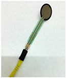
Robotics 11 00005 i015
Measures the amount of pressure from the fingers during pinching activity.
FSR: Tekscan FlexiForce A201 Sensor
Power bank (Zhongshan Pineng Battery Co., Ltd., Guangdong, China)
Robotics 11 00005 i016
Supplies 5 VDC, 2.1 A to power the Arduino, sensor, and servo motor.
Arduino Uno and electronic circuit (Arduino SA, Chiasso, Switzerland)
Robotics 11 00005 i017
The control unit receives an analog signal from the sensor and instructs the servo motor to rotate accordingly.
Control board: Arduino Uno
Microcontroller: ATmega328P (part of the Arduino Uno board)
Glove
Robotics 11 00005 i018
Central piece of the device that keeps the tendon cables in place.
Table 14. Pinch assistant performance details.
CharacteristicDevice Performance
Weight of glove and actuators320 g
Weight of device520 g
DOFs for index finger3
DOFs for thumb2
Bending angle of index finger~134°
Bending angle of thumb~100.76°
Force range8.5 to 13.9 N
Electrical input5 V DC 2 A
Operating hours~3.5 h continuously
Cost~RM 296.5
Table 15. Results of the a priori power analysis.
TestEffect SizeActual PowerPredicted Sample Size
T1 Detergent cup1.4090.814
T2 Clothes peg1.3640.984
T3 Golf ball1.0380.917
T4 Insect repellent1.0650.825
T5 Power plug0.8430.955
T6 Remote control1.1620.885
Table 16. The p-value of the normality test.
Testp-Values
With DeviceWithout Device
T1 Detergent cup>0.1>0.1
T2 Clothes peg>0.1>0.1
T3 Golf ball0.056>0.1
T4 Insect repellent>0.1>0.1
T5 Power plug0.05>0.1
T6 Remote control>0.1>0.1
Table 17. The paired sample pinch force test result in kg.
TestControlDevice
MeanSDMeanSD
T1 Detergent cup0.350.291.200.59
T2 Clothes peg0.310.160.680.33
T3 Golf ball0.810.381.390.75
T4 Insect repellent0.480.311.010.57
T5 Power plug0.570.331.020.60
T6 Remote control0.310.130.850.31
Table 18. The paired difference t-test for pinch force in kg.
Paired SamplePaired Difference
MeanStd. DeviationT-Value
T1 Detergent cup0.850.426.71 *
T2 Clothes peg0.360.235.26 *
T3 Golf ball0.580.434.52 **
T4 Insect repellent0.530.354.96 **
T5 Power plug0.460.403.80 **
T6 Remote control0.540.355.10 *
* p < 0.001; ** p < 0.005.
Table 19. The paired sample pinch test result for pinch force fluctuation (SD).
TestControlDevice
Mean *SDMean *SD
T1 Detergent cup46.0119.4633.0917.71
T2 Clothes peg50.1428.9932.9616.47
T3 Golf ball69.4034.0051.9023.1
T4 Insect repellent57.0722.1844.0616.73
T5 Power plug83.4046.2051.4024.10
T6 Remote control62.8631.1545.8617.72
* Mean of standard deviation.
Table 20. The paired difference results for pinch force fluctuation (SD).
Paired SamplePaired Difference
MeanStd. DeviationT-Value
T1 Detergent cup12.9211.653.68 *
T2 Clothes peg17.1715.003.80 *
T3 Golf ball17.4916.253.57 **
T4 Insect repellent13.0115.302.82 ***
T5 Power plug31.9631.423.37 **
T6 Remote control17.0020.172.80 ***
* p < 0.005; ** p < 0.01. *** p < 0.05.
Table 21. Comparison of improvements in pinch abilities with ball rolling training.
Output VariablesRef. [8]Current Study
Pinch forcep > 0.05 p < 0.05
Pinch force steadiness p > 0.05 p < 0.05
Note: p refers to the probability value.
Table 22. Comparison of improvements in pinch abilities with muscle strength training.
Output VariablesRef. [90]Current Study
Pinch forcep > 0.05 p < 0.05
Pinch force steadiness p > 0.05 p < 0.05
Note: p refers to the probability value.
Table 23. Comparison of exoskeleton devices performance.
DevicesWeight (g)No. of DOFsNo. of ActuatorsPinch Force (N)
Current study’s device5205213.9
ResearchSoftHand Pro5202220
X-Limb25313510.2
CommercialBebionic5396512.47
I-limb504656.54
Publisher’s Note: MDPI stays neutral with regard to jurisdictional claims in published maps and institutional affiliations.