1. Introduction
Artificial intelligence (AI) and robotics continue to grow and influence all aspects of industry and society, with the global market impact of robotics estimated to contribute up to 14% of global GDP by 2030, equivalent to around
$15 trillion at today’s values [
1]. Countries around the world are moving to exploit this emergent industry in order to improve productivity within existing market operations, e.g., oil and gas [
2], offshore wind [
3], manufacturing, agriculture, etc., and to capture revenue from high growth disruptive services within those sectors, such as robotic inspections using aerial [
4] and subsea platforms [
5], autonomous logistics etc. The future operation and maintenance of offshore wind farms outlines a transition from semi to persistent autonomy to reduce costs, improve productivity and to remove humans from dangerous deployment [
6,
7]. To meet this demand, new and innovative businesses in existing markets are establishing new cross sector supply chains, wherein underpinning technologies are being rapidly deployed into new market sectors. Along with this commercial expansion in robotics, governments are also strategically developing critical mass in robotics and AI research [
8]. In our research, we focus on the application of robotics to offshore renewable energy, due to the global commitment of offshore operators to robotics and AI.
Trust in the reliability and resilience of these autonomous systems is paramount to their continued growth, as well as their safe and effective utilization [
9,
10,
11]. Hauser [
12] reported the need for autonomous systems operating in real-world conditions to radically improve their resilience and capability to recover from damage. Rich [
13] expressed the view that there is a prospect for AI to solve many of those problems. Cave and Dihal [
14] claimed that a balanced view of intelligent systems by understanding the positive and negative merits will have impact in the way they are deployed, applied, and regulated in real-world environments.
A recent global review into aviation regulation for BVLOS (beyond visual line of sight) with UAVs (unmanned aerial vehicles) by the United States Congressional Research Office, highlighted that run-time safety and reliability is a key obstacle in BVLOS missions in all of the twelve European Union countries reviewed [
15]. A more recent study by [
16] also highlighted that, within a survey of 1500 commercial UAV operators, better solutions towards reliability and certification remain a priority for UAVs. Within the aviation and automotive markets there has been significant investment in diagnostics and prognostics for intelligent health management to support improvements in safety and enabling capability for autonomous functions e.g., autopilots, engine health management etc. The safety record in aviation has significantly improved over the last two decades thanks to advancements in the health management of these critical systems [
17].
In comparison, although the automotive sector has decades of data from design, road testing and commercial usage of their products, they still have not addressed significant safety concerns after an investment of over
$100 billion in autonomous vehicle research [
18]. Autonomous robotics face similar, and also distinct, challenges to these sectors. For example, there is a significant market for deploying robots into harsh and dynamic environments, e.g., subsea, nuclear, space, etc. [
19], which present significant risks along with the added complexity of more typical commercial and operational constraints in terms of cost, power, communication, etc., which also apply. Traditional commercial electronic products in the EEA (European Economic Area) have a CE marking, Conformité Européenne, a certification mark that indicates conformity with health, safety, and environmental protection standards for products sold within the EEA. At present, there is no similar means of certification for autonomous systems.
Due to this need, standards are being created to support the future requirements of verification and validation of robotic systems [
20]. For example, the British Standard Institute (BSI) committee on Robots and Robotic Devices and IEEE Global Initiative for Ethical Considerations in Artificial Intelligence and Autonomous Systems (including P7009 standard) are being developed to support safety and trust in robotic systems. However, autonomous systems require a new form of certification due to their independent operation in dynamic environments. This is vital to ensure successful and safe interactions with people, infrastructure and other systems. In a perfect world, industrial robotics would be all-knowing. With sensors, communication systems and computing power the robot could predict every hazard and avoid all risks. However, until a wholly omniscient autonomous platform is a reality, there will be one burning question for autonomous system developers, regulators and the public—How safe is safe enough? Certification infers that a product or system complies with legal relevant regulations which might slightly differ in nature from technical or scientific testing. The former would involve external review, typically by some regulators to provide guidance on the proving of compliance, while the latter usually refers to the reliability of the system. Once a system is certified, it does not guarantee it is safe—it just guarantees that, legally, it can be considered “safe enough” and that the risk is considered acceptable. There are many standards that might be deemed relevant by regulators for robotics systems. From general safety standards, such as ISO 61508, through domain specific standards such as ISO 10218 (industrial robots), ISO 15066 (collaborative robots), or RTCA DO-178B/C (aerospace), and even ethical aspects (BS8611). However, none of those standards address autonomy, particularly full autonomy wherein systems take crucial, often safety critical, decisions on their own. Therefore, based on the aforementioned challenges and state of the art, there is a clear need for advanced data analysis methods and a system level approach that enables self-certification for systems that are autonomous, semi or fully, and encompasses their advanced software and hardware components, and interactions with the surrounding environment.
In the context of certification, there is a technical and regulator need to be able to verify the run-time safety and certification of autonomous systems. To achieve this in dynamic real-time operations we propose an approach utilising a novel modelling paradigm to support run-time diagnosis and prognosis of autonomous systems based on a powerful representational formalism that is extendible to include more semantics to model different components, infrastructure, and environmental parameters. To evaluate the performance of this approach and the new modelling paradigm, we integrated our system with the robotics operating system (ROS) running on Husky (a robot platform from Clearpath) and other ROS components such as SLAM (simultaneous localization and mapping) and ROSPlan-PDDL (ROS planning domain definition language). The system was then demonstrated within an industry informed confined space mission for an offshore substation. In addition, a digital twin was utilized to communicate with the system and to analysis the system’s outcome, which is not the scope of this paper [
9]. Although we present and discuss the integrated models and technologies used in this autonomous mission, to provide a mission and autonomous system context, the main focus of this paper is on the modelling paradigm, based on ontologies [
21], i.e., the system model.
This paper is organized as follows. A state-of-the art review of diagnostics, prognostics, and robotic ontologies for reliability is presented in
Section 2.1 and
Section 2.2, respectively. Our modelling paradigm detailing the relationships, formalism, diagnosis automata, and the system ontology components is presented in
Section 3. Within
Section 4, the application of this approach and the modelling paradigm is explained in the context of the robotic self-certification.
Section 5 details the experiment and test procedures to evaluate the performance of the ontology. Results and analysis are contained in
Section 6. Finally,
Section 7 summarizes the primary findings of this research and a description of future research.
2. A State-of-The-Art Review
In this section we present an integrated review of diagnostics and prognostics, and assessment of robotic ontology state-of-the art applied to reliability analysis.
2.1. Review of Approaches of Diagnostics and Prognostics in Engineering Systems
Research into diagnostics has been one of the main challenges in autonomous systems and AI for decades. Several approaches have been proposed in the literature and are evaluated in this review for fault detection, methods such as: FTA (fault-tree analysis), FMEA (failure mode effect analysis) and its variants, model-based reasoning, qualitative reasoning, and assumption-based truth maintenance [
22]. Commercial tools have been developed to implement these traditional techniques, commonly referred to as DX (diagnosis). The field of control theory has also proposed other techniques on diagnostics which are known as FDI (fault detection and isolation) to adapt to different types of engineering systems whether these are static/dynamic (discrete or continuous), linear/nonlinear, or time-varying/time-invariant systems based mainly on mathematical modelling and energy transfer functions [
23]. A comparison between FDI and DX is given in [
24]. An advanced autonomous vehicle can be viewed from a top-down level as a DES (discrete event system), although it might include one or more CDS (continuous dynamic systems) as sub-systems or other different types of systems and it should be equipped with a fully automated diagnosis and prognosis that integrates theories from both FDI and DX.
The main modelling tools for DES are Petri nets and finite state automata (FSA), while Bond-graphs and multi-agents are used to model CDS for fault diagnostics purposes [
25]. A DES is a discrete-state event-driven system where the states’ progress depends entirely on the occurrence of asynchronous discrete events over time [
26]. Nevertheless, in most engineering systems, the states and events of DESs are typically not sufficiently accurate [
27]. FSA are used to model DES as well as Stochastic DES [
28,
29,
30,
31,
32].
In recent work, a diagnoser is constructed from the main FSA of the system [
33]. The notion of diagnosability was then formally introduced and applied as the term used to indicate that it is possible to detect with finite delay occurrences failures of any type using the records of observed events. This notion is useful when constructing the diagnoser, using an algorithm, from the system model. It was claimed that testing diagnosability is a path-finding problem. It was further claimed that an efficient propositional approach to solve a path-finding problem, such as AI planning and model-checking, is to reduce the problem to a logic problem. The FSA diagnostic based approach was presented [
34] wherein the diagnoser takes the output sequence of the system as its input and generates at its output an estimate of the condition (failure status) of the system. In those techniques, the system and the diagnoser do not have to be started at the same time, and there is no information about the state or even the conditions of the system before the initialization of the diagnoser.
The symptoms-fault relationship is the basis for most fault-finding problems, whether achieved manually or via automated processes, and is used in the majority of previous and recent approaches. However, in our view, making a clear distinction between symptoms and faults in an automated diagnosis system is impractical if not impossible. This is because, firstly, not all parts of the system are sensed (using internal sensors). Secondly, a fault may lead to a symptom (sensed component) or to another fault (which is a non-sensed component), or faults and symptoms may lead to other symptoms and faults. This shows that the relationship between symptoms and faults are not one-to-one but many-to-many and it is bi-directional. Therefore, the first critique on these approaches is that it is very difficult to determine which fault was the cause of the other, especially in multiple faults, intermittent faults, or incipient fault scenarios. Hence, the prior methods are constrained to simplified single fault cases. The coverage of the above approaches is limited to certain fault types and to specific scenarios. Although FSA is a suitable tool to model the different states of a component in a system, none of the approaches address the challenge of scalability for whole systems. The second critique is that none of the previous efforts made a distinction about the different stages in fault finding; troubleshooting, fault detection, fault isolation, fault diagnosis, or fault prognosis. Furthermore, as autonomous vehicles add more requirements to the diagnostics and prognosis systems embedded within the system, for example the data driven decision making within the controller and planner, none of the previous works demonstrated how their approaches can be embedded into operational autonomous vehicles. Hence, our research aims to address these challenges within a more powerful system based on a reliability ontology. The following section evaluates the current state-of-the-art in ontology research applied to reliability.
2.2. Assessment of Robotic Ontology Applied to Reliability
Within robotics and AI there are several sub-disciplines of expertise and ontology is one such sub-discipline. In the last 10 years, based on a keyword search of ontology-robotics-reliability-diagnosis, and on a survey carried out by IEEE-SA P1872.2 Standard for Autonomous Robotics (AuR) Ontology, there has been around seventy publications relating to ontology and autonomy for robotics. Within these publications several authors have applied ontology as a knowledge-based scheme (Knowledge Representation), within a system to support robotics autonomy, such as SMERobotics [
35], KnowRob 2.0 [
36], CARESSES [
37], open-EASE [
38], ORO [
39,
40], and SIARAS [
41]. These prior works focused on one or more of the cognitive functionalities in a robotic system, i.e., reasoning scope. They covered a spectrum of cognitive functions, which according to the classification made by [
42,
43] are: recognition and categorization, decision making and choice, perception and situation assessment, prediction and monitoring, problem solving and planning, reasoning and belief maintenance, execution and action, interaction and communication, and remembering, reflection, and learning. The ontology scope of these prior works varies and it depends on the functionalities of the target robotic system, i.e., concepts that were modelled in the ontology are related to: object names, environment, affordance, action and task, activity and behaviour, plan and method, capability and skill, hardware components, software components, interaction and communication [
44,
45].
A primary motivation for the use of ontologies within robotics is that these knowledge-based approaches offer an expandable and adaptable approach for capturing the semantic features to model robot cognitive capabilities. Hence, this offers an agile and rapidly tunable capability to the challenge of capturing dynamic safety compliance and mission operability requirements which will impact directly onto the real-time safety case, reliability and resilience of a robotic system. In other words, the developed ontology can be applied to several and different tasks that humans and robots can perform cooperatively within a defined infrastructure, mission profile and environment. Furthermore, when considering a fleet distribution of robotic platforms, or swarms, the ontology provides a cyber-physical interface to cloud, web-based service robots, such as RoboEarth [
46] and openEASE [
47], that enable robots to collect and share knowledge of missions. This knowledge enabled architecture provides a means of sharing knowledge via the ontology, between different robots, and between different subsystems of a single robot’s control system in a machine understandable and consistent presentation (i.e., symbolic presentation).
Therefore, attempts have been made to create CORA (core ontology for robotics and automation), which was developed in the context of the IEEE ORA (Ontologies Robotics and Automation) working group. However, creating a complete framework, which is a highly complex task, was out with the scope of the ORA working group initiative [
48]. The 1872–2015 IEEE Standard Ontologies for Robotics and Automation defines an overall ontology which includes key terms as well as their definitions, attributes, constraints, and relationships. Sub-parts of this standard include a linguistic framework, generic concepts (an upper ontology), a methodology to add new concepts, and sub-domain ontologies [
49]. The core ontology was utilised in some projects such as [
50,
51]. However, the core ontology is too generic for complex applications, overlooking complex mission and robotic platform sub-system interdependencies [
44].
Following review of the literature, we have selected and classified four internationally leading projects and highlight their key contributions and limitations, which have informed the design of our system ontology. In addition, the four selected projects are accessible, transparent and currently maintained:
KNOWROB (Knowledge processing for Robots) is widely used and arguably one of the most influential projects due to its use of knowledge-based reasoning for autonomous robots. It has been used in several research initiatives including the European projects RoboHow [
52], RoboEarth [
46], SAPHARI [
53], and SHERPA [
54]. The current development of KNOWROB has shifted towards the integration of simulation and rendering techniques into a hybrid knowledge framework [
44,
45] The KNOWROB framework does not have any diagnosis or prognosis features.
The SDRL (Semantic robot description language), an extension to KNOWROB, was devised to represent robot hardware, software and capabilities. The main mechanical hardware components can automatically be imported from a URDF (Unified Robot Description Format) and are annotated with additional semantic information (such as Depends-On). For example, one can annotate semantically meaningful groups of links such as the left arm or the right gripper. This allows the system to reason about the robot’s configuration. In addition, SRDL provides inference mechanisms that operate on the robot model and can check which dependencies of action descriptions are available on the robot. This further allows to identify missing components or capabilities.
The ROSETTA ontology focuses on the relationships between robotic devices and skills. For example, every device can offer one or more skills, and every skill is offered by one or more devices. Production processes are divided into tasks (which may be considered specifications), each realized by some skill (implementation). Skills are compositional items, of which there are primitive skills (non-divisible) and compound ones. Skills may be executed in parallel, if the hardware resources and constraints allow it [
55]. The Rosetta Framework also does not have any diagnosis or prognosis features.
The S4R (Semantic Web for Robots) is an ontology implemented by Juarez [
56] for robotic components. It uses a collaborative knowledge acquisition system for encoding information about robotic devices. The ontology covers component capabilities and is extended by a rule language to model more complex capabilities and also uses a reasoning engine. In this approach, the author uses various semantic Web technologies and mixes elements from the robotic domain with virtual worlds. The SWR framework does not have any diagnosis or prognosis features.
In the PANDORA framework [
57], ontologies are used as a way for the robot to organise the knowledge about the world, not just in geometric concepts, but attaching a semantic label. In particular, a diagnostic module has been developed in order to detect a thruster failure, with a link between the degrees of freedom of the vehicle and the executable actions. A claim was made by the author that whilst there is a substantial literature on the subject of diagnosis in general, in practice it reduces to the specification of an ontology of fault conditions that can be reasoned with as status data changes during task execution. It was further claimed that previous work inferring facts about state and mode from noisy systems based on data has been carried out in model-based reasoning community.
Prior research on ontology for reliability has focused on initial applications of diagnostics and prognostics. It has been limited to specific applications of a robot’s hardware configuration or single fault detection (i.e., at component level). The semantic relationships used are simplified and do not reflect the inter-dependencies and the complexity of the system as a whole. Therefore, the objective of our research which is presented in this paper is to model the whole system and to cover a wider range of faults and failure.
3. The System Ontology Components
In this section we describe the system ontology components, the semantics of the relations, the diagnosis automata, and the ontology formalism.
Figure 1 shows the components of the system ontology. The System Model component within the system ontology is the focus of this paper which is designed based on a complex set of semantic relationships that encompass a variety of engineering systems (e.g., mechanical and electrical). Our objective is to address the limitations in system models (semantics relationships and automatons modelling) for fault detection, diagnosis and prognosis (FDDP). This is a highly complex problem wherein we capture the inter-dependencies across critical hardware components and executive decisions. This will quantify how faults can cause failure and how this will have an impact on the decision-making process.
3.1. The Relationships between Things (Parts)
The semantics of the relations is based on the philosophy that there are different types of relationships between the different parts of a system. This means the physical links and connections, whether it is direct or indirect, between the parts of a system can be modelled via a well-defined set of semantic relationships. The objective is to build a model of that system with the aim that it is scalable, generic and applicable for other tasks and systems. A part of any system can be described by two things—its name and its status. The seven types of relationships that may hold between parts (described by their names and status) of a system are: ‘causality’, ‘implication’, ‘prevention’, ‘hierarchical’, ‘composition’ (strong association), ‘aggregation’ (weak association), and ‘optional’ (or ‘recommended’). For example, x cause(s) y, x imply(s/ies) y, x prevent(s) y, x (is) supper-of y, x (is) composite-of y, x (is) aggregated-with y, x (is) optional-part-of y. Modality can be combined with the three binary relations: ‘causality’, ‘implication’, and ‘prevention’ to show the degree of certainty in the relationship. Modal verbs combined with those relations are must (absolutely certain), would (really certain), should (very likely), might/may (possibly), or could (less possible). For example, x might-cause y, x must-cause y. Also, it is important to notice that the implication relation is the material conditional and not the known conditional statement in a procedural programming language. Besides being able to express degree of certainty, modality can be used to express different levels of abstractions. For example, the relationship cause-high-temperature can be declared in the knowledge repository without specifying its domain and range and without putting any restrictions on the relationship. This would make relationship more abstract, it would also give a higher semantic level, meaning that ‘there is a thing that causes a temperature to another thing, to other things, or to itself’. The relationship would cover a very large number of members from the domain and the range. For such an abstract level of relationships, two individuals can bind together by more expressive representation such as semantic rules at a later stage. On the other hand, the definitions of relations can be very generic, meaning that they can be used for more than one domain and more than one range, they are not made for specific components or parts in the system. For example, cause-high-temperature can be used between any two types of component that heats up.
Another type of relationship which is defined outside the model but helps in building the model is the ‘positive correlation’, whether it is weak or strong, between the parameters of two or more parts. This is learnt by some tools (machine learning tools) and then represented as one of the seven defined relationships. This means dependency between non directly linked components is learned by external tools, e.g., machine learning, then these learned dependencies can be asserted into the model and the knowledge base.
In addition, each part has its own properties which can affect the relationships between the parts of the system such as: ‘dependency’, ‘reusability’, ‘validity’, and ‘availability’. For examples, x (is) stand-alone, x (is) reusable, x (is) valid, and x (is) available. The brackets which includes ‘s’ or ‘is’, written (s) and (is), are used to distinguish between the semantics of relation from its syntactic use in the English language.
Binary relationships = {causality, implication, prevention, hierarchical, composition, aggregation, optional}
The relationships between the components are made at the top-level between the components or at bottom-level between the different states of the components. The different states of the components are modelled as finite state automatons, called the diagnosis automata.
3.2. The Diagnosis Automata
A diagnosis automaton is constructed for each critical part of the system, i.e., motor, battery, motor driver, or wheel, single component or an integrated device, whether it is sensed or non-sensed. A specific part of a system might have its own different states. For example, a component can take 5 s to warm up or to cool down, this means its state changes from On to Ready or from Working to Off. States can be classified into three categories: sensed states (e.g., component’s temperature), possible states (collected from experience, observations, environment, or historical data, e.g., component can break easily), and normal states (extracted from datasheets, e.g., a component can take 5 s to warm up).
states = {sensed, possible, normal}
Sensed states = {low current, high temperature, …}
Possible states = {broken, aging, degrading, abnormal behavior, ...}
Normal states = {on, off, ready, working, ...}
Events that make the states of the components change can be internal, temporal, spatial, or external (expected events with different degrees of possibility). Events on the transition are:
Events = {internal, time-driven, space-driven, external}
Intuitively, sensed states can be reached by internal events, normal states can be reached by either time-driven or space-driven events, and possible states can be reached by external events. A new binary relation is created to make the transition from one state to another. For example, “s1 transit-on-high-voltage-to s2”, “s1 transit-after-5-s-to s2”, “s1 transit-at-location-x-y-z-to s2”, and “s1 transit-when-hit-to s2”. The set of Binary relationships now includes the new relation ‘transitional’, which can be written as transit-TranExp-+[EventDes-]to, where ‘TransExp’ is any of the transitional expressions that express relationships in: time, space, or logical sequence, such as ‘when’, ‘on’, ‘after’, ‘at’, or ‘then’ (as an example for logical sequence, “s1 transit-after-oneSecond-to s2”). Using regular expression terminologies; the ‘[]’ around ‘EventDes’ means it is optional to give a description to the event and it is one at most, the ‘+’ after ‘TranExp’ means there is one or more transitional expressions. Any of the transitional events, especially the external ones, can have modality as well, for example, “s1 may-transit-when-hit-to s2”. This means that the relationships between the states allow the construction of deterministic or stochastic automatons.
Therefore, while the ‘transitional’ relationship relies on events to change the state of the component based on the information in the datasheets of the components, the other binary relationships are not transitional in nature and they don’t rely on events but in the prior knowledge and experience of the system.
3.3. The Model
The model initially is based on the hierarchical relationship to start with. Two models are created, the semantic of the hierarchical relationship in the first model is an ‘is-type-of’ relationship, while in the second model it is an ‘is-linked-to’ or ‘is-connected-to’ relationships, for example, “x is-connected-to y”. This means the system to be diagnosed has two models, the first one is more generic than the second and it can be adopted easily by other systems. The second model is the concern of this paper since the first model is just representing the taxonomies of the system components, for example, “temp-sensor is-type-of sensor”. The other relationships are semantically declared in the second model between two different components and between two specific states in different automata. For example, “state2_x causes-high-temp-to state4_ y’. The relationship ‘causes-high-temp-to’ between state2 and state4 is declared in the model, abstractly, without binding to any specific states or components, while the relationship ‘may-cause-high-temp-to’ between state2 and state4 is defined between members of state2 (the domain) and all members of state4 (the range). The relationship ‘may-causes-high-temp-to’ is inferred (or asserted) by the reasoner, while the relationship ‘causes-high-temp-to’ is inferred by the semantic rules.
3.4. The Formalism
The formalism used for modelling is description logic (DL) which is a subset of first order predicate logic. Both have limitations which are extensively discussed in the literature [
21]. Although they provide an excellent base for the modelling process, those limitations make them insufficient for complex diagnostics tasks. For this reason, extra semantics are formulated to describe relationships between the parts of the system as mentioned above. To broaden the accessibility of this paper no formal language is used to describe the logic and semantics of the models. Some of those semantic requirements of the methodology proposed in this paper can be expressed directly using the ontology formalism, some others extend the ontology. Therefore, ontology is a suitable platform for experiments and providing the proof of concept. Parts (as concepts) of a system are represented as classes (sets) in a hierarchical manner (taxonomies). Classes can be made disjoint. Each set has zero or more individuals. Data (values) can be assigned to individuals. The relationships between parts of the system are declared as facts between the classes, and then the individuals (objects) bind during the reasoning process. The relationships between classes/sets are represented as a relation between Domain and Range. Other characteristics can be added to the relation, so that the relation can be made functional, transitive, symmetric, reflexive, and their inverse. Basic semantics of the relations can be expressed directly using the ontology formalism and others use Semantic Web Rules (SWRL). After the model of the systems is built, a reasoner is used to check the consistency of the model and rules are applied. Further queries can be made using the Description Logic (DL) or SPARQL queries. The diagnosis automaton (or diagnoser) is the automaton which define the semantics for the states and arcs for each part of the system.
4. The Example: An Autonomous Confined Space Inspection
In this section we show how to construct the automaton for each component and then how to relate them using the semantic relationships.
In this beyond visual line of sight (BVLOS) case study, we consider three critical sub-systems of the robotic platform: battery, motor, and motor drivers. These sub-systems are monitored by internal sensors, for example, voltage & charge for the battery, temperature for the motor, and temperature & current for the motor driver [
58].
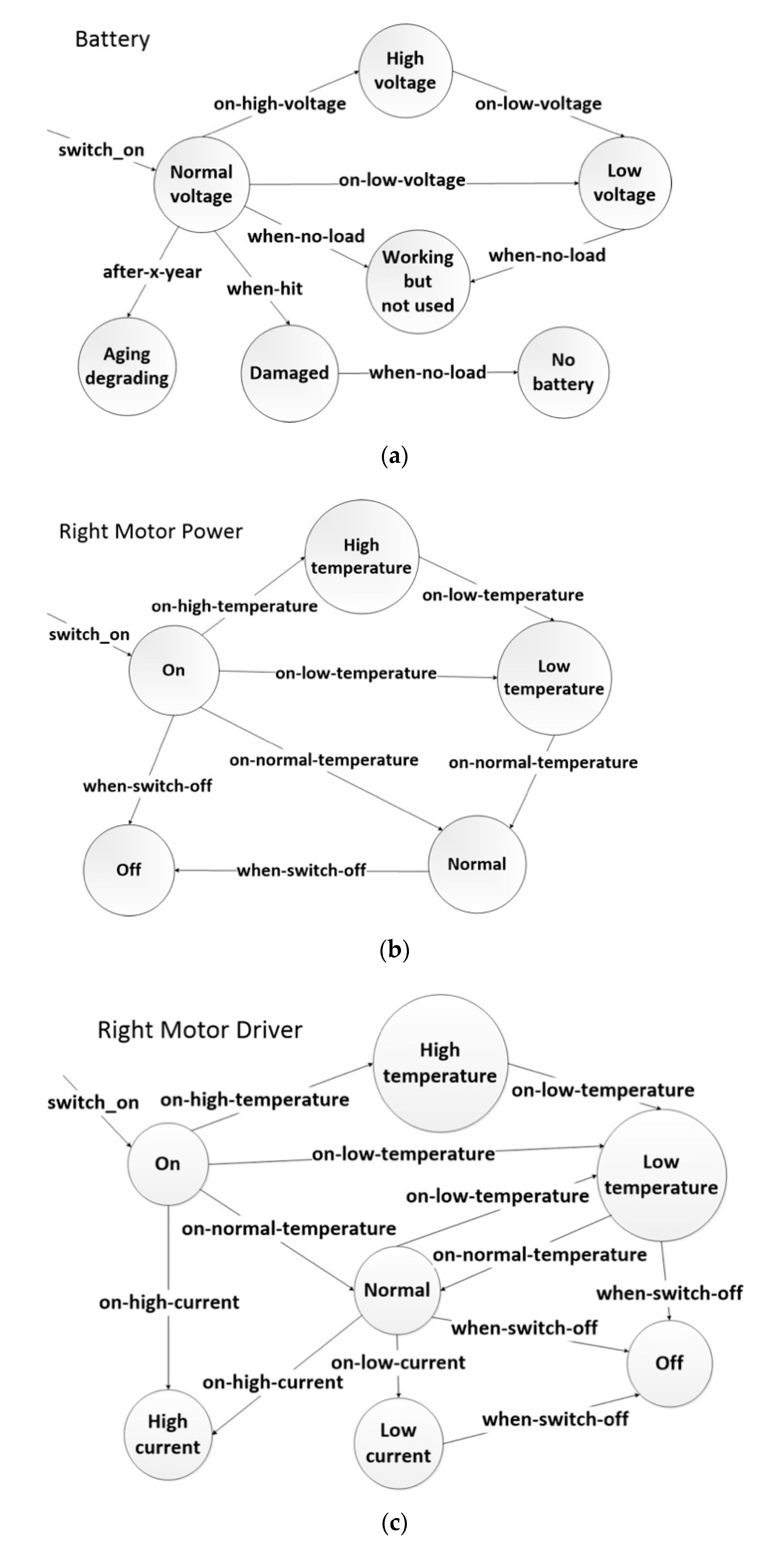
Diagnosis automata (diagnosis automatons),
Figure 2a–d, are constructed—as a first step—for each of the sensed (observed) components: battery, motor, and motor driver. In addition to those sensed components another diagnosis automaton is shown for the wheel which is a non-sensed component. Each automaton in
Figure 2 describes the states of specific components. A component can have any number of sensed states, possible states, and normal states. A non-sensed component (such as the wheel in our example) can have any number of possible and normal states only.
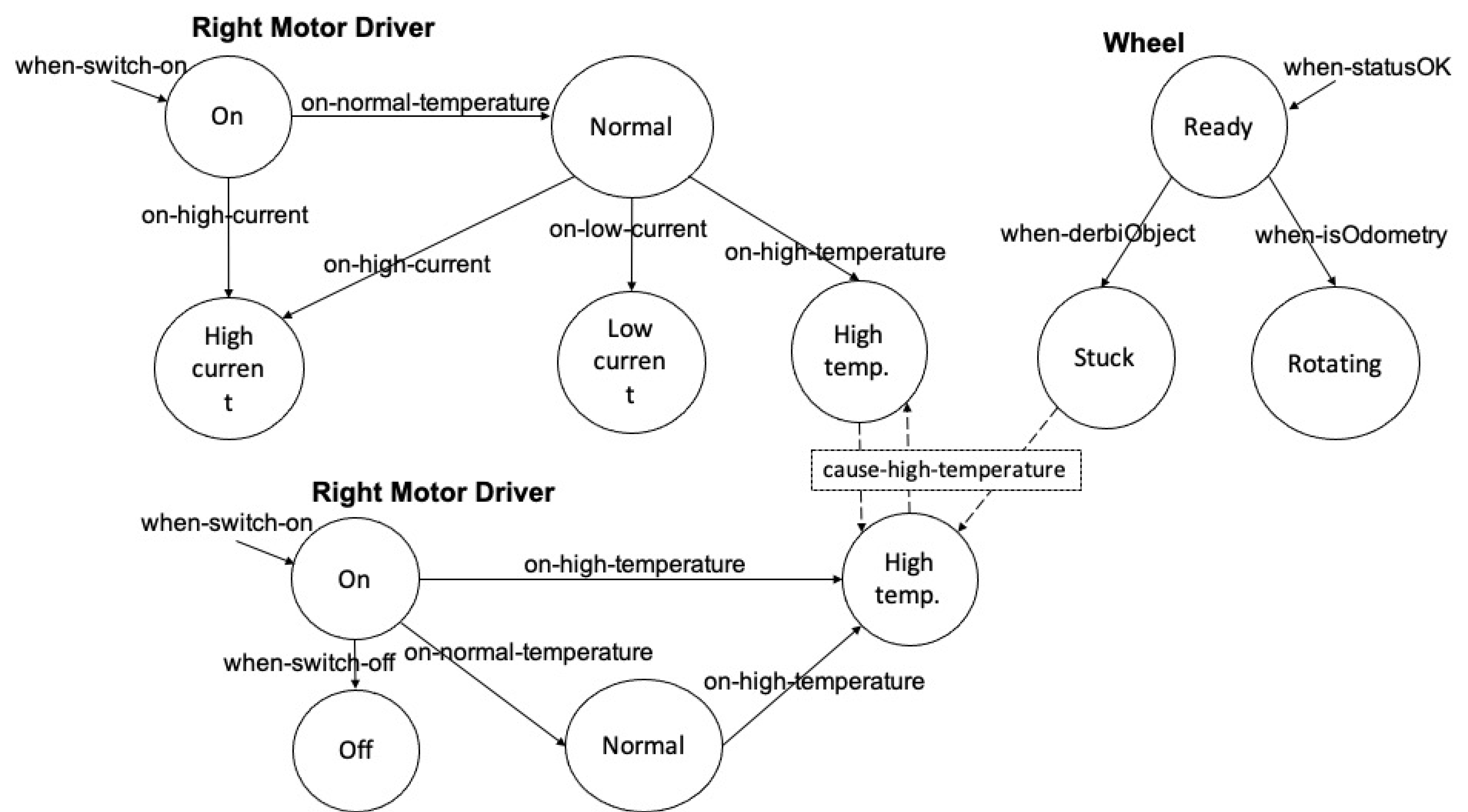
The following step is to link the automatons together via semantic relationships.
Figure 3 shows the three automatons described in
Figure 2b–d, connected together via semantic relationships. The binary semantic relationships relate specific states, in different automatons for different components, with each other’s. For example, the High-temperature state of the Right_Motor_Driver automaton is connected to the High-temperature state of Right_Motor_Power automaton via the relationship
cause-
high-
temperature. This relationship expresses that a high temperature in the motor driver causes (or might cause) a high temperature in the motor and vice versa; i.e., it has a symmetric characteristic. The Stuck state of the Wheel automaton is also connected to the High-temperature state of Right_Motor_Power automaton. This means when the wheel is stuck it also causes (or might cause) a high temperature in the motor, but it has a non-symmetric characteristic of the relationship. The following section via a detailed example shows how semantic rules will pertain to and employ this semantic relationship.
5. Implementation and Experiments
The system ontology is implemented onto ROS for operation during an autonomous inspection using the Husky platform. The mission space was a confined space environment built for replicating offshore oil and gas, and renewable energy operations. Husky’s hardware components are modelled in the implemented ontology. The durations of the live missions were between 5 and 30 min in duration. Faults were produced at randomised intervals during the mission, and non-induced faults inherent to the system itself were also encountered during the live missions and were mitigated, without inducing faults, by the ontology of the robot. The system ontology is created using the relationships and the related diagnosis automatons as shown in
Section 4. The complete autonomous inspection mission of a generator within a confined space is shown in
Figure 4.
The knowledge repository,
Figure 5, a knowledge base that is accessible for run-time diagnostics, contains more knowledge than is required by the examples shown here, therefore we limit the discussion on specific sections of the ontology which are related to the examples.
Figure 6a shows the top-level section of the ontology hierarchy and the two main branches of the ontology; to the right is the branch presenting the model of Husky’s hardware, while the left branch is the mission formal specification requirements, and at the bottom of that branch there are different classes which present the published data from ROS-Husky (such as: the diagnostic topic, the status topic, and the hardware topic). At run-time and during the mission, data is populated from ROS into the ontology, where each individual in the ontology contains the whole set of data at each interval (approximately 1 s).
Figure 6b expands the right branch of
Figure 6a further (the battery feeds the micro controller unit with power) to show other components connected to the battery (the circle symbol beside the node name in the figure indicates a concept and the diamond symbol indicates an individual).
For each hardware component, reference data (usually taken from the component’s datasheet) is associated with the appropriate class, which is represented as
has relationship using the data property feature in the ontology.
Figure 6 shows the main components of the ontology: classes/subclasses, data properties, object properties, and their assertions.
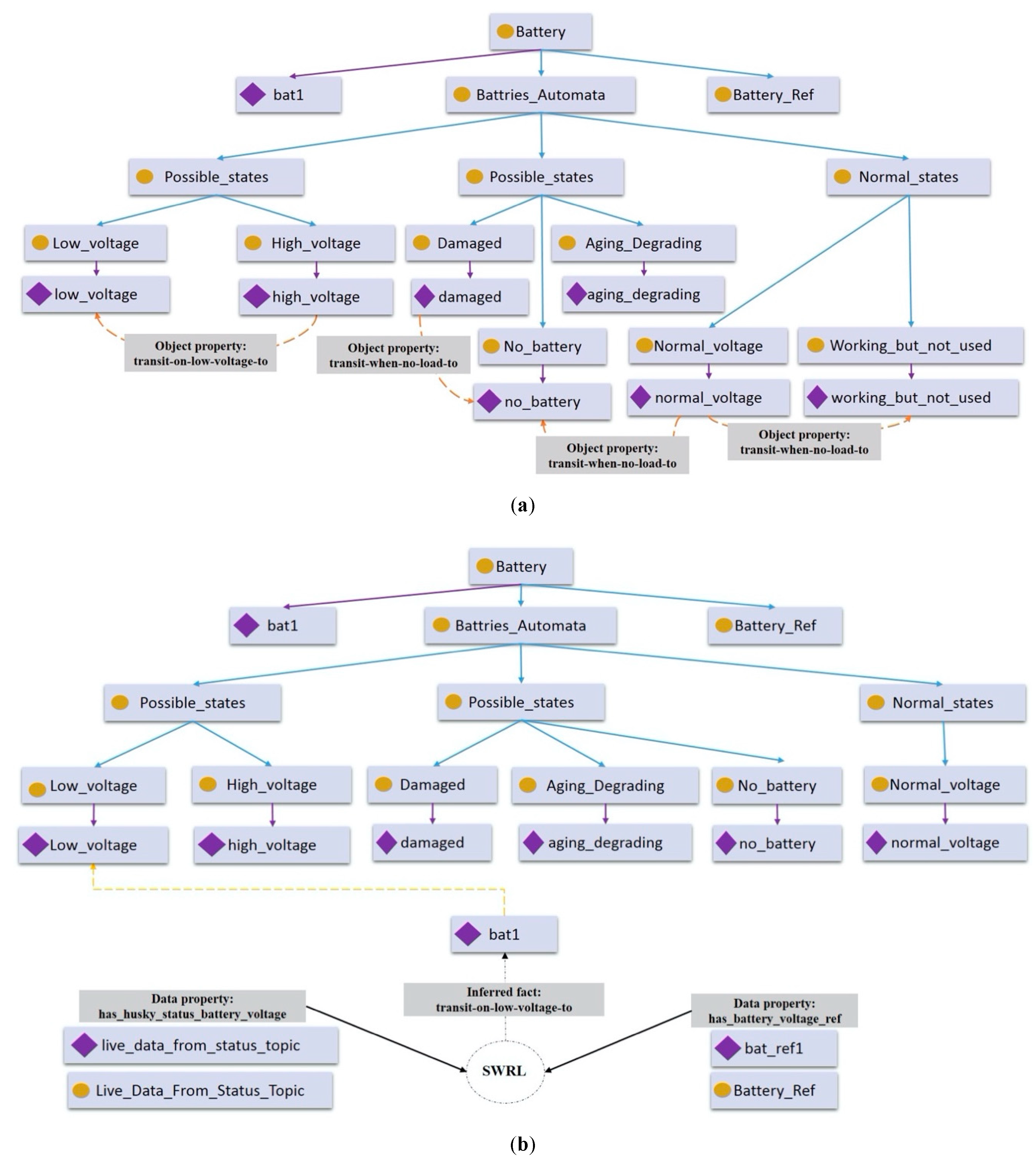
In the diagnosis automaton of the battery,
Figure 7a,b, a single fault scenario at the prognosis stage is demonstrated. The state of the battery is identified based on the events received from the vehicle internal sensors via the Status topic in ROS in this particular scenario (it can also be external events in another scenario).
Figure 7a shows the relationships (an object property relates any two individuals together of particular classes) between the states, and
Figure 7b shows the SWRL rule(s) when the relationship is being inferred based on the events received. All the diagnostic and prognostic semantic rules are implemented using the SWRL syntax.
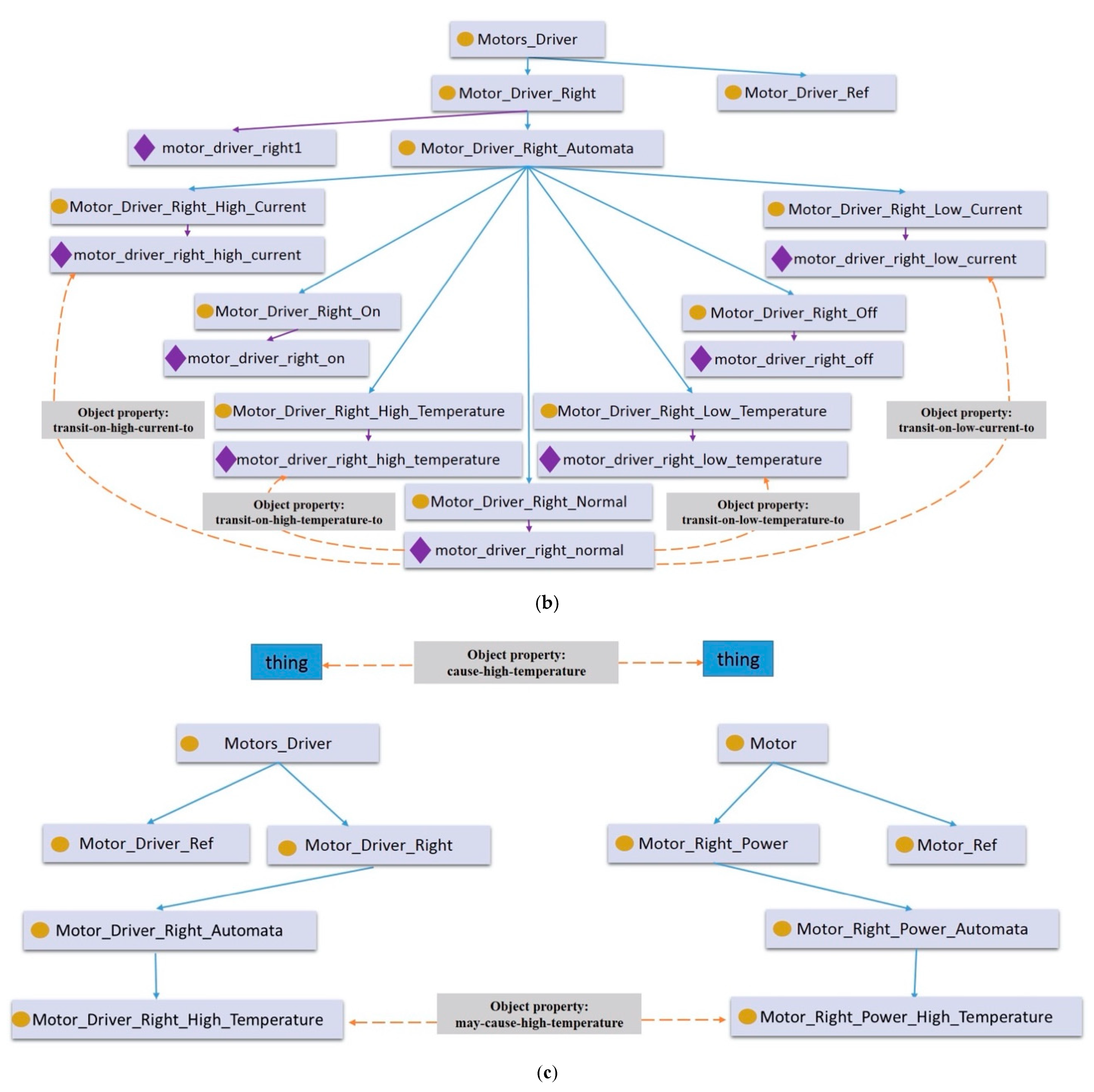
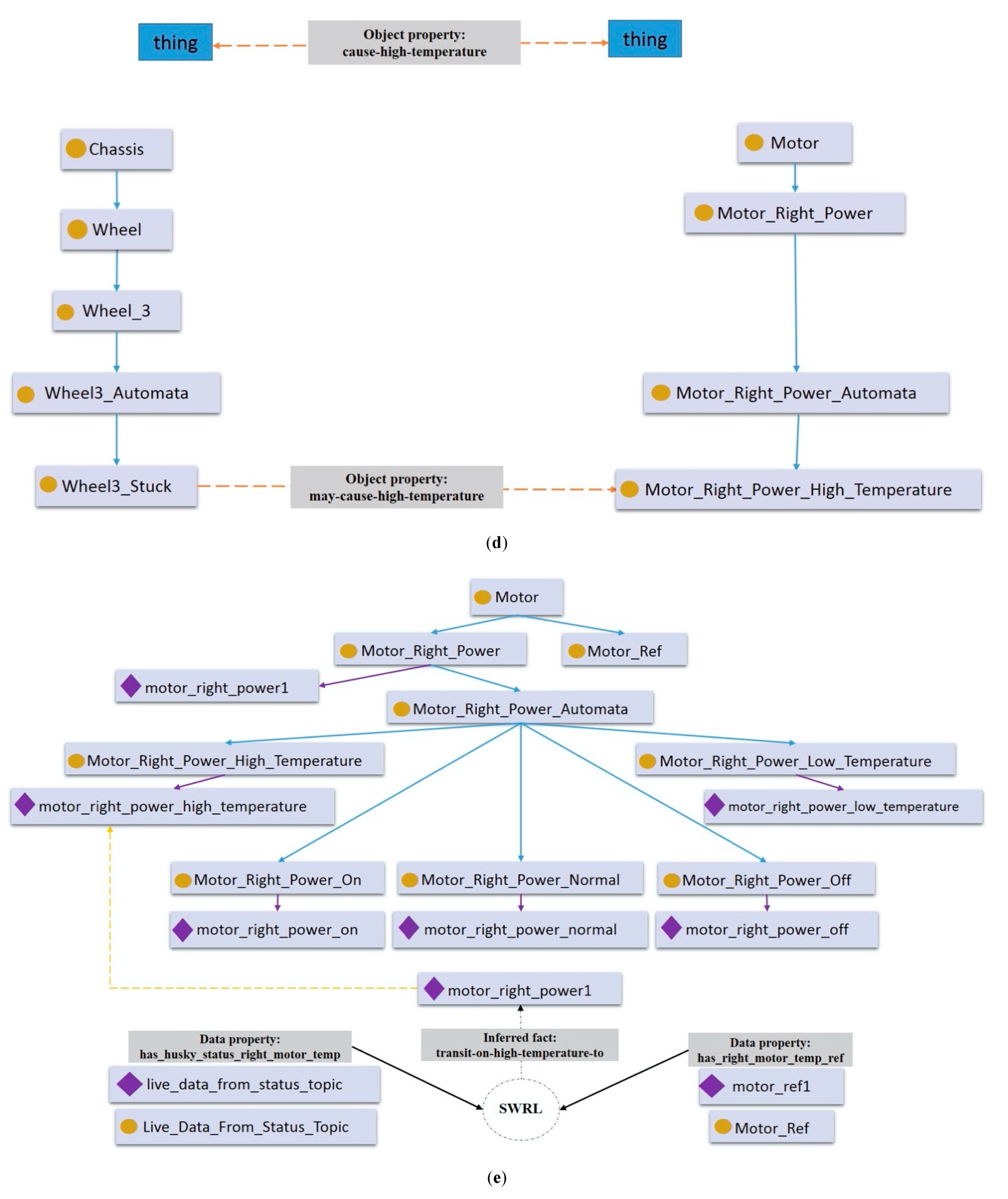
A multiple-faults scenario is demonstrated in
Figure 8a–g, a motor can heat up because of the motor driver or because of the wheel.
Figure 8a shows the diagnosis automaton of the motor with the relevant relationships between the states, while
Figure 8b shows the diagnosis automaton of the motor driver with the relevant relationships between the states.
Figure 8c shows the abstract relationship cause-high-temperature between two things, and the asserted (or inferred) relationship may-cause-high-temperature between the Motor_Right_Power and the Motor_Right_Driver (an object property is declared between two classes but implemented between two individuals of these particular classes). Those two relationships are declared once in the ontology, the first without domain and range (and it is a symmetric), while the second can be declared with more than one domain(s) and range(s) and it is also symmetric.
Similarly,
Figure 8d shows the same abstract relationship cause-high-temperature, and the asserted (or inferred) relationship may-cause-high-temperature between the Motor_Right_Power and the Wheel, which is non-symmetric.
The state of each component is determined by SWRL rule(s) based on live data from the sensors. The SWRL rule(s) check live data against the reference data for each component. If a rule is fired a fact is inferred by the reasoner and the state of the component is asserted. In
Figure 8e the individual “motor_right_power1” of the class Motor_Right_Power has made a relation with the individual “motor_right_power_high_temperature” as a result of firing the rule and the insertion of the fact transit-on-high-temperature–to (the object property).
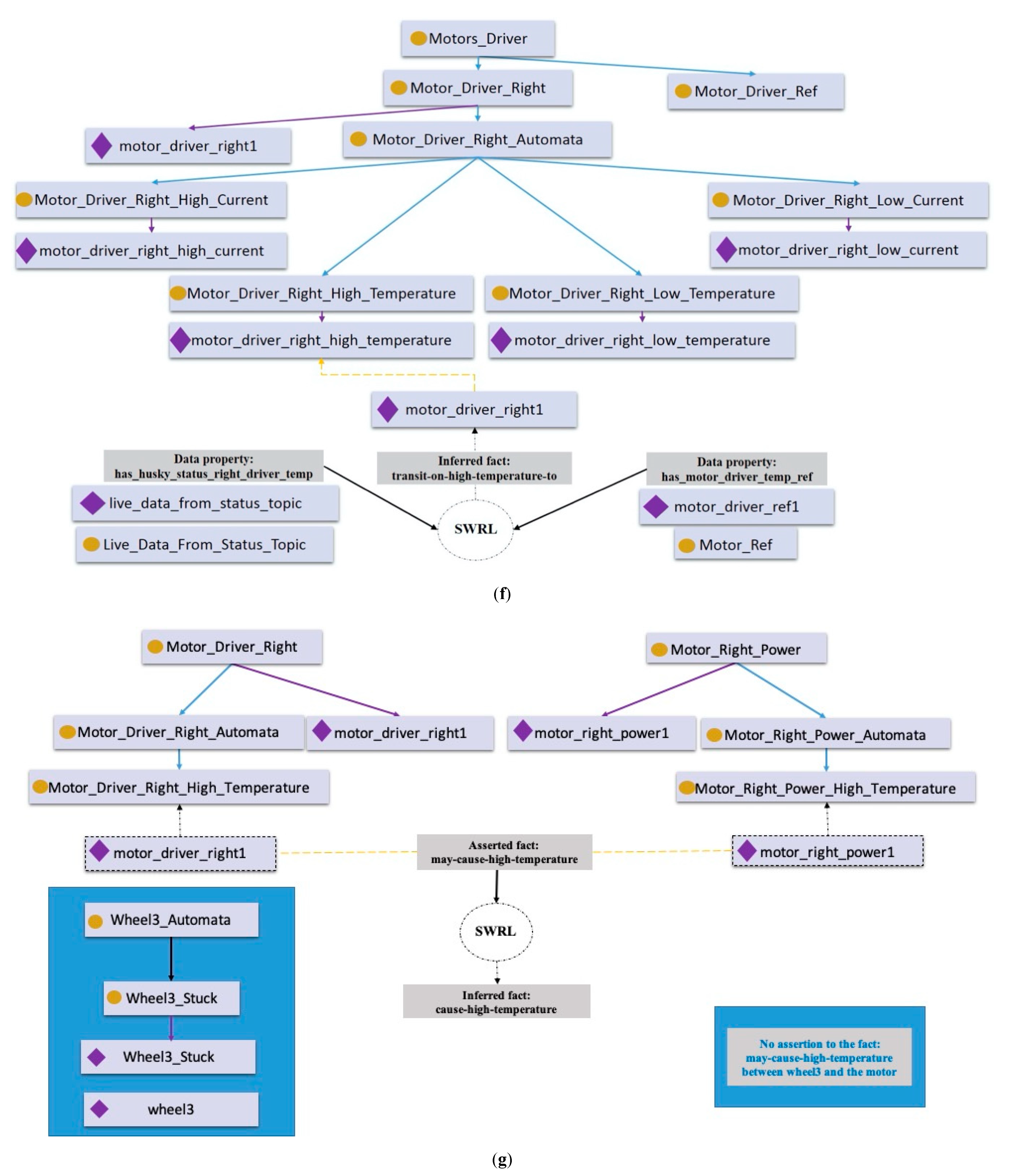
In
Figure 8f the individual “motor_driver_right1” of the class Motor_Driver_Right has made a relation with the individual “motor_driver_right _high_temperature” as a result of firing the rule and the insertion of the fact transit-on-high-temperature–to (the object property).
At this stage, the state for each component is determined. The state of the right motor power is known, and the state of the right motor driver is also known. At the same time, the reasoner cannot make any assertion between any of the wheel’s states and the motor’s states. This would confirm that the high temperature in the motor is caused by the motor driver as shown
Figure 8g.
However, because the characteristics of the relationship may-cause-high-temperature between the motor and the motor driver are symmetric, it can be said that the motor caused high temperature to the motor driver, or the motor driver caused high temperature to the motor.
6. Analysis and Results
Testing, Verification, and Validation of software is an area of research wherein there are many different fields of thought, this is due to the varying structure of software systems and software development life-cycle approaches. There are approximately 110 testing methods used for verification and validation (V&V) of conventional software in which 45 of these can be used for AI systems [
59]. With autonomous robotic systems V&V is even more complex; hybrid, and often safety-critical; this makes their formal specification and verification uniquely challenging. Though commonly used, testing and simulation alone are insufficient to ensure the correctness of, or provide sufficient evidence for the certification of, autonomous robotics [
60,
61]. Verification and validation are usually carried out during and after the requirements/design and implementation stages [
62]. Some of those testing methods are manual, semi-automated, or fully automated. Some methods are static, and some others are dynamic. Some of these rely on building a model for the software, then a checker will test the model, e.g., model checking, whereas others rely on formal methods. In general, the target of testing is to detect or discover anomalies or invalidities in the software system under test. Once those anomalies/invalidities are fixed and maintained this proves the correctness of the software system under test for its predefined specification.
At the knowledge acquisition and elicitation stage when designing the ontology, support was given by a platform hardware (Husky, the robot) expert. The verification and validation procedures for the ontology comprised of three main steps: (1) automated verification of the ontology to prove its consistency and completeness, for the components/circuits/subsystems under test, by the reasoner Pellet [
63], (2) semi-automated generation of test cases for the purpose of validation, (3) manual validation of the reasoner’s results by the knowledge engineer and the platform hardware expert. Testing the functionality of the ontology as part of the whole system was performed in three stages: (1) desktop and simulation testing, (2) pre-mission testing on the real hardware and platform, and (3) live mission testing.
Figure 9 depicts the sequence of the knowledge engineering process.
In addition to detecting or discovering anomalies/invalidities in the system under test, the end goal is to be able to verify that the behavior of the robot matches the specification requirements, and it behaves correctly. The five semi-automated test cases are:
Prediction of low battery voltage.
Prediction of high temperature in the motor driver.
Multiple faults in motor and motor driver current.
Root cause analysis for two components affecting a third one.
A possible problem in a non-sensed component, a wheel.
The system was able to pass all of the test criteria.
Table 1 simplifies the experiments results.
Even though, the size of the ontology was relatively small (2KB before populating the data), and the relationships, the diagnosis automatons, and the semantic rules were manageable and maintainable, the results were promising. It would be more challenging when more data populate the ontology for complexity and scalability tests. Two complexity and scalability tests were conducted:
The ratio in size between the theoretical size (raw data to be populated into the ontology) and the actual size of the ontology after raw data was populated into it. This test indicates the complexity of the space required (storage or working memory).
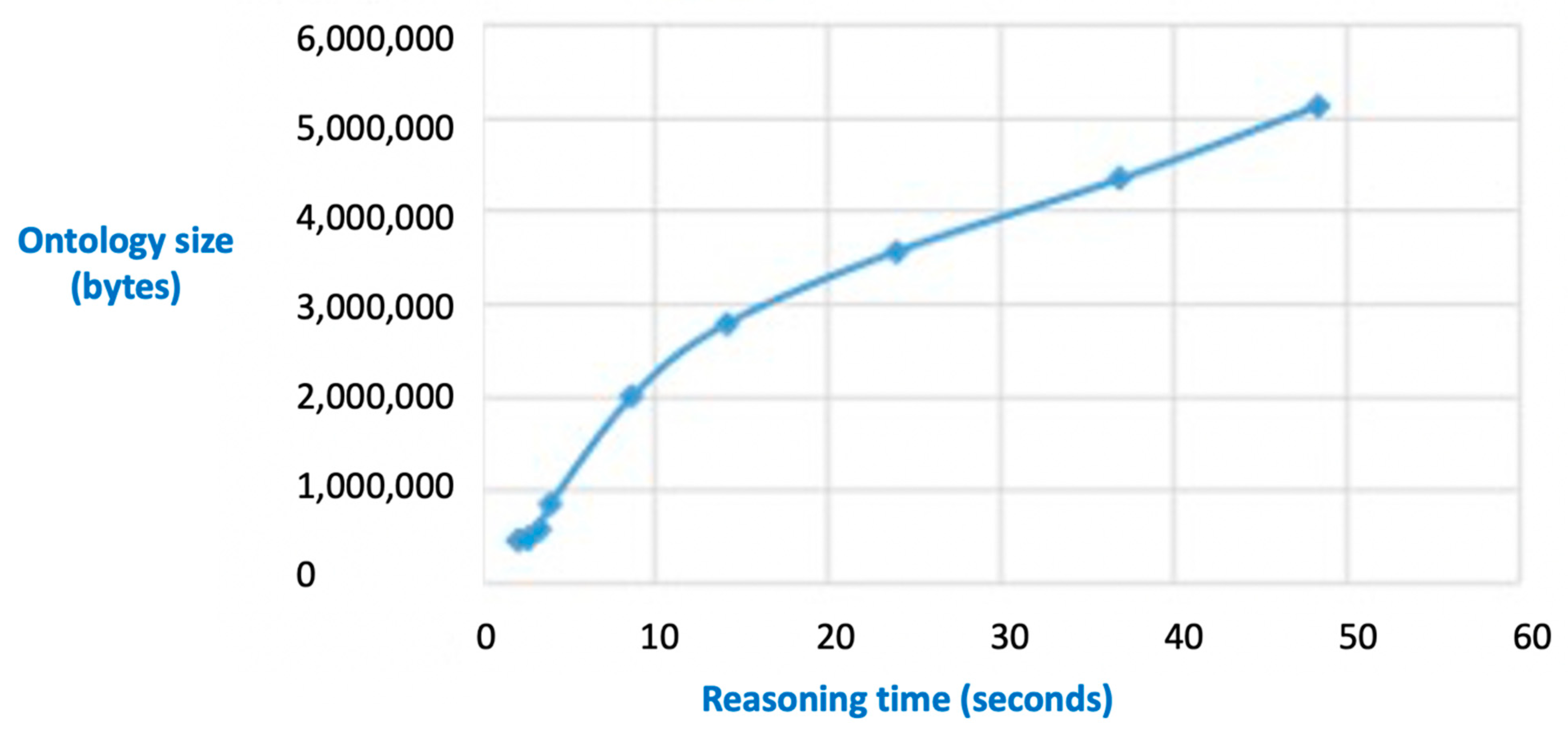
The time taken by the reasoning process versus the size of the ontology when it is loaded into working memory. This test indicates the complexity of time required by the reasoning process.
Figure 10 shows the space required by the ontology when different sizes of raw data are populated into it. The experiment showed that the space required by the ontology is about 25 times more than the size of the raw data on average, and there is a linear relationship between the two variables. For example, from the graph, raw data of size 112 KB (
x-axis) when populated into the ontology required 2800 KB of space (
y-axis, ontology size).
Figure 11 shows the time taken by the reasoner (the reasoning process) is not linear (exponential at the beginning but then starts to flatten) with respect to the size of the ontology when loaded into working memory. For example, from the graph, when the size of the ontology is 2200 KB, the computational time taken is 10ms to achieve run-time diagnostics.
It is important to mention that, in order to evaluate the performance of the ontology fairly and independently (i.e., without the whole ROS-Husky stack), raw sensor data from Husky after the mission was taken into another test PC also running ROS. In this way we separated the ontology from the whole system. Therefore, 10ms for ontology (after populating the data) of size 2200 KB is the pure reasoning time on a standalone PC. When investigating the complexity of the ontology it has to be in bytes as both raw data and ontology at the bottom are measured in bytes.
Table 2 compares (following an approach similar to [
44,
45]) different systems that utilized ontologies. It is not the theme of this paper to discuss the system integration or architectural aspects, but the focus here is on: (1) the semantic relationships and the related automatons that are used for modelling the hardware components and the links between them, (2) the semantic rules for the faults detection, diagnosis, and prognosis (FDDP) feature.
The selected systems in the table have defined concepts related to hardware components for different purposes, mainly hardware configurations. They have not addressed the challenges relating to diagnostic and prognostic modelling. Within the current state of the art, none of the systems provide semantic relationships apart from KNOWROB via its extension SRDL, however, it is a very constrained model relying on very limited semantic relationships, such as Depends-On. This is due to KNOWROB prioritizing the computational demands of models thereby simplifying the knowledge to a shallow level for computational reasons. Therefore, our approach and the modelling paradigm (ORCA-OZO) which is proposed in this paper provides the following contributions: (1) it has strong semantic relationships that are capable of modelling the hardware of different engineering systems (electrical, electronics, communications, control or mechanical), hence, it enables Systems of Systems modelling, (2) the combination of using automata with ontology to support states modelling for safety and reliability assessments, (3) the use of active web semantic rules (SWRL) during the reasoning process supports scalability and integration, (4) the integration of a ontology with ROS components such as ROSPlan to establish a direct relationship with executive operational decisions, and finally (5) the integration of the ontology with a digital twin representation for robot-human collaboration. The integration of these features enables a new capability that can perform faults detection, diagnosis and prognosis (FDDP) onboard during runtime. This capability within an operational run-time is vital to unlock the value of offshore autonomy.
A future work would involve integrating the ontology with offline machine learning algorithms where some rules can be learned and fed back into the ontology. This also help in predictive scheduling and maintenance procedures,
Figure 12.


