Abstract
A statically balanced mechanism is designed as a potential solution for the positioning of surgical instruments. Its kinematics with five degrees of freedom that decouples linear and angular motions is proposed for that objective. The linear motion of its end effector is provided by a classical parallelogram linkage. To enhance its adaptability, a mechanical system allows re-orienting the position mechanism in three different working modes (horizontal, upward and downward) while preserving its static balance. Based on the mechanical concept, a uniformized static balancing condition that considers all working modes is given. The orientation of the end effector is provided by a spherical decoupled mechanism. It generates a remote center of motion which is highly representative of kinematics in surgery requirements. Based on the mechanism kinematics, the evolution of its gravitational potential energy is studied. Two different mechanical concepts are then proposed to generate a compensating elastic potential energy. A CAD model of the entire mechanism has allowed the estimation of all mechanical parameters for the selection of the appropriate tension springs and for carrying out validation simulations. A prototype of the statically balanced mechanism is fabricated and successfully tested.
1. Introduction
While performing some surgical tasks, surgeons often need an instrument to be maintained in a desired position and orientation. Another surgeon will be required to provide this task to assist with the surgery. To suppress the need for medical personnel to hold these instruments for a long period of time, surgical rooms are often equipped with specific mechanical holders. Two types of model appear to be widely used: the first one is a mechanical holding arm the end effector of which can be manually fixed in position by operating a lever that locks all the mechanism joints at once. The second one is a mechanism that can be fixed using a pneumatic system to lock all joints. An example of both kinds of device can be found among products of the AESCULAP company [1]. During surgery, these kinds of arm are operated by unlocking the mechanism, manipulating it into a desired configuration and then re-locking the mechanism joints to maintain both position and orientation.
1.1. Contribution of Statically Balanced Mechanisms
The major issue with these devices is the residual motion observed during the mechanism locking phase. Although the operator can manually position the mechanism very precisely, its accuracy is considerably compromised once the mechanism is locked even without external forces. Mechanism science can potentially generate a solution to this problem. In the case of medical applications that do not require any force interaction with tissues, the problem of the residual motion mentioned above can be solved easily by the use of a statically balanced mechanism (SBM). This particular device has become a specific topic in mechanism science. These fully passive manipulators can be manually operated to move their end effector while their characteristic allows them to automatically compensate the effects of gravity. It is consequently not required to unlock the mechanism before each position adjustments and to re-lock it after, which suppresses the residual motion during the locking phase.
1.2. Static Balancing of Parallelogram Linkages
In 1995, a technique using tension spring to compensate the gravity applied on passive mechanism is introduced. It is dedicated to articulated architectures composed of parallelogram linkages rotating about the horizontal axis [2]. It is shown that each individual parallelogram can automatically compensate its own weight and the weight of following ones. To achieve this characteristic, the appropriate springs attachment points and stiffnesses are calculated so that the elastic potential energy (EPE) evolution can compensate that of the gravitational potential energy (GPE). The total potential energy (TPE) is therefore constant and does not change with the mechanism configuration. This method has been implemented in a pantographic mechanism for a rehabilitation device since 2005 [3]. In this study, three different mechanism linkage concepts are investigated and the respective stiffness of their four springs are determined to compensate for the weight of the patient’s leg. Later, one of these concepts has been used to develop the rehabilitation device [4]. In 2016, a statically balanced mechanism was developed for the manual positioning of an endoscope for surgery [5]. The passive mechanism was composed of two parallelogram linkage for linear positioning and one double pantographic mechanism for orientation. Both parts of the manipulator were statically balanced using zero-free-length tension springs. The same year, a design method based on space mapping was proposed to compensate for the gravity on a parallelogram mechanism [6]. A gravity counter-balance was integrated in another parallelogram mechanism. An additional linkage was attached to it by roll-pitch-yaw spherical wrist. Using a combination of tension springs, cables and pulleys, the parallelogram and the linkage were statically balanced by one spring each [7].
1.3. Static Balancing of Diversified Mechanical Archtitectures
Although parallelogram architectures seem to be widely used in this topic, cases of statically balance mechanisms with other kinds of architecture can be found in the literature. For example, the gravity compensation of a 6-degrees of freedom (DoF) parallel mechanism was reported in 1998. Each leg of the hexapod architecture was composed of one parallelogram linkage followed by one linkage. Each part of one leg was attached with one tension spring [8]. Later in 2000, a study proposed the static balancing of four different parallel mechanisms. They differed from one to another by their leg architectures and their respective gravity compensations were provided by tension springs and/or counterweights [9]. In 2004, a double hexapod architecture was statically balanced using a counterweight ball that was attached to the platform via a pantographic mechanism. This design method allowed the mechanism to maintain a stationary global center of mass [10]. A static balancing manipulator was developed for the ultrasound scanning of blood vessels in 2007. Torsion springs were used on passive and active revolute joints to reduce the motors required torques [11]. In 2010, a study proposed to provide the static balancing of a planar mechanism using non-parallelogram linkage to avoid the singularities and collisions associated with it. The location of the tension spring installation and their parameters were determined by solving the isotropic condition of the stiffness block matrix [12]. Based on this methodology, a 4-DoF planar mechanism was developed in 2012 [13]. The static balancing of a closed-loop planar mechanism with one DoF was performed by integrating two colinear springs [14]. Using a spring-gear concept, a planar mechanism based straight open linkage (instead of parallelogram) was statically balanced [15]. The same design has been used for the static balancing of a Delta mechanism [16].
1.4. Objectives
With the idea of holding and manipulating surgical instruments, the objective of the present work is to design a multidirectional mechanism that is statically balanced. The mechanical architecture will generate a total of 5 DoF for the position and orientation of lightweight instruments. The linear motion will displace the end effector with 3 DoF and the angular motion will orient it with 2 DoF. As statically balanced mechanisms work only for a given direction of the gravity, they can be designed only in a specific orientation. This means that they may not be re-oriented to adapt with a geometrically different environment. In a medical room for example, a passive manipulator may be placed horizontally on the side of the clinical bed or vertically above it. No device is able to comply with both situations so two different manipulators shall be designed for these two cases. In order to increase its adaptability with different medical room organization, the proposed mechanism will offer the possibility of reconfiguration in several working modes in order to enlarge its workspace and change its general direction. This feature remains absent from the literature. A mechanical concept will be proposed for the uniformization of the position mechanism’s static balancing. It will allow the rapid reconfiguration of the mechanism in several working modes. To achieve this goal, the rest of the present document is organized in six Sections. Section 2 describes the mechanism concept and provides its kinematic analysis. Section 3 presents the static balancing of the position mechanism and the concept that ensures a static balancing in all working modes. The static balancing of the orientation mechanism is presented in Section 4. Section 5 will identify the required mechanical parameters and illustrate the mechanism prototype testing. Section 6 provides the conclusion.
2. Kinematics of the Statically Balanced Mechanism
The motion generated by the SBM is defined based on a specific mechanical architecture concept. For the study of any SBM, the understanding of its kinematics is required before proposing a mechanical concept for the static balancing method.
2.1. Definition of the Mechanism Concept
The SBM is required to manipulate a thin tool or instrument with both linear and angular motions. It will have a total of 5 DoF, decoupled between 3 linear DoF and 2 angular DoF. The mechanical concept will rely on a hybrid mechanism. It is composed of two different mechanisms: one mechanism that manage the linear positioning and one mechanism that provides the angular positioning. The first mechanism is a position mechanism that generates the 3 linear DoF. Its main function is to displace the center of rotation of the end effector in a 3-D space. The second mechanism is an orientation mechanism that rotates the end effector around a horizontal two axes. As in many applications such as for the manipulation of instruments in surgical procedures, it shall be more advantageous to use a rotational mechanism that generates a remote center of motion (RCM) as stated in review study on minimally invasive surgery in 2012 [17] or in comparative study for tele-echography in 2014 [18]. Minimally invasive interventions are being standardized due to their advantageous safety. Consequently, the mechanism end effector will be pointing constantly at a center of rotation while rotating around it.
The position and orientation mechanisms mentioned above will be assembled into a hybrid mechanism. The position mechanism will provide linear motion by means of two linkages connected by 3 revolute joints. The two first joints are located between the base and the proximal linkage and their rotation axes are orthogonal. The third revolute joint is located between the first and second linkages. While the second and third joints allow the linkage to move on a plane along 2 linear DoF, the first joint provides the rotation of that plane around an axis passing through the mechanism base. This gives a total of 3 linear DoF. Another functionality of this mechanism is the ability to be re-oriented in order to provide enhanced reachability with a larger workspace. An additional revolute joint with a special locking system will be added to punctually change the global direction of the position mechanism. As shown in Figure 1, there are 3 possible working modes: horizontal, vertical upward and vertical downward.
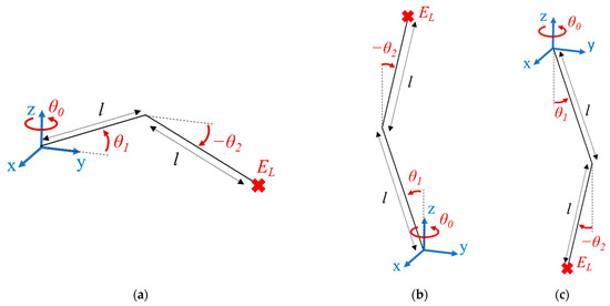
Figure 1.
Possible working modes of the position mechanism: (a) horizontal, (b) vertical upward and (c) vertical downward.
The orientation mechanism is mounted at the end of the position mechanism and is made of a spherical decoupled mechanism (SDM) assembled as a 5-bar spherical linkage. It has been proposed and studied in 2018 as a mechanism that merges the kinematic advantage of decoupled architecture while maintaining a simple design compared to other decoupled mechanisms [19]. In 2020, its optimization into a manipulator for neuro-endoscopy has been reported, which shows that it is well adapted for orienting thin and light instruments [20]. As seen in Figure 2, this mechanism is made of four spherical linkages referred to as A, B, C and D. They are connected via a total of five revolute joints. The linkages A and B are connected to the mechanism base via two of these joints. The point OS is the origin of the reference frame and the location of the center of rotation, where all joint axes are intersecting. The axes xS and yS of the reference frame are, respectively, passing through the first revolute joint of the linkage A and B.
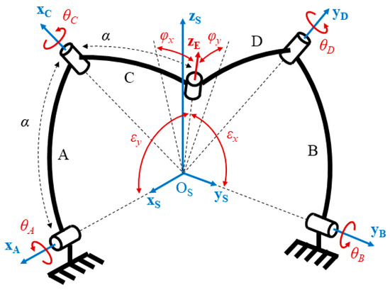
Figure 2.
Mechanical architecture of the orientation mechanism.
In order to simplify both kinematic and static balancing studies, all linkage dimensions are equal and are given by the length l for the position mechanism and the angle α for the orientation mechanism. A general kinematic representation of the 5-DoF SBM is given in Figure 3. It is assumed that the (OSxSyS) plane of the SDM will remain horizontal while being displaced by the position mechanism.
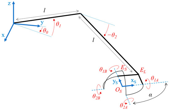
Figure 3.
Kinematic representation of the 5-degrees of freedom (5-DoF) statically balanced mechanism (SBM).
2.2. Kinematic of the Position Mechanism
The kinematic associated with the position mechanism is very simple and can be found through the geometric method. The position of the end effector can be written as a vector of three components, pE = [xE yE zE]T. For the resolution of the forward kinematic model (FKM), the expressions of each component of pE are written with respect of the coordinates of the mechanism’s three revolute joints given by angles θ0, θ1 and θ2. When the position mechanism is locked in horizontal working mode, the FKM can be written as follows:
A parameter that considers the desired working mode of the mechanism can be directly integrated in the kinematic model to obtain a unified model. A locking joint variable θL is integrated. It can take three possible values: 0 for horizontal working mode, π/2 for vertical upward and −π/2 for vertical downward working mode. Although the variable the θ1 could be directly changed by ±π/2, it has been chosen to use this new variable as an anticipation to the definition of the mechanism design presented in Section 3.2. The mechanism unified FKM can be then written by considering that the angles θ0 and θL orient the base of the two parallelogram linkages. The position of the position mechanism end effector is, therefore, written as:
It is developed and written as follows:
where θL is -π/2, 0 or π/2, regarding the mechanism working mode.
2.3. Kinematic of the Orientation Mechanism
One advantage of the SDM is the simplicity of its kinematic model compared to most spherical mechanisms. It can be resolved simply using spherical trigonometry. The resolution method has been treated in previous studies [21]. The FKM of the SDM can be written as follows:
with φx, φy ϵ [−π/2; π/2]. Using Equation (5), the Inverse Kinematic Model (IKM) of the mechanism is obtained by expressing the joint variables θD and θC with respect to the end effector angular coordinates φx and φy.
It is anticipated that studying the static balancing of the SDM will require the joint coordinates θA and θB as well. A previous version of the 5-bar spherical linkage that does not offer decoupled motion has been studied in 2010. In that study, the first joint of each RRR arm was calculated as part of the IKM [18]. These joints correspond to the passive joint of the present SDM. Therefore, their coordinates can be calculated as follows:
By substituting Equation (6) in Equation (7), the expression of the passive joint variables can be written as follows:
Based on the kinematic of the mechanism, the position of all linkages will be known for every configuration. They are required to determine the gravitational potential energy of the mechanism which is calculated using their height.
3. Static Balancing of the Position Mechanism
The mechanical concept is proposed to insure the conservation of the mechanism potential energy in every possible configuration.
3.1. Static Balancing of the Multi-Directional Parallelogram Mechanism
In the case of a horizontal parallelogram as seen in Figure 4a, the expression of the GPE is calculated by simply projecting the position of the center of mass and multiplying it by the gravitational constant g and by the mass of all moving linkages. For each parallelogram, the moving linkages include the distal transversal linkage and the longitudinal ones the synchronized rotation of which is given by the input variable θi (i = 1, 2). The proximal transversal linkage is not included. The tension spring has a stiffness given by the parameter ki and its attachment points on the longitudinal and transversal linkage are given by the parameters li1 and li2 respectively.
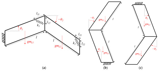
Figure 4.
Parallelogram linkages of the position mechanisms in horizontal (a), upward (b) and downward (c) working modes.
For a parallelogram linkage which configuration is given by the variable θ, the static balancing condition is written as follows:
where ET, EG and EK are the total, the gravitational and the elastic potential energies. Based on the mechanical parameters shown above, the TPE of the second parallelogram can be differentiated with θ2 and assumed to be zero. The variable θ2 can then be eliminated and the spring stiffness that guarantees the static balance in any configuration is written as follows:
The same method is applied to the first parallelogram linkage. The difference is that the mass of the parallelogram linkage coming after must be considered in the GPE since it has to carry it as well. The first spring stiffness is isolated and written with respect to the over mechanical parameters as follows:
3.2. Mechanical Concept for the Uniformization of the Position Mechanism Static Balancing
In order to ensure the position mechanism static balancing in any working mode, it is proposed to add in each parallelogram an adjustment linkage that is oriented from the longitudinal linkage by a parameter depending on the desired working mode. As the mechanism configuration is changing, the elongation of the tension spring attached to it evolves as well. This evolution can be changed by relocking that adjustment linkage into another position regarding the desired working mode of the mechanism. The mechanical concept is illustrated in Figure 5. The rotation of the added linkage can control the mechanism working mode. The angle between this linkage and the longitudinal linkage of the parallelogram mechanism corresponds to the parameter θL. Based on this concept, the elongation of the tension spring is controlled by the angles θi and θL. While θi controls the progressive elongation of the tension spring in a specific working mode, the angle θL defines how the elongation shall evolve. It is noted that in the case of θL = 0, the proposed concept will simulate the architecture of the classical parallelogram in horizontal working mode.
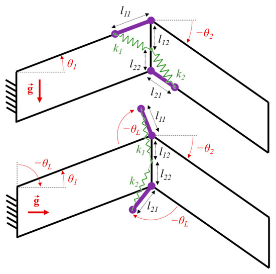
Figure 5.
Mechanical concept for the uniform static balancing of the position mechanism.
According to the mechanical concept illustrated in Figure 5, the elongation of the tension spring can be calculated as follows:
where i = 1 or 2 and θL = −π/2, 0 or π/2 regarding the mechanism working mode. As a result, the EPE of the parallelogram linkage can be calculated as follows:
3.3. Results
Based on the mechanical concept, the EPE and GPE of all linkages can be calculated. It is now possible to determine the spring stiffness with respect to the mechanical parameters to ensure the mechanism static balancing. The study starts with the second linkage which potential energy conservation includes the expression of its EPE and GPE is written down as follows:
By simplification of Equation (14), the required spring stiffness is isolated and its expression is written with respect of the other linkage mechanical parameters as follows:
The same method is applied to the first linkage and the required spring stiffness for the first linkage is isolated and written as follows:
The relationships between the mechanical parameters to ensure the static balancing are known. But these parameters must be determined based on a highly realistic CAD model for a real application case. Indeed, some parameters such as the linkage sizes or masses can only be assumed at this point of the study. Also, the above study does not consider the mass of the orientation mechanism that will be attached to the position mechanism. Its mass should be included in the calculation of the GPE of the linkages. The final parameters considering the presence of the orientation mechanism will be identified in Section 5.
4. Static Balancing of the Orientation Mechanism
According to Gosselin et al., it is possible to statically balance a close chain mechanism using elastic elements, i.e., tension spring [22]. Based on the kinematic of the chosen orientation mechanism, the evolution of its GPE is studied and a mechanical concept is proposed to generate a compensating EPE.
4.1. Evolution of the Gravitational Potential Energy
The evolution of its GPE will be studied for each linkage individually. Therefore, their height must be determined with respect of the mechanism configuration. The moving linkages of the SDM are referenced by the capital letter A to D. Their mass are given by the parameter mK, with K = A, …, D. A moving reference frame is associated to each moving linkage and the coordinates of their respective center of mass are given in these moving reference frames. They are referenced as {xK yK zK}, with K = A, …, D. A series of rotation matrices are then used to calculate these coordinated in the mechanism general reference frame. They will be expressed with respect to the mechanism joint coordinates. According to the mechanism revolute joint locations and curved linkage dimensions, the different rotation motions between the linkage reference frames are shown in Figure 6.
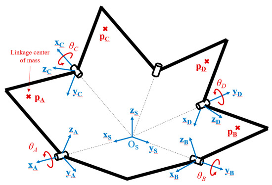
Figure 6.
Reference frames and centers of mass associated to the spherical decoupled mechanism (SDM) linkages.
Based on this kinematics, the position of all linkages center of mass are calculated. In order to simplify the study and the coming design of the mechanism, the parameter α that gives the size of all linkages is set to π/2. The position of their respective center of mass in their own reference frame are given by the coordinates ux, uy and uz (with u = a, b, c, d). As the linkage A is rotating around axes x (or xA), the position of its center of mass pA is described as one rotation around the x axis of angle θA given by Rx(θA) and written as:
and for the linkage B, as one rotation around the y axis of angle θB given by Ry(θB), it is written as:
The center of mass coordinates for the linkage C can be calculated for each linkage as one rotation around x axis of angle θA given by Rx(θA), one rotation of −π/2 around z axis given by Rz(π/2) and one rotation around x axis of angle θC given by Rx(θC). The coordinates are, therefore, calculated as follows:
Based on a very similar kinematics, the position of the center of mass for linkage D is written as:
For the calculation of their respective GPE, the height of linkages A, B, C and D, respectively given by pA(3), pB(3), pC(3) and pD(3) will be, respectively, noted hA, hB, hC and hD. They are all regrouped in the vector h = [hA hB hC hD]T and the linkage masses are regrouped in the vector m = [mA mB mC mD]T. Therefore, the total GPE of the SDM can be written as follows:
4.2. Mechanical Concepts for the Orientation Mechanism Static Balancing
In order to ensure the static balancing of the SDM, the GPE of each linkage must be individually compensated for by their EPE, which means that each SDM linkage must be embedded with a mechanical design that elongates a tension spring appropriately while their configurations are changing. One simple solution to generate such an elongation is to design the linkages A and B as parallelogram linkages like for the position mechanism. The drawing of the conceptual design is shown on Figure 7 taking the example of linkage B. They are made of two parallel linkages that present a right angle separating two straight sections. While the distal sections of both linkages form a rectangle, the proximal sections of both linkages form a parallelogram architecture with the same kinematic as those of the position mechanism. In the present design, this parallelogram is used to accommodate the tension spring that is elongated in the same way as the horizontal parallelogram. The same concept is used for linkage A.
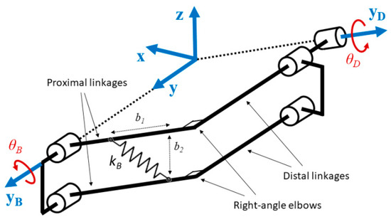
Figure 7.
Conceptual design of the static balancing for the SDM first linkage.
According to the above mechanical design concept, the elongation of the springs on linkage A and B are simply calculated using the same method as for the parallelogram linkage. Their respective elongations eA and eB are calculated below:
and their respective EPE can be written as follows:
The GPE evolution of the linkages C and D is more complex as it depends on two angles at the same time. A mechanical concept illustrated in Figure 8 is proposed for the elongation of the spring. The linkage D is taken as an example. While this linkage is oriented by the angles θB and θD, the parallelogram design of the linkage B allows it be connected to a platform the orientation of which remains unchanged.
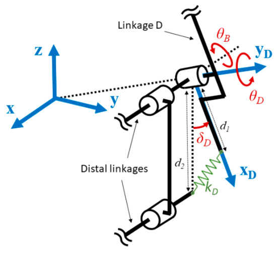
Figure 8.
Conceptual mechanism for the elongation of the SDM second linkage.
Based on the above mechanical concept, the rotation of the linkage C generates an elongation calculated as follows:
where δC is the angle between the longitudinal axis of the linkage C given by the axis yC and the vertical axis passing through its center of rotation. Based on the mechanical concept shown in Figure 8 and on the kinematic associated with the second linkage of each arm, the projection given by angle δC can be replaced by a projection given by the angles θA and θC. Therefore, Equation (25) can be written as follows:
The elongation obtained is used to calculate the EPE of the linkage C as:
Since the SDM is a symmetric mechanism, the linkage D that is designed the same way will generate a similar elongation. The same method is used for the linkage D to calculate the elongation and to integrate it in the EPE formula as follows:
4.3. Results
Once the mechanical concept has been defined to ensure the static balance of the mechanism, the objective is to determine the mechanical parameters required to satisfy the potential energy preservation for any configuration. The linkages A and B show a concept very similar with the classical parallelogram linkage. Based on Equations (16) and (23), the total potential energy of the linkage A is developed as follows:
The simplification of Equation (32) allows isolating the required spring stiffness and writing its expression with respect to the other linkage mechanical parameters as follows:
The method can be applied to the linkage B to isolate the required spring stiffness for the linkage B as follows:
To determine the mechanical parameter required for the static balancing of the linkages C and D, the method used above is also applied. For the linkage C, the following potential energy conservation formula is written as:
The expression of the spring stiffness can be isolated as follows:
Using the same method, the potential energy conservation formula is written and the spring stiffness expression for the linkage D is obtained as below:
Based on the spring stiffnesses given above, it is possible to ensure the SDM static balancing by adjusting all the mechanism mechanical parameters accordingly to Equations (31)–(35). However, some of these parameters (masses, sizes, etc.) cannot be determined without a preliminary prototype or at least a realistic CAD model.
5. Mechanical Design of the Statically Balanced Mechanism
The formula of all spring stiffness to ensure the mechanism static balancing have been calculated in Section 3 and Section 4. The relationships between the different mechanical parameters to respect the potential energy conservation are all known. In order to determine them numerically for the design and fabrication of an actual prototype, a realistic CAD model must be used to simulate some parameters (such as the mass) and to adjust some others (such as the spring attachment points).
5.1. Design of the Mechanism Prototype
The kinematic drawing of the mechanism presented in Figure 3 has been used as a reference for the design of a realistic CAD model on Solidworks. The general linkage size parameters of the mechanism are illustrated on the CAD model in Figure 9.
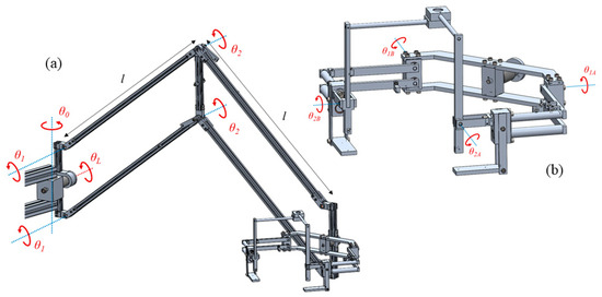
Figure 9.
CAD model of the multidirectional statically balanced mechanism. Joint variables of the position (a) and orientation (b) mechanism.
As shown in Figure 10, the change of working mode is done by manually rotating the adjustment linkage in the appropriate direction given by the parameter θL. A mechanical system using a compression spring and positioning pins allows locking the adjustment linkage by pulling, rotating and releasing. The same concept is used to lock the base of the mechanism in the appropriate orientation. The spherical mechanism can be also re-oriented and locked to maintain its (OSxSyS) horizontal plan in any working mode using the same design.
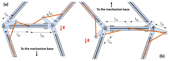
Figure 10.
Adjustment linkage operating for the vertical upward (a) and downward (b) working modes.
5.2. Identification of the Mechanical Parameters
Based on the CAD model, all mechanical parameters of the mechanism used for the static balancing study are given in Table 1 for the position mechanism and in Table 2 for the orientation mechanism.

Table 1.
Mechanical parameters of the position mechanism.
Table 2.
Mechanical parameters of the orientation mechanism.
All identified parameters are used to calculate the tension spring stiffness required for the mechanism static balancing. For each linkage of the orientation mechanism, the required parameters are used in Equations (31)–(35). The theoretical spring stiffnesses are obtained and displayed in Table 3. However, available springs in the market do not necessarily offer the same values. Therefore, each spring is selected with a stiffness as close as possible. The stiffnesses of the real springs are displayed in Table 3 as well.
Table 3.
Tension spring stiffnesses for the orientation mechanism.
Since the spring stiffnesses have changed, the mechanical parameters involved in their expression must be changed as well to ensure the static balancing. It would be very difficult to change the mass of the linkages or the coordinates of their center of mass, so it is chosen to recalculate the attachment point of the tension springs. These modifications are displayed in Table 4 and the CAD model has been refined based on these new parameters. The resulting changes of mass and center of mass are considered negligible.
Table 4.
Refined mechanical parameters for the orientation mechanism.
The same principle is applied for the position mechanism. The theoretical stiffnesses can be calculated from Equations (14) and (15). However, the mass of the orientation mechanism, mS = 815.47 g, will be considered this time. The new stiffness expressions are given as follows:
These new stiffnesses and those of the commercially available springs are displayed in Table 5.
Table 5.
Tension spring stiffnesses for the position mechanism.
The parameters associated with the position of the spring attachment points are refined in Table 6. Based on the present design shown in Figure 10, the parameters l12 and l22 can be manually adjusted by relocating and tightening the spring attachment point on the transversal frame.
Table 6.
Refined mechanical parameters for the position mechanism.
5.3. Simulation and Prototype Testing
Based on the numerical values of the mechanical parameters identified in Section 5.2, a series of simulation is performed in order to verify that the static balancing of the mechanism is theoretically correct. The data in Table 1, Table 5 and Table 6 are used to display the evolution of the TPE, the GPE and the EPE of the entire position mechanism (considering the mass of the orientation mechanism) for any configuration given by θ1 and θ2. These energies are displayed for the three different working modes: horizontal in Figure 11, vertical upward in Figure 12 and vertical downward in Figure 13. All these graphics show that the conservation of the total potential energy is confirmed for any mechanism configuration of any working mode. Which proves the efficiency of the proposed mechanism concept for the uniformization of static balancing.
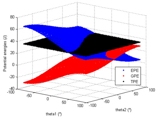
Figure 11.
Evolution of the position mechanism potential energies in horizontal working mode.
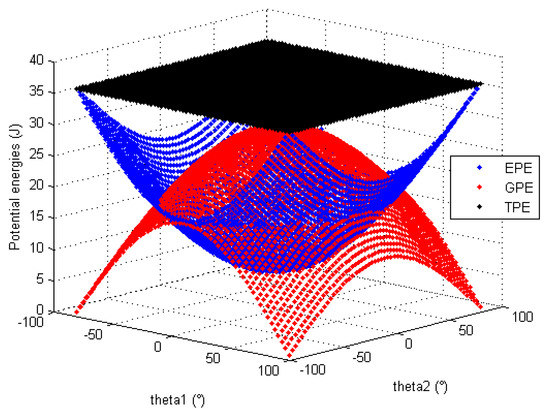
Figure 12.
Evolution of the position mechanism potential energies in vertical upward working mode.
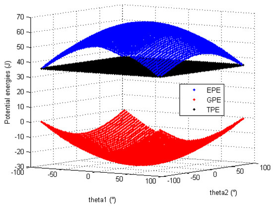
Figure 13.
Evolution of the position mechanism potential energies in vertical downward working mode.
The same simulations are performed on the orientation mechanism. The data provided in Table 2, Table 3 and Table 4 are used to the study the evolution of the total potential energy of each SDM linkage. The evolution of the TPE, GPE and EPE for the linkage A, B, C and D are, respectively, displayed in Figure 14 and Figure 15. It is noted that the potential energies of linkages C and D depend on two variables.
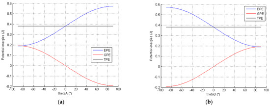
Figure 14.
Evolution of the potential energies of the SDM linkage A (a) and linage B (b).
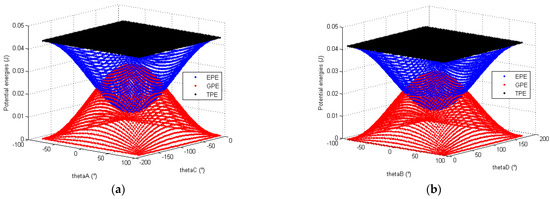
Figure 15.
Evolution of the potential energies of the SDM linkage C (a) and linkage D (b).
The CAD model of the entire mechanism was used to manufacture a 5-DoF SBM. The prototype was mounted and tested by manipulating it in several configurations. The position mechanism was tested with the spherical mechanism mounted at its end. It can be seen in Figure 16 and Figure 17 that it is able to hold itself while supporting the orientation mechanism in any position.
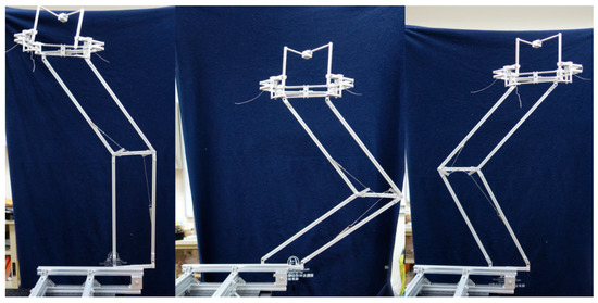
Figure 16.
Prototype of the SBM in several configurations in vertical upward mode.
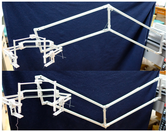
Figure 17.
Prototype of the SBM in several configurations in horizontal mode.
The orientation mechanism has been also tested by displacing its end effector in several orientations. It is shown in Figure 18 that the mechanism will conserve its orientation in any configuration.
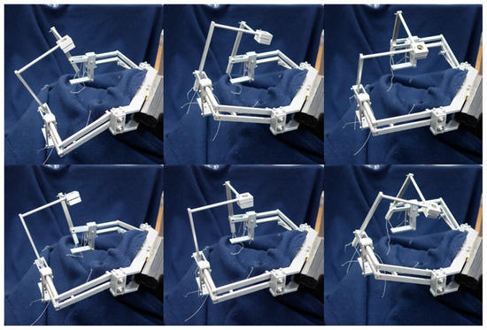
Figure 18.
Prototype of the statically balanced SDM in several configuration for testing.
5.4. Limitations and Potiential Persectives
A series of tests illustrated in the previous section has shown that the SBM can successfully maintain its balance in several working modes. A new device for medical purposes based on the present concept has promising potential as it can adapt to a medical room with different environment geometry. While using the manipulator, some observations have been made. First, it is noted that according to the above study, the static balancing of this manipulator does not consider the mass of an instrument it would carry in an operation. This can be done easily by adding the mass to the orientation mechanism. However, such mass shall be fixed and the manipulator may not be able carry lighter or heavier objects. The design of a new SBM that could reconfigure its spring attachment position to comply with variable payload may be an interesting perspective. Another feedback from the experiments is the necessity of operating two different adjustment linkages when changing the mechanism working mode as shown in Figure 5. The design of a transmission system that automatically operated all required devices by operating only one part of the mechanism would be also an interesting design improvement.
6. Conclusions
In the present work, a statically balanced mechanism has been designed. Its kinematics provide a total of 5 DoF: 3 linear DoF and 2 angular DoF. Its mechanical architecture decouples the linear position from the angular position. It is made of two different mechanisms. One is a combination of two parallelogram linkages, which is a classical architecture for statically balanced mechanisms. However, it is integrated with a specific mechanical concept that ensures the static balancing in any working mode: horizontal, upward and downward. Based on that concept, the potential energy conservation applied to this mechanism has been uniformized in order to identify the appropriate mechanical parameters. This allows the entire mechanism to be adapted in three different orientations, which eliminate the need for one manipulator for each situation. The orientation mechanism is made of a spherical decoupled mechanism that orients the end effector around a fixed point. Its static balancing is ensured by a mechanical concept that generates the appropriate spring elongation with two different angles. A realistic CAD model has been made, which has permitted the estimation of all mechanical parameters associated with the mechanism static balancing conditions. Based on these data, a series of simulations have been performed to demonstrate the theoretical results of the proposed mechanical concepts. A prototype has been fabricated and has been successfully tested, and it can preserve its balance is all positions and orientations and in all working modes.
Funding
This research received no external funding.
Institutional Review Board Statement
Not applicable.
Informed Consent Statement
Not applicable.
Data Availability Statement
Data sharing not applicable.
Conflicts of Interest
The author have no conflict of interest to declare.
References
- Kim, S.-J.; Lee, S.-C. Technical and Instrumental Prerequisites for Single-Port Laparoscopic Solo Surgery: State of Art. World J. Gastoenterol. 2015, 21, 4440–4446. [Google Scholar] [CrossRef] [PubMed]
- Rahman, T.; Ramanathan, R.; Seliktar, R.; Harwin, W. A Simple Technique to Passively Gravity-Balance Articulated Mechanisms. ASME J. Mech. Des. 1995, 117, 655–658. [Google Scholar] [CrossRef]
- Agrawal, A.; Agrawal, A.K. Design of Gravity Balancing Leg Orthosis Using Non-zero Free Length Springs. Mech. Mach. Theory 2005, 40, 693–709. [Google Scholar] [CrossRef]
- Banala, S.K.; Agrawa, S.K.; Fattah, A.; Krishnamoorthy, V.; Hsu, W.-L.; Scholz, J.; Rudolh, K. Gravity-Balancing Leg Orthosis and Its Performance Evaluation. IEEE Trans. Robot. 2006, 22, 1228–1239. [Google Scholar] [CrossRef]
- Kuo, C.-H.; Lai, S.-J. Design of a Novel Statically Balanced Mechanism for Laparoscope Holders with Decoupled Positioning and Orientating Manipulation. ASME J. Mech. Robot. 2016, 8. [Google Scholar] [CrossRef]
- Cho, C.-H.; Lee, W. Design of a Static Balancer with Equivalent Mapping. Mech. Mach. Theory 2016, 101, 36–49. [Google Scholar] [CrossRef]
- Chen, Y.; Liu, Y.; Li, C.; Liu, G.; Zhu, Y.; Zhao, J.; Cai, H. Gravity Balance Mechanism for a Spatial Robotic Manipulator. J. Mech. Sci. Technol. 2016, 30, 865–869. [Google Scholar] [CrossRef]
- Gosselin, C.M.; Wang, J. On the Design of Gravity-Compensated Six-Degree-of-Freedom Parallel Mechanisms. In Proceedings of the IEEE International Conference of Robotics and Automation, Leuven, Belgium, 16–20 May 1998; Volume 3, pp. 2287–2294. [Google Scholar]
- Wang, J.; Gosselin, C.M. Static Balancing of Spatial Four-Degree-of-Freedom Parallel Mechanisms. Mech. Mach. Theory 2000, 35, 563–592. [Google Scholar] [CrossRef]
- Russo, A.; Sinatra, R.; Xi, F. Static Balancing of Parallel Robots. Mech. Mach. Theory 2005, 40, 191–202. [Google Scholar] [CrossRef]
- Lessard, S.; Bigras, P.; Bonev, I.A. A New Medical Parallel Robot and its Static Balancing Optimization. ASME J. Med. Devices 2007, 1, 272–278. [Google Scholar] [CrossRef]
- Lin, P.-Y.; Shieh, W.-B.; Chen, D.-Z. A Stiffness Matrix Approach for the Design of Statically Balanced Planar Articulated Manipulators. Mech. Mach. Theory 2010, 45, 1877–1891. [Google Scholar] [CrossRef]
- Lin, P.-Y.; Shieh, W.-B.; Chen, D.-Z. Design of Statically Balanced Planar Articulated Manipulators with Spring Suspension. IEEE Trans. Robot. 2012, 28, 12–21. [Google Scholar] [CrossRef]
- Jhuang, C.-S.; Kao, Y.-Y.; Chen, D.-Z. Design of one DOF closed-loop statically balanced planar linkage with link-collinear spring arrangement. Mech. Mach. Theory 2018, 130, 301–312. [Google Scholar] [CrossRef]
- Nguyen, V.L.; Lin, C.-Y.; Kuo, C.-H. Gravity Compensation Design of Planar Articulated Robotic Arms Using the Gear-Spring Modules. ASME J. Mech. Robot. 2020, 12. [Google Scholar] [CrossRef]
- Nguyen, V.L.; Lin, C.-Y.; Kuo, C.-H. Gravity compensation design of Delta parallel robots using gear-spring modules. Mech. Mach. Theory 2020, 154, 104046. [Google Scholar] [CrossRef]
- Kuo, C.-H.; Dai, J.S.; Dasgupta, P. Kinematic Design Considerations for Minimally Invasive Surgical Robots: An Overview. Int. J. Med. Robot. Comput. Assist. Surg. 2012, 8, 127–145. [Google Scholar] [CrossRef] [PubMed]
- Essomba, T.; Laribi, M.A.; Nouaille, L.; Zeghloul, S.; Poisson, G.; Vieyres, P. A specific performances comparative study of two spherical robots for tele-echography application. Proc. Inst. Mech. Eng. Part C J. Mech. Eng. Sci. 2014, 228, 3419–3429. [Google Scholar] [CrossRef]
- Essomba, T.; Nguyen, V.L. Kinematic Analysis of a New Five-Bar Spherical Decoupled Mechanism with Two-Degrees of Freedom Remote Center of Motion. Mech. Mach. Theory 2018, 119, 184–197. [Google Scholar] [CrossRef]
- Essomba, T.; Nguyen Vu, L.; Wu, C.-T. Optimization of a Spherical Decoupled Mechanism for Neuro-Endoscopy Based on Experimental Kinematic Data. J. Mech. 2020, 36, 133–147. [Google Scholar] [CrossRef]
- Wu, C.; Liu, X.-J.; Wang, L.; Wang, J. Optimal Design of Spherical 5R Parallel Manipulators Considering the Motion/Force Transmissibility. ASME J. Mech. Des. 2010, 132. [Google Scholar] [CrossRef]
- Gosselin, C. Static Balancing of Spherical 3-DOF Parallel Mechanisms and Manipulators. Int. J. Robot. Res. 1999, 18, 819–829. [Google Scholar] [CrossRef]
Publisher’s Note: MDPI stays neutral with regard to jurisdictional claims in published maps and institutional affiliations. |
© 2021 by the author. Licensee MDPI, Basel, Switzerland. This article is an open access article distributed under the terms and conditions of the Creative Commons Attribution (CC BY) license (http://creativecommons.org/licenses/by/4.0/).