Abstract
In this paper, we explore the Larmor time for three types of trapezoidal barriers, and we find consistent results between the traditionally defined Larmor time and a newly defined one. We confirm that the transmission Larmor time for the trapezoidal barriers also satisfies certain properties of mirror-symmetric barriers. Consistent with our expectations, we also find that: 1. as the barrier height increases, the peak of the Larmor time shifts to the right (higher energy); and 2. as the barrier width increases, the peak becomes larger in coincidence with the classical expectation that a particle needs more time to cross a longer path of the same height/inclination.
1. Introduction
Quantum tunneling, as a purely quantum effect, plays a crucial role in various fields such as nuclear physics [1,2], semiconductor devices [3,4], chemical reaction kinetics [5], and Hawking radiation [6]. Since MacColl posed the question of how long a particle tunnels through a given barrier in 1932 [7], the tunneling time has remained a controversial issue. In the theoretical framework of quantum mechanics, time only serves as a parameter describing the evolution of a system and is not an observable mechanical operator. Consequently, it is difficult to obtain a clear, definite, and widely accepted answer to the problem of quantum tunneling time. Currently, many definitions of tunneling time have been widely discussed, such as Eisenbud–Wigner time delay (also known as phase time) [8,9,10], dwell time [11], and Larmor time [12,13,14].
Discussions on the Larmor time have greatly promoted people’s understanding and research on the tunneling process. The Larmor time utilizes the Larmor precession of a particle’s spin in a magnetic field as a “clock” to measure the duration of the tunneling process. This innovative idea was first proposed by Baz [12,13] and subsequently applied by Rybachenko [14] for the measurement of tunneling time. Building upon prior research of the Larmor time, our group has proposed a similar idea to employ a novel configuration of particle spin, propagation, and magnetic field directions [15,16]. In recent years, attosecond experiments have drawn more attention to quantum tunneling time [17], and experiments with Bose–Einstein condensates of ultracold atoms have demonstrated the feasibility of Larmor time measurement schemes [18,19]. Meanwhile, research on quantum tunneling dynamics in trapezoidal barriers has been gaining increasing attention [20]. Barriers in practical devices (e.g., metal–insulator–metal junctions [21]) tend to manifest as trapezoidal configurations under operational conditions, and research on such structures is fundamentally important for revealing genuine physical mechanisms and optimizing device performance. In this paper, we present the results of the Larmor time for general trapezoidal barriers, and the results are found to be consistent for the two definitions of Larmor time.
The rest of this paper is organized as follows. In Section 2, we will take a trapezoidal barrier as an example to provide a brief introduction to the tunneling process. In Section 3, we will present the formulas for the two Larmor times under different configurations, displayed through the figures of Larmor time versus wave number for the three barriers discussed in this paper, and provide a brief analysis on the consistency issues and the anti-intuitive features of tunneling time, the latter of which is shared for other tunneling time definitions, such as phase time. Finally, we summarize our research findings in Section 4.
2. Basic Theory
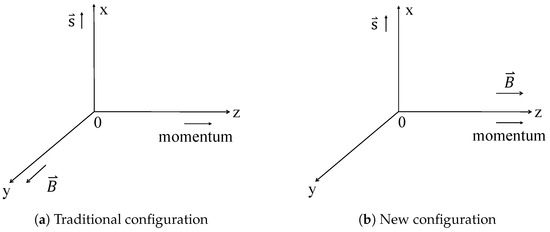
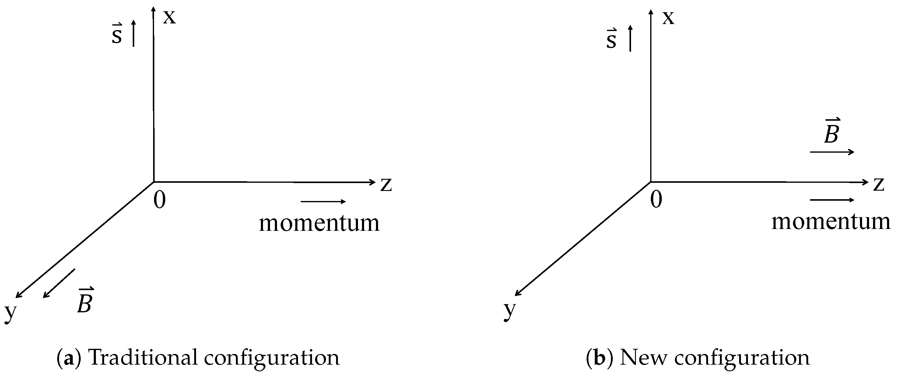
Larmor time is defined for a spinning particle in a magnetic field. Specifically, when a particle traverses a constant magnetic field, its spin rotates around the field direction, a phenomenon known as Larmor precession. The tunneling time is defined as the ratio of the accumulated precession angle in the barrier region to the particle’s angular velocity. Two configurations are commonly used: 1. the traditional configuration with a magnetic field perpendicular to the motion direction [22]; and 2. the configuration in [15], where is parallel/antiparallel to the transmitted/reflected particle’s momentum. As shown in Figure 1, both configurations feature initial spin orientations perpendicular to the magnetic field. To avoid notational conflicts, these will be referred to as the “Baz–Rybachenko–Büttiker (B) [12,14,22]” and “Xiao–Zheng–Liu (X) [15]” configurations.

Figure 1.
The well-discussed traditional configuration (a) and our new configuration (b) of Larmor times; in both subfigures refer to the initial spin orientation.
For a spinning particle tunneling through a barrier , the corresponding Schrödinger–Pauli equation is
In this paper, we will calculate the Larmor time for three types of general trapezoidal barriers and present the corresponding variations of Larmor time with wave numbers. The barrier models are shown in Figure 2. The trapezoidal barrier on the left can be seen as a composite structure, combining a right-angled triangular barrier with a positive slope and a rectangular barrier. For brevity, we refer to it as the trapezoidal barrier. Similarly, the barrier in the middle is named the trapezoidal barrier, while the one on the right is labeled the trapezoidal barrier. Particles are incident in the region . The magnetic field region required for Larmor precession lies between two dashed lines; that is, timing starts when entering the magnetic field region. To calculate the reflection Larmor time, it is necessary to extend the magnetic field region to the left of the barrier. The precession in the left magnetic field region serves as the carrier of the “path information” of the reflected particles, that is, it provides a reflection region for the reflection process; thus, the left boundary of the magnetic field here is b. When calculating the transmission Larmor time, we directly set . This region is not helpful for the calculation of the transmitted Larmor time. The core reason for the Larmor clock is to utilize the precession of spin in a magnetic field as a time probe, and its physical validity depends on the weak field approximation [22], i.e., the perturbation of the magnetic field on the particle’s wavefunction is negligible, which also indicates that Larmor time is essentially a result from weak measurement [23,24]. In the calculations of this paper, an extremely weak magnetic field of = 1 mG is adopted to ensure that this condition holds strictly, so that the spin acts only as a passive probe without altering the nature of scattering.

Figure 2.
The barriers discussed in this paper. The (a) is a trapezoidal barrier, the (b) is an trapezoidal barrier, and the (c) is a trapezoidal barrier form.
Take the trapezoidal barrier as an example. The trapezoidal barrier can be represented as , respectively, where is the slope. The scattering solution for tunneling through a trapezoidal barrier is given below,
where . For the traditional configuration, , and for the new configuration, . Furthermore, similarly to Ref. [16], the wave number , , and . Characteristic length scales are also introduced, defined as and , as well as the corresponding dimensionless wave numbers and . Here, both and refer to the absolute values of the slopes of the triangular barrier regions among the three types of trapezoidal barriers. Specifically, corresponds to the region with a positive slope, while corresponds to the region with a negative slope. For trapezoidal barriers, we have
Starting from Equation (2), similar to the solution to the tunneling problem of a one-dimensional square barrier [25], we can establish the continuity equations and then solve for the specific forms of the transmission () and reflection () amplitudes using the transfer matrix method [26]. The subscripts 1 and 2 in the transmission and reflection amplitudes correspond to the spin-up and spin-down states, respectively. The terms , , , , , and are wave number-dependent amplitudes.
The spin state of a particle polarized along the polar and azimuthal angles direction can be represented as [25]
In both configurations, the initial spin direction is along the x-direction, i.e., and . The relation between the spin orientation and the transmission/reflection amplitudes is given as
Through the relationship between the deflection angle, angular frequency generated by spin precession before and after tunneling, and the tunneling time, we have
where can be or , representing the transmission or reflection amplitude. Meanwhile, g and are the Lande g-factor and the nuclear magneton. Therefore, by substituting the transmission or reflection amplitudes of different barriers, we can obtain the transmission and reflection tunneling times corresponding to the two configurations.
3. The Larmor Time for Trapezoidal Barriers
In this section, we will discuss the aforementioned trapezoidal barrier models. Here, we present the formulas for Larmor time under and barriers. The Larmor time formulas for the more complex barriers, which are based on combinations of the previous two types, will not be detailed here. Meanwhile, we present the figures depicting the variation of Larmor time with the wave number for two configurations.
3.1. The Trapezoidal Barrier
For a trapezoidal barrier, by solving the continuity equation derived from Equation (2) to obtain the transmission/reflection amplitudes and then substituting these into Equations (6) and (7), we can derive the Larmor times for the traditional configuration as follows
while the corresponding Larmor times for the new configuration are then given by
To make the above equations as compact as possible, we have also introduced
where , , , and in the above formulas are also used in the calculation of triangular barriers and are
The forms of and are as follows
The forms in the definitions of various functions adopt similar definitions as those in Ref. [16]. Figure 3 shows the variation of Larmor time with wave number for the trapezoidal barrier. Different barrier heights are selected for comparison. Under the selected barrier parameters, it can be observed that the transmission Larmor time exhibits almost no oscillation, while the reflection Larmor time oscillates. Both show an overall trend of increasing first and then decreasing with the wave number. Furthermore, as the height of the barrier increases, the wave number corresponding to the peak tunneling time also increases. In addition, the results shown by the solid and dashed lines in the figure are consistent, indicating that the Larmor times for the two configurations we discussed are almost indistinguishable for the trapezoidal barrier.

Figure 3.
The figure of transmission and reflection Larmor times versus wave number for the trapezoidal barrier.
3.2. The Trapezoidal Barrier
Similarly, for an trapezoidal barrier, the Larmor times for the traditional configuration are
while the corresponding Larmor times for the new configuration are then given by
To make the above equations as compact as possible, we have also introduced
the forms of , and , are as follows
where , , , and in the above formulas are defined the same as before. The forms of can also be found in Ref. [16]. Figure 4 shows the variation of Larmor time with wave number for the trapezoidal barrier. Different barrier heights are also selected for comparison. Interestingly, the transmission Larmor time is basically consistent with the results under the trapezoidal barrier, which aligns with the mirror-symmetric characteristics of triangular barriers [16]. This phenomenon can be explained by the theorem stating that the transmission amplitudes are identical for mirror-symmetric one-dimensional barriers [27]. Furthermore, as the height of the barrier increases, the wave number corresponding to the peak tunneling time also increases, which is consistent with the previous analysis. Similarly, the results of the Larmor time for the two configurations we discussed are also consistent for the trapezoidal barrier.

Figure 4.
The figure of transmission and reflection Larmor times versus wave number for the trapezoidal barrier.
3.3. The Trapezoidal Barrier
For a trapezoidal barrier, the calculation of the Larmor time still needs to start from Equations (6) and (7). The formula under the trapezoidal barrier is similar to the previous two barrier formulas but more complex; the specific process will not be provided here.
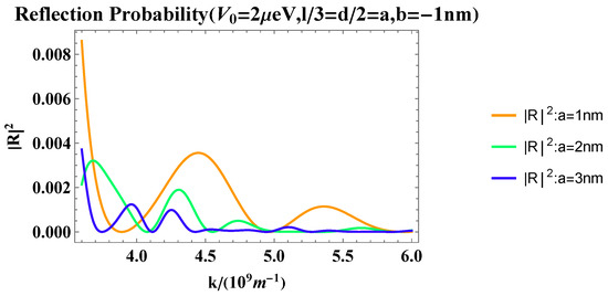
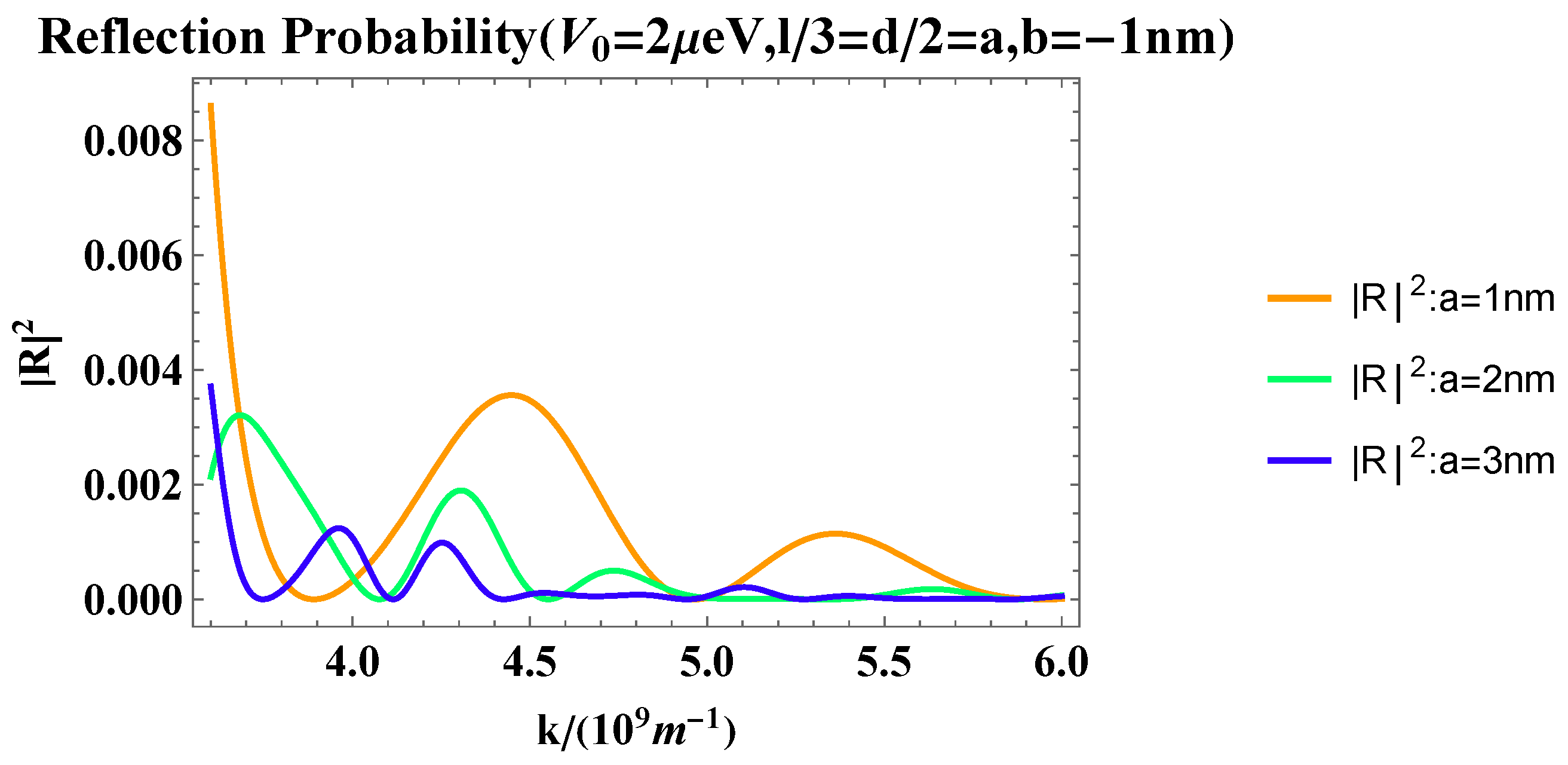
Here, we directly show the results of the variation of Larmor time with wave number for the trapezoidal barrier. We select the same barrier height, keep the proportion of the three parts of the trapezoidal barrier unchanged, and change the overall barrier width for comparison. Figure 5 shows that as the overall width of the barrier increases, the wave number corresponding to the peak of the transmission Larmor time only changes by a little, while the peak intensity increases with the increase in the barrier width. The oscillation of the reflection Larmor time is more pronounced. As the wave number increases, there are a series of “sharp jumps” (discontinuities) in the reflection Larmor time. These “sharp jumps” arise from the flaws in the definition of Larmor time itself. The wave numbers at which these jumps occur coincide with those for local minima of reflection probability in narrow intervals. The reflection probability versus wave number is shown in Figure 6. To demonstrate the precise correspondence between the jumps and the reflection probability, we take the case of a = 1 nm as an example and create Table 1 for further illustration. The results in Table 1 show that the wave numbers corresponding to the minimum values found in the reflection probability indeed coincide with those at the jump positions within the given precision. We argue that at these wave numbers, the reflection probability is nearly 0, and the ratio () changes significantly around 1, which leads to the occurrence of jumps in the reflection Larmor time.

Figure 5.
The figure of transmission and reflection Larmor times versus wave number for trapezoidal barrier.

Figure 6.
The figure of reflection probability versus wave number for trapezoidal barrier.

The results of the Larmor time under the two configurations we discussed are also consistent under the trapezoidal barrier, meaning that the Larmor time results for the two configurations are consistent for all three types of barriers discussed in this paper. Additionally, it should be noted that in the reflected Larmor times of both trapezoidal barriers and trapezoidal barriers, negative values appear in the large wave number range. In fact, similar phenomena can also be observed in triangular barriers with negative slopes (see Ref. [16]). These negative reflection times are a hallmark of quantum interference effects and are closely related to the framework of weak measurements [28,29]. Within the weak measurement framework, the interplay of post-selection and complex probability amplitudes enables the quantum-averaged traversal time (derived from spin precession) to exceed the observable’s eigenvalue spectrum bounds [23,24].
4. Conclusions
In this paper, we present the Larmor time results for three types of barriers (see Figure 2) and show the specific formulas for the Larmor time under the two configurations of and trapezoidal barriers. We find that the transmission Larmor time under trapezoidal barriers also exhibits certain properties of mirror-symmetric barriers. The oscillation of the reflection Larmor time is more pronounced. The results under the two configurations of trapezoidal barriers are also consistent. This indicates that Larmor precession is independent of the relative orientation between the direction of motion and the direction of the magnetic field, highlighting the intrinsic consistency of Larmor time as a measure of tunneling time. After all, the results from both configurations are outcomes of Larmor spin precession (where the spin deflects within the plane perpendicular to the magnetic field). Such results well reflect that the Larmor clock scheme can effectively map the time spent by particles in the barrier region. It can also be seen from the formulas presented in this paper that the calculation for our newly defined configuration is more concise.
Under and trapezoidal barriers, as the barrier height increases, the peak of the Larmor time shifts to a larger wave number (and hence higher energy). Under trapezoidal barriers, as the barrier width increases, the peak of the Larmor time becomes larger. The variation of the peak of the Larmor time with the barrier width and height is consistent across the three types of trapezoidal barriers, i.e., as the barrier height increases, the peak shifts to larger wave number (and hence higher energy) in the figures, and as the barrier width increases, the peak becomes larger. This is understandable. After all, larger barriers naturally require more energy to penetrate, thus causing the peak to shift toward larger k values. Moreover, as the barrier width increases—meaning the obstacle becomes thicker—the required tunneling time naturally becomes longer; thus, the peak values correspondingly increase. There is an obvious peak in the transmitted Larmor time for all three types of barriers, and this peak usually appears near [22]. This phenomenon is similar to the result observed in rectangular barriers. When the particle energy approaches the barrier height, the wave function transitions from exponential decay to oscillatory propagation with increasing energy. This results in drastic phase changes of the wave function at the barrier boundaries, thereby prolonging the spin precession time [30].
Furthermore, it is worth noting that oscillations in the reflected Larmor time are often pronounced. This is because, in the large wave number regime, the reflection probability approaches zero, leading to a significant relative variation in reflection probability with respect to wave number. Consequently, oscillations in the reflected Larmor time become more visually striking. At a deeper level, a large range of wave numbers corresponds to a small de Broglie wavelength, and such short wavelengths enhance the phase sensitivity of multi-path interference [31]. The fluctuations of the wave functions from different paths are superposed through interference, which causes the total precession phase to oscillate intensely with k and ultimately leads to the rapid oscillations of . From this perspective, could the sharp jumps observed in complex trapezoidal barriers be interpreted as an exponential amplification of these reflection oscillations? After all, the orders of magnitude difference in how their reflection probabilities approach zero is substantial, warranting further discussion. However, we currently argue that these abrupt jumps are more likely an artifact of our Larmor time definition when reflection probabilities are nearly zero, rather than a phenomenon of physical significance.
Author Contributions
Methodology, Z.X.; Validation, T.L.; Formal analysis, Z.X.; Resources, Z.X.; Data curation, T.L.; Writing—original draft, T.L.; Writing—review & editing, T.L. and Z.X.; Visualization, T.L.; Supervision, Z.X. All authors have read and agreed to the published version of the manuscript.
Funding
This research received no external funding.
Data Availability Statement
The original contributions presented in this study are included in the article. Further inquiries can be directed to the corresponding authors.
Conflicts of Interest
The authors declare no conflicts of interest.
Correction Statement
This article has been republished with a minor correction to the Data Availability Statement. This change does not affect the scientific content of the article.
References
- Kelkar, N.; Castaneda, H.; Nowakowski, M. Quantum time scales in alpha tunneling. Europhys. Lett. 2009, 85, 20006. [Google Scholar] [CrossRef]
- Serot, O.; Carjan, N.; Strottman, D. Transient behaviour in quantum tunneling: Time-dependent approach to alpha decay. Nucl. Phys. A 1994, 569, 562–574. [Google Scholar] [CrossRef]
- Reihani, A.; Li, Z.; Guan, J.; Luan, Y.; Yan, S.; Xue, J.; Meyhofer, E.; Reddy, P.; Ram, R. Cooling of Semiconductor Devices via Quantum Tunneling. Phys. Rev. Lett. 2024, 133, 266301. [Google Scholar] [CrossRef]
- Lee, H.; Kim, S.; Eom, S.; Ji, G.; Choi, S.; Joo, H.; Bae, J.; Kim, K.; Kravtsov, V.; Park, H.; et al. Quantum tunneling high-speed nano-excitonic modulator. Nat. Commun. 2024, 15, 8725. [Google Scholar] [CrossRef]
- Wild, R.; Nötzold, M.; Simpson, M.; Tran, T.; Wester, R. Tunnelling measured in a very slow ion–molecule reaction. Nature 2023, 615, 425–429. [Google Scholar] [CrossRef]
- Parikh, M.; Wilczek, F. Hawking radiation as tunneling. Phys. Rev. Lett. 2000, 85, 5042. [Google Scholar] [CrossRef] [PubMed]
- MacColl, L. Note on the transmission and reflection of wave packets by potential barriers. Phys. Rev. 1932, 40, 621. [Google Scholar] [CrossRef]
- Eisenbud, L. The Formal Properties of Nuclear Collisions. Ph.D. Thesis, Princeton University Press, Princeton, NJ, USA, 1948. [Google Scholar]
- Wigner, E. Lower limit for the energy derivative of the scattering phase shift. Phys. Rev. 1955, 98, 145. [Google Scholar] [CrossRef]
- Bohm, D. Quantum Theory; Prentice-Hall: Englewood Cliffs, NJ, USA, 1951. [Google Scholar]
- Smith, F. Lifetime matrix in collision theory. Phys. Rev. 1960, 118, 349. [Google Scholar] [CrossRef]
- Baz, A. Lifetime of intermediate states. Yadern. Fiz. 1966, 4, 182. [Google Scholar]
- Baz, A. Quantum Mechanical Calculation of the Collision Time. Yadern. Fiz. 1967, 5, 229–235. [Google Scholar]
- Rybachenko, V. Time of penetration of a particle through a potential barrier. Sov. J. Nucl. Phys. 1967, 5, 635–639. [Google Scholar]
- Xiao, Z.; Zheng, S.; Liu, J. The quantum scattering time in a linear potential. J. Phys. B At. Mol. Opt. Phys. 2021, 54, 105602. [Google Scholar] [CrossRef]
- Li, Q.; Zheng, S.; Xiao, Z. Does the Hartman effect exist in triangular barriers? Chin. Phys. B 2024, 33, 030306. [Google Scholar] [CrossRef]
- Landsman, A.S.; Weger, M.; Maurer, J.; Boge, R.; Ludwig, A.; Heuser, S.; Cirelli, C.; Gallmann, L.; Keller, U. Ultrafast resolution of tunneling delay time. Optica 2014, 1, 343–349. [Google Scholar] [CrossRef]
- Ramos, R.; Spierings, D.; Racicot, I.; Steinberg, A. Measurement of the time spent by a tunnelling atom within the barrier region. Nature 2020, 583, 529–532. [Google Scholar] [CrossRef]
- Spierings, D.; Steinberg, A. Observation of the decrease of larmor tunneling times with lower incident energy. Phys. Rev. Lett. 2021, 127, 133001. [Google Scholar] [CrossRef] [PubMed]
- Paraoanu, G. Klein tunneling through the trapezoidal potential barrier in graphene: Conductance and shot noise. New J. Phys. 2021, 23, 043027. [Google Scholar] [CrossRef]
- Simmons, J. Generalized formula for the electric tunnel effect between similar electrodes separated by a thin insulating film. J. Appl. Phys. 1963, 34, 1793–1803. [Google Scholar] [CrossRef]
- Büttiker, M. Larmor precession and the traversal time for tunneling. Phys. Rev. B 1983, 27, 6178. [Google Scholar] [CrossRef]
- Steinberg, A. How much time does a tunneling particle spend in the barrier region? Phys. Rev. Lett. 1995, 74, 2405. [Google Scholar] [CrossRef]
- Steinberg, A. Conditional probabilities in quantum theory and the tunneling-time controversy. Phys. Rev. A 1995, 52, 32. [Google Scholar] [CrossRef] [PubMed]
- Messiah, A. Quantum Mechanics; Courier Corporation: Washington, DC, USA, 2014. [Google Scholar]
- Mostafazadeh, A. Transfer matrix in scattering theory: A survey of basic properties and recent developments. Turk. J. Phys. 2020, 44, 472–527. [Google Scholar] [CrossRef]
- Cohen-Tannoudji, C.; Diu, B.; Laloë, F. Quantum Mechanics; John Wiley & Sons: Hoboken, NJ, USA, 2019. [Google Scholar]
- Aharonov, Y.; Albert, D.; Vaidman, L. How the result of a measurement of a component of the spin of a spin-1/2 particle can turn out to be 100. Phys. Rev. Lett. 1988, 60, 1351. [Google Scholar] [CrossRef]
- Aharonov, Y.; Vaidman, L. Properties of a quantum system during the time interval between two measurements. Phys. Rev. A 1990, 41, 11. [Google Scholar] [CrossRef]
- Büttiker, M.; Landauer, R. Traversal time for tunneling. Phys. Rev. Lett. 1982, 49, 1739. [Google Scholar] [CrossRef]
- Falck, J.; Hauge, E. Larmor clock reexamined. Phys. Rev. B 1988, 38, 3287. [Google Scholar] [CrossRef]
Disclaimer/Publisher’s Note: The statements, opinions and data contained in all publications are solely those of the individual author(s) and contributor(s) and not of MDPI and/or the editor(s). MDPI and/or the editor(s) disclaim responsibility for any injury to people or property resulting from any ideas, methods, instructions or products referred to in the content. |
© 2025 by the authors. Licensee MDPI, Basel, Switzerland. This article is an open access article distributed under the terms and conditions of the Creative Commons Attribution (CC BY) license (https://creativecommons.org/licenses/by/4.0/).


