1. Introduction
In all modern magnetic confinement devices, such as tokamaks [
1,
2,
3,
4], fast ions with energies significantly larger than the bulk ion temperature are used to heat the plasma effectively [
5]. Since their behavior significantly impacts tokamak performance and the plasma properties, and there are several ways of introducing fast particles into the plasma, it is of importance to understand all the implications of their presence in plasma for any future devices and fusion reactors.
Nowadays, experiments with deuterium–tritium (D-T) fusion reactions are possible and have been carried out in two of the world’s largest tokamaks, JET [
6,
7] and TFTR [
8], and this has indicated there is great potential for success when it comes to fusion reactors. In such conditions, fast (or energetic alpha) particles are created and contribute considerably to the heating of the plasma, and, in the future, most plasma heating will be accomplished in this way. Nevertheless, many more experiments are required and much more research is to be performed in the field of alpha particles in tokamaks regarding their effect on plasma performance. This is to be accomplished in a future ITER fusion experiment [
9].
However, in most present-day tokamaks, the majority of the heating power comes from sources such as neutral-beam injection (NBI), primarily, and other types of auxiliary heating as well [
10,
11]. In methods of heating such as NBI, energy is transferred to the plasma by a small population of externally introduced fast particles. Their velocity is typically significantly higher than that of the ions of the background plasma, and the energy of the fast particle population makes up a significant fraction of the stored energy in the total plasma of the device. For this reason, the behavior of the fast ions is important for overall plasma dynamics, and understanding their behavior is vital for the success of future devices.
There are several issues and questions that need to be addressed when it comes to plasma heated by NBI. As the distribution of the fast particles determines the heating profile, it can, in turn, dramatically affect the transport, temperature and density profiles of the plasma [
12]. The importance of NBI when it comes to providing stability and improving the performance of the plasma is also to be addressed, as fast particles may stabilize modes that are otherwise unstable and give rise to new instabilities, and the losses of the fast ions are also crucial to the energy balance [
13]. Additionally, its role in forming the spatial velocity distribution is of significance for plasma physics research. It has been noted that, depending on the location, direction and angle of the NBI, different effects of the fast particles on plasma behavior can be observed.
For example, work [
14] (also observable on other devices) illustrated how NBI and fast particles introduced into the plasma lead to rotation of the plasma in the toroidal direction, as well as play a significant role in determining the direction of the perpendicular velocity and in forming the radial profile of the electric field. This is caused by NBI in the sense that, under such conditions, the toroidal rotation velocity is consequently determined by a balance between the toroidal momentum source of tangentially injected NBI and the perpendicular viscosity and can be determined through the radial momentum balance equation [
15].
Another illustration of the possible influence of fast particles on plasma rotation was provided in the TUMAN-3M tokamak [
16]. The results presented focused mainly on the idea that the loss of fast ions during counter-NBI leads to the formation of a radial electric field and toroidal rotation, which play a role in the transition to H-mode. It was specifically noted that the discharges are characterized by the small absorption of the NBI power with an almost 40% power loss and associated ion orbit losses. Data collected using the heavy ion beam probe (HIBP) and electrostatic probes indicated a drop in the radial electric field after NBI started; however, the poloidal velocity (and, consequently, the radial electric field) profile was not obtained directly in these experiments, requiring additional work to highlight and prove the suggested influence of the ion losses on plasma rotation.
This work provides additional data regarding fast particles and their influence on plasma behavior from experiments in TUMAN-3M where the rotation velocity was directly measured using the Doppler backscattering (DBS) method. The paper is structured as follows. The next segment contains the description of the TUMAN-3M tokamak, as well as the conditions, plasma parameters of the experiments and discharges that were used as evidence of fast particle influence on plasma rotation. After that, the basic principle behind the DBS method, along with a detailed characterization of the diagnostic installed on TUMAN-3M, is discussed. In the next segment, the measurements of the rotation velocity using DBS are presented with additional data highlighting the effect of NBI on the results. Finally, following an in-depth discussion of the results and conclusions, a possible model describing the explanation behind the phenomena observed is proposed.
2. Experiment on TUMAN-3M
TUMAN-3M
is a circular crossection tokamak without a divertor that is characterized by a small aspect ratio of
[
17]. It has been demonstrated in many experiments that a transition to H-mode [
18] is possible without any auxiliary heating in TUMAN-3M; it happens spontaneously or after a short increase of the puffing rate (
Figure 1e) [
19]. In such a low-aspect-ratio torus, the ratio
, which is a crucial parameter for H-mode transition, can overcome the necessary threshold value in TUMAN-3M using Ohmic heating alone, making it a feature worth utilizing and investigating.
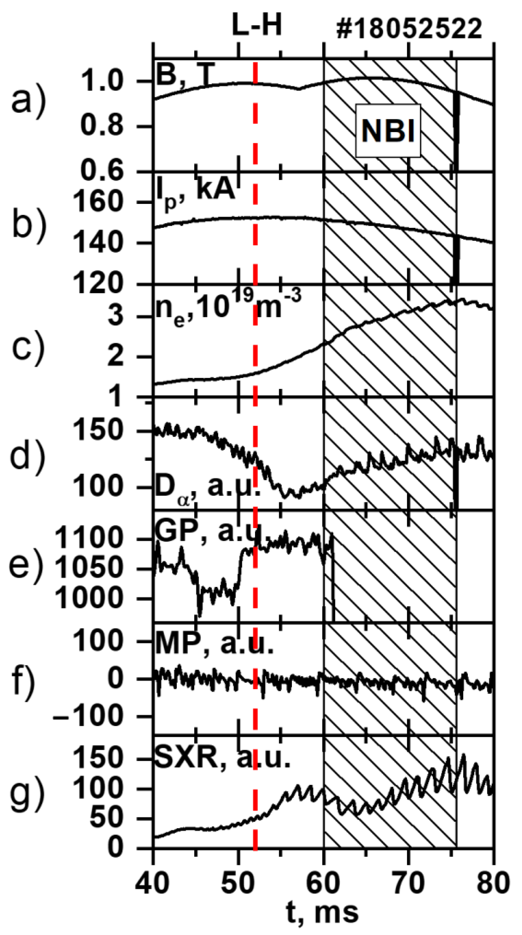
The typical, characteristic features of the TUMAN-3M H-mode (presented in
Figure 1, where the transition takes place at 52 ms and is marked by a dashed, red line), which are also observable in other devices and other types of H-mode, include:
- ○
an increase in plasma density suggesting the enhancement of the particle confinement time in H-mode by approximately a factor of 3 compared to a standard Ohmic heating (OH) regime (
Figure 1c);
- ○
- ○
rapid formation of the steep gradient zone at the periphery during the transition from OH to H-mode and the relatively slow rise of electron density in the bulk plasma;
- ○
pronounced changes in the electron temperature profile, testifying to thermal transport reduction in the gradient region as well as an increase in energy confinement time;
- ○
a slow increase in loop voltage during the last stage of H-mode, which is thought to be caused by impurity accumulation in the bulk plasma due to the improvement in particle confinement.
In the experiments regarding the influence of fast particles on plasma rotation, an additional heating method was employed after the transition to Ohmic H-mode had already taken place (see
Figure 2). Co-injection NBI (
) was used, which means that the beam was injected in the direction of the plasma current. It must be highlighted that the NBI did not play a role in the L–H transition, but rather the fast ion introduced into the plasma at a later point had an impact on plasma behavior and the change in parameters.
To demonstrate the effect of fast particles on plasma rotation, the discharges with “Ohmic H-mode” described above, both with and without NBI, are presented in this work. In an attempt to make the investigation accurate, the plasma parameters of discussed discharges were carefully compared, and only those with similar values relating to the magnetic field, plasma current and electron density were analyzed.
3. Doppler Backscattering
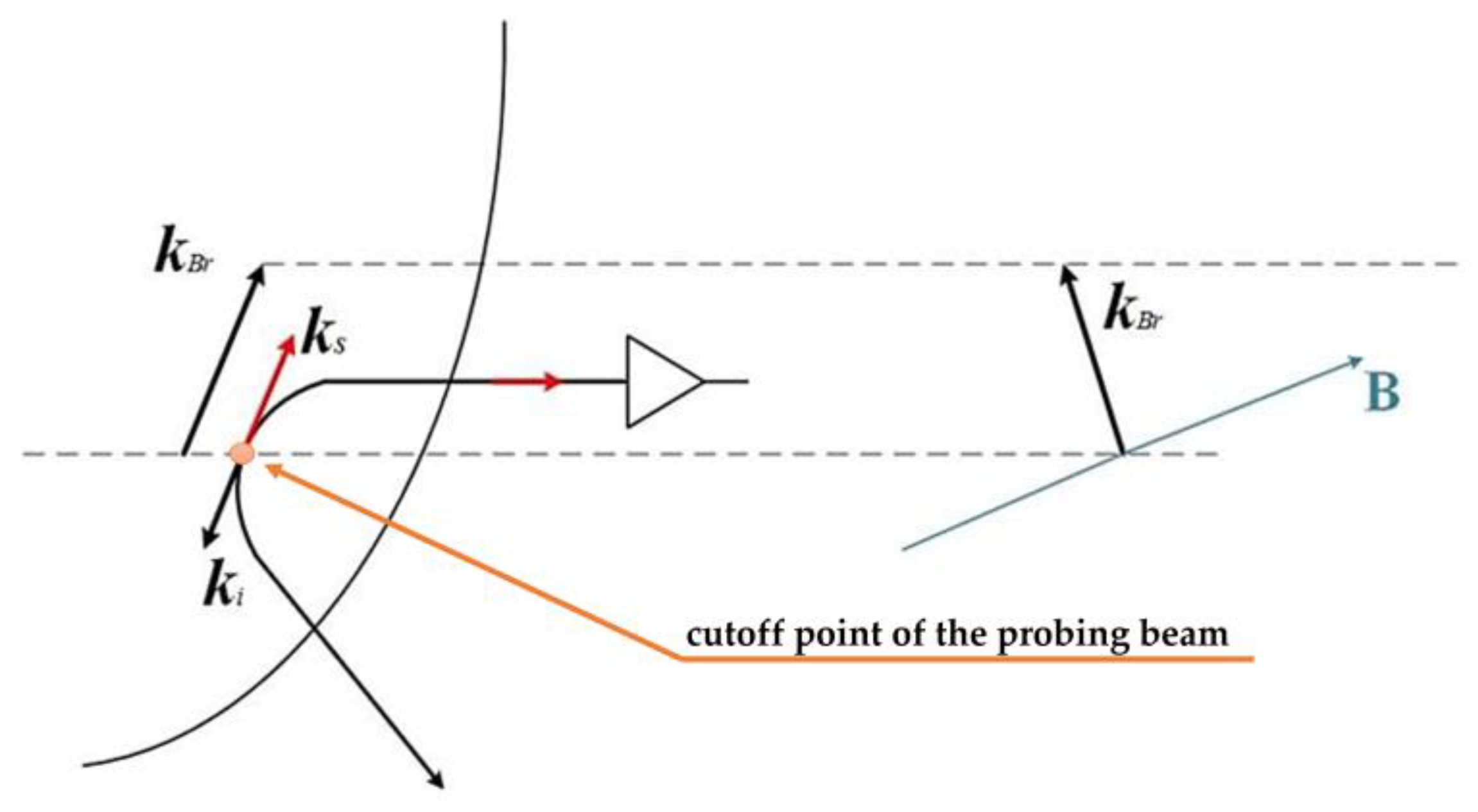
Doppler backscattering (DBS), also known as Doppler reflectometry, is a method based on recording the backscattered microwave radiation with an oblique incidence of the microwave beam. Scattering mainly occurs in the cut-off area of the microwave beam (the point where the beam changes its trajectory) in plasma fluctuations with selected wave vector
, which satisfies the Bragg condition for backscattering:
I, where
is the wave vector of the incident wave in the cut-off region (see schematic representation in
Figure 3). When the fluctuating plasma moves in the diamagnetic direction with a certain velocity, a Doppler frequency shift of backscattered radiation appears and can be described by the formula
, where
is the turbulence velocity in the measurement frame, and
is the turbulence wavenumber. In magnetically confined plasmas, the density fluctuations are aligned along the field lines, so, typically,
, making it possible to estimate the shift as
. So, the Doppler reflectometer is only sensitive to specific, perpendicular wave vector values.
The Doppler frequency shift
can be obtained from the DBS measurements as the position of the ‘center of gravity’ of the complex signal
spectral density or the derivative of the phase of the complex signal [
21]. For this purpose, the complex DBS signal spectrum is calculated so as to investigate the Doppler shift and, consequently, the rotation velocity. The sign and value of the shift allow the determination of the direction and value of the velocity
. The actual velocity extracted from the Doppler shift contains two components:
. Both terms provide valuable information about the plasma. A measurement of
and its direction say something about the type of turbulence present, while knowledge of
can give the values of the radial electric field.
Reflectometer Hardware
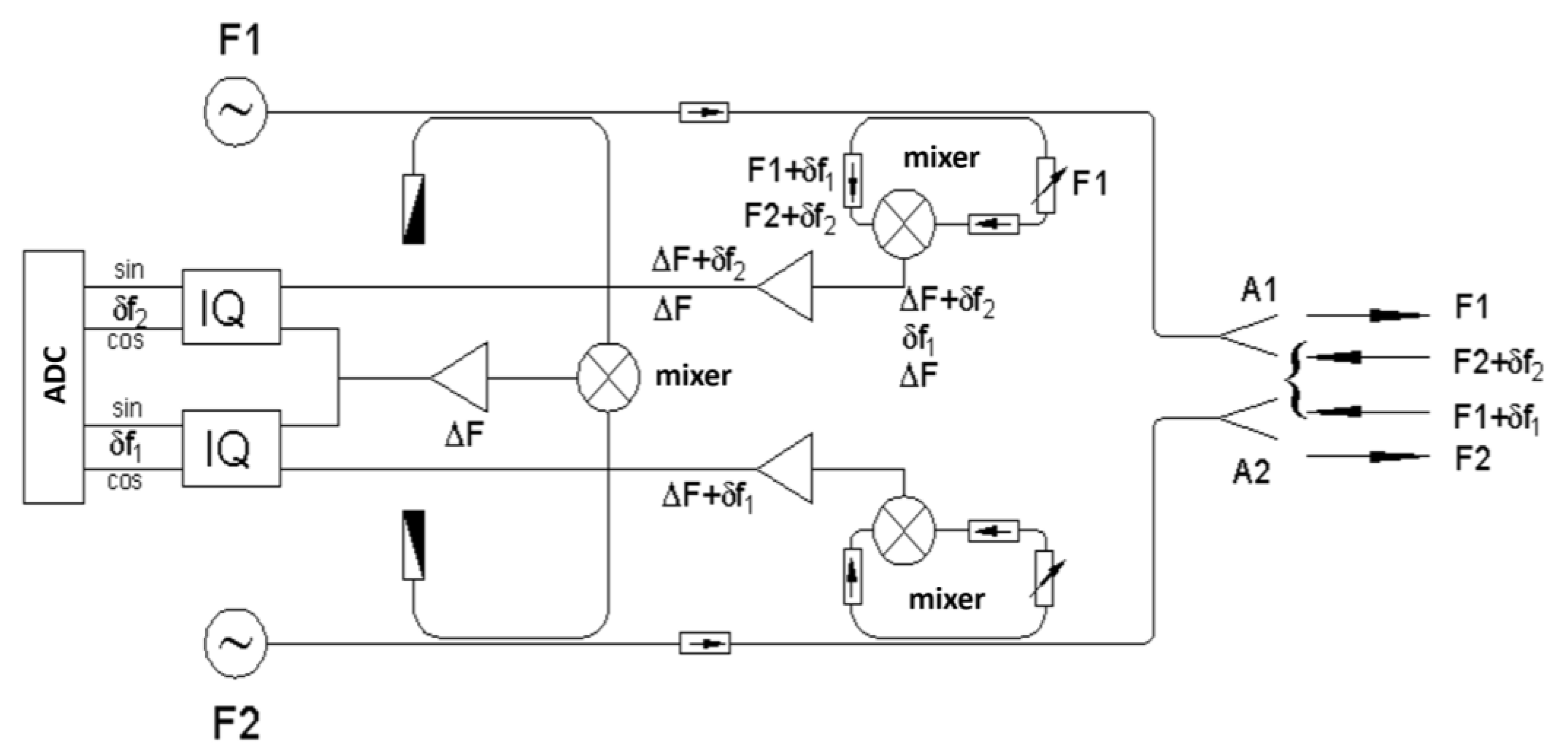
Figure 4 depicts a schematic of the two-frequency (referred to as two-channel) DBS system installed in TUMAN-3M. Its design is similar to the one used in the reflectometer in the JET tokamak described in work [
22]. It consists of two heterodyne schemes that are used for detection of the backscattering from the plasma. Each of them works on the principle of quadrature IQ detection. The main idea behind the system’s implementation is that the two generators are used for both probing the plasma with an incidence beam and for producing a reference signal at heterodyne reception, allowing for the Doppler shift to be extracted from the signals.
This system was previously used in TUMAN-3M to study a variety of phenomena. For instance, the geodesic acoustic mode (GAM) and its various qualities were thoroughly investigated using DBS [
23,
24], and the results of these measurements helped researchers to understand the physics of the transition to H-mode initiated by the developments of these modes [
25,
26,
27]. However, this is the first series of experiments where the characteristics of the plasma with NBI were studied using DBS in TUMAN-3M.
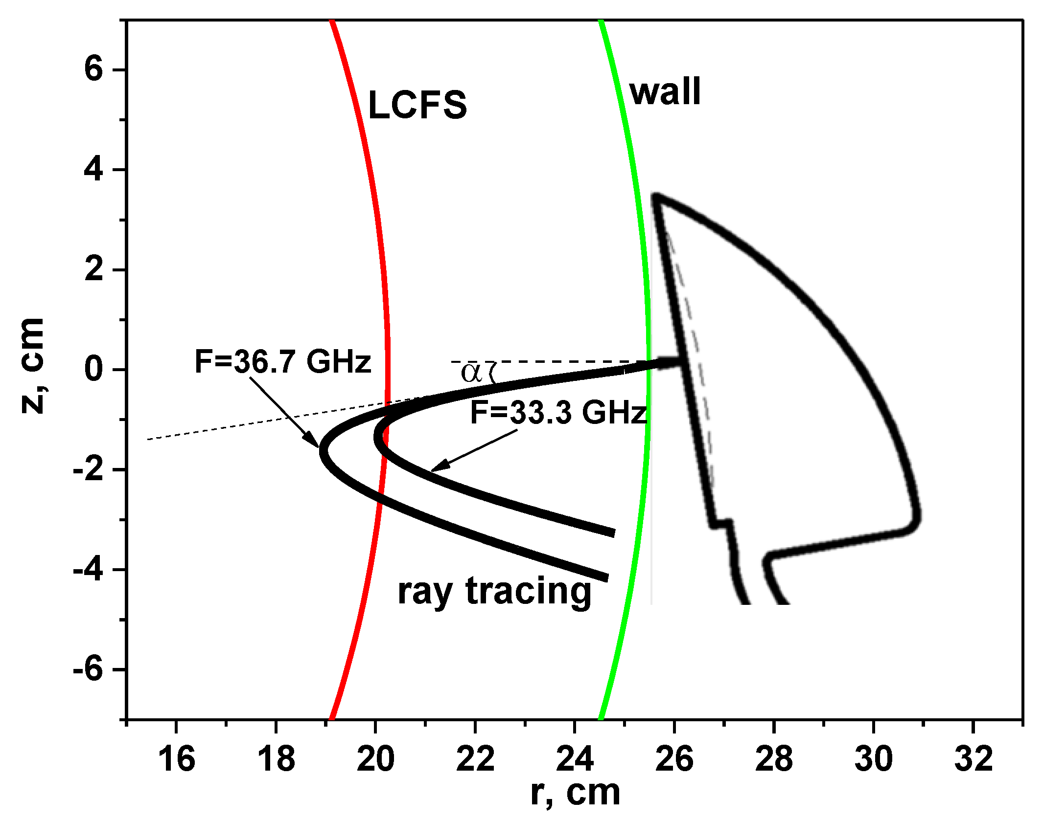
In the experiments described in this work, two different frequencies (always indicated in figures) were used for plasma probing, which allowed us to measure the plasma rotation velocity at different locations or at different radii. In order to follow the trajectories of the beams in the TUMAN-3M tokamak, a special code was developed which uses the density profiles obtained by an interferometer to perform the ray tracing. An example of the performed ray tracing is presented in
Figure 5. The black lines are the trajectory of the probing beams sent into the plasma at an angle, and at a given frequency, with a higher probing frequency cut-off being further into the plasma. The red line corresponds to the last closed flux surface (LCFS), or the separatrix, indicating the area in which the measurements took place. Additionally, the tokamak wall (green line) and position of the hog-horn DBS antenna are depicted in
Figure 5.
4. Experimental Results of Rotation Velocity Measurements
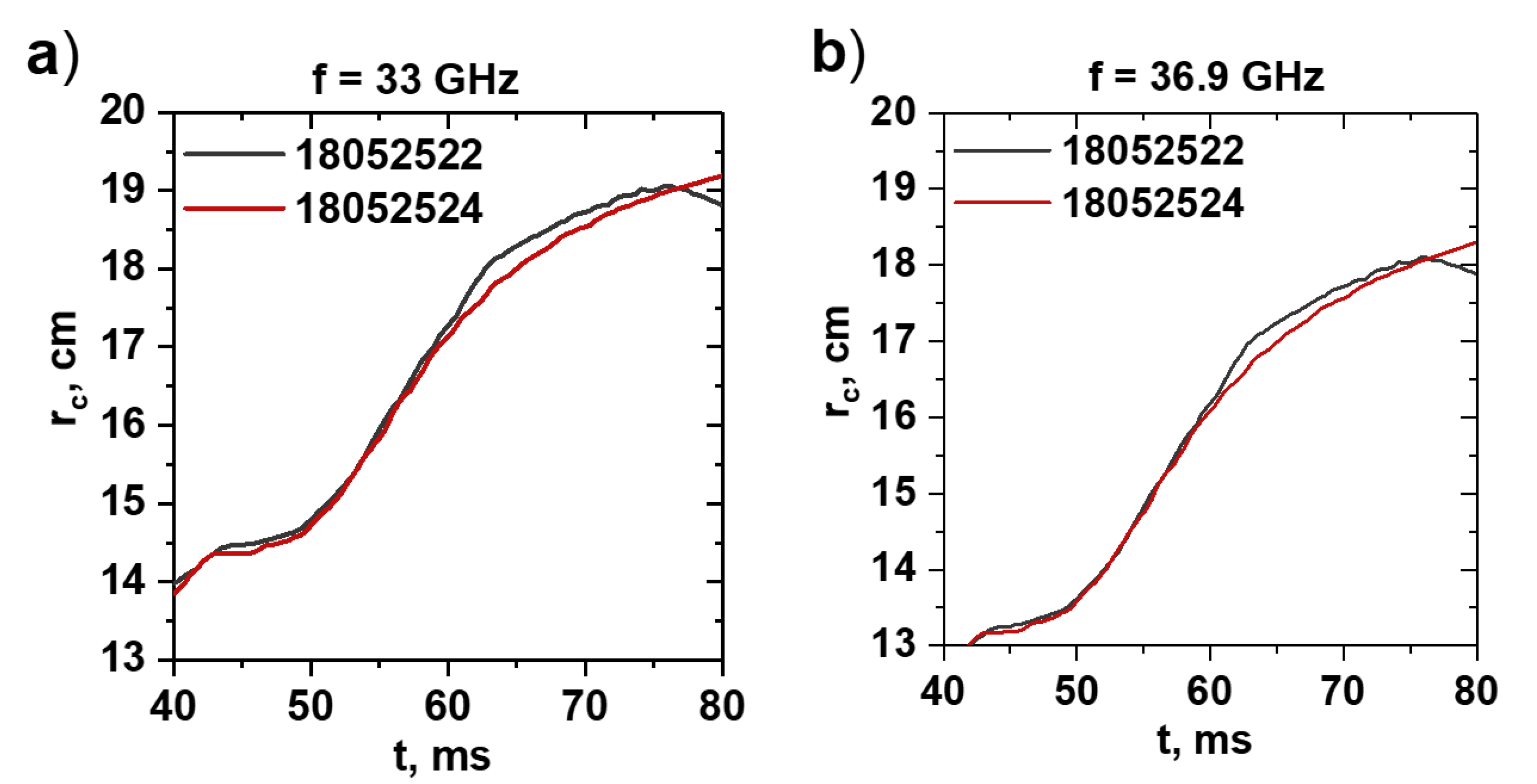
In order to determine the cut-off position of the probing beams in the TUMAN-3M tokamak, information about the discharges, such as the temporal evolution of plasma density, its radial profile, reflectometer incidence angle and probing frequency, was used. Information on the position of the cut-offs is necessary so as to know whether the localization of the measurements in the compared discharges (for instance, #18052522 and #18052524 in
Figure 6) coincides and, thus, justifies any further analysis.
For this purpose, the radius of the cut-off was calculated in time and was analyzed both before and after the NBI. The obtained temporal evolution is presented in
Figure 6. As one can see, the localization was very similar in both discharges presented and for both frequency channels, which implies that any changes noted in the profiles of the rotation velocity were not due to the analysis of different plasma areas, but rather signified a process being performed in the plasma.
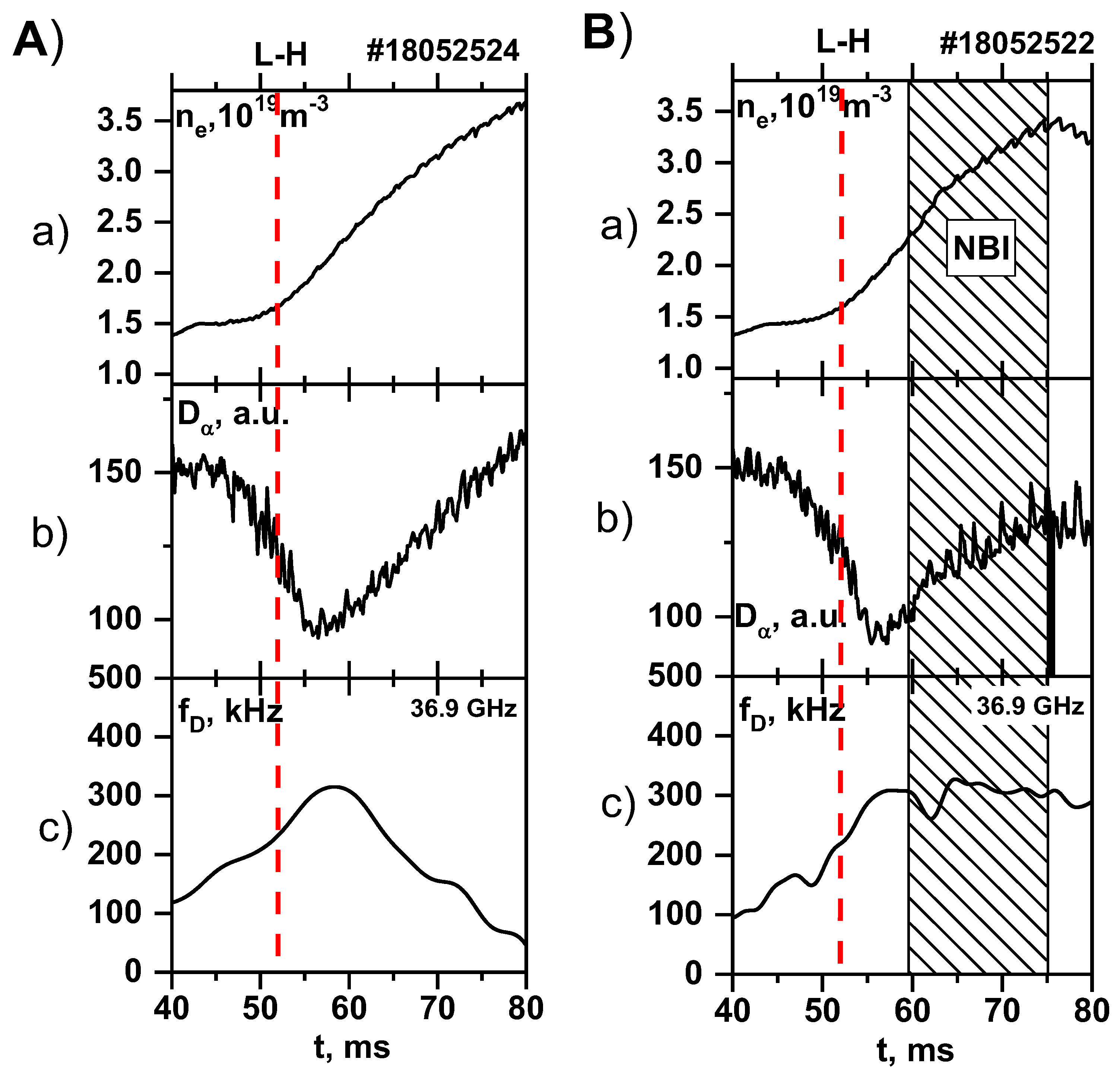
Further analysis of the DBS signals involved the calculation of the Doppler frequency shift so as to observe the temporal evolution of the plasma rotation velocity. The results of the shift for the 36.9 GHz probing frequency can be seen in
Figure 7, which also depicts the plasma parameters, such as electron density (
Figure 7a) and the
signal (
Figure 7b) before and after the L–H transition. These are shown so as to highlight the similar nature of the velocity in both discharges up until the moment when NBI was introduced into the plasma, as demonstrated in
Figure 7B(c).
Before the 60 ms mark (when the NBI was introduced into the tokamak plasma), the shift values were very similar. After the drop in
, and along with a steady increase of the electron density, the Doppler shift observably grew in time to the value of around 300 kHz after the transition to H-mode (it is worthy of note that the Doppler shift generally does not reach values above 200 kHz in the case of discharges with no H-mode). In the case of the entirely Ohmic H-mode, after reaching this peak, the shift gradually decreased until the end of the discharge. This can be explained by the movement of the cut-off radius towards the LCFS, where the velocity value becomes equal to zero. However, in
Figure 7B(c), while we can clearly still see a drop in the shift in the temporal evolution right after the NBI was turned, later on, after as a delay of several ms, it was followed by a return of the Doppler shift to its peak values, and it remained at roughly this value both during injection and even some time after the NBI was turned off.
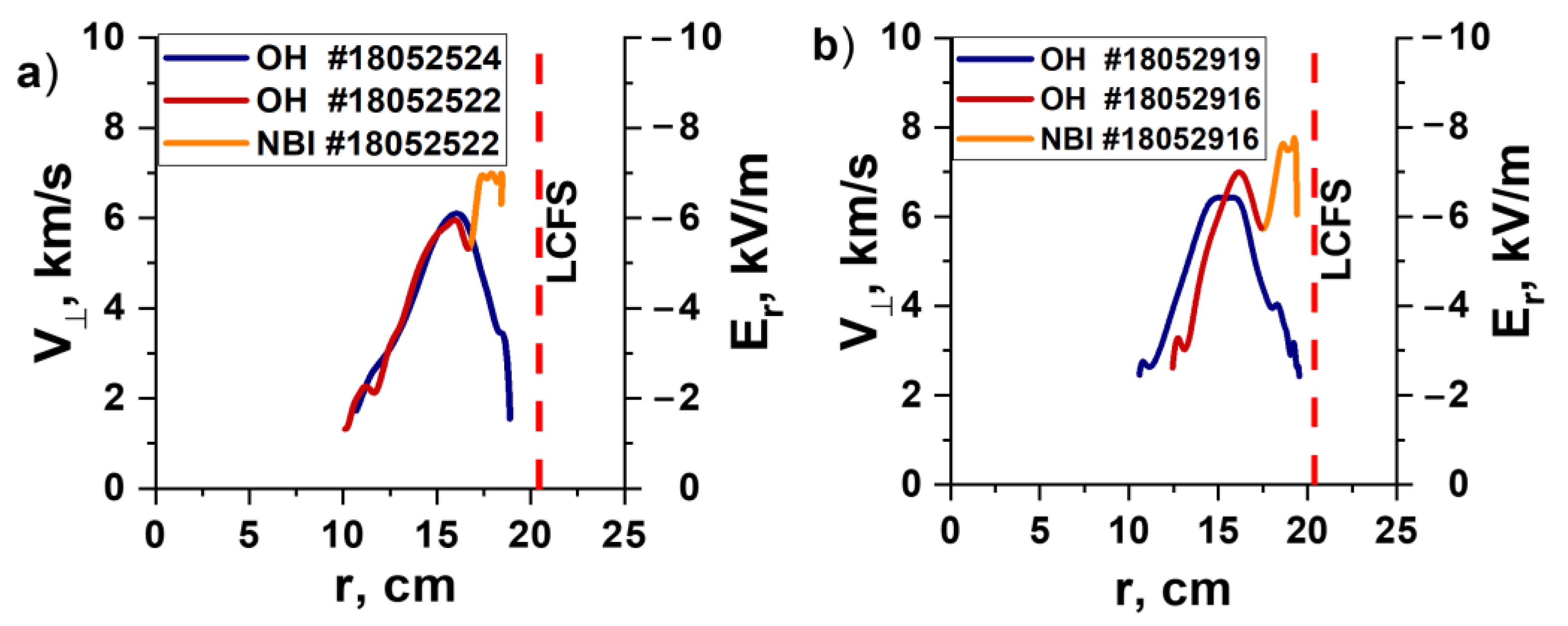
These changes were also demonstrated in the form of the calculated radial profile of the poloidal rotation velocity, as well as the radial electric field, shown in
Figure 8. In
Figure 8a, one may observe the radial velocity profiles for the discharges previously discussed in this section. They highlight the differences in the rotation at the periphery of the plasma (closer to the LCFS) associated with the NBI. At radii from 10 cm to 17 cm, the velocity values and behavior were very similar in their increase to a peak of around 6 km/s and, later, their decrease, with no significant contrast noticeable between the two profiles. This is highlighted by the fact that, during this time, both discharges were in the Ohmic heating stage (the colors in
Figure 8 represent different discharges and different heating methods). However, moving closer to the separatrix, the spike of the velocity due to NBI was in contrast to the slow decline in the Ohmic H-mode case. The orange line in
Figure 8a shows that, after the 17 cm radius, NBI grew up to values of 7 km/s and remained like that for several cm, after which the values dropped again. Additionally, the profiles for the pair of discharges presented in
Figure 8b are from the same series of experiments with similar plasma and NBI parameters; also, the same probing frequencies were used. In this case, some differences in the profile were observable even without NBI injection (this is because the pressure profiles were not the same, so the values of the velocity and radii varied). The overall behavior remained similar, and the reaction to NBI was of the same nature, with the exception of the values of the velocity being slightly higher. One can see from the orange profile in
Figure 8b, that it reached about 7.8 km/s at its highest point. This indicates that the difference in the rotation velocity still had more to do with the injected fast particles than simply the location of the measurements.
The radial electric field scale is also presented in
Figure 8. Its values were obtained using the ExB drift velocity formula, meaning that the magnetic field presented in
Figure 1a and
Figure 2a was used in these calculations. The resulting electric field had negative values, which is an important plasma characteristic.
5. Discussion about the Possible Effects on Plasma Rotation
When analyzing the obtained data, a variety of factors that could have influenced the differences in rotation velocity initially came to mind.
First and foremost, our analysis and calculations of the cut-off positions in the pairs of compared discharges clearly indicated that the disagreement in measurements was not associated with having data from different radii.
Additionally, one may assume that the poloidal rotation velocity of the plasma is affected by magnetohydrodynamic (MHD) behavior. A closer look at
Figure 1 and
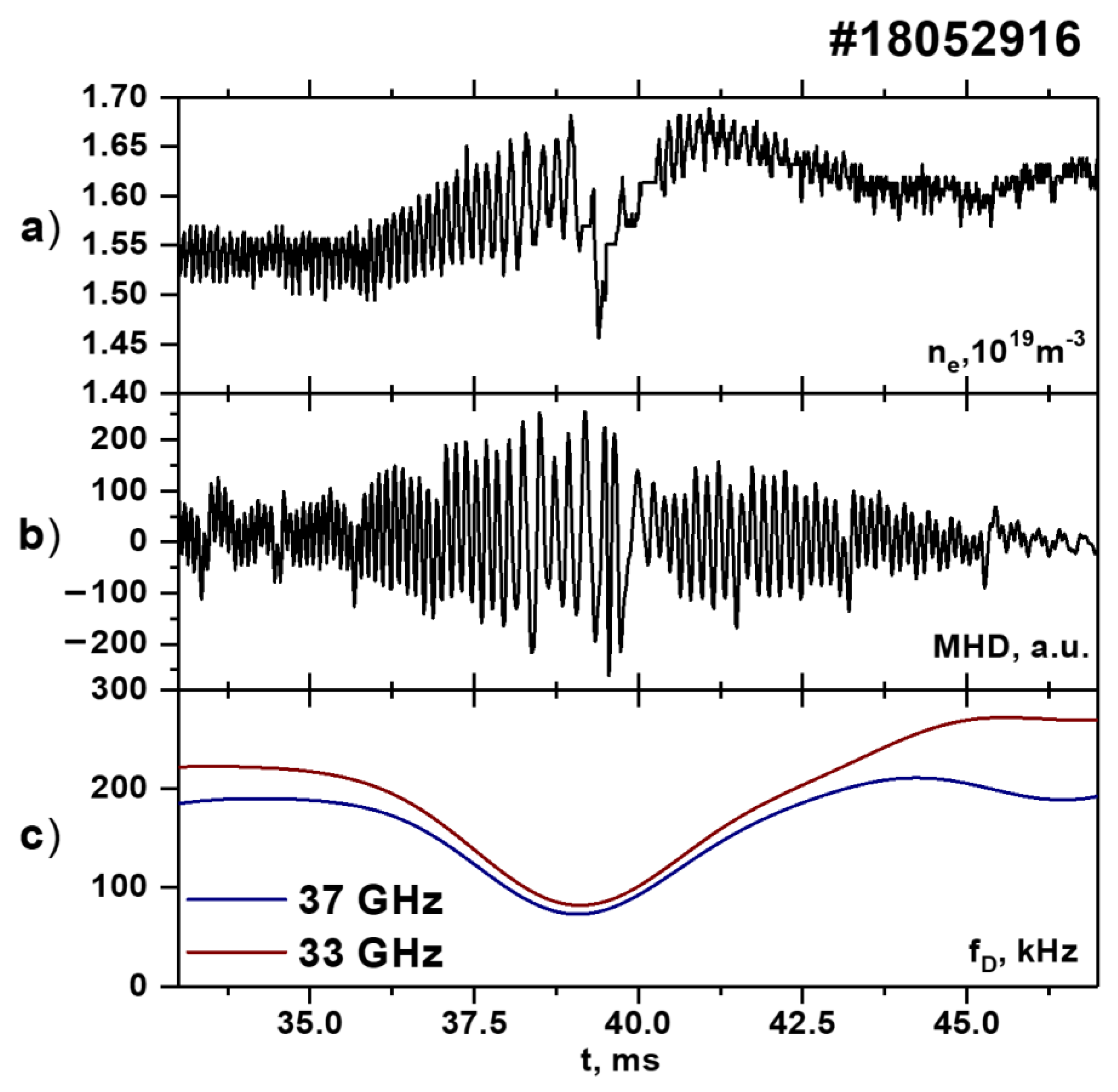
Figure 2 highlights that, in both cases (with and without NBI), the magnetic probe signals were quite similar and had the same characteristics. However, not all MHD activity may be apparent in the magnetic probe signal, such as standing MHD waves. To disprove this as being the key influence, we present the data in
Figure 9. In the signal of the magnetic probe (
Figure 9b), there was clear MHD activity in the form of magnetic islands, and this led to the reaction in the signal of the interferometer (
Figure 9a), which highlights that MHD can greatly change the plasma parameters. It is also evident that, as the MHD amplitude increased, there was an observable decrease in rotation velocity, which was demonstrated in the form of the measured Doppler frequency shift in
Figure 9c. What this also signifies is that the radial electric field also changed in the direction of more positive values, as it can be noted that the local minimum of the plasma velocity corresponded to the magnetic island’s minimum rotation velocity and maximum amplitude. After this, the island began to rotate faster again, which was accompanied by a decrease in the amplitude of the magnetic probe signal and an increase in its frequency; the rotation velocity of the plasma returned to the same values as before the development of the magnetic island. This phenomenon has been studied thoroughly in TUMAN-3M in previous experiments [
28,
29] and explained theoretically [
30]. It is important to note that magnetic islands generally adversely affect the development of plasma discharge and, in some cases, even lead to its disruption. The rotation velocity was described as one of the key parameters that affects confinement with regard to MHD activity in work [
31]. All these points lead to the assumption that, in these experiments, the MHD influence could not have led to the effects observed in the results and, thus, should not be considered.
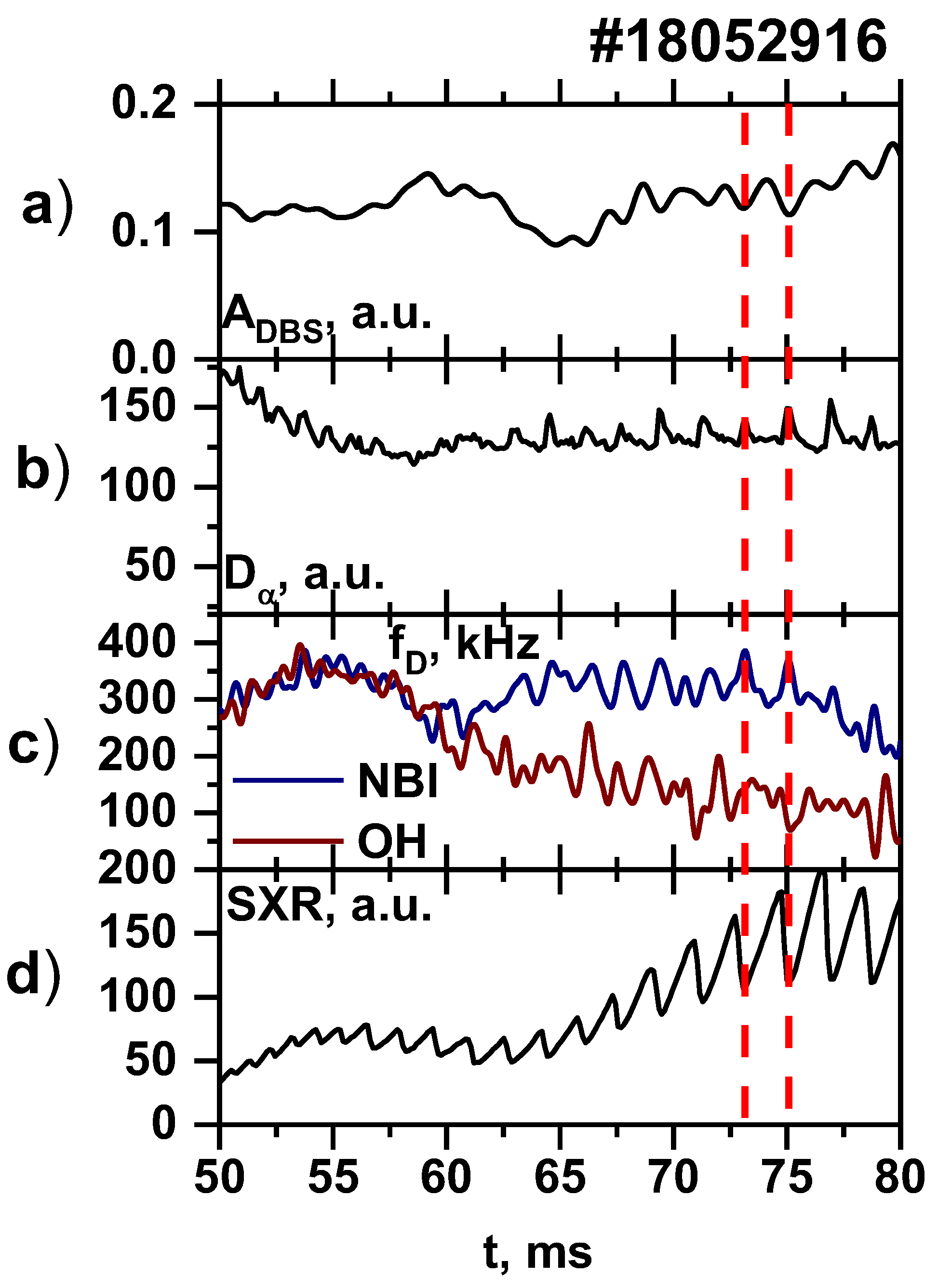
Apart from MHD activity, it is possible that edge-localized modes (ELMs) play a role in plasma rotation. While they are not very pronounced in the TUMAN-3M tokamak (see
Figure 10b), they were present in the form of small bursts in the
signal following a sawtooth crash, as shown in
Figure 10d. Such small ELMs have been observed in TUMAN-3M under various conditions, and their nature is not entirely understood; however, there is evidence to indicate that the mechanism behind formation of the ELMs in TUMAN-3M could be similar to the one described in paper [
32]. During these weak ELMs, the backscattered power decreases, as was showcased through the amplitude DBS signals shown in
Figure 10a. In addition, during each burst, the rotation velocity of the plasma increased a little (
Figure 10c), but it is possible that the ELMs deformed the electric field profile, similar to the suggested effect they had in work [
33]. However, the velocity fluctuations caused by the ELMs were insignificant when comparing measurements in Ohmic H-mode and during NBI. Consequently, the observed influence on the velocity profile cannot be explained solely by the development of ELMs. However, it should be noted that the NBI leads to the formation of ELMs by a complex mechanism; the injected fast particles warm the central areas of the plasma, which causes an increase in the amplitude of the sawtooth, which, in turn, leads to ELMs at the periphery. Furthermore, the effect of ELMs on the radial electric field is an immensely interesting topic of research.
An effort was additionally made to investigate the way that NBI affects the plasma parameters. It was of keen interest to understand how the injected fast particles influence different areas of the tokamak plasma, which is demonstrated in
Figure 11. The main idea demonstrated was that no significant increase in temperature could be seen after NBI on the peripheral soft X-ray (SXR) channels (
Figure 11c), which was not the case for measurements in the core (
Figure 11b). In addition, there was no significant increase in density after NBI in the peripheral interferometer channels. This is not surprising, because most of the fast particles of the beam are confined in the core region where the corresponding heating occurs. So, this means that, with the decreasing pressure and its gradient, one should not expect an increase in the electric field (the neoclassical one), which we observed.
There is the possibility that the phase velocity of the fluctuations changed due to the NBI. However, this assumption was again refuted by the fact that, at the periphery, fast particles were not generally confined and seemed to have little effect on the tokamak plasma or on density fluctuations or turbulence in particular, meaning that they could not be responsible for the dramatic changes in rotation velocity behavior.
However, there can be no doubt about the dependence of the rotation velocity behavior on the presence of the NBI and the injected fast particles. Due to co-NBI being specifically employed in these experiments in TUMAN-3M, two main mechanisms could have played a role in the formation of the radial electric field. The first one is the toroidal plasma rotation in the direction of the plasma current, and the second one happens as a result of the loss of the fast ions from the plasma. The former is accompanied by the formation of a positive electric field (generally has more of an effect on the core plasma), while the latter leads to a negative electric field profile (generally has more of an effect on the peripheral plasma) [
34]. As the measurements show, the electric field in these experiments had negative values (
Figure 8); this led to the conclusion that the rotation behavior was influenced by the fast particle losses. Moreover, the positions of the cut-off were located close to the LCFS, meaning that the measurements took place in the edge plasma. The large values of the Larmor radius of the fast ions in the periphery also suggest that the fast particle losses were significant in these experiments, and, in general, this could have contributed to changes in potential and electric field and, hence, to the profiles of the rotation velocity.
6. Conclusions
So, all the aforementioned results allow us to come to the following conclusions. The experiments in TUMAN-3M with an Ohmic H-mode achieved only by gas puffing were analyzed in great detail, which led to the discovery that the injection of fast particles with additional heating in the form of NBI can greatly affect the radial electric field, which, in turn, influences the plasma rotation. In this work, the measurements of the poloidal plasma rotation using the DBS diagnostic were presented for cases of Ohmic H-modes both with and without co-injection NBI. The results were obtained for different plasma regions so the radial profile of the velocity could be calculated. The temporal evolution of the Doppler frequency shifts, as well as the rotation velocity and radial electric field profiles, indicated that the plasma rotation was influenced by the presence of the fast particles introduced into the bulk plasma through NBI. What was observed was that, in the case of purely Ohmic H-mode, the velocity increased to a certain value after the L–H transition and continued to drop steadily after reaching that peak. If NBI was injected into the plasma, the velocity, after a delay of several ms, started to increase again to its peak values and remained at that level for some time even after the injection of fast particles was stopped, despite the shift of the cut-off position to larger radii due to increased density. The question of what exactly causes such rotation velocity behavior was addressed, and a variety of factors was analyzed. After a detailed examination of all the evidence presented, the conclusion reached is that the loss of the injected fast particles influences the radial electric field, which, in turn, causes the ExB drift which is responsible for the behavior of the rotation velocity.

