1. Introduction
Antennas for 5G can be divided into two categories, one that is required at the user end and a second that is needed at the base station. In both of these categories, Multiple Input Multiple Output (MIMO) antennas have been seen as potential candidates to fill the requirement [
1,
2]. MIMOs are actually the combination of many same types of antennas to produce a required beam pattern, which is not easy to get with a single antenna. This combination of many antennas increases the design complexity and cost of the system. The user end, due to its limited space, is a suitable place to be designed with a MIMO antenna. The base station, on the other hand, can be seen as a potential place where different types of antennas can be tested for a required 5G performance. The selection of an antenna at the base station mainly depends on the range of its acquired parameters that are needed for 5G communication [
3]. Apart from a selected operating frequency range, a gain of more than 20 dB and a bandwidth of more than 1 GHz are required for a 5G antenna that is supposed to be used as a transmitter at the base station [
4,
5]. The additional and optional features of a 5G antenna also include polarization diversity and adaptive beamsteering [
6]. Polarization diversity could be handy to overcome the flaw of narrow bandwidth, while swift electronic beamsteering can reduce the number of antennas on the base station. The antenna operating frequency for 5G operation is mainly considered in the range of either millimeter wave or sub-millimeter wave [
7]. The common millimeter wave frequency ranges that are used for 5G-based research are mostly above 22 GHz. Array antennas, due to their ability of acquiring high-gain, have been widely proposed by the researchers to be used in the millimeter wave frequency range for 5G communication [
8]. Phased arrays and reflectarrays both can be good candidates for a 5G base station antenna. Between them, reflectarray does not require a phase shifter circuit, which significantly reduces its cost and design complexity as compared to a phased array antenna.
A microstrip reflectarray is generally considered as a planar phased array with performance features of the parabolic reflector [
9]. It was introduced to overcome the flaws of the curvy design of the parabolic reflector and the high complexity of the phased array [
10]. The collimation of incident signals from the surface of the reflectarray is performed by properly designing its unit cell element. Most of the recent works proposing 5G reflectarrays have worked on the enhancement of its bandwidth performance. However, in reality, acquiring a bandwidth performance of more than 1 GHz at millimeter wave range with reflectarray antenna is not a big issue. Its gain can also be increased by using a large aperture size. The main issue with a reflectarray antenna that limits its progression for 5G communication is its design complexity. The enhanced performance of a reflectarray antenna and its design complexity are complementary to one another. A simple design would also reduce its cost and make it suitable to be produced in large quantities.
Reflectarray performance can be enhanced by considering the modification in the design of its unit cell element [
3]. A unit cell is comprised of a conducting patch element printed on a grounded dielectric substrate. The substrate and patch both can be considered for possible design adjustments for performance improvement [
11]. A wide reflection phase (S
11 phase) range of unit cell element ensures a good bandwidth performance. The substrate of the unit cells can be used as stacked layers, or an air gap can be inserted in it before the ground plane to cope with the narrow bandwidth issue [
12,
13,
14]. However, this could increase the design efforts and make it difficult to be fabricated, especially at millimeter wave frequencies. On the other hand, different patch element designs, such as a combination of elements [
15], fractal elements [
16], and multiple phase tuning stubs [
17] can also be used for the performance enhancement. Among them, the last two designs are only suitable for low frequency operation due to their design complexity, and the first one can face mutual coupling issues due to more than one element being used in it [
3].
The primary purpose of this research work is to produce a reflectarray unit cell element with dual resonance response without using a dual patch or dual layer structure. This dual resonance response is further utilized for an extended reflection phase range to acquire a wider bandwidth performance. Dual resonance response with a single layer can also be acquired with a Fractal type element. However, Fractal elements have a very complicated design structure; that is why it is challenging to implement them at very short wavelengths of high frequencies [
3]. Additionally, it is normal to use an air gap in the substrate of a reflectarray antenna for bandwidth improvement, which increases the design efforts. The addition of this air gap with a minor fabrication error can cause a huge deflection in the resonance of the reflectarray antenna at high frequencies. Therefore, this type of air gap is not used in this design of asymmetric patch reflectarray antenna, which relies totally on a new shape of the patch element to generated dual resonance response.
A similar work published in [
4] also proposes a reflectarray antenna for 5G communications. The work reported in [
4] contains reflectarray of conventional circular ring elements with full ground, whereas this work offers a novel asymmetric patch reflectarray element with ground ring slots for bandwidth and gain enhancement for 5G application. Moreover, this work also offers an improved reflectarray operation especially in terms of a smaller size, wider reflection phase range and additional polarization as compared to the work published in [
4]. The detailed comparison between this work and [
4] has been presented alongside with many other related works in
Section 5 of this paper.
The design complexity is always a major factor if a reflectarray antenna is proposed for 5G operation. Therefore, a simple design of the unit cell patch element is required with a wide reflection phase range and suitable aperture size for reflectarray compatibility with 5G communication. In this work, a single layer asymmetric patch unit cell element is first time introduced to enhance the reflectarray performance at 26 GHz frequency. The main novelty of the proposed work is the introduction of a new asymmetric patch reflectarray element that can produce two close resonances for reflection phase range enhancement without using an extra resonant layer or resonant element. A simple design of the proposed asymmetric patch element that can be easily fabricated at short wavelengths of high frequencies is also considered as a huge advantage. The asymmetry in the design of the patch element is used as a tactic to enhance its reflection phase range. Asymmetry also creates a high level of unwanted cross polarization [
18], which is tackled by selecting a proper element orientation on the reflectarray surface. Simulations of unit cell element and full reflectarray are performed by CST Microwave Studio within a frequency range of 24 to 28 GHz. The selected frequency range is considered due to its application in 5G communications [
4,
19]. The proposed design of the reflectarray antenna has also been experimentally verified. In the end, the proposed reflectarray antenna with its acquired parameters has been used as an indoor base station to measure its signal strength at various locations for 5G communication.
2. Asymmetric Patch Unit Cell Element
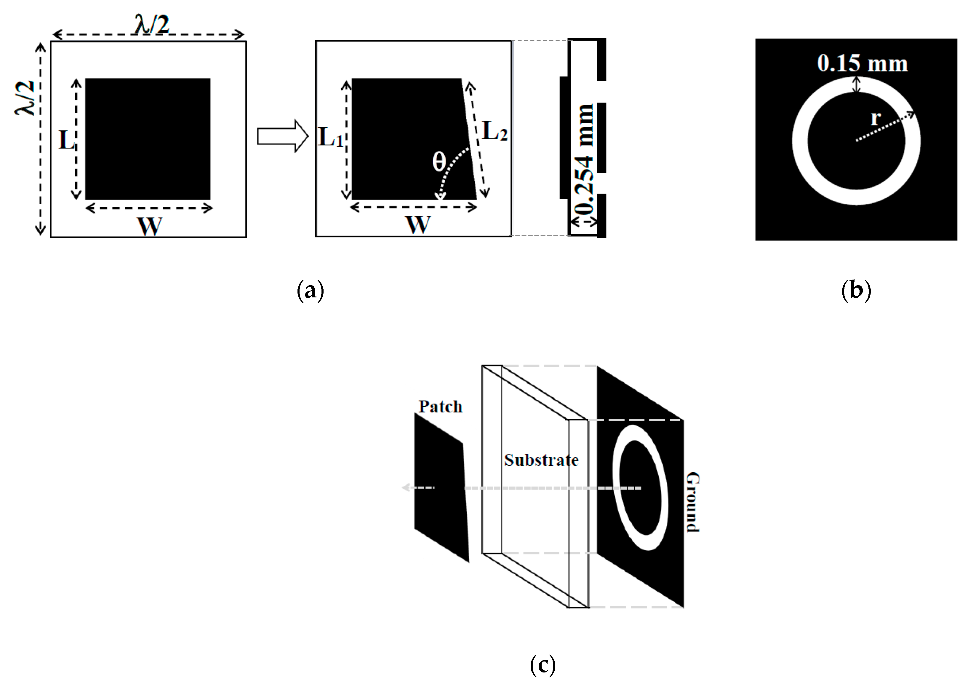
The asymmetric patch element has been developed from a square patch element that is taken as the primary structure to construct it. A low loss Rogers Rt/D 5880 material with a dielectric constant of 2.2 and a thickness of 0.254 mm is selected to hold the grounded asymmetric patch element. The substrate length and width have been set to be λ/2, which is 5.77 mm at 26 GHz resonant frequency. The evolution of an asymmetric patch element from a standard square patch is demonstrated in
Figure 1a. It can be seen from
Figure 1a that a vertical side of the square patch element is tilted to some optimized inclination angle (
θ). Due to the tilting of a side of the patch element, two different lengths (
L1 and
L2) have been introduced in the same patch element. The resonance of a microstrip patch elements depends on the dimension of its length. Therefore, in the case of an asymmetric patch element, two different resonances can be generated from a single element as given in the following equation [
20].
Here, c is the speed of light, εeff is the effective dielectric constant of the substrate, while f1 and f2 are the two resonant frequencies associated with the two different lengths L1 and L2 of the asymmetric patch element.
A standard procedure for the simulation of a reflectarray unit cell element is adopted that is based on the large array approach, as explained in [
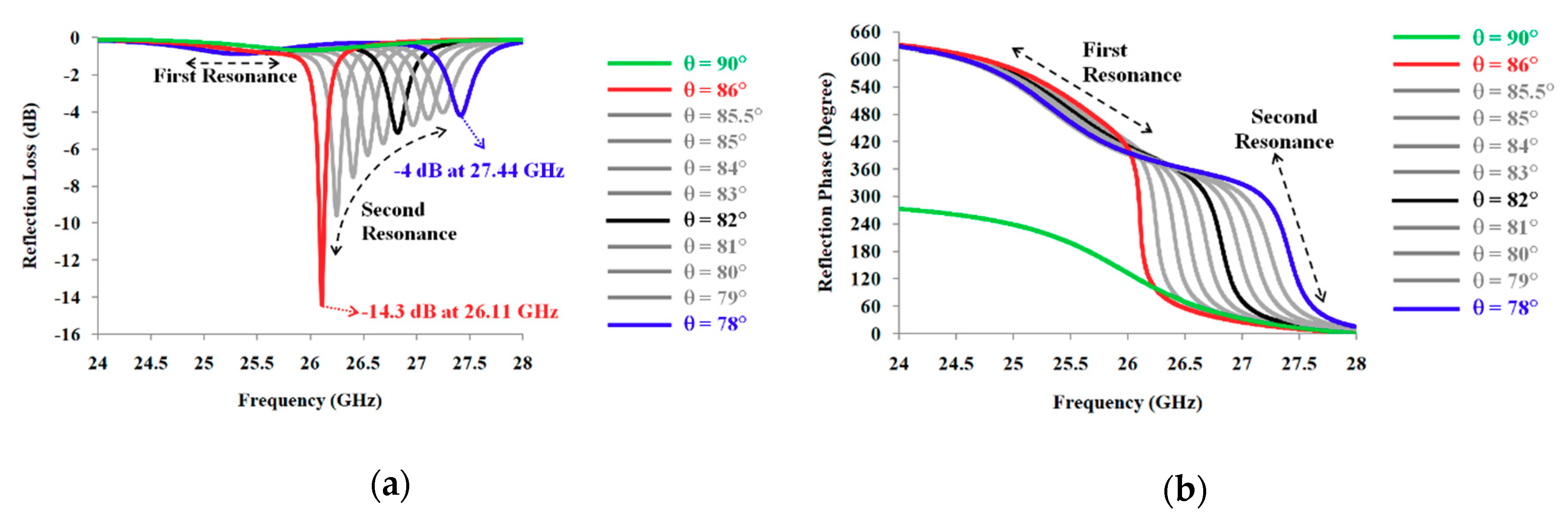
21]. In the simulation method, the reflectarray unit cell is enclosed by the periodic boundary conditions to generate a large array approach. The periodic boundaries are comprised of pure magnetic and pure electric walls on right-left and top-bottom sides of the unit cell element respectively. A waveguide port is placed in front of the unit cell element at a distance of quarter wavelength to observe the reflective characteristics of the unit cell element. The boundary at the ground plane of the element is kept open as it backs the free space behind the reflectarray unit cell element. The dual resonance phenomenon of the asymmetric patch element can be seen from
Figure 2a, where simulated reflection loss (S
11 magnitude) of the asymmetric patch element has been plotted with respect to the inclination angle (
θ). It can be observed that when the inclination angle is decreased beyond 86°, an extra second resonance has been formed in the frequency response of the asymmetric patch element. The two resonances shown in
Figure 2 are occurred due to the asymmetric design of the unit cell patch element. At this optimization stage the center frequency of the first resonance is 25.5 GHz. Both the resonances offer their respective reflection phases of more than 300° and a collective reflection phase span of more than 600°. The asymmetric patch element without an inclination angle (
θ = 0°) would be a square patch element with an ordinary frequency response of a single resonance.
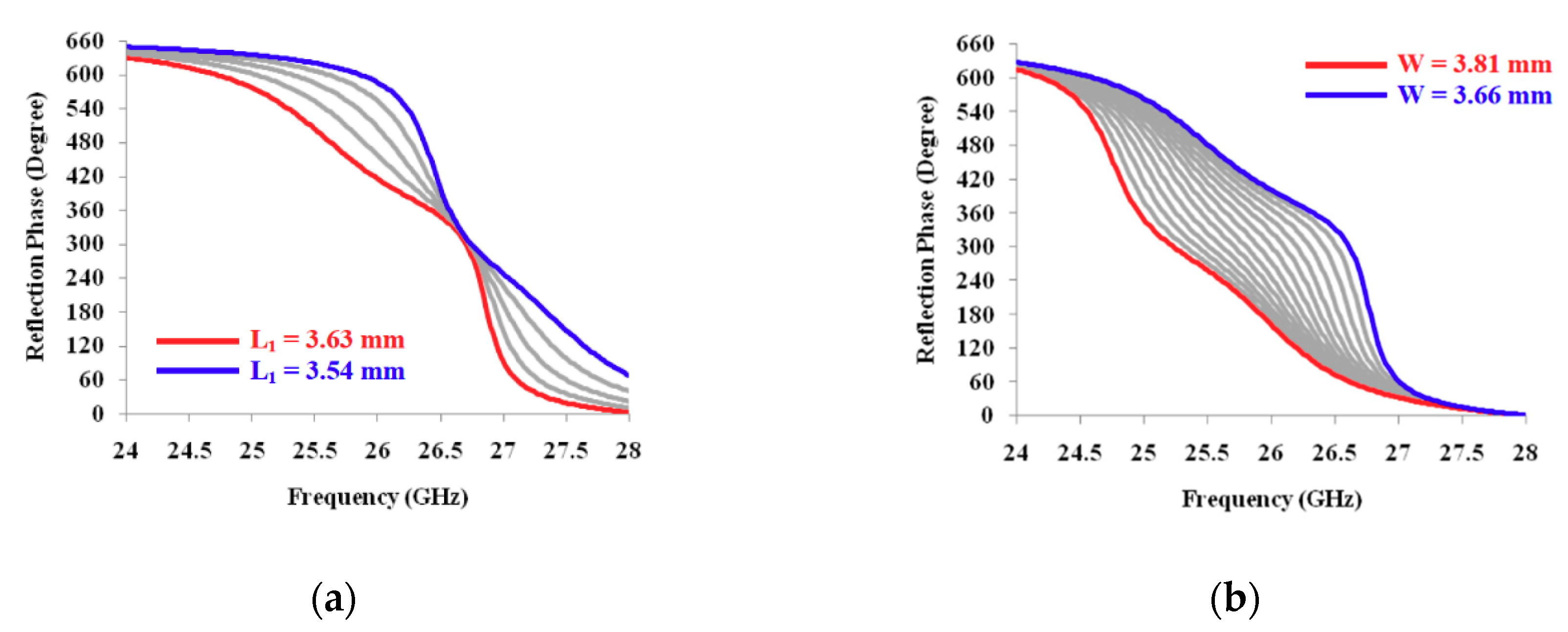
The dual resonance response, as driven in
Figure 2, still lacks the linearity in the reflection phase that is an important factor in getting an enhanced bandwidth performance. In order to get this linearity in the reflection phase, optimization has been performed with the variable length (L =
L1) and variable width (W) of the asymmetric patch element. The simulated results of this optimization have been shown in
Figure 3. It can be analyzed from
Figure 3a,b that the slope of the reflection phase is a function of change in length and width of the asymmetric patch element, respectively. Additionally, a linear reflection phase curve can be obtained with the asymmetric patch element if its dimensions are selected properly. These dimensions can be varied a little further to achieve the same resonant frequency when a ring slot is embedded in the ground plane. The optimized parameters of the asymmetric patch element at 26 GHz with the full ground and with circular ring slot in the ground are summarized in
Table 1. Values in the second column of
Table 1 belong to the optimization performed in
Figure 3, and values in the third column of
Table 1 are obtained by varying values of the second column when a ring slot is added in the ground plane.
The progressive phase distribution in the reflectarray can normally be acquired with the variable size of its patch elements or by applying the element rotation technique [
22,
23]. However, it would be difficult to change the overall size of the asymmetric patch element or rotate it while keeping its shape intact. Therefore, a circular ring slot, as depicted in
Figure 1b, has been embedded in the ground plane of the asymmetric patch element. The variable radius (r) of this grounded embedded ring slot has been used to progressively vary the reflection phase response of the asymmetric patch element [
24]. Additionally, the ground ring slot can easily support the dual linear polarization response of the symmetric patch reflectarray that is an essential parameter for 5G communications. The same dual linear polarization could also have been obtained by a square ring slot, but the square ring slot attains a larger defecting area than a circular ring slot. A larger defecting area in ground plane would result in an increase in the reflection loss performance, which is not good for a high-gain reflectarray operation. The width of this ground ring slot should be kept as minimum as possible in order to suppress the generation of the back radiations [
24,
25]. As depicted in
Figure 1b, the width of the ring slot is kept constant at 0.15 mm, because it is the minimum possible dimension that can be fabricated using available laboratory resources.
Figure 1c shows the alignment of the asymmetric patch element with the ground ring slot. It can be seen from
Figure 1c that the patch is situated in the center of the substrate that aligns directly with the center of the ring slot. All the control parameters that affect the results of asymmetric patch element have been mentioned in
Figure 1,
Figure 2 and
Figure 3 and
Table 1. The remaining parameters have been kept constant throughout the simulation process as they are not used to perform any change in the response of the asymmetric patch element. Those constant parameters include boundary conditions, waveguide port distance, substrate properties and substrate dimensions.
2.1. Asymmetry and Cross Polarization
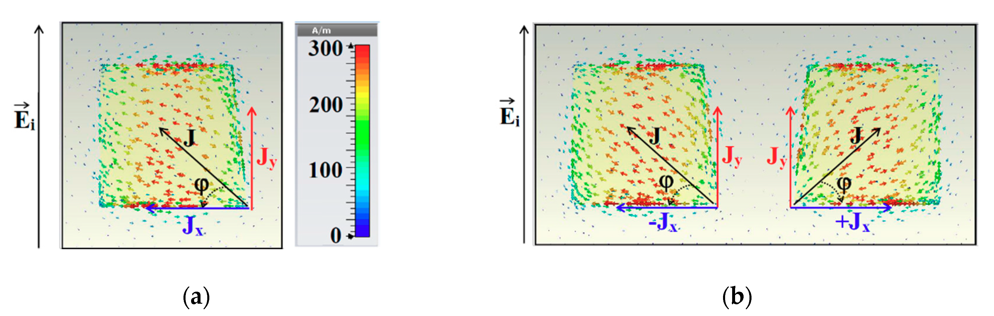
The asymmetric patch element has an inclined side instead of a vertical one. In this scenario, a vertically polarized incident electric field (
Ei) generates a diagonally flowing surface current (
J), as shown in
Figure 4a. The diagonal movement of surface current breaks it up into a vertical (
Jy) and a horizontal (
Jx) component. These surface current components induce a reflected electric field (
Ery and
Erx) in the same manner. The reflected electric field component
is called as co-polarized reflected electric field because it is in the same polarization with the incident electric field. Alternatively,
Erx is called as cross-polarized reflected electric field because it is in the orthogonal polarization with the incident electric field.
The effect of high cross polarization can be eliminated by mirroring the orientation of the elements on the reflectarray surface [
26]. The depiction of two mirror elements, which are horizontally flipped, is shown in
Figure 4b. As illustrated in
Figure 4b, the two horizontal components of surface current (+
Jx and −
Jx) are in the opposite direction to one another. The positive and negative signs of
are assigned to represent their opposite directions. In this scenario, the reflected electric field for two asymmetric patch elements can be calculated as described in the following derivation.
Equation (2) shows that the cross-polarized component of the reflected electric field can be eliminated if the asymmetric patch elements are arranged in mirror orientation to each other on the surface of reflectarray.
2.2. Experimental Results of Asymmetric Patch Element
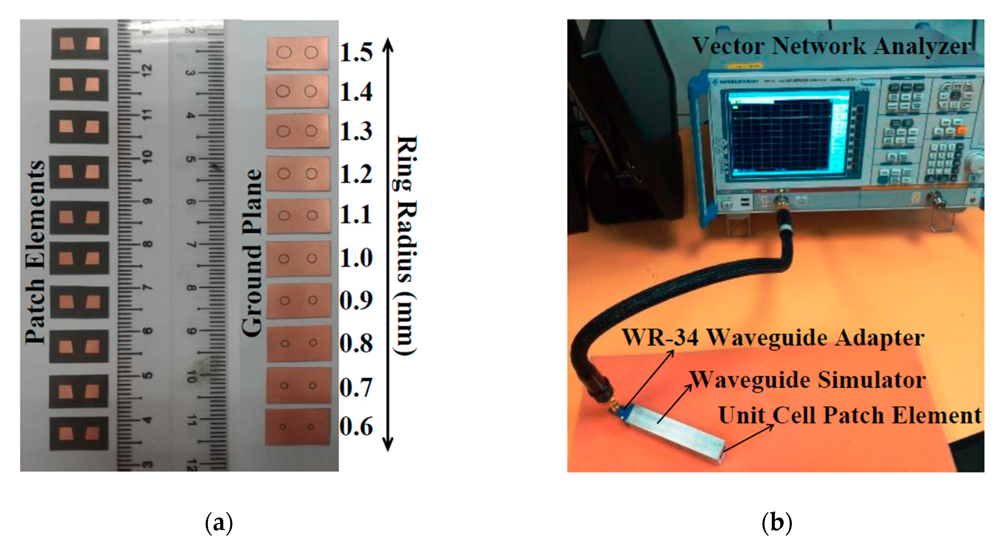
The experimental verification of the asymmetric patch unit cell element with embedded ground ring slots has been performed using scattering parameter measurements. The fabricated unit cell elements that have been used for the experimental purpose are shown in
Figure 5a. There are total of 10 different fabricated samples of the unit cells that have been used for the measurements. Change in the ground ring radius for the fabricated unit cells can be spotted from
Figure 5a, while all the asymmetric patch elements have the same size. The unit cell element contains two asymmetric patches, which makes it suitable to be aligned with the open end of the waveguide simulator. The waveguide simulator is a piece of the standard equipment used for the scattering parameter measurements of a reflectarray unit cell element [
27]. The rectangular dimensions of the waveguide simulator are obtained by considering it for the wave propagation of TE
10 mode. The unit cell element cannot be displaced or moved during the measurement as it is fixed within the open face cavity of the waveguide. Therefore, no deflection in the measured results is supposed to happen due to the mounting or placement of the unit cell element. The unit cell measurement setup is depicted in
Figure 5b, where the waveguide simulator is connected with a Vector Network Analyzer (VNA) through a standard WR-34 coaxial to waveguide adapter. A standard process of the VNA calibration using open, short and load connectors has been performed to properly calibrate the measurement system. The predefined dimensions of the waveguide simulator and WR-34 adapter make them suitable to be used from 22 to 33 GHz frequencies. Although, the scattering parameter measurements have been performed from 24 to 28 GHz.
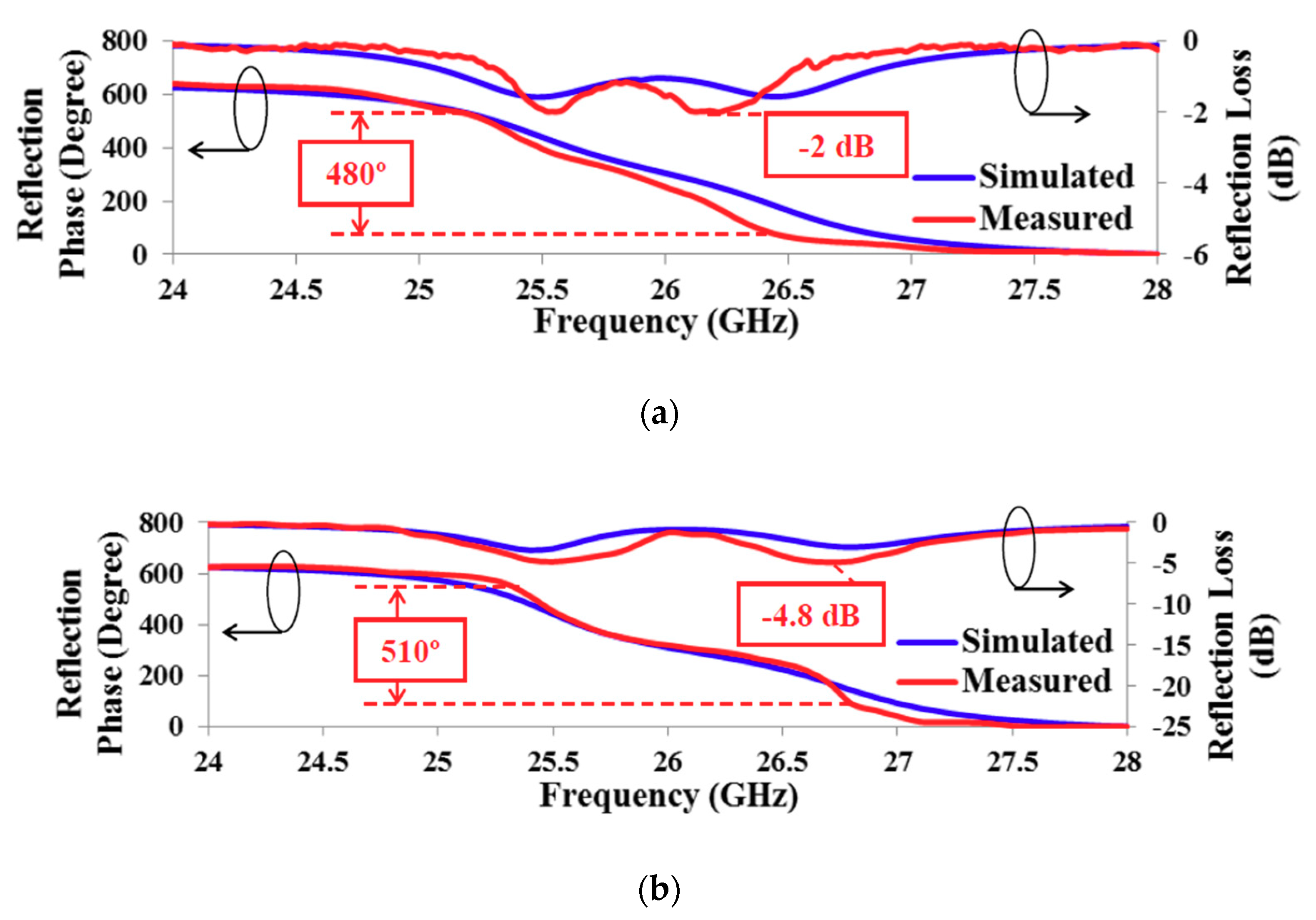
Figure 6a,b show the graphs of the reflection response of the asymmetric patch element with the full ground and with ground ring slot, respectively. A dual resonance response can be spotted in both the mentioned cases. Asymmetric patch with full ground is observed to offer measured resonances at 25.5 GHz and 26.25 GHz, whereas its counterpart with embedded ground ring slot attains measured resonances at 25.5 GHz and 26.75 GHz. The asymmetric patch element with and without ground ring slot has the dimensions that have been mentioned in
Table 1. However, as expected, a higher reflection loss performance has been observed from the asymmetric patch element with the ground ring slot as compared to a full ground element. The leakage currents in the ground ring slot are the main reason behind this higher reflection loss. Additionally, a higher measured loss as compared to a simulated one and a small deflection in the measured resonant frequencies are observed that occurs because of the unavoidable effects of the fabrication errors, waveguide, connectors and cables used during the measurements process. The full ground and slotted ground asymmetric patch elements attain a measured linear reflection phase range of 480° and 510°, respectively. This wide reflection phase range is essential for wideband performance in reflectarray antenna.
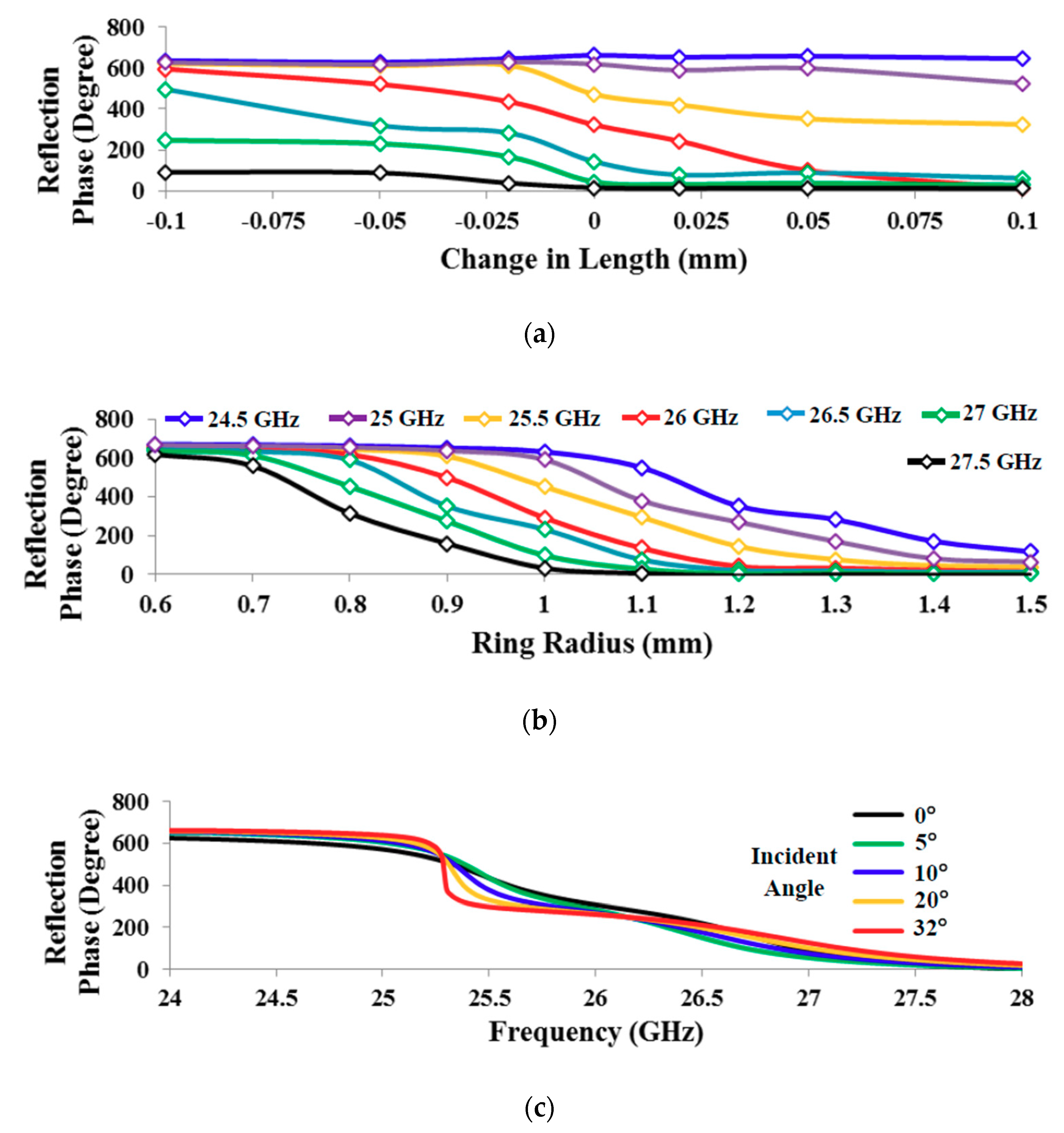
The progressive phase distribution of the asymmetric patch element at 26 GHz with the full ground and with the slotted ground is depicted in
Figure 7a,b, respectively. It can be analyzed that, the asymmetric patch element with the full ground does not acquire a wideband performance for the frequencies other than 26 GHz. It is because of the sensitive nature of the asymmetric patch element, as a full phase span requires just a change of 0.2 mm in length (
L1), which is practically hard to differentiate. Alternatively, a ground ring slot serves the same purpose with a change in radius of 0.9 mm, which is less sensitive than its counterpart.
Figure 7c shows the reflection phase response of the asymmetric patch element with the ground ring slot for different incident angles. A full phase swing can be observed up to 32° of incident angle, which is the maximum value in the proposed design of the reflectarray antenna of this work.
3. Reflectarray of Asymmetric Patch Elements
A standard procedure of designing the microstrip reflectarray antenna with its proper experimental validation is explained in [
10,
22,
28,
29]. The same process has been followed to design and validate the asymmetric patch reflectarray antenna with a variable radius of its ground ring slots. The elements of a reflectarray are needed to be properly designed with an accurate progressive phase distribution to get proper collimation of its reflected signals. The progressive phase distribution on the surface of a reflectarray antenna is calculated using Equation (3) [
10].
where Δ
φ is the change in reflection phase,
φ is the progressive phase center,
φi is the reflection phase of a selected element,
f is the focal length of the feed and
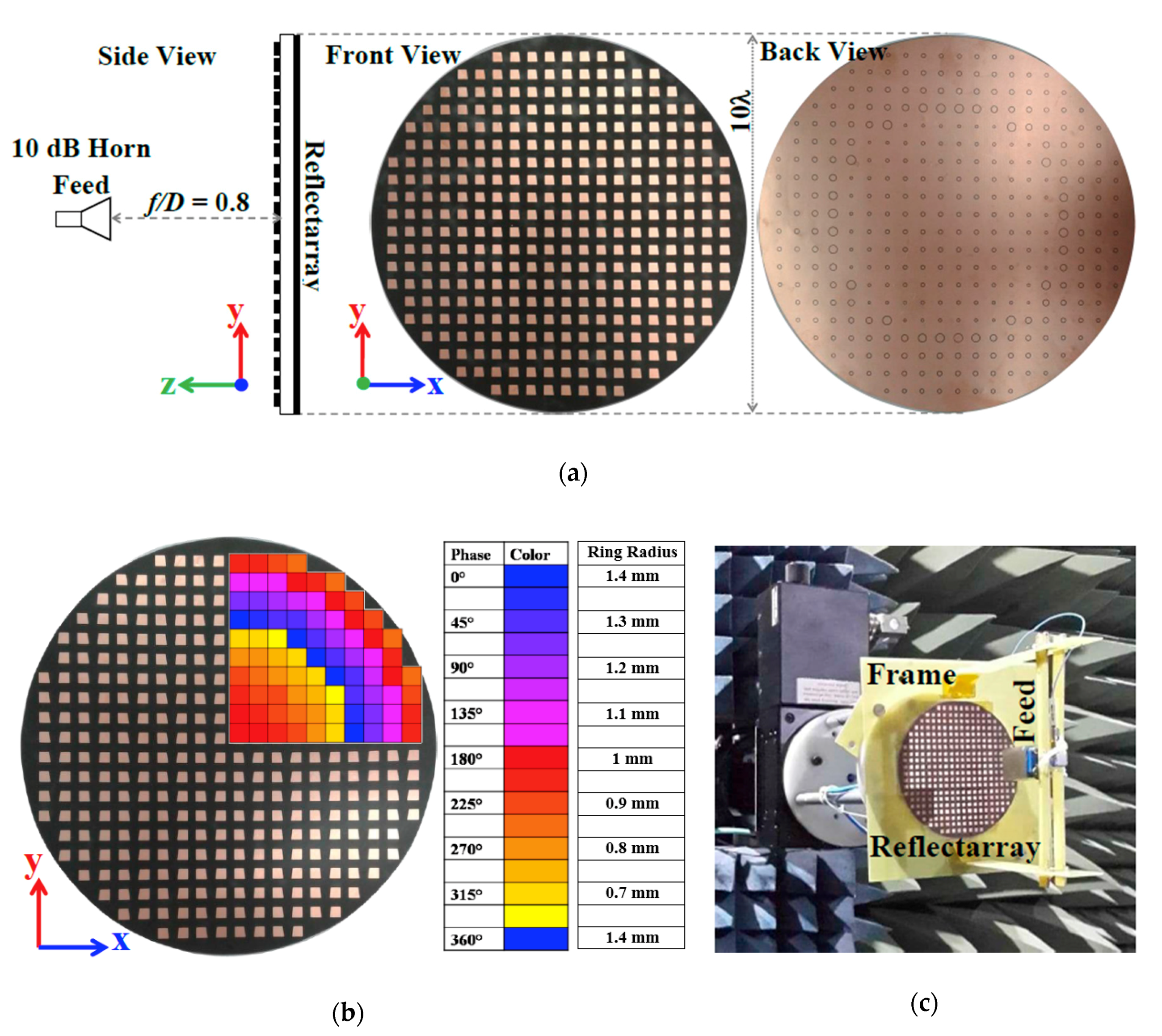
fi is the distance of the selected element from the center of the feed. This mathematical relation has been used to design a 332 element asymmetric patch reflectarray antenna with a variable radius of its ground ring slots that are responsible for attaining an accurate progressive phase distribution. The distance between the asymmetric patches is
λ/2, which is uniform for all the elements on the reflectarray. The variability in the ring slot radius is responsible for making the design periodicity in reference to the feed position to properly eliminate the effect of variable path delays that occur due to a flat surface of the reflectarray. The feed power is selected as 10 dB, which offers a maximum aperture illumination at an
f/D of 0.8 [
11]. A common wet etching fabrication process with high precision is used to make the proposed designs of the asymmetric patch reflectarray antenna. The fabricated designs with different element orientations that are shown in
Figure 8 have been used for experimental verification.
Figure 8a,b depict the two fabricated designs of the asymmetric patch reflectarray without and with mirror orientation of the elements, respectively.
Figure 8b also depicts the progression of the reflection phase on the surface of the reflectarray that is acquired by a variable ring radius for proper collimation of the reflected signals. The ring radius values are also depicted alongside its respective phase values. The size of all the asymmetric patch elements has been kept constant in both of the designs, which is previously mentioned in
Table 1.
The experimental results in comparison with the simulated ones are plotted in
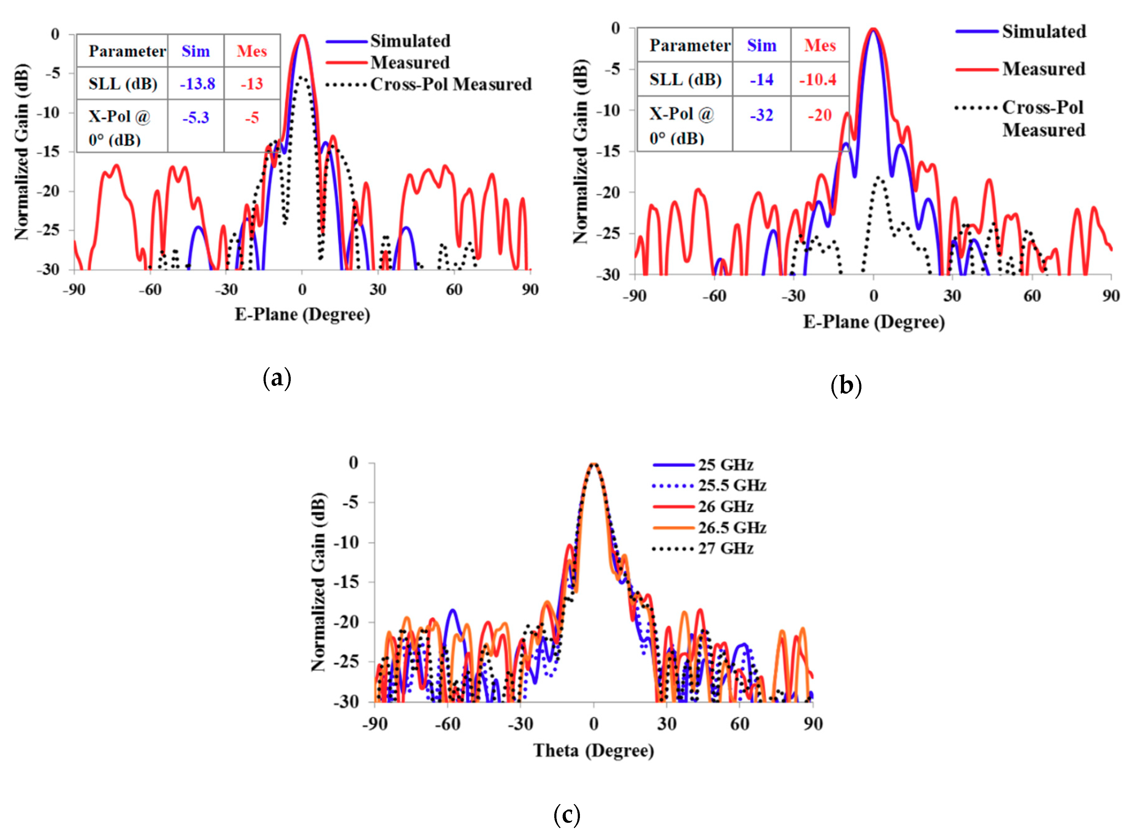
Figure 9. The radiation patterns with the measured graphs of cross polarization of non-mirror and mirror orientation of the asymmetric patch elements have been shown in
Figure 9a,b, respectively. An improvement in the cross polarization level has been noticed from −5 dB to −20 dB when the asymmetric patch elements are mirrored on the surface of the reflectarray. The cross polarization level of −20 dB or lower can be referred to as good isolation between the co-polarization and cross polarization of an antenna [
30]. Simulated cross polarization graphs are ignored here for graph clarity; however, their values are provided. The simulated and measured results are easily comparable with minor discrepancies.
Figure 9c contains measured E-plane graphs for mirror element orientation at different frequencies to show the reliability of the radiation patterns. These results of the asymmetric patch reflectarray antenna have been taken using a vertically polarized incident electric field. Gain versus frequency curves of asymmetric patch reflectarray antenna with vertical polarization are plotted in
Figure 10. It can be seen that the reflectarray without mirror orientation of elements offers higher gain than the reflectarray with mirror orientation of elements. This is due to a higher magnitude of the tilted reflected electric field as compared to a lower magnitude of the vertical electric field, as explained in
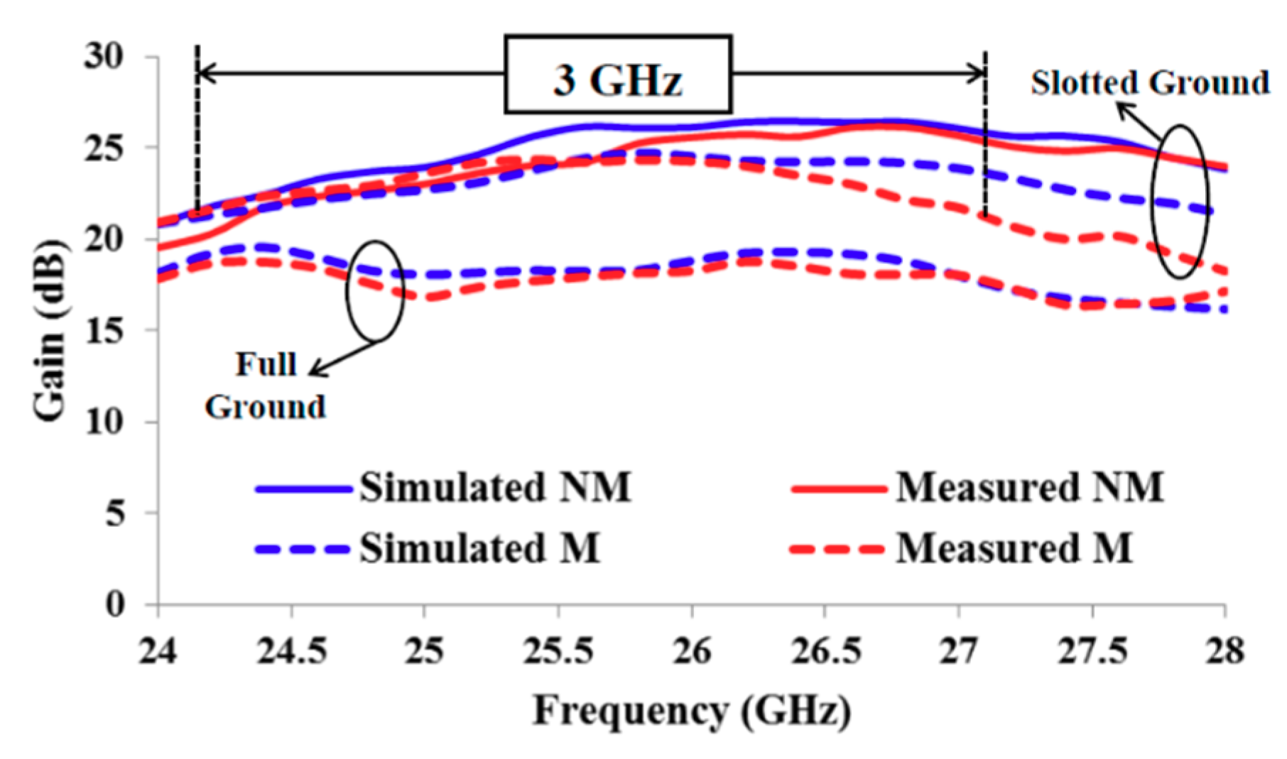
Section 2.1. However, this high-gain performance is idle due to a high cross polarization when elements are not mirrored to each other. A significant improvement in gain is also noticed when a full ground plane is replaced with the circular ring slots. In this case, the gain has been improved from 18.8 dB to 24.4 dB, with increment in aperture efficiency from 7.7% to 28%. The measured 3 dB gain bandwidth of asymmetric patch reflectarray with mirror element orientation is 3 GHz, which covers 75% of the selected frequency band of operation.
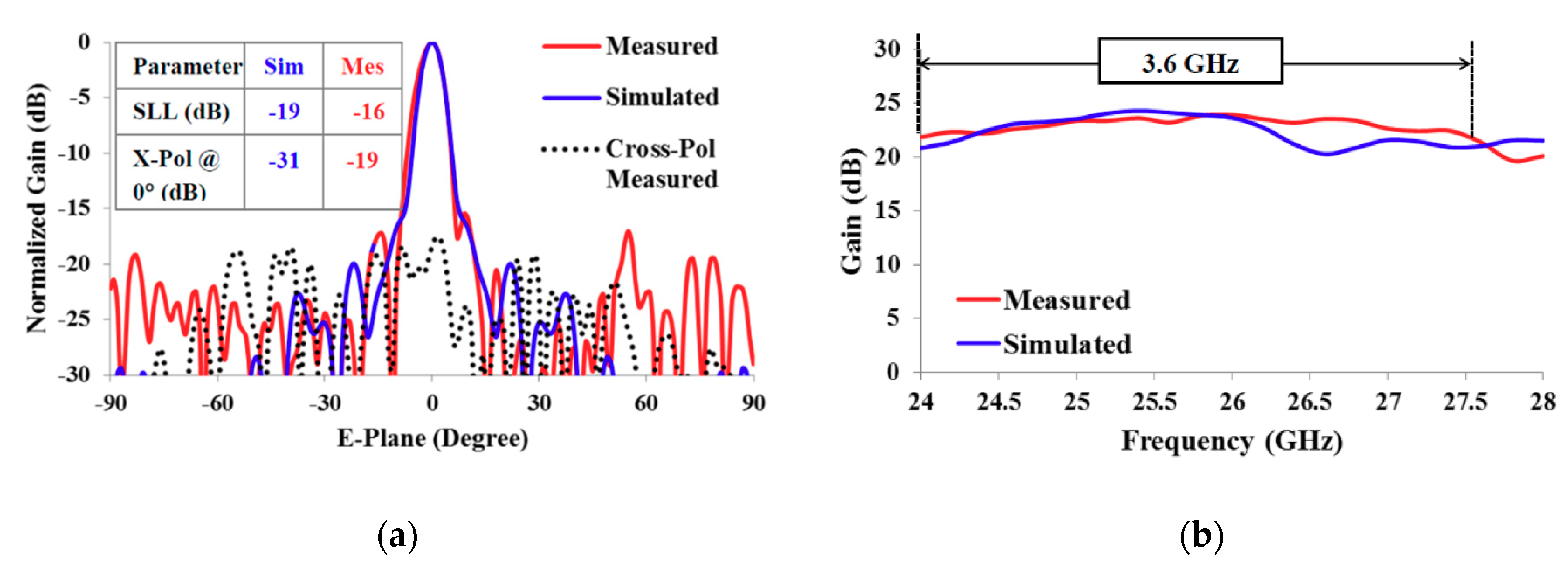
In order to analyze the polarization diversity performance of the asymmetric patch reflectarray antenna of ground ring slots, it is also measured with a horizontally polarized incident electric field. Simulated and measured radiation pattern graphs with mirror orientation of asymmetric patch elements have been plotted in
Figure 11a. The reduction in cross polarization due to mirror orientation of asymmetric patch elements has also been observed in
Figure 11a.
Figure 11b shows gain with respect to the frequency of the asymmetric patch reflectarray antenna with horizontal polarization. A minor reduction in the maximum gain performance of the reflectarray antenna has been observed due to change in its polarization operation. The measured gain with horizontal polarization is 23.9 dB, which is 0.5 dB less than its orthogonal polarization counterpart and offers an aperture efficiency of 25%. Alternatively, the 3 dB gain bandwidth is increased up to 3.6 GHz that is 13.8% at 26 GHz. Moreover, an improvement in the measured side lobe level has also been noticed, as depicted in
Figure 11a. The attained results of the asymmetric patch reflectarray antenna with horizontal polarization also falls well within the range of required parameters needed for 5G communication. It can be said that the proposed reflectarray antenna supports the polarization diversity in its operation and offers good performance with both vertical and horizontal polarization.
4. Receive Signal Strength (RSS) Measurement
In 5G communications, the received signal strength (RSS) and received signal quality (RSQ) are measured to determine the probability of cell selection and handover [
31]. A high value of RSS would mean to have a high power cell with low interference from neighboring cells and low noise level. Therefore, it can also increase the chances of high quality signal reception at the user equipment. A detailed analysis of RSS measurement for 5G base stations with signal coverage improvement is provided in [
32], where two high power horn antennas are used as the transmitter (Tx) and receiver Rx. It is believed that a high value of RSS can provide a high RSQ that is essential for better signal reception in an indoor microcell environment. Therefore, the use of a wideband and high-gain antenna, such as reflectarray, at 5G base station would definitely improve the quality of signal detection at the user equipment. Therefore, the proposed asymmetric patch reflectarray antenna is measured here as an indoor 5G base station and its results are compared with a conventional horn antenna to a draw a fair comparison between them.
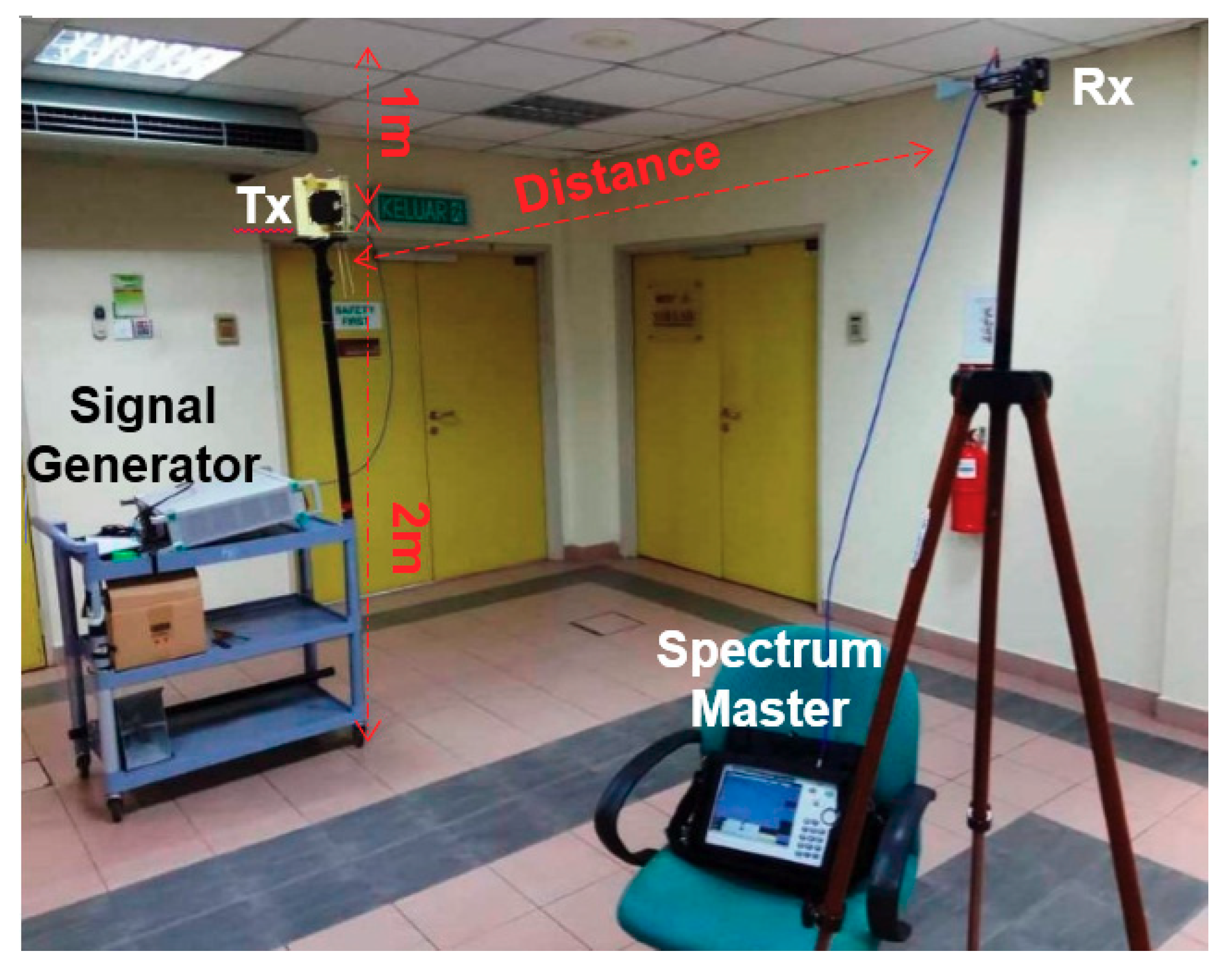
The proposed asymmetric patch reflectarray antenna is tested as an indoor base station to measure the receive signal strength at a variable distance. The overall setup for the measurement is explained in [
31], where a horn antenna was used as a transmitter at the base station, which is replaced here with the reflectarray antenna.
Table 2 summarizes the characteristics and values of the measurement setup. An operating frequency of 26 GHz is selected to measure the dual linear polarized response of the reflectarray antenna. A standard 20 dB horn antenna (CB-28-20-C-KF) is used as a receiver (Rx). The distance between transmitter (Tx) and receiver is varied from 1 m to 16 m with a constant height of 2 m. The minimum distance of 1 m is greater than the minimum far-field distance, which is 2λ, of the Tx antenna. The maximum distance of 16 m is the longest indoor corridor in the Wireless Communication Centre building.
Figure 12 shows the Tx and Rx antennas during the measurements.
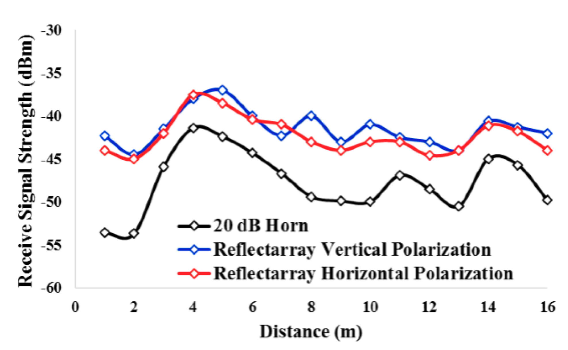
A signal generator (Anritsu MG3694C) is used before the Tx antenna and a spectrum master (Anritsu MS2720T) is connected to the Rx antenna for signal generation and detection, respectively. The main purpose of this study is to analyze the improvement in RSS for an urban indoor microcell sector with a reflectarray antenna. Measured RSS of the asymmetric patch reflectarray antenna and a standard horn antenna as Tx is plotted with respect to the change in distance in
Figure 13. It is observed from
Figure 13 that a significant improvement in RSS is achieved when asymmetric patch reflectarray antenna is used as a Tx. An average of −42 dBm of RSS is observed with asymmetric patch reflectarray antenna, which is almost 5 dBm higher than that of a standard horn antenna. This improvement in RSS is due to the higher gain of asymmetric patch reflectarray antenna as compared to a standard horn antenna. Moreover, the asymmetric patch reflectarray antenna offers almost the same RSS response with dual linear polarization operation.
A higher RSS than a conventional horn antenna could also make device discovery easier in an urban microcell environment [
31]. This measurement has also been repeated with the operating frequencies of 25 and 27 GHz, where a similar RSS response has been found. This analysis proves that, a good signal reception and detection at user equipment is expected if the proposed asymmetric patch reflectarray antenna is used as the 5G base station antenna. The only limitation associated with asymmetric patch reflectarray antenna is its narrow beamwidth, which tends to increase the number of sectors in a microcell. This limitation could be avoided by using a beamsteering strategy in the reflectarray antenna [
6,
19]. A wide reflection phase range, as in asymmetric patch reflectarray, would be beneficial for acquiring wide angle beamsteering operation.
5. Comparison of Asymmetric Patch Reflectarray Antenna with Other Related Works
The proposed design of asymmetric patch reflectarray antenna can also fall into the category of matasurface or frequency selective surface (FSS) due to its slotted ground structure. The latest technological advancement in metasurfaces with enhanced features are reported in [
33,
34]. The reported works of metasurfaces apply patch based dual layer technique to acquire beamsteering in reflection and transmission of the incident signals. Alternatively, this work proposes a single reflecting layer of asymmetric patches of ground ring slots for fixed beam operation. The two layer structure of metasurfaces are designed in such a way to improve the transmission of the incoming signals from the metasurface layer in both directions with minimum reflections. On the other hand, the proposed design of the reflectarray antenna offers maximum possible reflections from the patch based layer. The proposed asymmetric patch reflectarray antenna have ring slots in its ground plane, which could still pass some portion of the incident signals as transmission, but amount of this back radiating transmission would be very small as the reflected signal has a very high gain. Apart from some differences, the metasurfaces and the reflectarrays both use the same technique of patch based phase shift to control the direction of the transmitted or reflected signals. Additionally, if further layers are added in the proposed reflectarray design and its ground ring slots are widen further then it can be featured as a transmitive structure to offer features like a metasurface.
The proposed asymmetric patch reflectarray antenna is developed from the square patch reflectarray antenna. Asymmetry in the patch makes it to attain a wider reflection phase range and wider bandwidth performance as compared to an equivalent aperture square patch reflectarray antenna. In order to make a fair comparison of this work with other reflectarray antennas, an equivalent aperture square patch reflectarray antenna has been designed and experimentally tested. The square patch reflectarray antenna offers a measured 3 dB gain bandwidth of 6.9%, which is 4.6% lower than that of the asymmetric patch reflectarray antenna. The 5G research based on the reflectarray antenna is still very new and in its initial stages. There are only a few related and reputable works available in the literature that are summarized and compared with this work in
Table 3. A most recent work proposing dual band reflectarray operation for 5G communication with dual linear polarization is reported in [
35]. This dual band design uses two different elements for two different polarization and holds four elements in one unit cell for dual band operation. The asymmetric patch reflectarray offers a higher gain and wider bandwidth than this dual band design by using just a single patch element in one unit cell. A similar work proposed in [
36] also uses the same technique for dual band operation, but with a single polarization. This work also has a narrower bandwidth performance than the asymmetric patch reflectarray antenna.
Moreover, the asymmetric patch reflectarray attains a wider reflection phase span with a lower design complexity than these two dual band designs. Two other similar works reported in [
4] and [
19] offer good bandwidth and gain performance with low design complexity, but for just a single polarization operation. Moreover, these two works present a reflectarray antenna with a conventional type of element, such as circular ring and rectangular patch, which offer a very narrow reflection phase range. In contrast, this work proposes a new asymmetric patch element with a wide reflection phase range for high-gain reflectarray operation with comparatively less number of elements. The asymmetric patch reflectarray antenna has also been compared with a transmitarray [
37] and a full metallic reflectarray [
38] that were proposed for 5G operation at 60 and 26 GHz respectively. Four different patches in five different layers make single polarized transmitarray an electrically large and very complicated structure as compared to the current work that operated at dual linear polarization. A full metallic design of a metallic reflectarray removes the dielectric losses and improves its efficiency performance. However, it still attains a lower gain and narrower bandwidth performance as compared to the asymmetric patch reflectarray antenna. This is because of a narrow reflection phase range of the unit cell of the metallic reflectarray antenna. On the other hand, the current work of the asymmetric patch reflectarray antenna has a wider reflection phase span with dual linear polarization operation. Moreover, this is the first time a reflectarray antenna is tested for RSS measurements with dual linear polarization operation for comparison with a standard horn antenna that is normally used for 5G based microcell measurements. Consequently, it can be said that the asymmetric patch reflectarray antenna proposed for 5G communication in this work, attains comparably better performance with low design complexity as compared to the related works of the published literature.

 ,
, 


