Article

Improved Indirect Model Predictive Control for Enhancing Dynamic Performance of Modular Multilevel Converter

School of Electrical and Electronic Engineering, Chung-ang University, Seoul 06974, Korea
*
Author to whom correspondence should be addressed.
Electronics 2020, 9(9), 1405; https://doi.org/10.3390/electronics9091405
Submission received: 5 August 2020 / Revised: 24 August 2020 / Accepted: 28 August 2020 / Published: 31 August 2020
(This article belongs to the Section Power Electronics)

Abstract

:
Model predictive control has become a tremendously popular control method for power converters, notably a modular multilevel converter, owing to the ability to control various objectives at once with a particular cost function and prominent dynamic performance. However, the high number of submodules in cascaded control means that the model predictive control for the modular multilevel converter suffers from a computational burden. Several approaches focused on reducing the computational burden based on limiting the number of possible switching states (possible choices) to be evaluated at each sampling instant. The dynamic performance of the modular multilevel converter is degraded in a transient state, despite the reduced computational burden. This paper presents an improved indirect model predictive control method to reduce the computational burden and enhance the dynamic performance. The proposed approach considers the steady-state and transient state individually and applies a different range of choices for each specific case. The range of choices during the steady-state is limited in order to reduce the computational burden without deteriorating the output quality, whereas the number of choices will be increased during the transient state to guarantee dynamic performance. The results that were obtained by implementing an experiment on a laboratory setup of a single-phase modular multilevel converter are presented in order to verify the proposed approach’s effectiveness. From the experimental setup, the computational time in the proposed approach was reduced by about 75% when compared with the conventional indirect model predictive control, whereas keeping fast dynamic performance.

1. Introduction

As a result of a notably modular structure, uncomplicated scalability, excellent harmonic performance, and the most potential for high-power applications due to cascaded topology, a modular multilevel converter (MMC) has emerged as one of the outstanding topologies for medium voltage, high power energy conversion applications [1,2,3]. Despite offering numerous advantages, it suffers from challenging control [2,3]. Controlling an MMC requires a proper scheme to acquire various targets, such as the adequate magnitude and frequency of output currents, suppression of circulating current, and equality of submodule (SM) capacitor voltages. The classical control techniques achieve these objectives by using proportional-integral (PI) [4] and proportional-resonant (PR) [5] controllers for the current control loop, an SM voltage balancing approach or balancing controller, and a modulator with a phase-shifted [4,6,7] or level-shifted pulse-width modulation [8,9] to control the MMC. However, these classical control methods are typically based on linear controllers and complex cascaded configurations. These characteristics result in problems when optimizing system performance and difficulties when designing control parameters. Additionally, the dynamic performance of classical control methods is unsatisfactory [3,10].
In the latest years, model predictive control (MPC) has been concerned, notably regarding the control of MMC thanks to its feature in controlling a couple of targets simultaneously with a single cost function and advanced dynamic performance [10,11,12,13,14,15]. The fundamental idea of an MPC is to assess all viable switching states of a converter to attain the best one that results from the cost function’s minimum value. The mentioned MPC technique refers to direct MPC [10], wherein 22N possible switching states are assessed in each sampling instant, where N is the number of SMs in each arm. The number of viable switching states increases exponentially as the number of SMs increases despite its straightforward implementation. This drawback renders applying direct MPC challenging in a large-scale MMC system. A proposed indirect MPC was studied in [16] that could decouple the control of the SM capacitor voltages from the cost function by the usage of a voltage sorting method in order to resolve this problem. The MPC is accountable for determining the number of inserted SMs in the upper and lower arms. At the same time, the capacitor voltage sorting algorithm could select which SM should be inserted or bypassed to maintain equality in the SM capacitor voltages. Although indirect MPC allows the number of control actions of MPC to be reduced to (N + 1)2 when compared to direct MPC, the calculation still requires significant effort to accommodate a large number of SMs in an MMC system.
Furthermore, various approaches have been proposed recently to address the computational burden for the MMC [17,18,19,20,21,22]. The method that is proposed in [17] regulates objectives by dividing them into three separate cost functions that correspond to the output current, circulating current, and SM capacitor voltage. Based on certain conditions that are applied to each control objective, this approach can decrease the number of control actions in every sampling instant. Another technique that is presented in [18] uses tolerance bands of capacitor voltage fluctuations and output voltage level to change the number of inserted SMs in one phase. A fast MPC method (FMPC), based on indirect MPC, limits the range of choices to two or three control actions using only the neighboring output voltage level related to the last one [19]. This control scheme selects a proper output voltage level based on an exact look-up table, including all possible inserted SMs. In [20,21], a preselection method is proposed to lessen the number of control actions in every sampling instant. These methods use the correspondence among the output voltage level at the current instant and the closet output voltage levels at the following step, preselect the number of inserted SMs to be evaluated in the subsequent sampling instant. Particularly, in [21], a simplified indirect MPC reduces the number of control actions in every switching period significantly without overly deteriorating other performances. However, the reduction of possible switching states results in a lower dynamic performance, because the MPC requires more time to accurately track the reference value by only considering three possible choices for the number of inserted SMs when compared to the conventional indirect MPC, which evaluates all possible inserted SMs or possible choices. In [16], the dynamic performance comparison between the conventional indirect MPC and an indirect MPC with a reduced number of switching control actions shows that the indirect MPC with a reduced number of switching control actions has a slower response due to the limitation of switching states. Additionally, the author in [23] shows that the reduced number of evaluating vectors in cascaded H-bridge inverter requires more steps to track the reference values, resulting in a slower dynamic response as compared with the conventional MPC method. Thus, the reduction of the number of switching control actions results in the rate of changes of switching states is limited. This leads to slower dynamic performance compared to the conventional indirect MPC. Therefore, an approach can guarantee both the reduction of computational burden and the dynamic performance that should be required.
An indirect MPC with reduced computational burden and improved dynamic performance for MMC, in which the steady-state and transient state are investigated individually, are proposed herein. During the steady-state, only the optimal number of inserted SMs at the present step, and two adjacent choices are considered based on predefined conditions. Nevertheless, in the transient state, more choices are available for the number of inserted SMs than those used in the steady-state for better dynamic performance, but fewer choices are available when compared with the total possible number of SMs. The proposed technique, as compared with the conventional indirect MPC [16] that uses all possible switching states, can reduce the computational burden and improve the dynamic performance compared to the simplified indirect MPC in [21]. The focus of this approach is based on the practical implementation of the MPC; therefore, an experimental setup using single-phase seven-level MMC is operated in order to verify the proposed technique’s effectiveness. The conventional indirect MPC and simplified MPC are chosen and experimentally implemented to compare the three control schemes’ performances.
This paper is prepared, as follows: Section 2 offers a brief introduction of the elemental structure and operation of the MMC, the conventional indirect MPC, and previous indirect MPC approaches to reduce the computational burden. Section 3 clarifies the proposed technique in detail regarding the reduction of the computational burden and improving the dynamic performance. Section 4 presents the experimental setup and results, whereas comparing and analyzing the dynamic performance among the three control schemes, followed by the conclusions in Section 5.

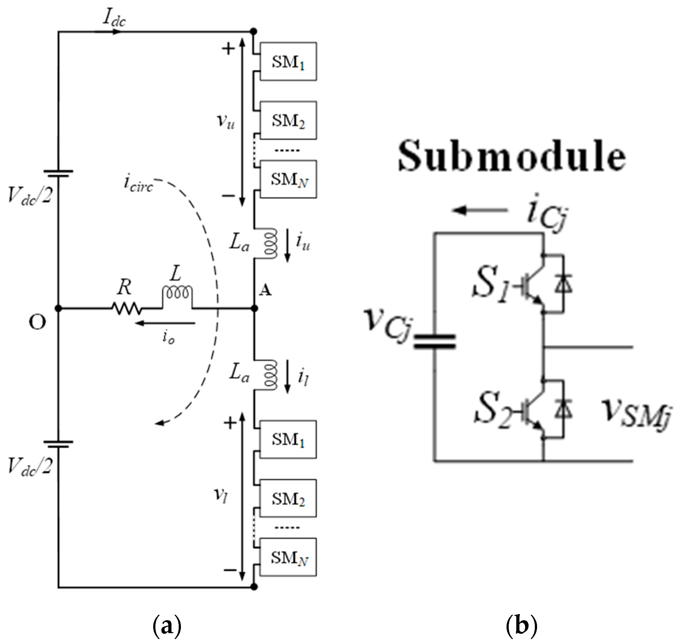
2. Theoretical Background

2.1. Conventional Indirect MPC

Figure 1 shows a representative arrangement of a one-phase MMC, which includes two arms that form one converter phase. The upper and lower arms are characterized by using subscripts “u” and “l”, respectively. Each arm incorporates N SMs linked in series with an inductor La that plays a role in limiting the arm current. A half-bridge SM structure in Figure 1b is applied in this investigation because of its straightforwardness and low power-loss features. The half-bridge SM can only produce zero and positive voltages relying on the state of its two complementary switches S1 and S2.
In Figure 1, making use of Kirchhoff’s current law to the MMC circuit means that the output current io equation can be acquired, as follows:
i o = i u i l ,    
where iu and il are the upper arm current and lower arm current, respectively.
The circulating current can be deduced from the upper and lower arm currents [1,2,3], as follows
i c i r c = 1 2 ( i u + i l )
The voltage relationship of the MMC in Figure 1, as stated by Kirchhoff’s voltage law, can be expressed as
V d c 2 v u L a d i u ( k ) d t R i o L d i o ( k ) d t = 0 ,
V d c 2 + v l + L a d i l ( k ) d t R i o L d i o ( k ) d t = 0 ,
where vu and vl represent the upper and lower arm voltages, respectively.
Adding (3) and (4) and substituting for io from (1), the dynamic equation of the output current is acquired as
d i o ( k ) d t = ( 1 2 L + L a ) [ v l ( k ) v u ( k ) 2 R i o ( k ) ] .
Similarly, the dynamic equation of the circulating current can be figured out by way of subtracting (3) from (4) and substituting for icirc from (2):
d i c i r c ( k ) d t = ( 1 2 L a ) [ V d c v u ( k ) v l ( k ) ] .
The discrete-time domain mathematical model of the output current and circulating current can be acquired using the Euler method [24], provided as follows:
i o ( k + 1 ) = ( T s p 2 L + L a ) ( v l ( k ) v u ( k ) ) + ( 1 2 R T s p 2 L + L a ) i o ( k ) ,
i c i r c ( k + 1 ) = ( T s p 2 L a ) [ V d c v u ( k ) v l ( k ) ] + i c i r c ( k ) .
The cost function g, which is described by (9), can be used to decide the finest number of inserted SMs in the next sampling instant.
g = w 1 | i o * ( k + 1 ) i o ( k + 1 ) | + w 2 | i c i r c * ( k + 1 ) i c i r c ( k + 1 ) | ,
where i o * ( k + 1 ) and i c i r c * ( k + 1 ) are the predicted output current and circulating current, respectively, and w1, w2 are the respective weighting factors. Figure 2 depicts the conventional indirect MPC method.
Evaluating all possible SM choices to determine the optimal one results in the smallest value for the cost function. The voltage sorting algorithm that is shown in Figure 3 collects the information about the optimal number of SMs nu and nl. The direction of the upper arm current and lower arm current and the magnitude of the capacitor voltages vC are taken into consideration to select which SMs should be inserted or bypassed. Subsequently, the switching states are produced to be sent to the MMC, which are carried out on the sampling instant.

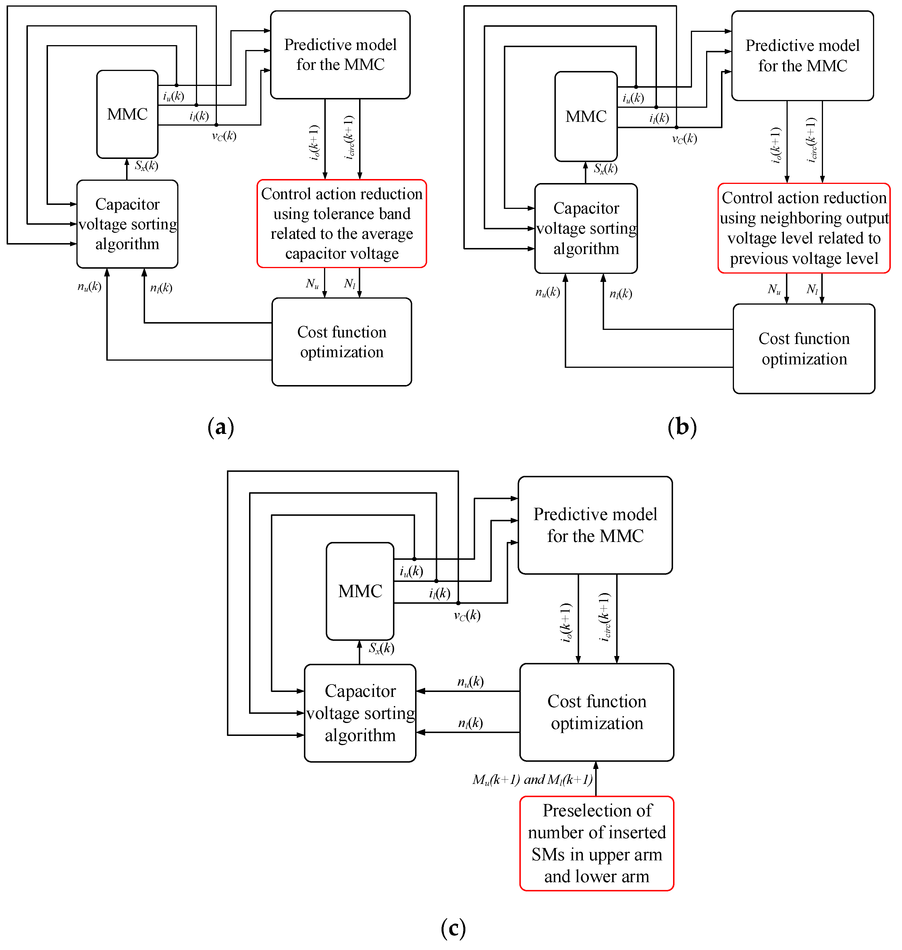
2.2. Recent Indirect MPC Approaches to Reduce the Computational Burden

In addition to the conventional indirect MPC, the author in [18] proposed a control scheme, named voltage-level-based MPC. Different from the conventional indirect MPC, the voltage-level-based MPC reduces the computational burden by narrowing the possibility of the total number of inserted SMs. Different combination of nu and nl results in different value of the sum and difference arm voltages, as follows:
v = n u × v C u + n l × v C l
v = n u × v C u n l × v C l    
The possibilities of nu and nl in the voltage-level-based MPC can be acquired by replacing v and v in (10) and (11) with V d c and difference arm voltage reference v * and using the tolerance band that is related to the average capacitor voltage
N u = [ r o u n d ( V d c + v * 2 v C u ( 1 + σ ) , , r o u n d ( V d c + v * 2 v C u ( 1 σ ) ]
N l = [ r o u n d ( V d c v * 2 v C u ( 1 + σ ) , , r o u n d ( V d c v * 2 v C u ( 1 σ ) ]
where σ is the tolerance band around the average capacitor voltage. The block diagram of voltage-level-based MPC is depicted in Figure 4a. The control scheme in [18] is implemented in the MMC system with N = 200, but the relationship between the tolerance band around average capacitor voltage, reduction of the number of control options, and the output performance is not discussed. Besides, the dynamic performance is not analyzed in detail when comparing with the conventional indirect MPC or other MPC approaches.
Figure 4b illustrates the block diagram of FMPC [19]. The FMPC significantly reduces computational burden as compared with the conventional indirect MPC by only evaluating neighboring output voltage level corresponding to the previous one. The FMPC selects an appropriate output voltage level on the basis of an exact look-up table consisting of all possible number of inserted SMs. Although this control scheme significantly reduces the computational burden, there has not been in detail addressed for the MMCs with a 2N + 1 output voltage level, where the intermediate output voltage level increases the complexity of FMPC. The dynamic response obtained from the FMPC method is slower than the conventional indirect MPC. Besides, the author in [19] does not discuss the circulating current control problem that arises in a large number of SMs.
The authors in [20,21] reduce the range of the possible number of inserted SMs in the upper and lower arms by predicting the evaluating number of inserted SMs based on predefined conditions. The range of preselected number of inserted SMs is narrowed when compared with evaluating all possible number of inserted SMs in the upper and lower arms. Especially in [21], the author uses a predefined condition regarding the circulating current control to further reduce the number of control actions. From (8), it can be said that the circulating current is controlled by the sum of arm voltages. By combining (8) and (10), the predicted circulating current can be obtained, as follows:
i c i r c ( k + 1 ) = ( T s p 2 L a ) [ V d c   ( n u × v C u + n l × v C l ) ] + i c i r c ( k ) .
It can be noticed that the circulating current can be controlled by the different number of inserted SMs. By using this condition combining with the redundant number of inserted SMs, the simplified indirect MPC in [21] can considerably reduce the computational burden. Figure 4c illustrates the block diagram of the simplified indirect MPC. Different from [18,19], the simplified indirect MPC narrows the range of the possible number of inserted SMs in the upper and lower arms without using the look-up table. However, the range of the possible number of inserted SMs needs to be considered following the number of SMs to guarantee the circulating current controllability before the implementation.
Table 1 presents the comparison among the previous MPC approach to reduce the computational burden in case of a relatively large number of SMs (N = 200) with a description of the idea, requirements, capability of controlling circulating current, and reduction of computational burden capability.

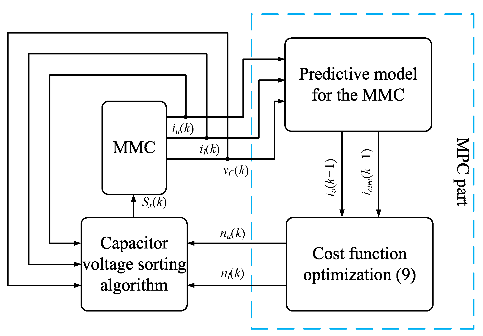
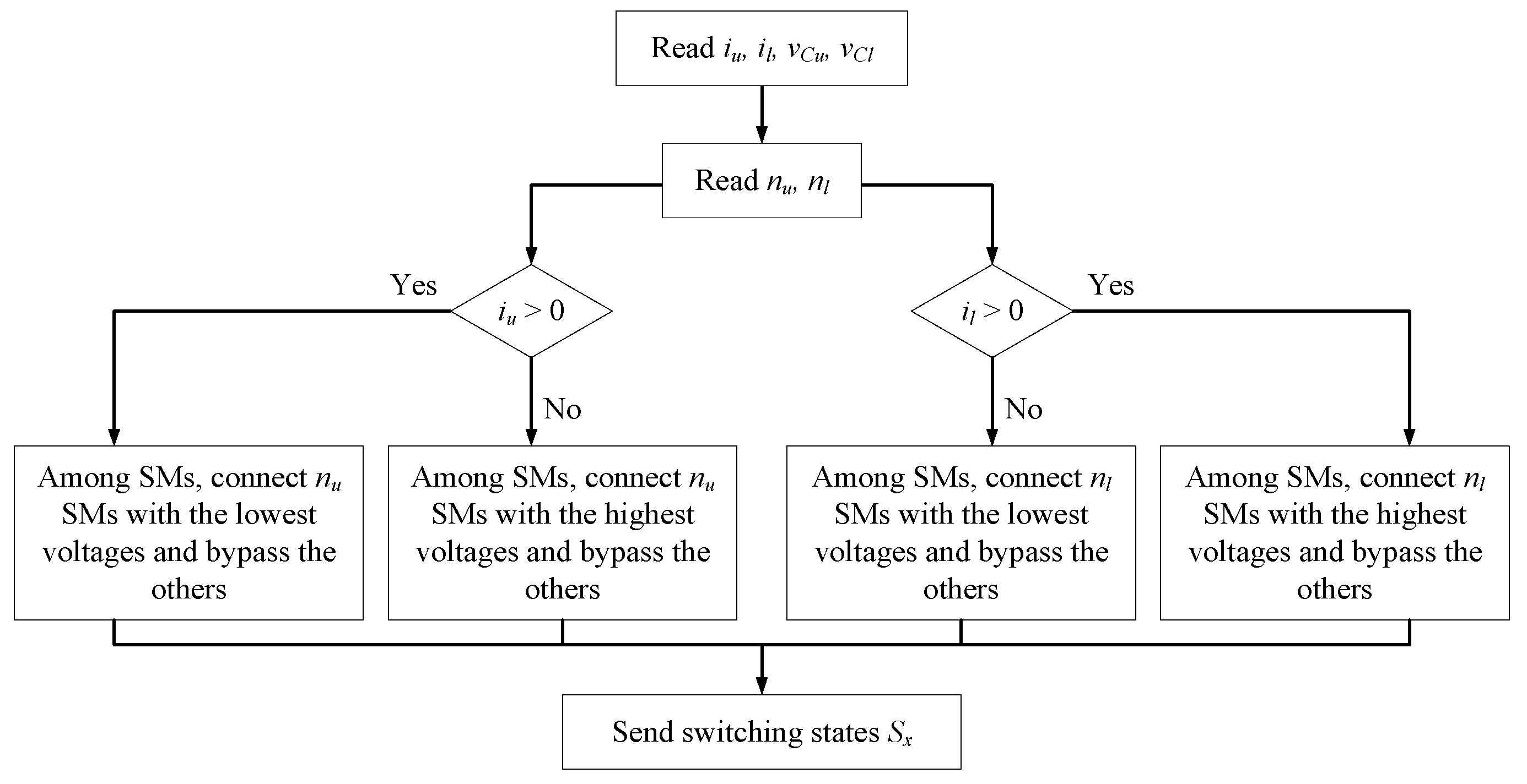
3. Proposed Indirect MPC

The proposed method reduces the computational burden and improves the dynamic performance in comparison to the conventional indirect MPC and simplified indirect MPC. Figure 5 illustrates a block diagram of the proposed indirect MPC. The control of the output current and circulating current is realized in the same manner as the conventional indirect MPC previously described using the cost function g in (9), whereas the sorting algorithm selects the switching states of every SM to maintain the SM capacitor voltage at a nominal value.

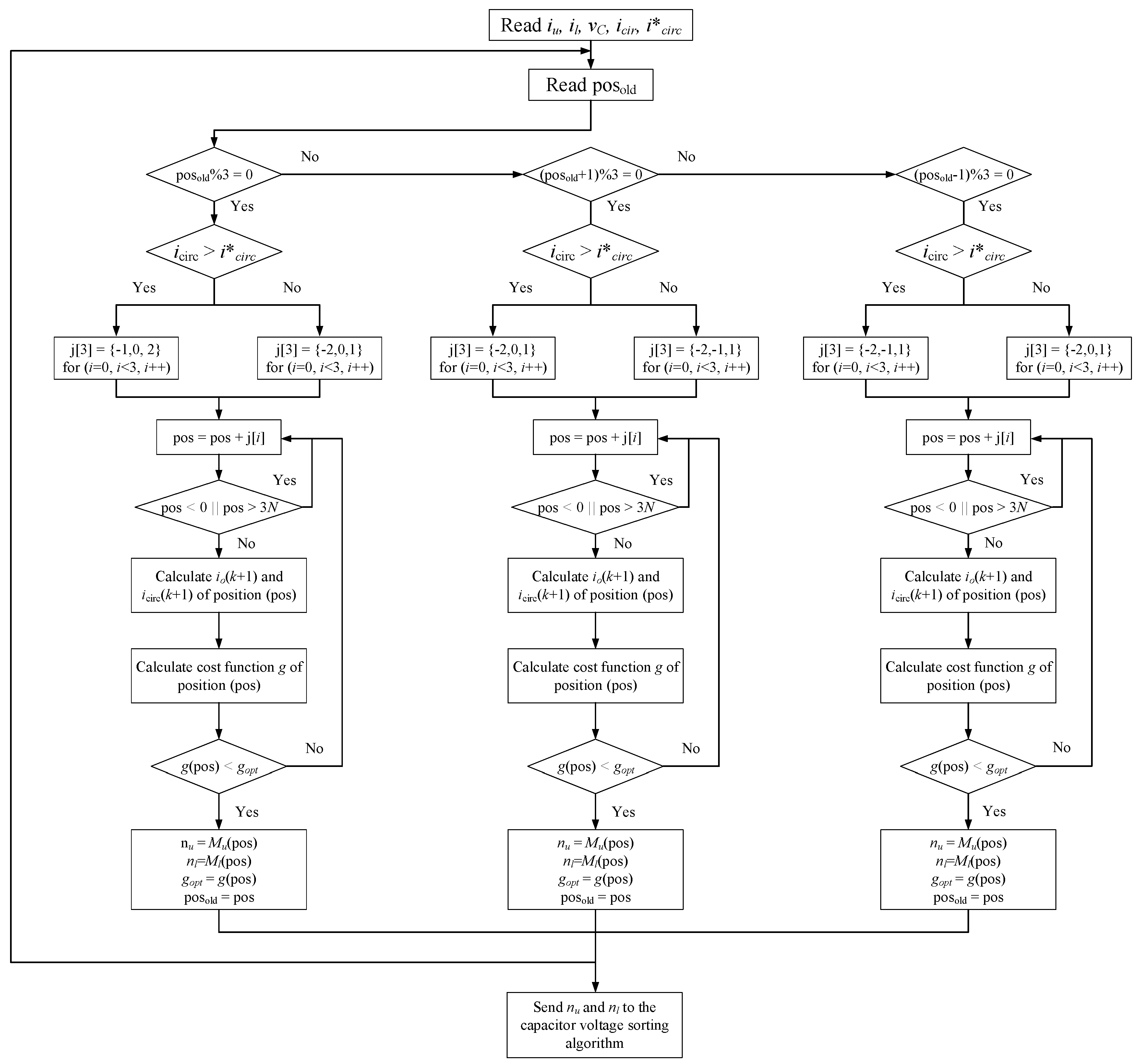
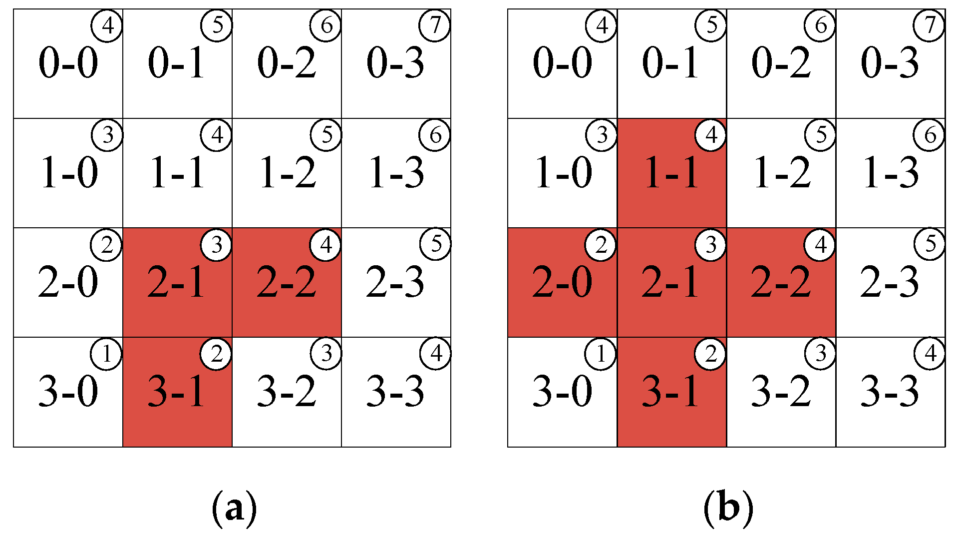
3.1. Reduction of Calculation Burden

The proposed method reduces the computational burden and improves the dynamic performance in comparison to the conventional indirect MPC and simplified indirect MPC. Figure 5 illustrates a block diagram of the proposed indirect MPC.
Although the number of control actions within each sampling instant can be reduced while using indirect MPC, as compared with direct MPC ((N + 1)2 and 22N), calculating with a vast number of SMs still requires significant effort. In this subsection, a method is proposed in order to reduce the number of control actions. The basic idea behind the proposed method is to narrow the range of the number of inserted SMs at every switching instant.
A unique characteristic of the MMC is that it can generate an N + 1 or 2N + 1 output voltage level with N SMs per arm. The 2N + 1 output voltage level can be generated by varying the total number of inserted SMs in the upper and lower arms by N − 1, N, and N + 1 [25]. Notably, the N−1 and N + 1 choices generate the identical output voltage level [25,26]. It is apparent that certain correspondences exist between the number of inserted SMs and the output voltage level, which is described as
l = n l n u + N + 1
Figure 6a shows the correlation among the output voltage level and the number of inserted SMs, where the two numbers in the square represent the number of inserted SMs in the upper arm and lower arm, separately, and the number in the circle represents the output voltage level.
In the conventional indirect MPC method, the range of evaluation processes in the MPC strategy includes all possible inserted SMs for the single-phase seven-level MMC (N = 3) used in this experiment. By only using N − 1, N, and N + 1 inserted SM choices in total, the range of the evaluation process can be narrowed from (N + 1)2 to (3N + 1) choices, as shown in Figure 6b, where the possible number of inserted SMs is presented as blue squares in this case. A transition of the output voltage level is considered to further narrow the range of the evaluation process. The possible number of inserted SMs that corresponds to the previous optimal one will be evaluated in order to ensure that the transition of the output voltage level is limited by one. This avoids an unexpected high dv/dt output voltage and helps to limit the range of the evaluation process to five choices. Assuming that the previous number of inserted SMs in the upper arm and lower arms are nu = 2 and nl = 1, respectively, the possible number of inserted SMs that will be evaluated is the previous one and the four nearest choices according to the output voltage level condition in Figure 6c, which are depicted by green squares. By combining an additional condition regarding the instantaneous value of the circulating current, the possible number of inserted SMs can be limited to three choices. According to [21,26], the effect of N − 1 and N + 1 inserted SMs on the circulating current is opposite, even though they produce the identical output voltage level. The N − 1 inserted SMs tend to increase the circulating current, whereas the N + 1 inserted SMs reduce the circulating current. Because of this, when the circulating current is higher than the reference value, only N + 1 choices are considered and vice versa. Figure 6d depicts the reduced possible number of inserted SMs. Assuming that the previous numbers of inserted SMs in the upper arm and lower arm are nu = 2 and nl = 1, respectively, and i c i r c > i c i r c * ( i c i r c * =   I d c = P / V d c ) [16], the possible number of inserted SMs that will be assessed is located in the orange squares. Those guarantee three conditions: the total number of inserted SMs will vary between only N − 1, N, and N + 1; the possible number of inserted SMs in the nearest choices corresponds to the previous optimal one, whereas the transition of the output voltage level is limited to one; the circulating current requirement is satisfied.
Figure 7 depicts a control diagram of the MPC in the steady-state according to the analysis above. The proposed method is applied to an experimental implementation with a seven-level output voltage MMC that contains three SMs in each arm (N = 3); however, it can be easily applied in the MMC with a different number of SMs. The proposed algorithm’s implementation starts by determining the position of the previous optimal number of inserted SMs (posold) in the look-up table. It should be noted that the value of posold defaulted to zero before the iteration. The elements in the array j are used to adjust position (pos) of the possibility of the number of inserted SMs in the upper and lower arm. Based on predefined conditions, the position of the present optimal number of inserted SMs will be located in the look-up table, and then the corresponding possible number of inserted SMs will be assessed in order to determine which is will be used.

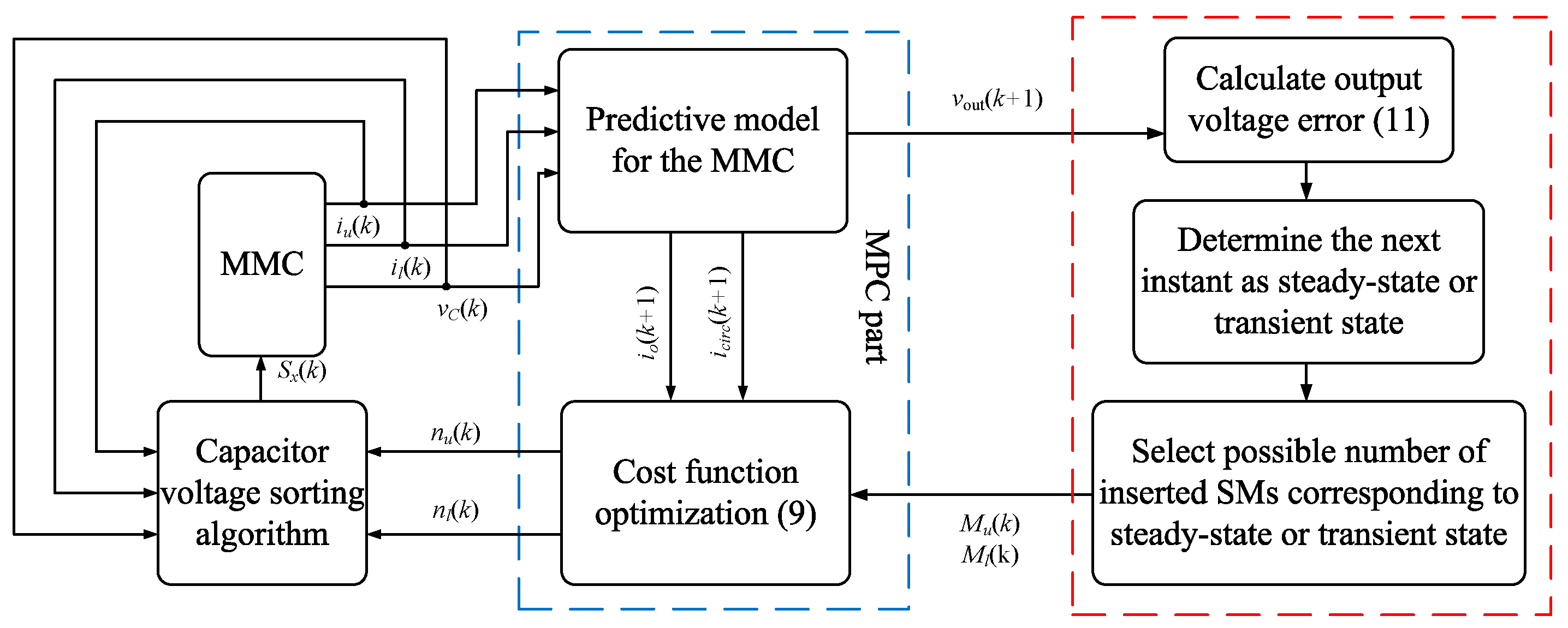
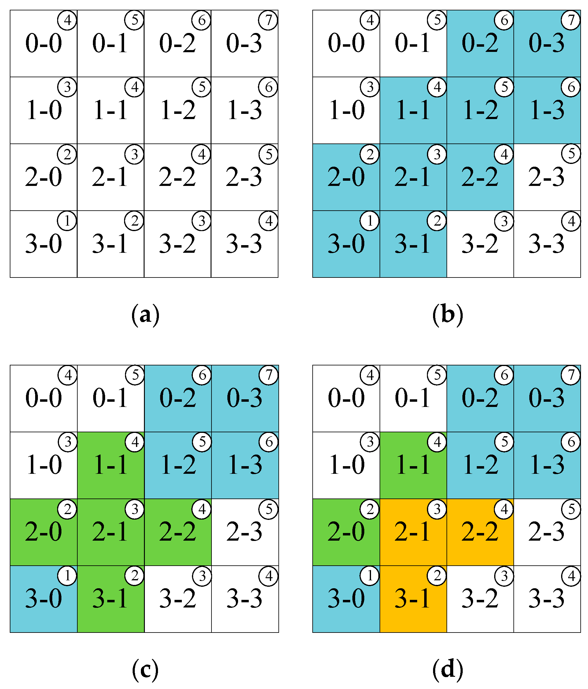
3.2. Improved Dynamic Performance Approach

In terms of the transient state, the proposed approach considers a new range for the number of inserted SMs that contains more choices than those for the steady-state to enhance the dynamic performance of the MMC. In the steady-state case, the voltage step between the present output voltage and the next sampling instant one is either 0 or Vdc/2N. By contrast, this voltage step could be higher than Vdc/2N, owing to an abrupt change in the output current reference value. Therefore, the difference in the output voltage value is used to indicate whether the next instant is a steady-state or transient state, as defined in (16)
V o u t = | v o u t ( t ) v o u t ( t + T ) |
where v o u t ( t ) and v o u t ( t + T ) are the present and next instant values of the output voltage, respectively. If V o u t Vdc/2N, the next instant is determined as the steady-state, whereas a transient state will occur if V o u t > Vdc/2N.
After determining the next instant as the steady-state or transient state, the proposed approach decides which range of the number of inserted SMs need to be used. If the following instant is a steady-state, then the possible number of inserted SMs is limited to three choices, as in Figure 8a. Meanwhile, the number of possible choices in the transient state will be increased by adjusting the conditions mentioned above. This subsection analyzes the changes.
For different cases in which the number of possible choices is adjusted, we assume that the previous finest number of inserted SMs in the upper and lower arms are nu = 2 and nl = 1, respectively. By removing the circulating current condition, the range of evaluation processes increases from three to five choices, as in Figure 8b. Meanwhile, six inserted SM choices will be available if we retain the circulating current condition but remove the requirement regarding the total number of inserted SMs and the transition of the output voltage level, as shown in Figure 8c. Finally, by using only the nearest number of inserted SMs, the number of choices, in this case, will be nine, as shown in Figure 8d.
Figure 9 shows the magnified simulation waveform of the output current and voltage, and the total number of inserted SMs during the transient state of a magnitude change in the reference current by using the improved dynamic performance control. It can be observed that, at this time, the difference in the output voltage is indicated; the number of possible choices in the transient state is changed, resulting in a different selection of the number of inserted SMs.
Table 2 summarizes the comparison of the number of control actions between the proposed method and previous approaches for the case of a single-phase seven-level MMC used in the experiment.

4. Experimental Setup and Results

4.1. Experimental Setup

The proposed technique’s performance was validated by means of accomplishing an experiment on a single-phase MMC laboratory setup; Table 3 shows its setup parameters. Figure 10a,b present the MMC laboratory prototype configuration and photographs, respectively. The single-phase MMC laboratory prototype incorporates three half-bridge SMs in each arm that generates seven levels of output voltage (N = 3). For this investigation, the experiment was conducted using Texas Instruments’ TMS320F28335 digital signal processor (DSP). Figure 10c depicts the digital control system that is used in the experiment. Initially, the capacitor voltages in the upper and lower arm currents were measured through current sensors and voltage sensors, respectively. Subsequently, they were transmitted to the DSP in order to execute the control algorithm. Three methods were investigated: the proposed method, simplified indirect MPC, and conventional indirect MPC.

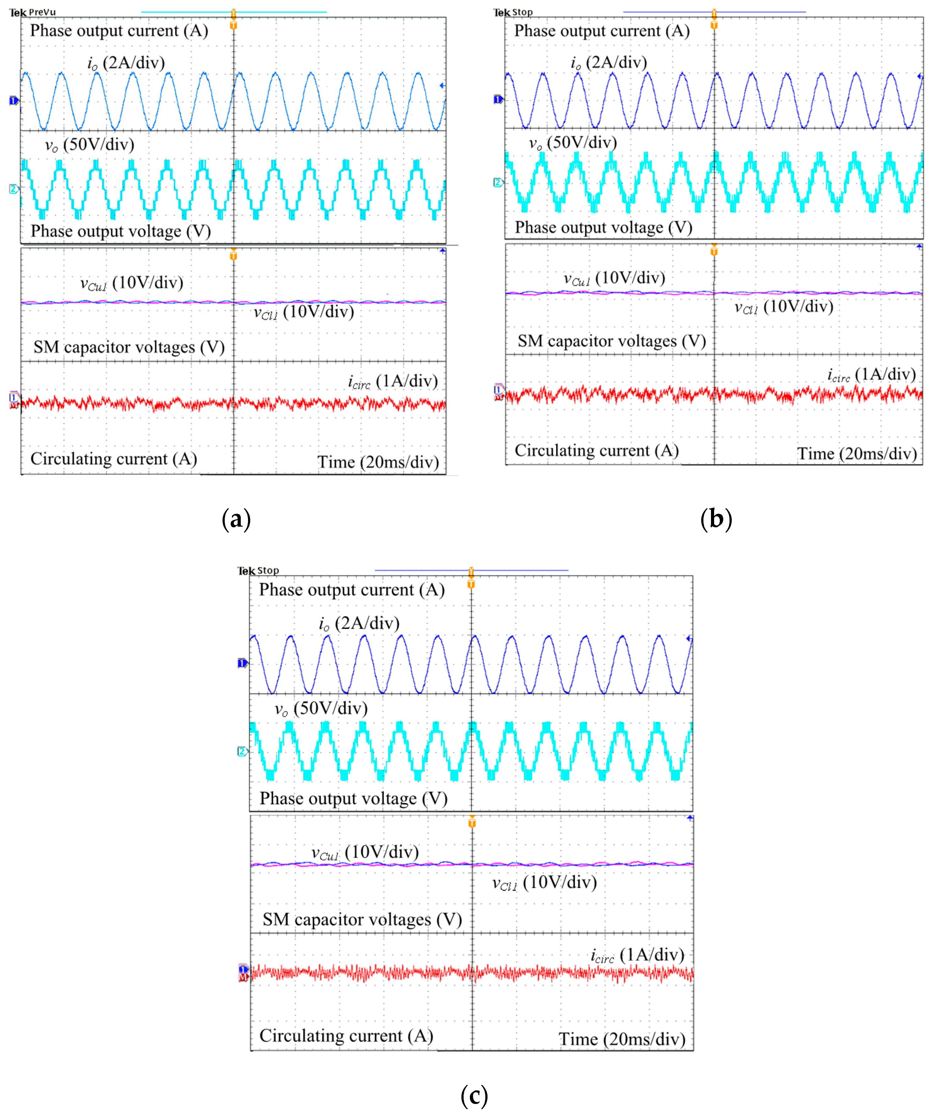
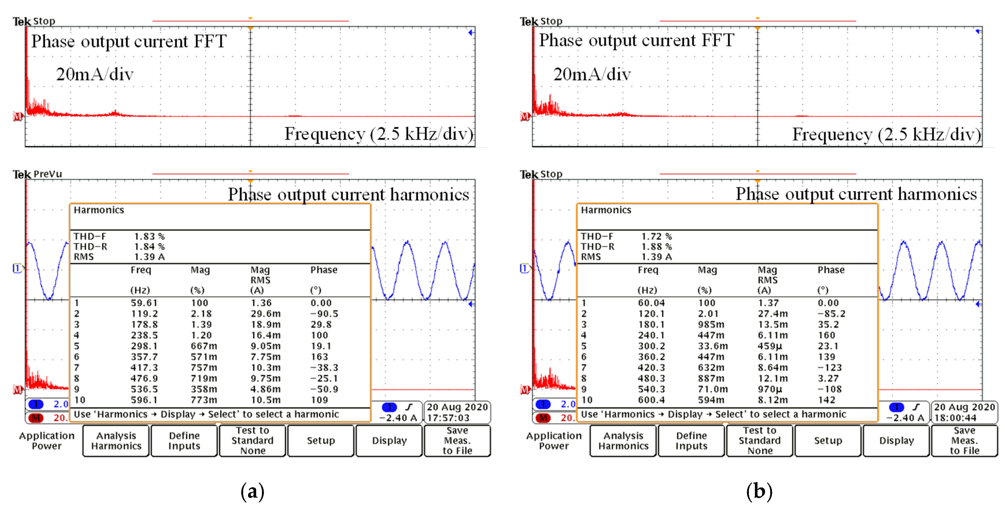
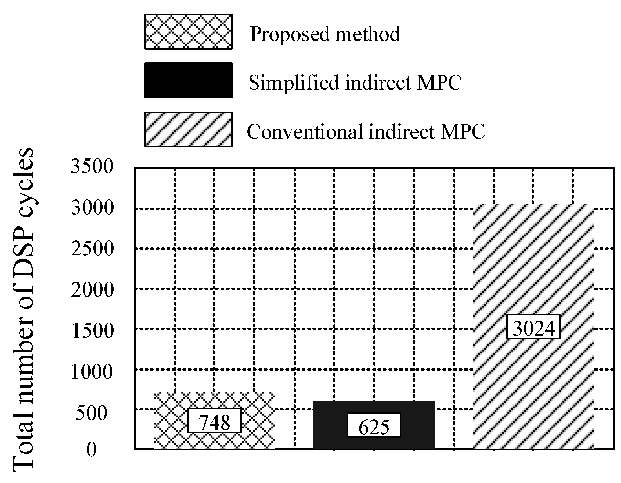
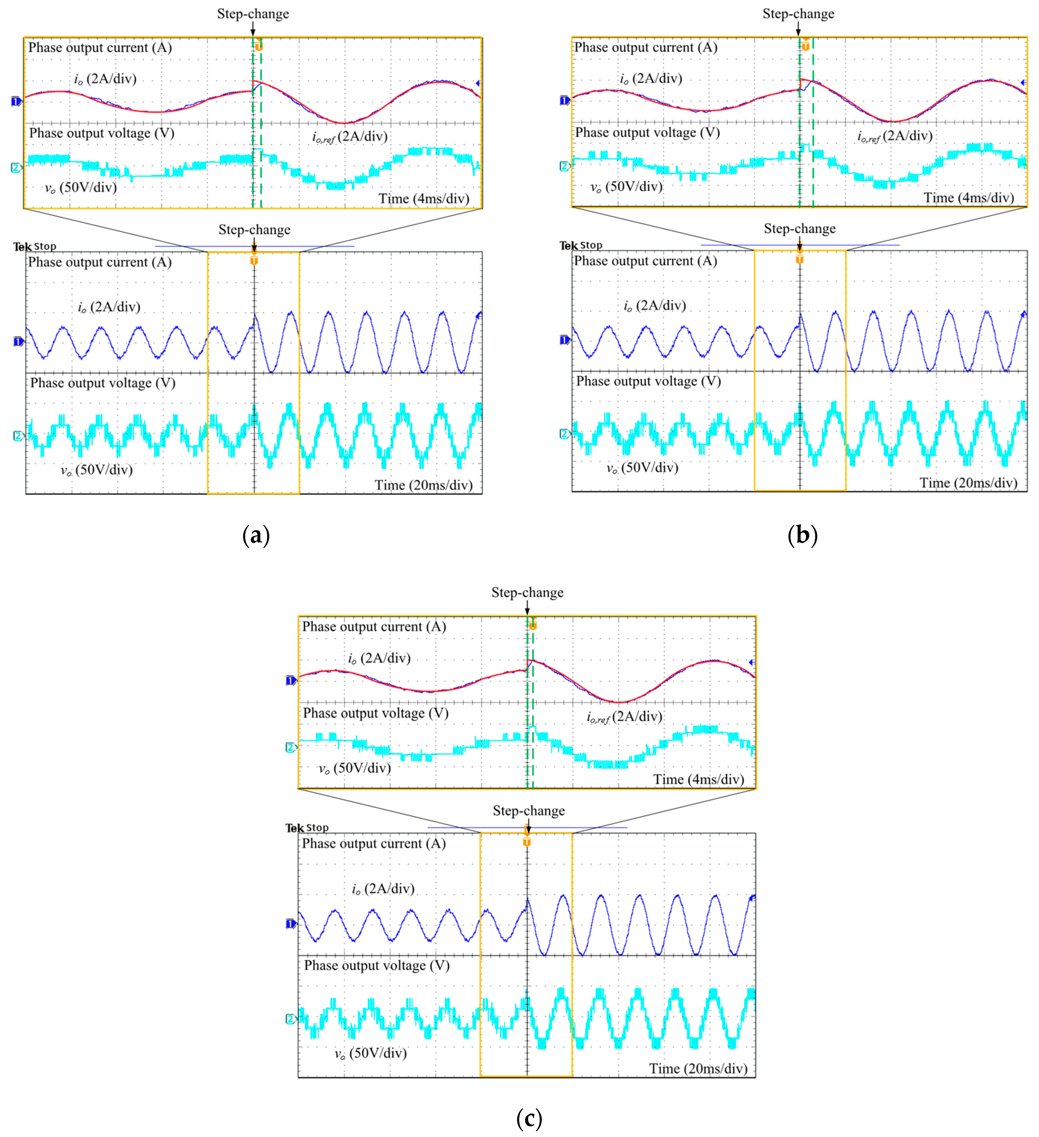
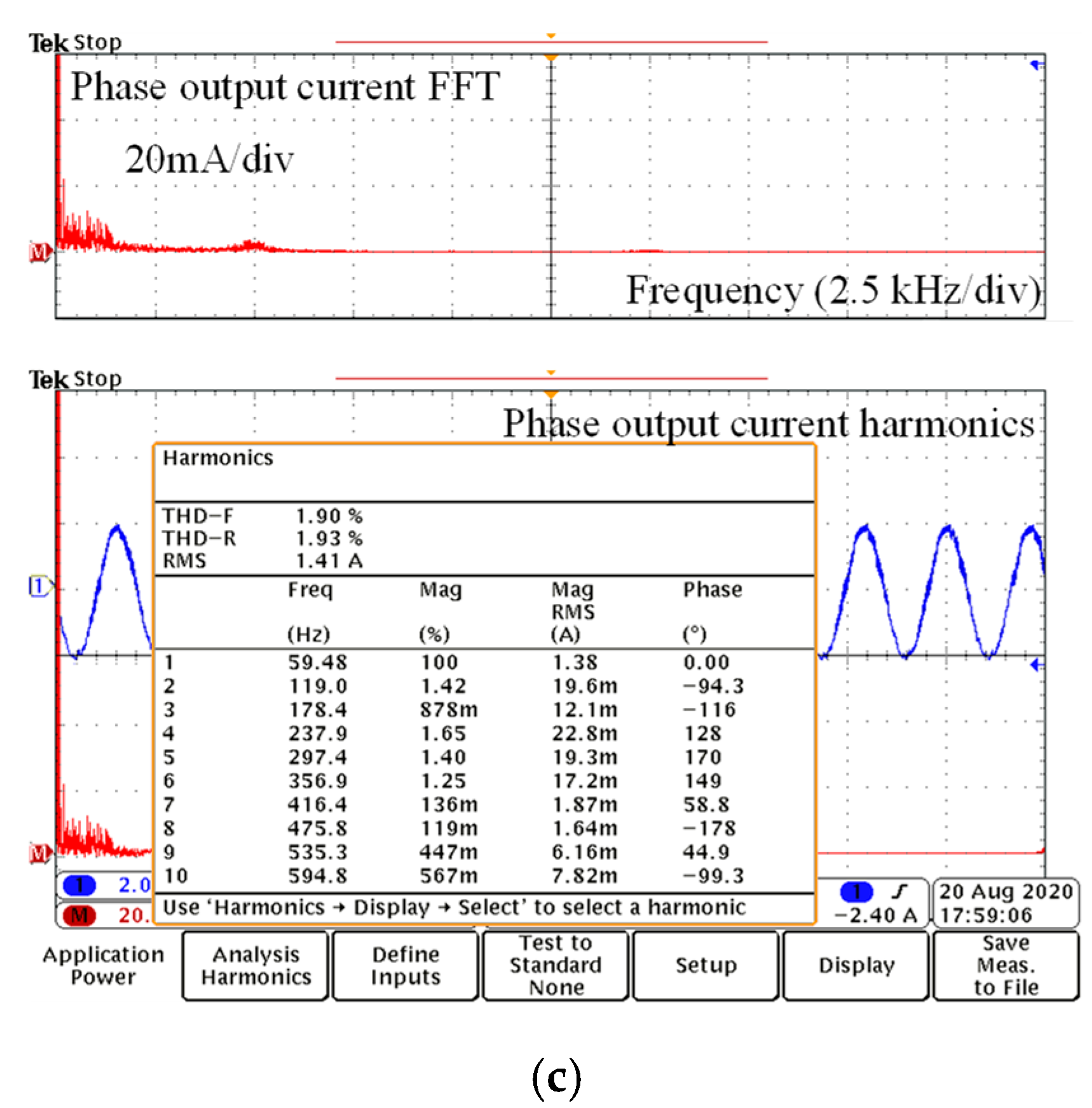
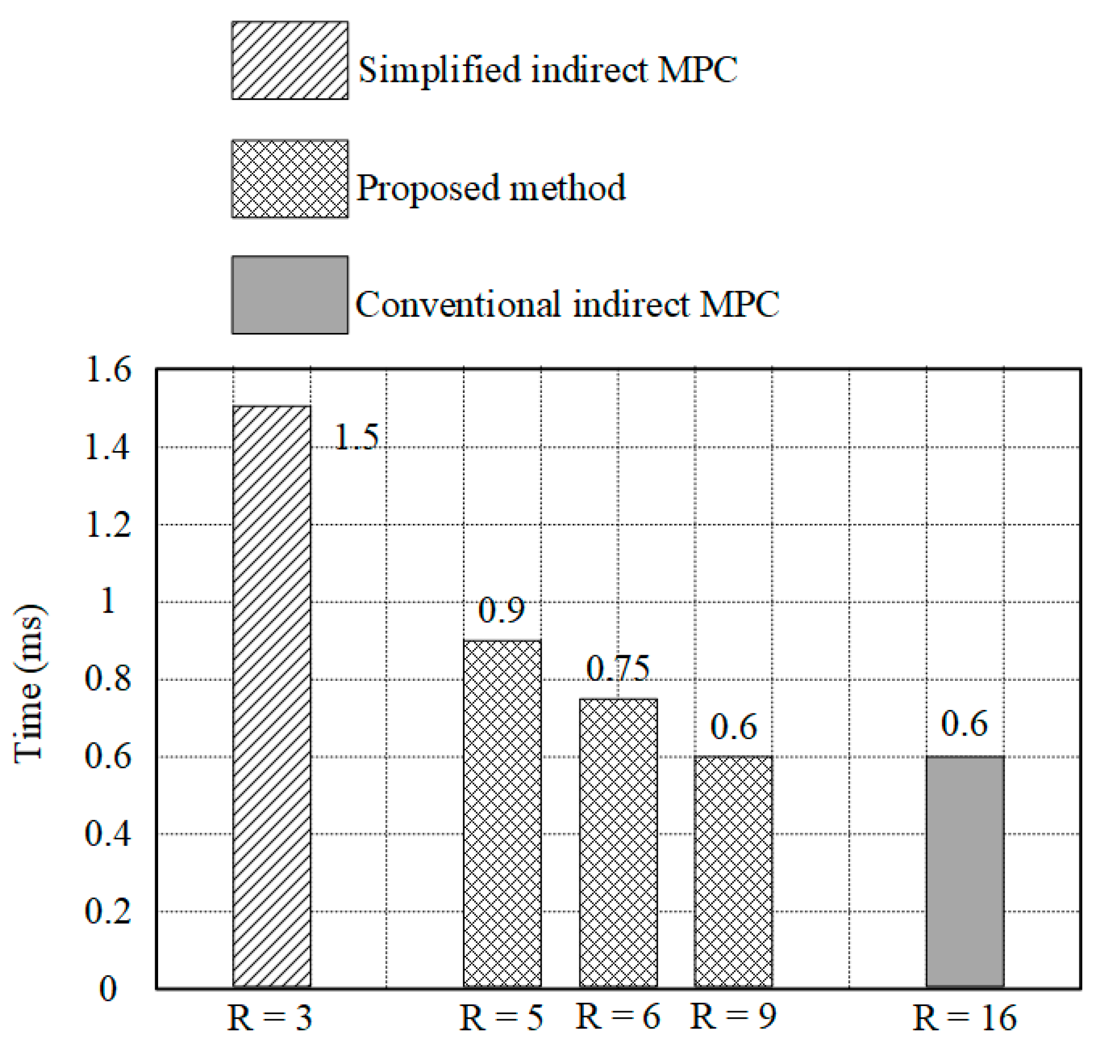
4.2. Experimental Results

Figure 11 provides the experimental outcomes of the output current, output voltage, SM capacitor voltages, and circulating current under steady-state operation. The three control schemes generate the correct sinusoidal current with accurate peak value 2 A as reference and low total harmonic distortion (THD) (1.83% for the proposed method, 1.72% for the simplified indirect MPC, and 1.9% for the conventional indirect MPC, as shown in Figure 12 and a seven-level output voltage with peak value 50 V, whereas the capacitor voltages retain a nominal value (33.33 V), and the circulating current is suppressed. The experimental results for all three control schemes show that the steady-state performance is not deteriorated, whereas the computational burden of the proposed method is significantly reduced as compared with that of the conventional indirect MPC.
The output current is in sinusoidal form can be measured using a current probe. It is connecting the current probe to the load and an oscilloscope to display the waveform of the output current. Furthermore, from (1), the output current can be calculated by the difference between the upper and lower arm currents. It should be noted that the upper and lower arm currents are mainly composed of dc, fundamental, and second-order harmonic components. Therefore, the output current exhibits the sinusoidal waveform. In terms of the circulating current, it is apparent that the circulating current contains a dc component and a second-order harmonic component. Furthermore, the circulating current exhibits a ripple and has high harmonic components due to the switching states that results in an intermediate output voltage level.
Figure 13 shows the measured DSP cycle among the three control schemes. From the experimental results, the simplified indirect MPC took the least DSP cycle (625 DSP cycles), whereas the conventional indirect MPC tool the most. The proposed method requires a higher DSP cycle compared with the simplified indirect MPC due to the step of indicating output voltage difference, but allows a considerable decrease of the DSP cycles in comparison with the conventional indirect MPC. The proposed approach reduces about 75% of the DSP cycle when compared with the conventional indirect MPC.
Figure 14 shows the magnification of the experimental results for the output current and output voltage using the three methods during the transient-state operation, where the peak value of the reference current increases abruptly from 1 A to 2 A. The output currents from all three methods track their reference currents accurately, but with different dynamic performances. As shown in Figure 14b, the simplified indirect MPC has the lowest dynamic performance among the three control schemes; this is reflected from the time when the output current changes completely. This control scheme requires approximately 1.5 ms to reach a stable state. It is apparent from Figure 14c that the conventional indirect MPC has the highest dynamic performance, where the current changes rapidly to the new reference value after only 0.6 ms, because it evaluates all possible inserted SMs, which allows this control scheme to find out the finest number of inserted SMs to follow the reference as quickly as possible. When using the proposed method, the range of the evaluation process increases from three to six choices, which shows that the proposed method requires approximately 0.75 ms to change to the new reference value. Thus, the dynamic performance of the proposed technique is better than the simplified indirect MPC method.
The time that is required to change to the new reference during the transient state is measured to analyze how the proposed method’s dynamic performance corresponds to adjusting the number of choices compared to those of the simplified indirect MPC and conventional indirect MPC. The simplified indirect MPC requires the most time, whereas the dynamic performance of the conventional indirect MPC is the highest, as shown in Figure 15. The dynamic performance of the proposed method can be improved further by increasing the number of inserted SM choices during the transient state. As Figure 15 shows, the proposed method can attain the same dynamic performance as that of the conventional indirect MPC by using all the nearest number of inserted SM choices corresponding to the previous optimal one.

5. Conclusions

The improved indirect MPC has been proposed not only to significantly lessen the computational load, but also to enhance the dynamic performance of MMCs. The proposed approach investigates the steady-state and transient state individually to determine the number of inserted SMs that should be used. During the steady-state, certain conditions were predefined to narrow the range of the number of inserted SMs, thus allowing the number of control actions and the computational burden to be reduced. Additionally, a wider range of the number of inserted SMs was considered to enhance the dynamic performance of the MMCs. Thus, unlike the conventional indirect MPC, the proposed method did not require the evaluation of all possible numbers of inserted SMs, but guaranteed a fast-dynamic performance. The steady-state and transient-state performances of the proposed method were validated experimentally. Some challenges are discussed to address in the future.
(1)
In this paper, the proposed approach has just been used in a low number of SM MMC. It is significantly demanded to make a test by applying the proposed method to the MMC systems having a considerably large number of SMs.
(2)
In addition to the simple load in the implemented experiment, applying the proposed approach to a practical load, like motor drive, should be further investigated.

Author Contributions

Data curation, M.H.N.; Formal analysis, M.H.N. and S.K.; Funding acquisition, S.K.; Methodology, M.H.N. and S.K.; Project administration, S.K.; Resources, S.K.; Software, M.H.N.; Supervision, S.K.; Validation, M.H.N.; Visualization, M.H.N.; Writing—original draft, M.H.N. All authors have read and agreed to the published version of the manuscript.

Funding

This research was supported by the National Research Foundation of Korea (NRF) grant funded by the Korean government (MSIT) (No. 2020R1A2C1013413), and funded and conducted under the Competency Development Program for Industry Specialists of the Korean Ministry of Trade, Industry and Energy (MOTIE), operated by Korea Institute for Advancement of Technology (KIAT) (No. P0012453, Next-generation Display Expert Training Project for Innovation Process and Equipment, Materials Engineers).

Conflicts of Interest

The authors declare no conflict of interest.

References

  1. Akagi, H. Classification, Terminology, and Application of the Modular Multilevel Cascade Converter (MMCC). IEEE Trans. Power Electron. 2011, 26, 3119–3130. [Google Scholar] [CrossRef]
  2. Debnath, S.; Qin, J.; Bahrani, B.; Saeedifard, M.; Barbosa, P. Operation, Control, and Applications of the Modular Multilevel Converter: A Review. IEEE Trans. Power Electron. 2015, 30, 37–53. [Google Scholar] [CrossRef]
  3. Dekka, A.; Wu, B.; Fuentes, R.L.; Perez, M.; Zargari, N.R. Evolution of Topologies, Modeling, Control Schemes, and Applications of Modular Multilevel Converters. IEEE J. Emerg. Sel. Top. Power Electron. 2017, 5, 1631–1656. [Google Scholar] [CrossRef]
  4. Hagiwara, M.; Akagi, H. Control and Experiment of Pulsewidth-Modulated Modular Multilevel Converters. IEEE Trans. Power Electron. 2009, 24, 1737–1746. [Google Scholar] [CrossRef]
  5. Vasiladiotis, M.; Cherix, N.; Rufer, A. Accurate Capacitor Voltage Ripple Estimation and Current Control Considerations for Grid-Connected Modular Multilevel Converters. IEEE Trans. Power Electron. 2014, 29, 4568–4579. [Google Scholar] [CrossRef]
  6. Li, B.; Yang, R.; Xu, D.; Wang, G.; Wang, W.; Xu, D. Analysis of the Phase-Shifted Carrier Modulation for Modular Multilevel Converters. IEEE Trans. Power Electron. 2015, 30, 297–310. [Google Scholar] [CrossRef]
  7. Deng, F.; Chen, Z. Voltage-Balancing Method for Modular Multilevel Converters under Phase-Shifted Carrier-Based Pulsewidth Modulation. IEEE Trans. Ind. Electron. 2015, 62, 4158–4169. [Google Scholar] [CrossRef]
  8. Darus, R.; Pou, J.; Konstantinou, G.; Ceballos, S.; Agelidis, V.G. Circulating current control and evaluation of carrier dispositions in modular multilevel converters. In Proceedings of the 2013 IEEE ECCE Asia Downunder, Melbourne, Australia, 3–6 June 2013; pp. 332–338. [Google Scholar]
  9. Mei, J.; Shen, K.; Xiao, B.; Tolbert, L.M.; Zheng, J. A New Selective Loop Bias Mapping Phase Disposition PWM with Dynamic Voltage Balance Capability for Modular Multilevel Converter. IEEE Trans. Ind. Electron. 2014, 61, 798–807. [Google Scholar] [CrossRef]
  10. Bocker, J.; Freudenberg, B.; The, A.; Dieckerhoff, S. Experimental Comparison of Model Predictive Control and Cascaded Control of the Modular Multilevel Converter. IEEE Trans. Power Electron. 2015, 30, 422–430. [Google Scholar] [CrossRef]
  11. Kouro, S.; Cortes, P.; Vargas, R.; Ammann, U.; Rodriguez, J. Model Predictive Control—A Simple and Powerful Method to Control Power Converters. IEEE Trans. Ind. Electron. 2009, 56, 1826–1838. [Google Scholar] [CrossRef]
  12. Perez, M.A.; Rodriguez, J.; Fuentes, E.J.; Kammerer, F. Predictive Control of AC–AC Modular Multilevel Converters. IEEE Trans. Ind. Electron. 2012, 59, 2832–2839. [Google Scholar] [CrossRef]
  13. Liu, X.; Wang, D.; Peng, Z. An improved finite control-set model predictive control for nested neutral point-clamped converters under both balanced and unbalanced grid conditions. Int. J. Electr. Power Energy Syst. 2019, 104, 910–923. [Google Scholar] [CrossRef]
  14. Lee, S.S.; Heng, Y.E. A tuning-less model predictive control for modular multilevel converter capable of unbalanced grid fault. Int. J. Electr. Power Energy Syst. 2018, 94, 213–224. [Google Scholar] [CrossRef]
  15. Li, M.; Wu, X.; Huang, S.; Liang, G. Model predictive direct power control using optimal section selection for PWM rectifier with reduced calculation burden. Int. J. Electr. Power Energy Syst. 2020, 116, 105552. [Google Scholar] [CrossRef]
  16. Vatani, M.; Bahrani, B.; Saeedifard, M.; Hovd, M. Indirect Finite Control Set Model Predictive Control of Modular Multilevel Converters. IEEE Trans. Smart Grid 2015, 6, 1520–1529. [Google Scholar] [CrossRef] [Green Version]
  17. Moon, J.-W.; Gwon, J.-S.; Park, J.-W.; Kang, D.-W.; Kim, J.-M. Model Predictive Control with a Reduced Number of Considered States in a Modular Multilevel Converter for HVDC System. IEEE Trans. Power Deliv. 2015, 30, 608–617. [Google Scholar] [CrossRef]
  18. Zhang, F.; Li, W.; Joos, G. A Voltage Level Based Model Predictive Control of Modular Multilevel Converter. IEEE Trans. Ind. Electron. 2016, 63, 5301–5312. [Google Scholar] [CrossRef]
  19. Gong, Z.; Dai, P.; Yuan, X.; Wu, X.; Guo, G. Design and Experimental Evaluation of Fast Model Predictive Control for Modular Multilevel Converters. IEEE Trans. Ind. Electron. 2016, 63, 3845–3856. [Google Scholar] [CrossRef]
  20. Gutierrez, B.; Kwak, S.-S. Modular Multilevel Converters (MMCs) Controlled by Model Predictive Control with Reduced Calculation Burden. IEEE Trans. Power Electron. 2018, 33, 9176–9187. [Google Scholar] [CrossRef]
  21. Nguyen, M.H.; Kwak, S. Simplified Indirect Model Predictive Control Method for a Modular Multilevel Converter. IEEE Access 2018, 6, 62405–62418. [Google Scholar] [CrossRef]
  22. Ramirez, D.; Zarei, M.E.; Gupta, M.; Serrano, J. Fast Model-based Predictive Control (FMPC) for grid connected Modular Multilevel Converters (MMC). Int. J. Electr. Power Energy Syst. 2020, 119, 105951. [Google Scholar] [CrossRef]
  23. Roh, C.; Kwak, S.-S. Improved Finite-Control-Set Model Predictive Control for Cascaded H-Bridge Inverters. Energies 2018, 11, 355. [Google Scholar]
  24. Harnefors, L.; Antonopoulos, A.; Norrga, S.; Angquist, L.; Nee, H.-P. Dynamic Analysis of Modular Multilevel Converters. IEEE Trans. Ind. Electron. 2013, 60, 2526–2537. [Google Scholar] [CrossRef]
  25. Konstantinou, G.S.; Ciobotaru, M.; Agelidis, V.G. Analysis of multi-carrier PWM methods for back-to-back HVDC systems based on modular multilevel converters. In Proceedings of the IECON 2011-37th Annual Conference of the IEEE Industrial Electronics Society, Melbourne, Australia, 7–10 November 2011; pp. 4391–4396. [Google Scholar]
  26. Konstantinou, G.; Pou, J.; Ceballos, S.; Picas, R.; Zaragoza, J.; Agelidis, V.G. Control of Circulating Currents in Modular Multilevel Converters Through Redundant Voltage Levels. IEEE Trans. Power Electron. 2016, 31, 7761–7769. [Google Scholar] [CrossRef]
Figure 1. Circuit topology of modular multilevel converter (MMC): (a) Structure of single-phase MMC; and, (b) Half-bridge submodule (SM).
Electronics 09 01405 g001
Figure 2. Conventional indirect model predictive control (MPC).
Electronics 09 01405 g002
Figure 3. Sorting algorithm.
Electronics 09 01405 g003
Figure 4. Block diagram of the: (a) Voltage-level-based MPC [18]; (b) fast MPC method (FMPC) [19]; (c) preselection and Simplified MPC [20,21].
Electronics 09 01405 g004
Figure 5. Block diagram of the proposed indirect MPC.
Electronics 09 01405 g005
Figure 6. The possible number of inserted SMs under different conditions: (a) All possible number of inserted SMs; (b) Possible number of inserted SMs among N − 1, N, and N + 1; (c) Possible number of inserted SMs corresponding to level condition; and, (d) Possible number of inserted SMs corresponding to circulating current condition.
Electronics 09 01405 g006
Figure 7. Flowchart of the proposed method in steady-state with N = 3.
Electronics 09 01405 g007
Figure 8. Different possible number of inserted SMs in transient state: (a) Possible number of inserted SMs corresponding to circulating current condition; (b) possible number of inserted SMs without circulating current condition; (c) possible number of inserted SMs without level condition; and, (d) possible number of inserted SMs corresponding to nearest number of inserted SMs.
Electronics 09 01405 g008aElectronics 09 01405 g008b
Figure 9. Magnified simulation results acquired by the seven-level MMC (N = 3) during the transient state of reference current changes by using the improved dynamic performance control.
Electronics 09 01405 g009
Figure 10. Setup diagram and photograph of experimental arrangement: (a) circuit diagram; (b) single-phase seven-level MMC prototype; and, (c) digital control system used in the experiment.
Electronics 09 01405 g010aElectronics 09 01405 g010b
Figure 11. Experimental results acquired by the seven-level MMC (N = 3) during steady-state by employing: (a) the proposed method; (b) the simplified indirect MPC; and, (c) the conventional indirect MPC.
Electronics 09 01405 g011
Figure 12. Frequency spectrum of phase output current by employing: (a) the proposed method; (b) the simplified indirect MPC; and, (c) the conventional indirect MPC.
Electronics 09 01405 g012aElectronics 09 01405 g012b
Figure 13. Number of digital signal processor (DSP) cycles comparison among three control schemes at N = 3.
Electronics 09 01405 g013
Figure 14. Magnified experimental results acquired by the seven-level MMC (N = 3) during transient state by employing: (a) the proposed method; (b) the simplified indirect MPC; and, (c) the conventional indirect MPC.
Electronics 09 01405 g014
Figure 15. Comparative time in the transient state with R is the range of the possible number of inserted SMs.
Electronics 09 01405 g015
Table 1. Comparison of previous approaches regarding a large number of SMs.
MethodsIdea to Reduce Computational BurdenRequirementsCapability of Controlling Circulating CurrentReduction of Computational Burden
Conventional indirect MPC [16]Decouple the voltage balancing task from the cost functionNo strict requirementsGoodStill high
Voltage-level-based MPC [18]Tolerance band around average capacitor voltageConsidering the tolerance band valueGoodGood
FMPC [19]Considering neighboring output voltage levelExact look-up tableNot mentionedNo discussion
Preselection MPC [20]Considering neighboring output voltage levelConsidering the circulating current controllability with large number of SMsGoodGood
Simplified indirect MPC [21]Considering neighboring output voltage level and circulating current conditionConsidering the circulating current controllability with large number of SMsGoodGood
Table 2. Comparison among proposed method and previous approaches regarding the number of control actions in single-phase MMC with N = 3.
No. of SMs N = 3Steady-StateTransient State
No. of control actionDirect MPC [10]6464
Indirect MPC [16]1616
Simplified indirect MPC [21]33
Proposed method35,6 or 9
Table 3. Experimental parameters.
DC-link voltage Vdc(V)100
Number of SMs per arm N3
Nominal voltage VC (V)33.33
SM capacitance C (mF)2.2
Arm inductance La (mH)3
Load inductance L (mH)10
Load resistance R (Ω)20
Output frequency fo (Hz)60
Sampling frequency fsp(kHz)10
Rated MMC kVA S (kVA)0.1

