Review

Recent Developments and State of the Art in Flexible and Conformal Reconfigurable Antennas

1
School of Engineering, Macquarie University, Sydney, NSW 2109, Australia
2
School of Electrical and Data Engineering, University of Technology Sydney, Sydney, NSW 2007, Australia
*
Author to whom correspondence should be addressed.
Electronics 2020, 9(9), 1375; https://doi.org/10.3390/electronics9091375
Submission received: 14 July 2020 / Revised: 20 August 2020 / Accepted: 21 August 2020 / Published: 25 August 2020
(This article belongs to the Special Issue Reconfigurable Antennas)

Abstract

:
Reconfigurable antennas have gained tremendous interest owing to their multifunctional capabilities while adhering to minimalistic space requirements in ever-shrinking electronics platforms and devices. A stark increase in demand for flexible and conformal antennas in modern and emerging unobtrusive and space-limited electronic systems has led to the development of the flexible and conformal reconfigurable antennas era. Flexible and conformal antennas rely on non-conventional materials and realization approaches, and thus, despite the mature knowledge available for rigid reconfigurable antennas, conventional reconfigurable techniques are not translated to a flexible domain in a straight forward manner. There are notable challenges associated with integration of reconfiguration elements such as switches, mechanical stability of the overall reconfigurable antenna, and the electronic robustness of the resulting devices when exposed to folding of sustained bending operations. This paper reviews various approaches demonstrated thus far, to realize flexible reconfigurable antennas, categorizing them on the basis of reconfiguration attributes, i.e., frequency, pattern, polarization, or a combination of these characteristics. The challenges associated with development and characterization of flexible and conformal reconfigurable antennas, the strengths and limitations of available methods are reviewed considering the progress in recent years, and open challenges for the future research are identified.

1. Introduction

Reconfigurable antennas have received a lot of attention in modern communication systems due to their versatile applications by offering extra functionality. A reconfigurable antenna is defined as a single structure that is capable of switching between one and a combination of characteristics such as frequency, pattern, and polarization [1]. These structures with their flexible and multi-operation characteristics offer compact and cost-effective antennas for modern communication systems such as cellular radio systems, satellite communication, airplane, health care systems, and unmanned airborne vehicle (UAV) systems [2,3,4]. There has been extensive research and substantial advancements demonstrated in the various types of reconfigurable antennas made from rigid and conventional materials in the last few decades. New and modern communication systems’ are moving toward wearable technology and system [5]. Wearable technology and systems include flexible electronics and displays, conformal consumer electronic gadgets and devices for body area networks (BANs) [6,7,8]. The requirements for flexible and reconfigurable antennas as a key component of the wearable systems have been increased because wearable devices must cope with the dynamics of the various surfaces.
Antenna reconfigurability is achieved by changing the antenna’s current path, physical structure, or electrical properties. As Figure 1 shows, there are various methods to achieve reconfigurability in the four main categories. The progress in the development and realization of the flexible reconfigurable antennas was not as fast as their rigid counterparts. There are various existing challenges for the realization of these types of antennas. Figure 1 presents the existing reconfiguration techniques, which include: the PIN diode, the microelectromechanical systems (MEMS) switch, the varactor from the electrical category, the microfluidic-based method and the origami-based antenna. The photoconductive switch is made of semiconductor materials and uses bias lines instead of metallic wires [9]. The reason for not having a flexible reconfigurable structure with this switch is because of the challenges of integrating it with unconventional and flexible materials. Moreover, the limited range of flexible materials and permittivity restricts researchers in this area in employing reconfiguration techniques based on smart materials. These are based on reconfiguring the substrate of the antenna through changing its permittivity or permeability under different levels of voltage [10].
A comprehensive review papers focusing exclusively on simulation [11], a specific reconfigurability method [10,12], antenna types [2,13], and other [14,15,16] of rigid antennas have been presented. Despite great efforts for comprehensive reviews of rigid antennas, there are no comprehensive review papers for the flexible reconfigurable antennas. In this review paper, we summarize recent developments in flexible pattern, frequency, and polarization reconfigurable antennas, as well as antennas with two feature reconfigurability. The purpose of this paper is to review the reconfiguration techniques, the challenges and limitations for design and fabrication, the achieved results and a comparison of the materials used in flexible and rigid structures. This leads to the recognizing of the current gap in this field and identifying of the possible future work in this area.
In the following sections, we discuss reconfigurable antennas in different categories:
  • Frequency-reconfigurable antenna;
  • Pattern-reconfigurable antenna;
  • Polarization-reconfigurable antenna;
  • Multiple reconfigurable features in an antenna.

2. Frequency-Reconfigurable Antennas

Frequency reconfigurable antennas have attracted researcher and industry communities’ attention due to its capability to reduce the size of the front end systems and minimize interference with other wireless systems and maximize throughput [1]. The resonance of a proposed flexible antenna can be switched through the change of the effective length of radiator and the modification in the ground plane and feeding networks with the help of an electrical switch [17,18,19,20,21,22,23,24,25], by microfluidic-based antenna [26,27] and the use of a conductive fluid as a switch for a main radiating element [27], changing the antenna’s permittivity [28,29] or the antenna’s shape or type [30,31,32,33,34,35,36,37,38,39,40,41,42,43,44,45,46,47,48,49,50,51,52,53].

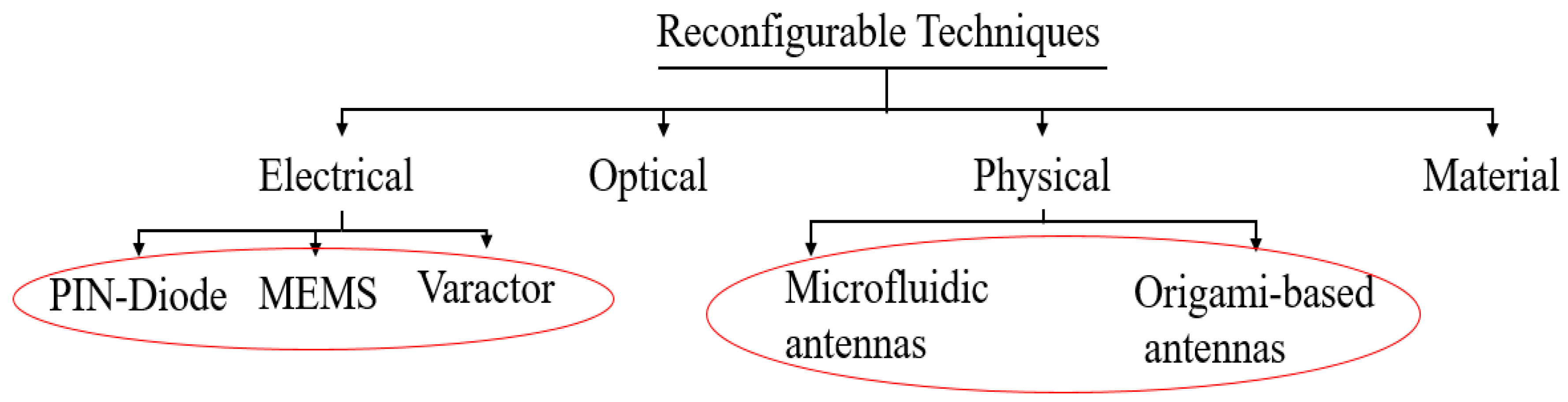
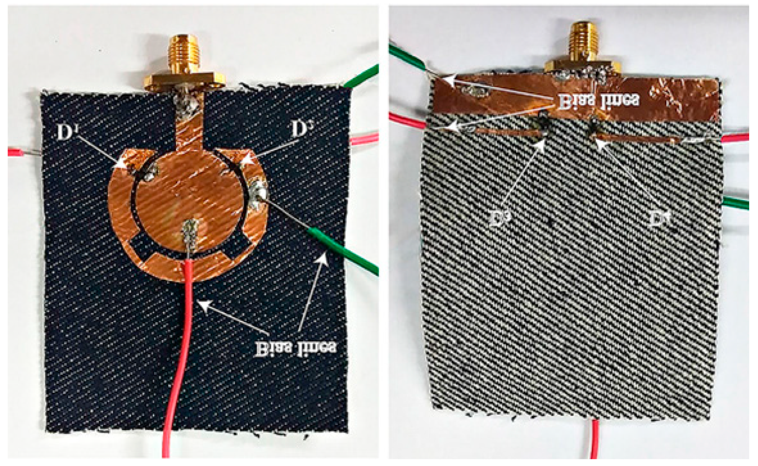
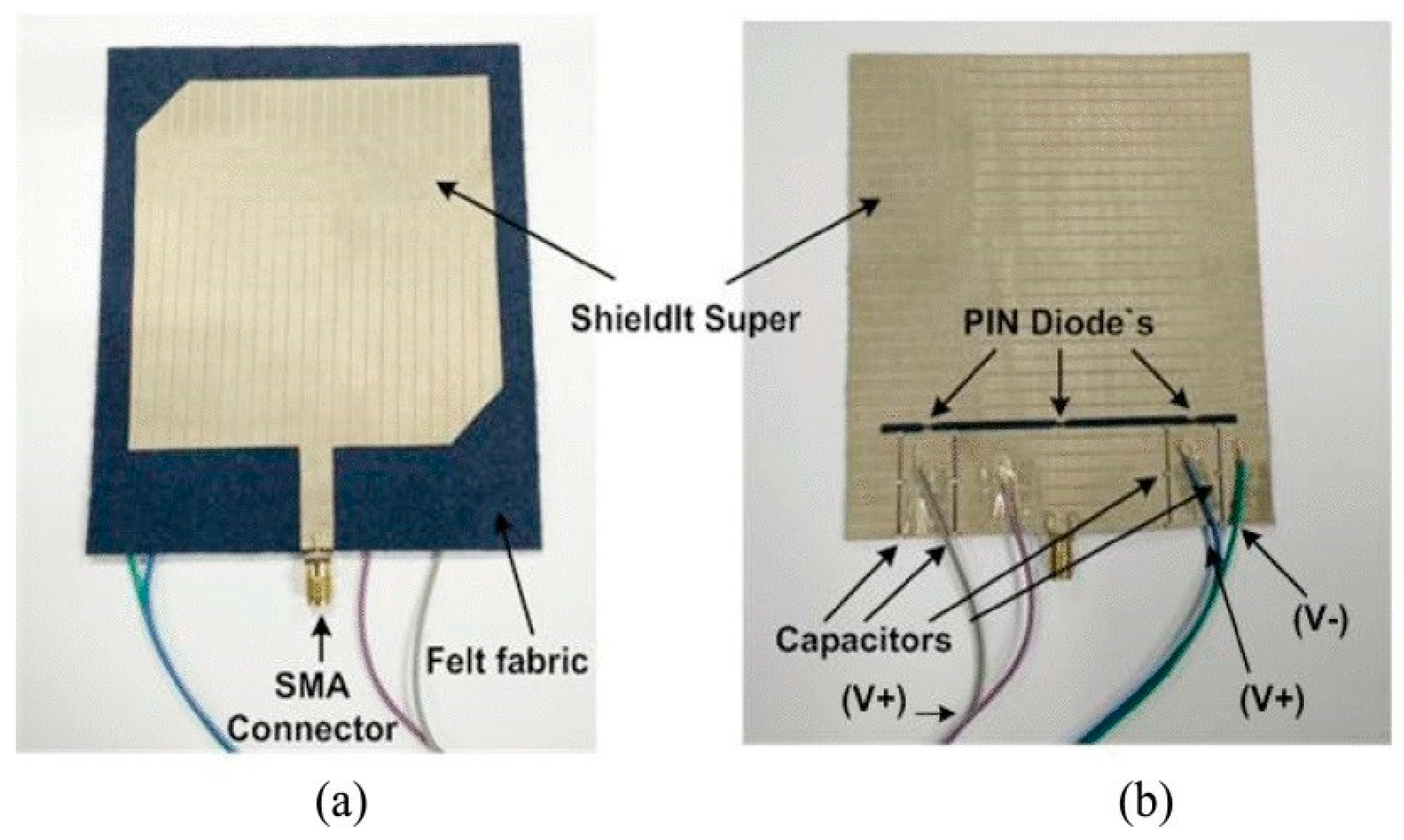
2.1. Antennas Based on Electrical Switches

Electrical switches are employed for the interconnecting of adjacent elements of the antenna patches [18,19,20,21] or varying the length of the slots on the patch or ground plane [1,22], modification on feeding networks [23] or switching between feeding ports [17] in order to realize frequency reconfigurability. Reconfigurability is limited to specific frequencies by employing a pin diode and MEMS switch, whereas continuous ranges of frequency reconfigurability are obtained by using varactor diodes.
In some research, the frequency reconfigurable antennas performance is analyzed through simulation [19,23] or it is verified through fabrication of prototypes that employ a 1 mm stub as an ideal diode. This is due to the challenges in the realization of the antenna with electrical switches such as placing diodes on unconventional materials, the need for a large RF bias network, and the effects of the nonlinearity of diodes and harmonics parameters. In other research, the conductive parts of the antenna where the diodes are placed are made of conventional materials to make the integration process easier [20,22,54].
In Reference [18], the microstrip patch antenna is placed on the Indigo blue jeans. A diode placed between two rectangles on the patch creates the reconfigurability between 2.4 GHz and 2.5 GHz for Bluetooth and WiMAX applications. In other research [23], two diodes are placed across a T-slot developed on the feed line of the rectangular patch antenna to reconfigure its frequency bands between 1.8 GHz, 2.3 GHz, and 2.4 GHz. In simulation analysis, Shieldlt Super is employed for the antenna conductive parts and it is placed on a Felt substrate with ε r = 1.44. In Reference [19], dual-band reconfigurability is achieved through the connection of the two rectangular patches by eleven switches. An antenna is placed on the denim jeans textile and reconfiguring, between its two frequency bands 2.44 GHz (Wi-Fi) and 3.54 GHz (WiMAX).
Further investigation has been done by fabricating designed flexible reconfigurable antennas, employing DC circuits, and the measurement. The diodes are placed on the antenna, and in some cases, DC circuits are integrated as well. In Reference [20], the proposed textile antenna reconfigures between 2.45 GHz and 5 GHz. The copper tape is used for the patch and ground plane, and a denim material is used for the substrate. The diode is integrated on the copper tapes and connects two adjacent patches to create these two frequency bands. For the proposed antenna, the DC is connected to the antenna by means of two wires. In Reference [22], the proposed antenna is placed on a flexible polyethylene terephthalate which reconfigures between two states: a single band structure at 2.42 GHz and dual-band with different polarizations at 2.36 GHz and 3.64 GHz. The structure is composed of a folded slot and the radiation characteristics of the stub is altered by a PIN diode placed on the stub. The antenna is fabricated with inkjet-printing technology. Further study has been done on this antenna in [54]. An artificial magnetic conductor (AMC) surface is added to this structure in order to improve its radiation performance and to reduce the specific absorption rate (SAR). The performance of both antennas has been measured for the flat and curved positions. To control the diodes, DC voltage is applied with the RF signal through the input connector to eliminate the need of complex DC biasing circuit, thus preserving the antennas flexibility.
The same approach for biasing of the diode is employed in [24], but more challenges arise in the design process when unconventional materials are employed for the conductor and ground plane of the antenna.
The proposed antenna in [24] is fabricated by embedding conductive fabric into the flexible polydimethylsiloxane (PDMS) polymer [55,56,57] and all the active and passive elements of the antenna are fully encapsulated in the structure (Figure 2). To realize the antenna reconfigurability, two varactors are placed between a rectangular patch and a parasitic patch (made of conductive fabric) and are biased with same DC voltage. The frequency resonance is tuned continuously between 2.3 GHz and 2.65 GHz. The antenna in [21] consists of a rectangular-grounded loop which is excited by a monopole antenna fed by a coplanar waveguide. A U-shaped slot is loaded to the monopole to achieve dual-band operation. This dual polarized antenna operates within 2.21 GHz to 2.69 GHz and 3.14 GHz to 3.55 GHz bands. The resonance of the higher band is tuned by switches placed within the U-slot.
Another approach for designing a reconfigurable antenna is by switching between two modes of the antenna through two-port excitation [17]. The proposed graphene conductive ink printed textile-based microstrip antenna in [17] can switch between 3.03 GHz and 5.17 GHz. The frequency reconfigurability is achieved by exciting the two modes of TM02 and TM20 through two-port excitation. A challenge of the switching between these two ports is addressed by introducing a single pole single throw switch to the structure.
DC circuits are integrated in different parts of antenna such as ground plane [1,58] or within the structure. In References [25,59], DC control circuits are integrated within commercial snap-on buttons. The snap-on reconfigurable wearable antennas are proposed to address the challenge of connection between rigid components to textile materials. This dual-band reconfigurable textile patch antenna is fabricated and the measurement results are reported showing a tuning range of 32.8% and 8.8% at 2.45 GHz and 5.8 GHz ISM bands, respectively [25].
The methods discussed so far have all been based on pin diodes and varactors. RF MEMS switches are also widely employed by researchers for realization of reconfigurability due to their low loss and distortion, small size, and high isolation [60]. The MEMS switch geometry and materials can be tailored to meet a specific size requirement and the desired actuation voltage, respectively [60,61]. While in most published literature, MEMS switches are integrated on the rigid substrate and one switch topology is used, great effort in integrating MEMS switches on flexible substrate is demonstrated in [62]. A multiband Sierpinski fractal antenna is proposed in [60], which is realized on a liquid crystal polymer (LCP) substrate, with three sets of used RF MEMS switches. Each switch has a different actuation voltage. The antenna operates at four frequencies between 2.4 GHz and 18 GHz without the need of extra lines to bias the switches.
As shown above, the main challenges for realizing frequency reconfigurable antennas with the electrical switches are based on the need for a DC-bias, and the adverse effects of rigid components on the antenna’s flexibility. Moreover, in reconfigurable antennas based on electrical switches, antenna performance is degraded. The harmonics and intermodulation distortion is generated because of diode nonlinearities and gain compression.

2.2. Mechanically Frequency-Reconfigurable Antennas

Aside from the aforementioned challenges, the mechanical stability and rigidity of the frequency reconfigurable antennas based on electrical switches (PIN diodes and varactors) are not sufficient for some applications such as wearable antenna for gadget [63]. The high strength fields in MEMS switches limit the antennas with this type of switch to low-power applications [27]. To overcome these issues, the new categories of stretchable antennas such as microfluidic antennas, antennas based on micromesh structures, and origami-based antennas have been introduced. In the following sections, different categories of the mechanical frequency reconfigurable antennas with their existing challenges are presented.

2.2.1. Microfluidic Antennas

Recent development in the composite structure manufacturing creates the ability to embed microvascular networks in flexible materials and enables conductive or dielectric fluid to be injected into these materials. To reconfigure the antenna’s frequency, the conductive fluid is used as a switch [27], the reactive loading effects of the fluid metal are used in [64,65], antenna fabricated by injecting alloys is elongated via stretching [66,67], the permittivity range of substrate is changed [28,29].
In microfluidic antennas in which conductive fluid is used as a switch, PDMS and styrene ethylene butylene styrene (SEBS) are usually used to produce microfluidic channels. The examples of liquid metals are mercury and eutectic gallium indium alloy (EGaIn). There is no need for electrical actuation switches in these types of the antenna which leads to enable efficient power handling. In the first microfluidic reconfigurable antennas with simple geometry, the liquid metal conductor is used in the PDMS channel [26]. In the presented frequency reconfigurable dipole antenna, for the microfluidic channels, SEBS with the ε r = 2.3 and loss of 0.07 is employed and the channels are filled with EGaIn. The proposed antenna reconfigures from 2 GHz to 5.5 GHz by increasing strain up to 120% [68]. In Reference [27], the liquid metal is employed as a shortening switch. The frequency of the proposed antenna shifts between 4.6 GHz, 3.84 GHz and 5.34 GHz by emptying and filling the liquid metal to the microchannel to the lengths of λ/2 and 4λ. The antenna is placed on an S-glass composite substrate with ε r = 3.4 at 4.6 GHz. A copper-tape and an EGaIn is used for the ground plane and the fluidic conductor, respectively.
In other research, the reactive loading effect of the fluid metal is used for tuning of a coplanar waveguide (CPW) folded slot antenna and miniaturization as well [64,65]. Two pairs of microfluidic channels are used as a switch to reconfigure between 2.4 GHz, 3.5 GHz, and 5.8 GHz [64]. The antenna is placed on Taconic TLY substrate with ε r = 2.2, tan δ = 0.0009, with a thickness of 1.53 mm and two separate PDMS structures are used for two channels. The same approach is employed in [65], where liquid metal is also used as a reactive load on top of the antenna to achieve tuning and miniaturization as well.
In other types of microfluidic antennas, the frequency is tuned mechanically by elongating the antenna via stretching [66,67]. In Reference [66], a dipole antenna is fabricated by injecting EGaIn into microfluidic channels placed in PDMS substrate. The antenna frequency is tuned from 1850 MHz in a relaxed position (54 mm length) to 1600 MHz in the elongated position (66 mm length). In Reference [67], a stretchable frequency reconfigurable antenna is fabricated by injecting liquid metal alloy into a flexible substrate. Galinstan and silicone TC5005 are used for alloy and substrate, respectively. Instead of a microchannel, a square reservoir is fabricated in the flexible substrate. The frequency of the antenna is tuned from 1.3 GHz to 3 GHz by stretching up to 300% and varying the electrical length of the patch from 31 mm to 87 mm.
Despite the presented works [26,27,64,65,66,67] in which conductive fluid is used for radiating element, in [28,29], a microchannel is employed for adding different dielectric liquid materials to the antenna. The frequency shift is achieved in [28,29], by changing the permittivity range by inserting different fluids (air, acetone, and de-ionized (DI) water) into the existing channels.
As mentioned previously, fluidic-based antennas resist various or long time deformation compared to conventional antennas. In addition, the higher conductivity of conductive liquid compared to conductive fabrics, makes the design of an antenna with higher efficiency possible. On the other hand, there is a limitation for realizing the complex patterns for patch with this method. For antennas in which reconfigurability is achieved by changing the permittivity, the limited range of liquid dielectric, does not allow the researcher to have a wide range of reconfigurable antennas and frequency bands. Moreover, their ability for stretching up is only in one direction for complex geometries, or in some cases the accurate mechanically control of antenna is difficult [69].

2.2.2. Antennas Based on Metallic Micromesh

In Reference [63], a semitransparent and flexible antenna which consists of a series of tortuous micromesh structures is presented. The proposed antenna can be stretched up to 40% without any problem. The mesh parts are made of copper and are placed on PDMS. The antenna’s frequency reconfigures from 2.94 GHz to 2.46 GHz by increasing the tensile strain through mechanically elongating the meandering line of the antenna.

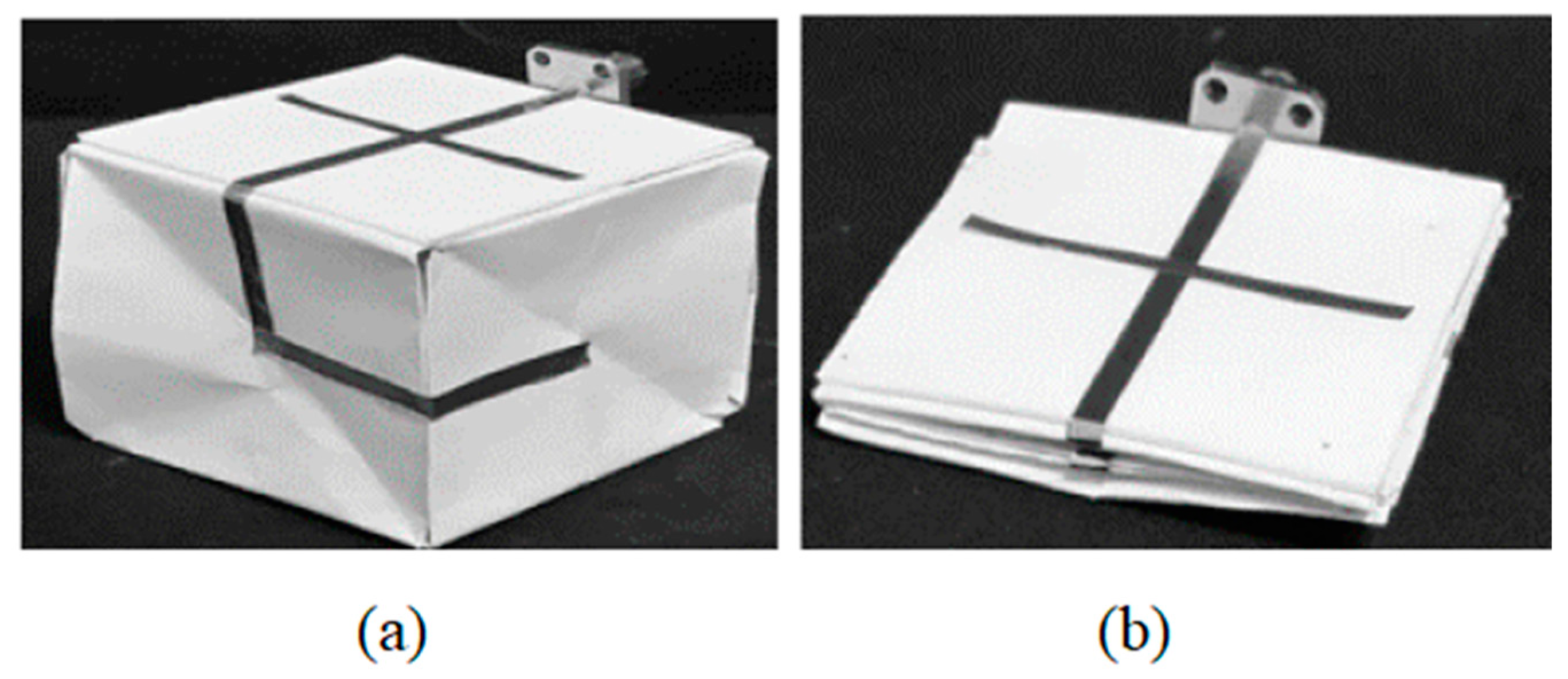
2.2.3. Kirigami and Origami-Based Antennas

In the class of mechanically reconfigurable structures, Kirigami and Origami-based antennas demonstrate RF characteristics that can be self-tuned by shape reconfiguration.
These antennas with their unique features are able to change the shapes and sizes of the 3-D structures or transform 2-D shapes into other 2-D and 3-D shapes by employing flexible materials [70,71]. This leads to the changing of the effective lengths [30], size [31] and type of antenna [32,33]. Various types of frequency reconfigurable origami-based antennas such as helix antennas [31,34,35], microstrip [32], yagi [36], dipole [37,38,39] and monopole [40] antennas have been presented in the literature.
In most of the existing 3-D origami helical antenna [41,42,43,44,45,46,47,48,49], accordion antenna [51], and spring structure [50], the frequency reconfigurability is achieved by changing the antenna’s height. In [49], the proposed helical antenna is fabricated by copper foil on a paper, which switches between 1.82 and 2.14 GHz in folded state (H = 38 mm), and 860 MHz in the unfolded state (H = 255 mm). The same approach is presented in [43], in which origami quadrifilar helical antenna reconfigures between the normal mode at frequencies of 0.83 GHz, 1.17 GHz, or 1.5 GHz with H = 371 mm and axial mode at frequency of 1.23 GHz with circular polarization with H = 200 mm. In Reference [31], the frequency is tuned in the 3-D origami bifilar helical antenna by applying a force at its top and controlling its height. The antenna is made of copper tape on a sketching paper substrate with ε r = 3.2. The frequency can be reconfigured among seven frequencies from 0.86 GHz to 3 GHz for three heights of 273 mm, 154 mm, and 25 mm. Another origami quadrifilar helical antenna is presented in [44]. The resonance frequency is tuned between 2.07 GHz, 3 GHz and 4.45 GHz by varying the height of antenna to 120 mm, 75 mm and 105 mm. Unlike the previously presented origami helical antenna, an origami reflector is used around this antenna to enhance its gain. This design is modified and an origami reconfigurable quadrifilar helical with circular polarization for higher frequency bands is presented [72]. The proposed antenna reconfigures between K, Ka, and extremely high-frequency bands by varying the height of antenna to 364 mm, 345 mm and 181 mm, respectively. Beside the helical origami structures, in spring antenna, the frequency can be tuned by changing the height of structure. In Reference [50], a tunable origami spring antenna with continuous frequency shifting from 1.1 GHz to 1.4 GHz is presented. The antenna is folded and unfolded with the help of an actuation system to the various heights from 60 mm to 145 mm. The actuation system is also employed in multi-radii monofilar helical antenna [73]. The antenna reconfigures between three bands of 1.22–1.84 GHz and 1.78–3.54 GHz and 3.64–4.04 GHz, with circular polarization. The antenna consists of a combination of two helical antennas with different radii and is fabricated from Kapton and copper trace.
Frequency reconfigurability based on converting 2D structure into 3D shape is presented in [30,32,37]. In References [30,37], reconfigurable origami-based dipole antennas with mechanically robust and durable structures have been introduced. In Reference [37], an E-textile accordion-dipole is fabricated on an Organza fabric. The frequency is reconfigured from 760 MHz to 1015 MHz range through changing the effective lengths by placing the antenna on a series of four Styrofoam fixtures which provide the changing angles of inclination from 0 to 60 degrees. A self-folding origami antenna that converts 2D structure into 3D shape is proposed in [32]. The antenna is a polystyrene subassembly that reconfigures between a microstrip patch antennas with a bandwidth of 1.5 GHz to 3.5 GHz to a monopole antenna with a bandwidth of 2.0 GHz to 2.3 GHz. The reconfigurability is realized by the concept of light activation and the bending of the polymer sheet assembly toward the light and away from the second port of the microstrip transmission line. The antenna is fabricated using RT/duroid 5870 with ε r = 2.33.
The transformation from a planar structure to a 3-D structures for frequency reconfigurability is employed in [33,38,40,74]. A frequency switchable monopole antenna which is designed on an origami magic cube is proposed in [40]. The antenna reconfigures between 850 MHz to 1000 MHz and 1.3 GHz to 1.6 GHz for the unfolded and folded states due to the change in the length of the antenna. The same approach is used in [74] to design a dual-band antenna operating at 1.57 GHz and 2.4 GHz in the folded state and 900 MHz and 2.3 GHz in the unfolded state. The proposed antenna consists of a meandered monopole that is loaded by a microstrip open-ended stub. The open-ended stub controls the second resonance of antenna by changing its length (Figure 3). In Reference [38], a frequency-reconfigurable dipole antenna using an origami flasher is proposed. In this structure, the dipole length is increased in the folded state into a cube. The antenna frequency is switched between 750–800 MHz (folded) and 1.19–1.26 GHz (unfolded). The transformation from a dipole structure to a 3D conical spiral structure is made in a proposed morphing Nojima origami antenna in [33]. The antenna operates at 0.48 GHz and 2.5 GHz in unfolded (dipole antenna) and fully folded state (conical spiral antenna), respectively.
Most origami-based antennas are designed using paper which creates poor durability and performance stability [75]. Moreover, to accurately control the change in the antenna dimensions and shape is not easy due to the high flexibility nature of paper. This also limits the range of the frequency reconfiguration to a couple of points. Therefore, in [75], a dipole antenna based on multi-material 3D printing technology is proposed, which can provide a continuous frequency reconfigurability from 0.95 GHz to 1.6 GHz through a precise structure manipulation by a robot.
In Reference [76] a frequency reconfigurable monopole antenna based on kirigami technique is presented. A three-story tower kirigami is used for this antenna. This technique provides a more stable structure compared to a free-standing structure, as well as a volume reduction. In this antenna, a horizontal monopole antenna is designed on a two dimensional flat PET film with a frequency of 0.42 GHz, which can be stretched to the three-storey tower to operate at a frequency of 0.53 GHz.
Most of the origami-based antennas use paper in their structure due to its high foldability, high thermal stability and lightweight. Despite the advantages of using paper in origami antennas, the roughness on the surface of paper creates some electrical properties of the conductive patterns. This can be addressed by coating the paper with polymers, but the folding of antenna will be affected. Therefore, in [77], a nonopaper approach with higher transparency and a smoother surface is presented for a foldable frequency reconfigurable antenna. The frequency of V-shaped silver nanowire antennas on nonopaper is switched between 2.3 GHz to 3.0 GHz in unfolded and folded states, respectively.
One of the challenges of this type of antenna is its limited durability. The conductive parts of these antennas such as copper tape and conductive inks are prone to delamination and deterioration in conductivity due to the extensive mechanical stress. In addition, substrates such as paper and memory polymers are not robust to extensive folding [37]. Although origami-based antennas are not practical for communication systems yet, they have the potential to be used with advances in material and actuator technologies [38].
In Table 1, the presented flexible frequency-reconfigurable antennas are listed. The table presents the antenna types, reconfigurability method, number of states, radiation performance and the materials that were used in these antennas to give a general overview on this category.

2.3. Antennas at Millimetre-Wave

The millimeter-wave (MMW) spectrum addresses the challenges of the demands for high bandwidth to cover high data rates and extends capacity to facilitate the services and applications for 5G. An adaptable and flexible antenna at wireless front-ends is required for the realization of 5G mm wave architectures [78].
As mentioned earlier, one of the challenges in designing flexible reconfigurable antennas is the choice of the substrate. This becomes more challenging in mmW because of the higher dielectric loss [55]. LCPs and polyethylene terephthalate (PET) which feature low loss-tangent, good flexibility, conformity, and surface adhesion are presented as great candidates for the substrates at higher frequency bands [79]. In addition, the inkjet-printing as a cost-effective, and precise fabrication method is a promising candidate due to its sensitivity of dimensions (very low wavelength) in mmW and its capability of fabricating of thin conducting layers. In Reference [78], a slotted T-shaped radiating patch embedded in a rectangular aperture cut inside the ground plane is inkjet-printed on a PET for operating frequency bands between 26.5–40 GHz. Four ideal switches, open/short metal contacts are employed in the middle of slots to generate the four modes of reconfigurability in this antenna.
In Reference [79], a flexible frequency reconfigurable antenna in 20.7–36 GHz with four different switches configurations for 5G networks is presented. The antenna is placed on LCP and consists of a radiating fork shaped-patch and two stubs which are connected to the main patch by means of two PIN diodes. The inkjet printing for the conductive parts of the antenna which include the patch, stubs, and matched coplanar waveguide (CPW) feeding structure are employed. The efficiency of the antenna is reported to be in excess of 65% across the entire bandwidth.

3. Pattern-Reconfigurable Antennas

Pattern reconfiguration is an interesting characteristic of antennas and is often used of changing the coverage from one area of interest to another one, switched operation between two or more wireless nodes, determining direction of arrival, increasing or decreasing the coverage area of a wireless node, or more generally, to adapt the performance of a wireless node in response to varying conditions in surrounding environment. Thus, our discussion of pattern reconfiguration includes antennas that can reconfigure the radiation pattern to two (a special case often also referred to as “switchable antennas”) or more states. In the presented flexible pattern reconfigurable antennas, the reconfigurability was achieved by using an electrical switch by changing the ground or radiator shapes [80,81,82,83,84], switching between two types of the antenna combined in a main structure [85], shorting the radiator to the ground plane [86,87], switching between feeding ports [88] or physical reconfiguration by changing the antenna’s shape or type [89,90,91,92,93,94,95].

3.1. Pattern-Reconfigurable Antennas Based-On Electircal Switches

For pattern reconfigurable antennas based-on electrical switches, the reconfigurability is achieved by connecting the adjacent radiators or parasitic elements to the main patch, switching between two types of the antennas combined in the main structure. In Reference [81], the four-element circles are located at 0°/+360°, +90°, +180° and +270° and are connected by four arms to the center. The antenna’s patterns are reconfigured to four different directions of 0°, +90°, +180°, and +270° by using four RF switches which are placed on the arms between the center and the radiation circles. The antenna’s conductive parts are made of ShieldIt Super textile and are placed on Felt as a substrate. A similar approach has been used with the same research group in [96]. The antenna consists of a centre patch and four radiating elements located at 0°/+360°, +90°, +180° and +270° which are connected to the center by four PIN diodes. The same material in [81] is employed in this antenna as well. The radiation pattern of antenna is doughnut-shaped and the maximum gain is at 0°/+360°, +90°, +180° and +270° based on switches’ statuses. The antenna in [82] comprises of a circular monopole patch, three parasitic patches, and two parallel symmetrical parasitic branches embedded with two PIN diodes which operates between 2.40 GHz and 2.48 GHz. The antenna’s pattern is reconfigured to the beam in the direction 30°, 330° in the azimuthal planes by controlling the two diodes. The antenna is fabricated on Rogers 5880 substrate with ε r = 2.2 and a thickness of 0.127 mm.
In Reference [85], a bent dipole and a loop are combined in one structure and the radiation patterns of the two antennas are canceled or compensated by using two diodes. This antenna was fabricated on flexible polyimide with ε r = 3.6 and loss of 0.01. The beam direction is steered to +50°, 0°, and −50° in the azimuth direction at 2.5 GHz (Figure 4). In Reference [97], a top-loaded monopole antenna and a loop antenna are combined in a one structure. Three antennas with different top-loading angles are proposed and two diodes are placed on antenna. For antenna with angle of 90°, the beam is steered to two directions of −90° and +90°. The antenna is fabricated on FR-4 substrate and operates at 2.4 GHz for Fitbit Flex Wristband.

3.2. Mechanically Pattern-Reconfigurable Antennas

Mechanically pattern reconfigurable antennas are presented in response to disadvantages of using electrical switches, which were discussed in previous section. A pattern reconfigurable origami quasi-Yagi helical antenna using a copper film on DNA shaped PET substrate is presented in [91]. The pattern is reconfigured between four states at 2.2 GHz by changing the role of the DNA reflector and the DNA based director. In this antenna, three origami DNA geometries are used. Besides the reflector and the director, the antenna has a DNA shaped driven element. In States 1 and 2 of the antenna, the beam is directed to 30° and −30° where a parasitic director is designed by folded origami DNA and parasitic reflector is made of unfolded origami DNA for State 1 and vice versa for State 2. In State 3, the beam is directed to 0° and in State 4 it is directed at −50° and 50°, where both the parasitic elements are folded in State 3 and unfolded in State 4.
A thermally reconfigurable antenna based on origami reflectors with ability to switch the beam direction and beamwidth is presented in [92]. The proposed antenna comprises of a single monopole antenna and four origami reflectors made of copper-clad FR4 substrate. Smart shape memory polymer hinges are used to stimulate the reflectors. The beam of antenna is switched between omnidirectional pattern in State 1 (all reflectors are folded), directional pattern in the 45°, 135°, 225°, and 315° in State 2 (by unfolding various reflector pairs) and directional beam in 0°, 90°, 180°, and 270° in State 3 (by unfolding each origami reflector). In addition, the 3 dB beamwidth is changed from 52° (State 2) to 140° (State 3).
The antenna’s half-power beamwidth (HPBW) is changed from a 360° to 40° in a bi-directional pattern with a loop antenna array based on magic cube origami in [95]. The antenna is an array which consists of three single cubes with a single loop antenna, in serious form. The array can be folded and unfolded due to the nature of structure. The single antenna on a single cube was designed at 1.39 GHz with 4.03 dBi gain and 360 degrees HPBW. The series of two and three loops by using two and three cubes is increased to 5.2 dBi (HPBW = 60) and 5.53 dBi (HPBW = 40), respectively. Figure 5 shows the fabricated antenna for three states. In another quasi-Yagi monopole antenna based on origami magic spiral cubes, the pattern is reconfigured between omnidirectional radiations and three other broadside patterns at 1.9 GHz [93]. The antenna consists of a stacked L-shaped driven monopole, an L-shaped reflector on the first origami magic cube, and two L-shaped directors on the Cube 2 and 3 3, all are fabricated on paper. In the first state, the monopole antenna has omnidirectional pattern with 1.9 dBi peak gain, which is increased to 5.7 dBi by adding L-shaped reflector. By adding first and second directors to this antenna the gain is increased to 6.8 dBi and 7.3 dBi, respectively.
One of the challenges in origami-based pattern reconfigurable antennas is to maintain the shape after being folded or unfolded. In Reference [98], a suitable Kresling conical is presented for a spiral antenna. This antenna shape can be kept by its internal tension after unfolding. The pattern of this antenna is reconfigured between omnidirectional (folded) for planar spiral and unidirectional for conical spiral shape (unfolded) with circular polarization at 2.5 GHz to 3.2 GHz. This challenge is also addressed in [94]. A pattern-reconfigurable axial-mode helix antenna by controlling the height of helix is presented. The height is controlled by applying a direct current to the SMA spring, which is an actuator.
In Table 2, the flexible pattern-reconfigurable antennas are listed. The table presents the antenna types, reconfigurability method, number of states, the radiation performance and the materials that were used in these antennas.

3.3. Dual Mode Antennas

Recent advances in communication technology have led to the advent of antennas for body area networks (BANs) applications. The suitable radiation pattern for connecting nodes that are placed on-body is monopole-like patterns and connecting nodes that are placed on-body and off-body are broadside patterns [88]. New types of the flexible dual-mode antennas which reconfigure between on-body and off-body radiation patterns have been presented [88,89,90,99,100].
In Reference [88], a flexible reconfigurable dual-mode microstrip antenna operating at 2.45 GHz is presented. A ring and a meandered patch with two different feeding ports and the same ground plane are combined in one structure for the on-body and off-body modes, respectively. The pattern of the antenna is changed by switching between two feeding ports, the monopole-like of the ring pattern and a broadside pattern of the meandered patch. The pure copper polyester taffeta fabric is used for the conductive parts of the antenna and it is placed on felt with ε r = 1.17 and loss of 0.016. The effects of the body tissue on antenna performance is investigated by placing an antenna on a phantom.
The dual-mode feature by having broadside radiation pattern at 2.5 GHz and a conical-like radiation pattern at 5.8 GHz in the triangular patch antenna is achieved [99]. A conductive textile is used for the patch and the ground plane and antenna is placed on the substrate with ε r = 1.63 and loss tangent 0.04. The reconfigurability is achieved by using three vias and two symmetrical open-ended slots. The proposed flexible microstrip patch antenna in [100], reconfigures between on and off-body communications at 2.45 GHz by employing two PIN diodes. The textile material felt and a conducting fabric pure copper taffeta is utilized for dielectric layers and metallic layers, respectively.
As it is mentioned before, mechanical tuning techniques including physical deformation, stretching, or folding for pattern reconfigurable are presented as an alternative to electronic tuning [90]. A mechanical pattern reconfigurable antenna based on liquid metal and microchannel inside a polymer is presented in [90]. This antenna comprises a 9 × 5 array of metal dipoles which are inside platinum-cured thermoset silicone with ε r = 2.2 and loss of 0.016. To form the dipoles, EGaIn is injected into the channels inside the substrate. Pattern reconfigurability is achieved through elongation from 0 to 53% to theta 0 to ±55° and surface reshaping to 0, ±37 and ±58 for flat, convex and concave, respectively. In a fully textile reconfigurable ultra-wideband (UWB) antenna, the pattern is switched between a monopole-like shape from 2.62 GHz to 10.1 GHz and a microstrip-like shape from 2.73 GHz to 10.1 GHz [89]. The reconfigurability in this antenna is achieved by raising and lowering a textile flap which is the main radiator. As Figure 6 shows, when this textile flap is parallel to the ground plane, the structure behaves like a microstrip antenna with a unidirectional pattern. When in the orthogonal position to the ground plane, the structure acts as a monopole antenna with an omnidirectional pattern.

4. Polarization-Reconfigurable Antennas

The polarization mismatch between antennas in receivers and transmitters in communication systems creates power loss. The mismatch is because of the alteration of position and orientation of the two antennas. The polarization reconfigurability is a feature that compensates this power loss by matching the antenna’s polarization [101]. Polarization reconfigurability can be achieved by changing the shape of the radiating patch [101], switching between different radiators [102] and changing the antennas shape [103,104,105,106,107].
In Reference [101], three polarization modes are created by controlling the truncations on the patch by using four diodes at 2.4 GHz. The proposed textile-based antenna is placed on felt substrate. The performance of the antenna over a phantom is analyzed to verify its suitability for BAN applications. In another proposed textile-based substrate-integrated waveguide (SIW) circular ring-slot antenna [108], the inclination of the linear polarization is controlled in the range of angles 30° by changing the position of the short strip to three places on the slot ring.
In Reference [102], by switching between four sector radiating elements located at 0°, 360°, 90°, 180°, and 270°, which are interconnected by pin diode switches to the center, the antenna exhibits dual-polarization with a combination of vertical and horizontal polarizations with a omnidirectional radiation pattern. The proposed antenna is placed on felt and conductive textile (E-textile) and is used for the ground plane and radiating elements. The polarization of the antenna is reconfigured between two circular states at 1.85 GHz to 2.75 GHz (unfolded, H = 106 mm) and a linear state at 1.4 GHz and 3.7 GHz (folded state, H = 53 mm) in an origami conical spiral antenna [107]. Another mechanical polarization reconfigurable antenna based on origami and skeleton scaffoldings is presented in [103,104,105]. The proposed bifilar segmented helical antennas reconfigure between right-hand circular polarization and left-hand circular polarization by retaining around their central axis (Figure 7) [103]. Paper with 100 µm thickness is used as the origami base for this structure. In other mechanical polarization reconfigurable textile patch antennas, the conductive Velcro tape and zip fastener is used separately to switch between linear to circular polarizations at 2.3–2.5 GHz [106]. Both antennas are made of felt and conductive cloth. Two antenna’s axial ratio repeatability ability to interchanging polarization modes are compared in this research. The primary advantage of this research is its ability to adjust the antenna characteristics.

5. Multiple Reconfigurable Features in Antennas

In multi-reconfigurable antennas, the two features of the antenna can be switched independently. These antennas are listed in a couple of categories:
  • Frequency and polarization;
  • Frequency and pattern.
The advantages of reconfigurability of these two features compared to the one feature of the antenna is having more flexibility and diversity which leads to a new domain of research.

5.1. Frequency and Polarization Reconfigurability

In Reference [109], an L-shaped stub is introduced in the ground plane of a disc monopole antenna and a parasitic arc is placed around the main radiator. Two-pin diodes are placed between the main radiator and the parasitic arc to switch between two frequencies of 2.45 GHz and 0.92 GHz. The L-shaped stub is also connected to the ground plane with the help of two diodes. Through optimization of the diodes positions on the patch and the connecting and disconnecting the stub to the ground, four states of right-handed circular and left-handed circular polarizations are generated for both frequency bands, separately. The antenna is placed on jeans substrate with ε r = 1.7 and an adhesive copper tape is used as a radiating element and ground plane (Figure 8). In References [1] and [58], the frequency reconfigurability is achieved by manipulating the slot size at the ground plane of the truncated edges of the rectangular patch textile antenna. In Reference [1], three diodes are integrated on a slot at the ground plane of a textile antenna to switch between six frequencies: 1.57 GHz, 1.67 GHz, 1.68 GHz, 2.43 GHz, 2.50 GHz, and 2.55 GHz. ShieldIt Super and felt with ε r . = 1.22 at 1.575 GHz is utilized for conductive parts and substrate, respectively. To bias these three diodes, four vertical slots at the edge of the ground plane are added to the structure. Capacitors are employed on vertical slots to preserve the RF current flow on the ground plane. Four wires are connected to the antenna to provide voltage and to switch the diodes (Figure 9).
Polarization reconfigurability between right-handed and left-handed circular polarization at 5 GHz, and linear polarization at 4.7 GHz or 5.2 GHz is presented with a textile antenna based on snap-on buttons in [110]. The polarization is controlled by rotating the module through opening and closing the flap (the slot placed on the circular patch antenna). The metalized nylon Ripstop fabric and Cuming Microwave C-Foam PF-4 foam with ε r = 1.06 . are used for conductive parts and substrate, respectively.

5.2. Frequency and Pattern Reconfigurability

The proposed antenna in [111] consists of two symmetrical radiating elements, with a shared feedline and a ground plane which is fabricated on a Rogers5880 substrate. Each radiation element comprises a circular monopole branch, a regular hexagonal open ring, and two other branches added to the ring. The frequency of the antenna reconfigures between two bandwidths 1.84–2.00 GHz and 2.27–2.49 GHz. It is able to steer the beam in two directions (60° and 300° for the lower band and 34° and 326° for the higher band) by employing 8 PIN diodes loaded on the symmetric hexagonal split ring and monopole branches. An ultra-wideband flexible frequency and pattern reconfigurable antenna that uses two fabrication methods of conductive thread embroidery on the textile substrate and cutting the thin sheet of copper with and sticking it on the substrate is presented in [112]. The frequency and pattern of the antenna are reconfigured for six frequency bands in a range between 2 GHz to 10 GHz and three radiation patterns modes by using 10 stubs on the front part and two semi-elliptical stubs located on the back part, respectively. In Reference [113], the antenna with both frequency and pattern reconfigurability is proposed. To achieve the pattern reconfigurability in this structure which can be changed between a straight line and helix with 1.1-turn, liquid crystalline elastomers and heating effects are employed on their shape. This material phase transition to an isotropic state happens through heating. By using the behavior of liquid crystalline elastomers and adhering thin metal, a reconfigurable antenna is designed. At 30 °C, the antenna is straight (Figure 10a) and has an omnidirectional pattern at 4.9 GHz. The frequency and pattern are shifted to 14.04 GHz and directional by increasing the temperature to 92 °C and having 1.1-turn helix (Figure 10b). This antenna has a capability of reconfiguring the frequency from 12 GHz to 10.7 GHz as well by changing the shape of antenna from a 0.5-turn loop to a 1.5-turn helix.
Most of the origami-based antennas reconfigure frequency due to the nature of mechanical tuning which is based on changing antenna’s dimension. The Nojima wrapping for origami-based structure was proposed for the first time in [114]. It provides the various models based on the shape of central hub, which is a square shaped in this paper, and different angles between the segments as well. In Reference [115], a dual-mode origami Nojima antenna which reconfigures between directional mode at 1.61 GHz for folded state and omnidirectional mode at 0.66 GHz for unfolded state is presented.

6. Comparison between Proposed Techniques for Flexible Reconfigurable Antennas

Table 3 shows a list of materials that are mostly used for flexible and conformal reconfigurable antennas is shown. The table provides the available materials for each fabrication method and their suitability for bending/folding and sustained bending/folding (repeating deformation) for better comparison. For all of frequency, pattern, polarization, or a combination of these characteristics, the reconfigurability methods can be divided into three categories: electrical switch, antenna based on liquid metal/dielectric and Origami-based antennas.
Among the presented techniques, antennas based on electric switches employ a much wider range of materials compared to microfluidic and origami-based antennas. Their frequency can be tuned to a couple of states or even a continuous range, whereas limitations exist for the other techniques. However, if actual diodes are employed instead of ideal stubs, a DC-bias and a controlling system are required. Therefore, the flexibility of the antenna will be affected by the integration of the antenna with rigid components. The strong connection between the rigid components and unconventional materials electrically and mechanically is also challenging. For this technique, the nonlinearity effects of diodes on antenna performance should be considered. Furthermore, the efficiency of these types of antennas is usually lower compared to their rigid counterparts. As Table 3 shows, this is due to the lower conductivity of the flexible materials compared to the conventional materials e.g., copper layer with conductivity of 5.96 × 10⁷ S/m.
In liquid metal-based antennas, power handling is more efficient and highly linear because electric switches are not used. Therefore, this technique is recommended for high-power applications. The antennas based on this technique are more flexible and durable compared to other techniques, due to the use of soft materials. In addition, their efficiency is higher compared to antennas based on electrical switches due to higher conductivity and lower dielectric loss of the materials. On the other hand, there are more limitations in the range of materials that can be used. It is very challenging to design a complex structure with this technique especially compared to their rigid counterparts. In an antenna which uses conductive fluid as a switch, the reconfigurability is mostly limited to two states.
Origami based antennas as a flexible structures do not use electrical switches. They offer a complexity reduction due to their method of reconfigurability based on changing the antenna’s shape. The efficiency of these antennas is higher compare to textile or fabric-based antennas with electrical switches. This is primarily due to employment of copper tape, and other solid conductors in their structures. As they primarily use paper or copper in the form of thin foil in their structure, they are not robust or durable for continuous deformation compares to the other presented methods. In addition, there is a challenge of holding the antenna’s shape upon folding and unfolding, therefore in some cases, an actuator is employed in the antenna structure. Furthermore, in some types of origami-based structure such as a magic cube, the reconfigurability is mostly limited to two states.

7. Conclusions

We critically reviewed the state-of-the-art in flexible and conformal reconfigurable antennas, categorizing of the developments with respect to frequency, pattern, polarization reconfigurability, as well as a combination of these features. Performance requirements and realization challenges that are unique to flexible and conformal reconfigurable antennas are discussed. Materials utilized in development of flexible and conformal reconfigurable antennas were considered critically, taking into account the applicability of these materials in niche applications, in the light of their electrical and mechanical characteristics. With an ever-increasing interest in flexible and conformal reconfigurable antennas nowadays, we conclude with identifying the following open research topics and potential directions for future research:
  • Characterization of new flexible materials with low-moderate loss at mm-wave and terahertz frequencies;
  • Robust integration methods to combine switching elements with flexible materials;
  • Development if switch-less reconfiguration approaches;
  • Integrating MEMS switches on flexible materials to realize this type of antenna;
  • Integrating optical switches on flexible materials to realize this type of antenna;
  • Employing reconfigurable microfluidic antennas for complex patch structures.

Author Contributions

Conceptualization, B.M. and R.M.H.; methodology, B.M.; investigation, B.M.; resources, B.M. and R.B.V.B.S.; data curation, B.M.; writing—original draft preparation, B.M.; writing—review and editing, R.B.V.B.S. and R.M.H. and S.M., A.L.; supervision, R.M.H. and K.P.E.; project administration, R.M.H. and K.P.E.; funding acquisition, B.M. and K.P.E. All authors have read and agreed to the published version of the manuscript.

Funding

This work was supported in part by the International Macquarie University Research Excellence Scholarship.

Acknowledgments

The authors would like thank the editors of this special issue for inviting us to submit a manuscript on this topic.

Conflicts of Interest

The authors declare no conflict of interest.

References

  1. Salleh, S.M.; Jusoh, M.; Ismail, A.H.; Kamarudin, M.R.; Nobles, P.; Rahim, M.K.A.; Sabapathy, T.; Osman, M.N.; Jais, M.I.; Soh, P.J. Textile antenna with simultaneous frequency and polarization reconfiguration for WBAN. IEEE Access 2018, 6, 7350–7358. [Google Scholar] [CrossRef]
  2. Haider, N.; Caratelli, D.; Yarovoy, A. Recent developments in reconfigurable and multiband antenna technology. Int. J. Antennas Propag. 2013, 2013, 869170. [Google Scholar] [CrossRef] [Green Version]
  3. Sayem, A.S.M.; Simorangkir, R.B.V.B.; Esselle, K.P.; Hashmi, R.M.; Liu, H. A Method to Develop Flexible Robust Optically Transparent Unidirectional Antennas Utilizing Pure Water, PDMS and Transparent Conductive Mesh. IEEE Trans. Antennas Propag. 2020. [Google Scholar] [CrossRef]
  4. Sayem, A.S.M.; Simorangkir, R.B.V.B.; Esselle, K.P.; Hashmi, R.M. Development of Robust Transparent Conformal Antennas Based on Conductive Mesh-Polymer Composite for Unobtrusive Wearable Applications. IEEE Trans. Antennas Propag. 2019, 67, 7216–7224. [Google Scholar] [CrossRef]
  5. Anagnostou, D.; Iskander, M. Adaptive Flexible Antenna Array System for Deformable Wing Surfaces. In Proceedings of the 2015 IEEE Aerospace Conference, Big Sky, MT, USA, 7–14 March 2015; pp. 1–6. [Google Scholar]
  6. Anagnostou, D.E. Flexible arrays signal change in communications. Nat. Electron. 2019, 2, 180–181. [Google Scholar] [CrossRef]
  7. Varnoosfaderani, M.V.; Thiel, D.V.; Lu, J. External parasitic elements on clothing for improved performance of wearable antennas. IEEE Sens. J. 2014, 15, 307–315. [Google Scholar] [CrossRef]
  8. Varnoosfaderani, M.V.; Thiel, D.V.; Lu, J.W. A wideband slot antenna in a box for wearable sensor nodes. IEEE Antennas Wirel. Propag. Lett. 2015, 14, 1494–1497. [Google Scholar] [CrossRef]
  9. Parchin, N.O.; Basherlou, H.J.; Al-Yasir, Y.I.; Abdulkhaleq, A.M.; Abd-Alhameed, R.A. Reconfigurable antennas: Switching techniques—A survey. Electronics 2020, 9, 336. [Google Scholar] [CrossRef] [Green Version]
  10. Motovilova, E.; Huang, S.Y. A review on reconfigurable liquid dielectric antennas. Materials 2020, 13, 1863. [Google Scholar] [CrossRef]
  11. Rutschlin, V.; Sokol, V. Reconfigurable antenna simulation. IEEE Microw. Mag. 2013, 14, 92–101. [Google Scholar] [CrossRef]
  12. Oliveri, G.; Werner, D.H.; Massa, A. Reconfigurable electromagnetics through metamaterials—A review. Proc. IEEE 2015, 103, 1034–1056. [Google Scholar] [CrossRef] [Green Version]
  13. Petosa, A. An overview of tuning techniques for frequency-agile antennas. IEEE Antennas Propag. Mag. 2012, 54, 271–296. [Google Scholar] [CrossRef]
  14. Parchin, N.O.; Basherlou, H.J.; Al-Yasir, Y.I.; Abd-Alhameed, R.A.; Abdulkhaleq, A.M.; Noras, J.M. Recent developments of reconfigurable antennas for current and future wireless communication systems. Electronics 2019, 8, 128. [Google Scholar] [CrossRef] [Green Version]
  15. Christodoulou, C.G.; Tawk, Y.; Lane, S.A.; Erwin, S.R. Reconfigurable antennas for wireless and space applications. Proc. IEEE 2012, 100, 2250–2261. [Google Scholar] [CrossRef]
  16. Haupt, R.L.; Lanagan, M. Reconfigurable antennas. IEEE Antennas Propag. Mag. 2013, 55, 49–61. [Google Scholar] [CrossRef]
  17. Kumar, J.; Basu, B.; Talukdar, F.A.; Nandi, A. Graphene-based multimode inspired frequency reconfigurable user terminal antenna for satellite communication. IET Commun. 2017, 12, 67–74. [Google Scholar] [CrossRef]
  18. Javed, A.; Bhellar, B.; Tahir, F.A. Reconfigurable Body Worn Antenna for Bluetooth and WiMAX. In Proceedings of the 12th International Bhurban Conference on Applied Sciences and Technology (IBCAST), Islamabad, Pakistan, 13–17 January 2015; pp. 571–573. [Google Scholar]
  19. Khan, M.; Shah, S.; Ullah, S. Dual-Band Frequency Reconfigurable Microstrip Patch Antenna on Wearable Substrate for WiFi and WiMAX Applications; Technical Journal; University of Engineering and Technology: Taxila, Pakistan, 2017; Volume 22, pp. 35–40. [Google Scholar]
  20. Tahir, F.A.; Javed, A. A compact dual-band frequency reconfigurable textile antenna for wearable applications. Microw. Opt. Technol. Lett. 2015, 57, 2251–2257. [Google Scholar] [CrossRef]
  21. Saraswat, K.; Harish, A.R. Flexible dual-band dual-polarised CPW-fed monopole antenna with discrete-frequency reconfigurability. IET Microw. Antennas Propag. 2019, 13, 2053–2060. [Google Scholar] [CrossRef]
  22. Saeed, S.M.; Balanis, C.A.; Birtcher, C.R. Inkjet-printed flexible reconfigurable antenna for conformal WLAN/WiMAX wireless devices. IEEE Antennas Wirel. Propag. Lett. 2016, 15, 1979–1982. [Google Scholar] [CrossRef]
  23. Sabapathy, T.; Bashah, M.; Jusoh, M.; Soh, P.; Kamarudin, M. Frequency Reconfigurable Rectangular Antenna with T-Slotted Feed Line. In Proceedings of the 2016 International Conference on Radar, Antenna, Microwave, Electronics, and Telecommunications (ICRAMET), Jakarta, Indonesia, 3–5 October 2016; pp. 81–84. [Google Scholar]
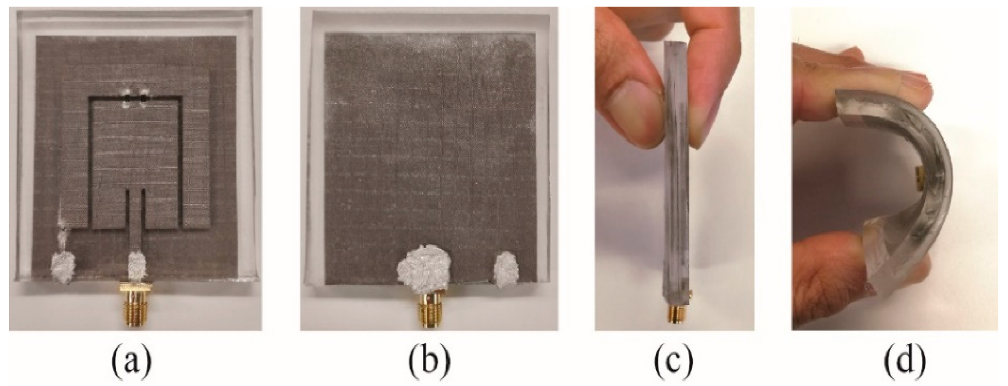
  24. Simorangkir, R.B.; Yang, Y.; Esselle, K.P.; Zeb, B.A. A method to realize robust flexible electronically tunable antennas using polymer-embedded conductive fabric. IEEE Trans. Antennas Propag. 2017, 66, 50–58. [Google Scholar] [CrossRef]
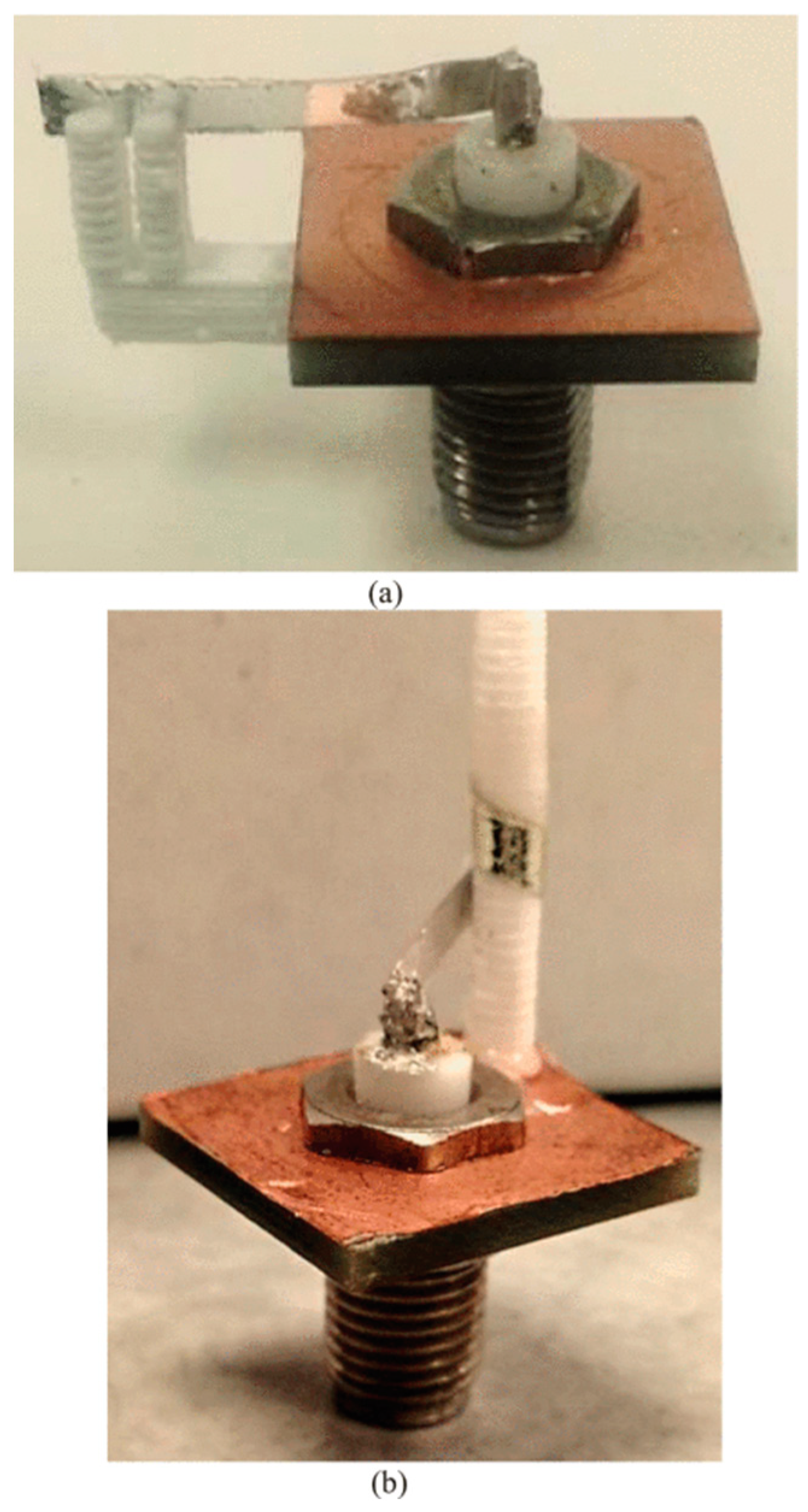
  25. Chen, S.J.; Ranasinghe, D.C.; Fumeaux, C. A robust Snap-On button solution for reconfigurable wearable textile antennas. IEEE Trans. Antennas Propag. 2018, 66, 4541–4551. [Google Scholar] [CrossRef]
  26. Kasirga, T.S.; Ertas, Y.N.; Bayindir, M. Microfluidics for reconfigurable electromagnetic metamaterials. Appl. Phys. Lett. 2009, 95, 214102. [Google Scholar] [CrossRef]
  27. King, A.J.; Patrick, J.F.; Sottos, N.R.; White, S.R.; Huff, G.H.; Bernhard, J.T. Microfluidically switched frequency reconfigurable slot antennas. IEEE Antennas Wirel. Propag. Lett. 2013, 12, 828–831. [Google Scholar] [CrossRef]
  28. Murray, C.; Franklin, R.R. Frequency Tunable Fluidic Annular Slot Antenna. In Proceedings of the 2013 IEEE Antennas and Propagation Society International Symposium (APSURSI), Orlando, FL, USA, 7–13 July 2013; pp. 386–387. [Google Scholar]
  29. Murray, C.; Franklin, R.R. Independently tunable annular slot antenna resonant frequencies using fluids. IEEE Antennas Wirel. Propag. Lett. 2014, 13, 1449–1452. [Google Scholar] [CrossRef]
  30. Chaudhari, S.; Alharbi, S.; Zou, C.; Shah, H.; Harne, R.L.; Kiourti, A. A New Class of Reconfigurable Origami Antennas Based on E-Textile Embroidery. In Proceedings of the 2018 IEEE International Symposium on Antennas and Propagation & USNC/URSI National Radio Science Meeting, Boston, MA, USA, 8–13 July 2018; pp. 183–184. [Google Scholar]
  31. Liu, X.; Yao, S.; Cook, B.S.; Tentzeris, M.M.; Georgakopoulos, S.V. An origami reconfigurable axial-mode bifilar helical antenna. IEEE Trans. Antennas Propag. 2015, 63, 5897–5903. [Google Scholar] [CrossRef]
  32. Hayes, G.J.; Liu, Y.; Genzer, J.; Lazzi, G.; Dickey, M.D. Self-folding origami microstrip antennas. IEEE Trans. Antennas Propag. 2014, 62, 5416–5419. [Google Scholar] [CrossRef]
  33. Yao, S.; Liu, X.; Georgakopoulos, S.V. Morphing origami conical spiral antenna based on the Nojima wrap. IEEE Trans. Antennas Propag. 2017, 65, 2222–2232. [Google Scholar] [CrossRef]
  34. Mazlouman, S.J.; Mahanfar, A.; Menon, C.; Vaughan, R.G. Reconfigurable axial-mode helix antennas using shape memory alloys. IEEE Trans. Antennas Propag. 2011, 59, 1070–1077. [Google Scholar] [CrossRef]
  35. Liu, X.; Yao, S.; Georgakopoulos, S.V. A Frequency Tunable Origami Spherical Helical Antenna. In Proceedings of the 2017 IEEE International Symposium on Antennas and Propagation & USNC/URSI National Radio Science Meeting, San Diego, CA, USA, 9–14 July 2017; pp. 1361–1362. [Google Scholar]
  36. Yao, S.; Liu, X.; Gibson, J.; Georgakopoulos, S.V. Deployable Origami Yagi Loop Antenna. In Proceedings of the 2015 IEEE International Symposium on Antennas and Propagation & USNC/URSI National Radio Science Meeting, Vancouver, BC, Canada, 19–24 July 2015; pp. 2215–2216. [Google Scholar]
  37. Alharbi, S.; Chaudhari, S.; Inshaar, A.; Shah, H.; Zou, C.; Harne, R.L.; Kiourti, A. E-textile origami dipole antennas with graded embroidery for adaptive RF performance. IEEE Antennas Wirel. Propag. Lett. 2018, 17, 2218–2222. [Google Scholar] [CrossRef]
  38. Lee, S.; Shah, S.I.H.; Lee, H.L.; Lim, S. Frequency reconfigurable antenna inspired by origami flasher. IEEE Antennas Wirel. Propag. Lett. 2019, 18, 1691–1695. [Google Scholar] [CrossRef]
  39. Khan, M.R.; Zekios, C.L.; Bhardwaj, S.; Georgakopoulos, S.V. Origami-Enabled Frequency Reconfigurable Dipole Antenna. In Proceedings of the 2019 IEEE International Symposium on Antennas and Propagation and USNC-URSI Radio Science Meeting, Atlanta, GA, USA, 7–12 July 2019; pp. 901–902. [Google Scholar]
  40. Shah, S.I.H.; Lim, S. Frequency switchable origami magic cube antenna. In Proceedings of the 2017 IEEE Asia Pacific Microwave Conference (APMC), Kuala Lumpar, Malaysia, 13–16 November 2017; pp. 105–107. [Google Scholar]
  41. Zainud-Deen, S.H.; Malhat, H.A.E.-A.; El-Shalaby, N.A.A.S.; Gaber, S.M. Circular polarization bandwidth reconfigurable high gain planar plasma helical antenna. IEEE Trans. Plasma Sci. 2019, 47, 4274–4280. [Google Scholar] [CrossRef]
  42. Liu, X.; Yao, S.; Georgakopoulos, S.V.; Tentzeris, M. Origami Quadrifilar Helix Antenna in UHF Band. In Proceedings of the 2014 IEEE Antennas and Propagation Society International Symposium (APSURSI), Memphis, TN, USA, 6–11 July 2014; pp. 372–373. [Google Scholar]
  43. Liu, X.; Georgakopoulos, S.V.; Tentzeris, M. A Novel Mode and Frequency Reconfigurable Origami Quadrifilar Helical Antenna. In Proceedings of the 2015 IEEE 16th Annual Wireless and Microwave Technology Conference (WAMICON), Cocoa Beach, FL, USA, 13–15 April 2015; pp. 1–3. [Google Scholar]
  44. Liu, X.; Yao, S.; Georgakopoulos, S.V. Frequency Reconfigurable Origami Quadrifilar Helical Antenna with Reconfigurable Reflector. In Proceedings of the 2015 IEEE International Symposium on Antennas and Propagation & USNC/URSI National Radio Science Meeting, Vancouver, BC, Canada, 19–24 July 2015; pp. 2217–2218. [Google Scholar]
  45. Liu, X.; Yao, S.; Gonzalez, P.; Georgakopoulos, S.V. A Novel Ultra-Wideband Origami Reconfigurable Quasi-Taper Helical Antenna. In Proceedings of the 2016 IEEE International Symposium on Antennas and Propagation (APSURSI), Fajardo, Puerto Rico, 26 June–1 July 2016; pp. 839–840. [Google Scholar]
  46. Liu, X.; Yao, S.; Russo, N.; Georgakopoulos, S.V. Reconfigurable helical antenna based on origami neoprene with high radiation efficiency. In Proceedings of the 2018 IEEE International Symposium on Antennas and Propagation & USNC/URSI National Radio Science Meeting, Boston, MA, USA, 8–13 July 2018; pp. 185–186. [Google Scholar]
  47. Liu, X.; Yao, S.; Russo, N.; Georgakopoulos, S. Tri-band Reconfigurable Origami Helical Array. In Proceedings of the 2018 IEEE International Symposium on Antennas and Propagation & USNC/URSI National Radio Science Meeting, Boston, MA, USA, 8–13 July 2018; pp. 1231–1232. [Google Scholar]
  48. Carrara, G.P.; Russo, N.E.; Zekios, C.L.; Georgakopoulos, S.V. A Deployable and Reconfigurable Origami Antenna for extended Mobile Range. In Proceedings of the 2019 IEEE International Symposium on Antennas and Propagation and USNC-URSI Radio Science Meeting, Atlanta, GA, USA, 7–12 July 2019; pp. 453–454. [Google Scholar]
  49. Liu, X.; Yao, S.; Georgakopoulos, S.V.; Cook, B.S.; Tentzeris, M.M. Reconfigurable Helical Antenna Based on an Origami Structure for Wireless communication system. In Proceedings of the 2014 IEEE MTT-S International Microwave Symposium (IMS2014), Tampa, FL, USA, 1–6 June 2014; pp. 1–4. [Google Scholar]
  50. Yao, S.; Bao, K.; Liu, X.; Georgakopoulos, S.V. Tunable UHF Origami Spring Antenna with Actuation System. In Proceedings of the 2017 IEEE International Symposium on Antennas and Propagation & USNC/URSI National Radio Science Meeting, San Diego, CA, USA, 9–14 July 2017; pp. 325–326. [Google Scholar]
  51. Yao, S.; Georgakopoulos, S.V.; Cook, B.; Tentzeris, M. A Novel Reconfigurable Origami Accordion Antenna. In Proceedings of the 2014 IEEE MTT-S International Microwave Symposium (IMS2014), Tampa, FL, USA, 1–6 June 2014; pp. 1–4. [Google Scholar]
  52. Cardoso, J.; Safaai-Jazi, A. Spherical helical antenna with circular polarisation over a broad beam. Electron. Lett. 1993, 29, 325–326. [Google Scholar] [CrossRef]
  53. Seiler, S.R.; Bazzan, G.; Fuchi, K.; Alanyak, E.J.; Gillman, A.S.; Reich, G.W.; Buskohl, P.R.; Pallampati, S.; Sessions, D.; Grayson, D.; et al. Physical Reconfiguration of an origami-inspired deployable Microstrip Patch Antenna Array. In Proceedings of the 2017 IEEE International Symposium on Antennas and Propagation & USNC/URSI National Radio Science Meeting, San Diego, CA, USA, 9–14 July 2017; pp. 2359–2360. [Google Scholar]
  54. Saeed, S.M.; Balanis, C.A.; Birtcher, C.R.; Durgun, A.C.; Shaman, H.N. Wearable flexible reconfigurable antenna integrated with artificial magnetic conductor. IEEE Antennas Wirel. Propag. Lett. 2017, 16, 2396–2399. [Google Scholar] [CrossRef]
  55. Mohamadzade, B.; Hashmi, R.M.; Simorangkir, R.B.; Gharaei, R.; Rehman, S.U.; Abbasi, Q.H. Recent advances in fabrication methods for flexible antennas in wearable devices: State of the art. Sensors 2019, 19, 2312. [Google Scholar] [CrossRef] [Green Version]
  56. Mohamadzade, B.; Simorangkir, R.B.; Hashmi, R.M.; Lalbakhsh, A. A conformal ultrawideband antenna with monopole-like radiation patterns. IEEE Trans. Antennas Propag. 2020, 68, 6383–6388. [Google Scholar] [CrossRef]
  57. Mohamadzade, B.; Simorangkir, R.B.; Hashmi, R.M.; ChaoOger, Y.; Zhadobov, M.; Sauleau, R. A conformal band-notched ultrawideband antenna with monopole-like radiation characteristics. IEEE Antennas Wirel. Propag. Lett. 2019, 19, 203–207. [Google Scholar] [CrossRef]
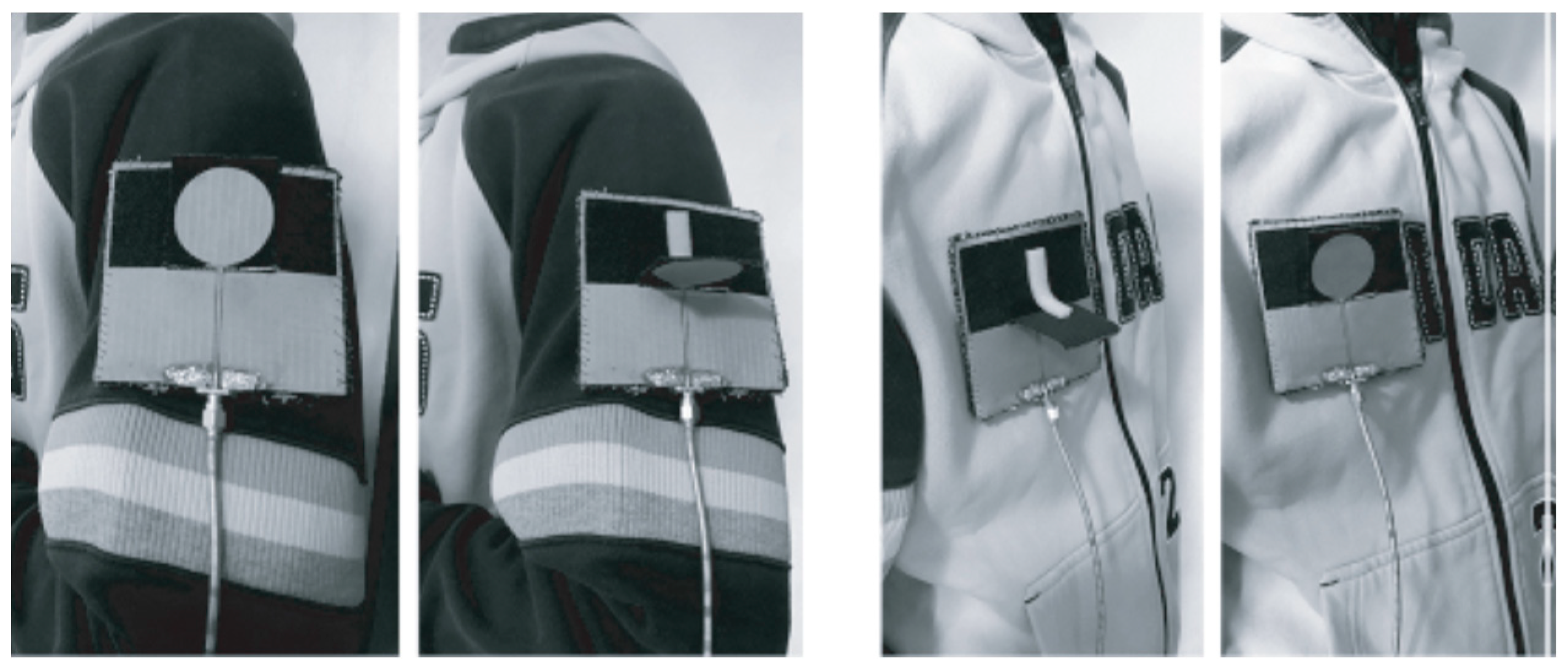
  58. Shakhirul, M.; Jusoh, M.; Ismail, A.; Kamarudin, M.; Rahim, H.A.; Sabapathy, T. Reconfigurable Frequency with Circular Polarization for on-Body Wearable Textile Antenna. In Proceedings of the 2016 10th European Conference on Antennas and Propagation (EuCAP), Davos, Switzerland, 10–15 April 2016; pp. 1–4. [Google Scholar]
  59. Dang, Q.H.; Chen, S.J.; Ranasinghe, D.C.; Fumeaux, C. A Reconfiguration Module with Coplanar Snap-On Connection for Wearable Textile Antennas. In Proceedings of the 2019 IEEE Asia-Pacific Microwave Conference (APMC), Singapore, Singapore, 10–13 December 2019; pp. 613–615. [Google Scholar]
  60. Kingsley, N.; Anagnostou, D.E.; Tentzeris, M.; Papapolymerou, J. RF MEMS sequentially reconfigurable Sierpinski antenna on a flexible organic substrate with novel dc-biasing technique. J. Microelectromechan. Syst. 2007, 16, 1185–1192. [Google Scholar] [CrossRef]
  61. Bairavasubramanian, R.; Kingsley, N.; DeJean, G.; Wang, G.; Anagnostou, D.E.; Tentzeris, M.; Papapolymerou, J. Recent Developments on Lightweight, Flexible, Dual Polarization/Frequency Phased Arrays Using RF Mems Switches on LCP Multilayer Substrates for Remote Sensing of Precipitation. In Proceedings of the 6th Annual NASA Earth Science Technology Conference (ESTC 2006), College Park, MD, USA, 27–29 June 2006. [Google Scholar]
  62. Anagnostou, D.E.; Bairavasubramanian, R.; DeJean, G.; Wang, G.; Kingsley, N.; Tentzeris, M.; Papapolymerou, J. Development of a Dual-Frequency, Dual-Polarization, Flexible and Deployable Antenna Array for Weather Applications. In Proceedings of the 15th IST Mobile & Wireless Communication Summit, Myconos, Greece, 4–8 June 2006. [Google Scholar]
  63. Jang, T.; Zhang, C.; Youn, H.; Zhou, J.; Guo, L.J. Semitransparent and flexible mechanically reconfigurable electrically small antennas based on tortuous metallic micromesh. IEEE Trans. Antennas Propag. 2016, 65, 150–158. [Google Scholar] [CrossRef]
  64. Saghati, A.P.; Batra, J.S.; Kameoka, J.; Entesari, K. Miniature and reconfigurable CPW folded slot antennas employing liquid-metal capacitive loading. IEEE Trans. Antennas Propag. 2015, 63, 3798–3807. [Google Scholar] [CrossRef]
  65. Saghati, A.P.; Batra, J.; Kameoka, J.; Entesari, K. A Microfluidically-Switched CPW Folded Slot Antenna. In Proceedings of the 2014 IEEE Antennas and Propagation Society International Symposium (APSURSI), Memphis, TN, USA, 6–11 July 2014; pp. 557–558. [Google Scholar]
  66. So, J.-H.; Thelen, J.; Qusba, A.; Hayes, G.J.; Lazzi, G.; Dickey, M.D. Reversibly deformable and mechanically tunable fluidic antennas. Adv. Funct. Mater. 2009, 19, 3632–3637. [Google Scholar] [CrossRef]
  67. Mazlouman, S.J.; Jiang, X.J.; Mahanfar, A.; Menon, C.; Vaughan, R.G. A Reconfigurable Patch Antenna Using Liquid Metal Embedded in a Silicone Substrate. IEEE Trans. Antennas Propag. 2011, 59, 4406–4412. [Google Scholar] [CrossRef]
  68. Zandvakili, M.; Honari, M.M.; Sameoto, D.; Mousavi, P. Microfluidic Liquid Metal Based Mechanically Reconfigurable Antenna Using Reversible Gecko Adhesive Based Bonding. In Proceedings of the 2016 IEEE MTT-S International Microwave Symposium (IMS), San Francisco, CA, USA, 22–27 May 2016; pp. 1–4. [Google Scholar]
  69. Su, W.; Nauroze, S.A.; Ryan, B.; Tentzeris, M.M. Novel 3d Printed Liquid-Metal-Alloy Microfluidics-Based Zigzag and Helical Antennas for Origami Reconfigurable Antenna “Trees”. In Proceedings of the 2017 IEEE MTT-S International Microwave Symposium (IMS), Honololu, HI, USA, 4–9 June 2017; pp. 1579–1582. [Google Scholar]
  70. Georgakopoulos, S.V. Reconfigurable Origami Antennas. In Proceedings of the 2019 International Applied Computational Electromagnetics Society Symposium (ACES), Miami, FL, USA, 14–19 April 2019; pp. 1–2. [Google Scholar]
  71. Fuchi, K.; Buskohl, P.R.; Joo, J.J.; Reich, G.W.; Vaia, R.A. Resonance Tuning of RF Devices through Origami Folding. In Proceedings of the 20th International Conference on Composite Materials, Copenhagen, Denmark, 19–24 July 2015; pp. 1–10. [Google Scholar]
  72. Liu, X.; Georgakopoulos, S.V.; Rao, S. A design of an origami reconfigurable QHA with a foldable reflector [antenna applications corner]. IEEE Antennas Propag. Mag. 2017, 59, 78–105. [Google Scholar] [CrossRef]
  73. Liu, X.; Zekios, C.L.; Georgakopoulos, S.V. Analysis of a packable and tunable origami multi-radii helical antenna. IEEE Access 2019, 7, 13003–13014. [Google Scholar] [CrossRef]
  74. Shah, S.I.H.; Lim, S. A dual band frequency reconfigurable origami magic cube antenna for wireless sensor network applications. Sensors 2017, 17, 2675. [Google Scholar] [CrossRef] [Green Version]
  75. Liu, C.-X.; Zhang, Y.-J.; Li, Y. Precisely manipulated origami for consecutive frequency reconfigurable antennas. Smart Mater. Struct. 2019, 28, 095020. [Google Scholar] [CrossRef]
  76. Lee, S.; Lee, M.; Lim, S. Frequency reconfigurable antenna actuated by three-storey tower kirigami. Extrem. Mech. Lett. 2020, 39, 100833. [Google Scholar] [CrossRef]
  77. Nogi, M.; Komoda, N.; Otsuka, K.; Suganuma, K. Foldable nanopaper antennas for origami electronics. Nanoscale 2013, 5, 4395–4399. [Google Scholar] [CrossRef]
  78. Jilani, S.F.; Rahimian, A.; Alfadhl, Y.; Alomainy, A. Low-profile flexible frequency-reconfigurable millimetre-wave antenna for 5G applications. Flex. Print. Electron. 2018, 3, 035003. [Google Scholar] [CrossRef]
  79. Jilani, S.F.; Greinke, B.; Hao, Y.; Alomainy, A. Flexible Millimetre-Wave Frequency Reconfigurable Antenna for Wearable Applications in 5G Networks. In Proceedings of the 2016 URSI International Symposium on Electromagnetic Theory (EMTS), Espoo, Finland, 14–18 August 2016; pp. 846–848. [Google Scholar]
  80. Radha, S.; Rao, P.H. Pattern Reconfigurable Ultra Wideband Thin Antenna. In Proceedings of the 2012 Third International Conference on Computing, Communication and Networking Technologies (ICCCNT’12), Coimbatore, India, 26–28 July 2012; pp. 1–5. [Google Scholar]
  81. Jais, M.; Jamlos, M.; Jusoh, M.; Sabapathy, T.; Kamarudin, M. 2.45 GHz Beam-Steering Textile Antenna for WBAN Application. In Proceedings of the 2013 IEEE Antennas and Propagation Society International Symposium (APSURSI), Orlando, FL, USA, 7–13 July 2013; pp. 200–201. [Google Scholar]
  82. He, X.; Gao, P.; Zhu, Z.; You, S.; Wang, P. A flexible pattern reconfigurable antenna for WLAN wireless systems. J. Electromagn. Waves Appl. 2019, 33, 782–793. [Google Scholar] [CrossRef]
  83. Mohamadzade, B.; Simorangkir, R.B.; Hashmi, R.M.; Shrestha, S. Low-Profile Pattern Reconfigurable Antenna for Wireless Body Area Networks. In Proceedings of the 2019 International Conference on Electromagnetics in Advanced Applications (ICEAA), Granada, Spain, 9–13 September 2019; pp. 546–547. [Google Scholar]
  84. Mohamadzade, B.; Simorangkir, R.B.; Hashmi, R.M.; Gharaei, R.; Lalbakhsh, A. Monopole-like and semi-directional reconfigurable pattern antenna for wireless body area network applications. Microw. Opt. Technol. Lett. 2019, 61, 2760–2765. [Google Scholar] [CrossRef]
  85. Ha, S.-J.; Jung, Y.-B.; Kim, Y.; Jung, C.W. Reconfigurable beam-steering antenna using dipole and loop combined structure for wearable applications. ETRI J. 2012, 34, 1–8. [Google Scholar] [CrossRef]
  86. Yan, S.; Vandenbosch, G.A. Radiation pattern-reconfigurable wearable antenna based on metamaterial structure. IEEE Antennas Wirel. Propag. Lett. 2016, 15, 1715–1718. [Google Scholar] [CrossRef]
  87. Yan, S.; Vandenbosch, G.A. Wearable Pattern Reconfigurable Patch Antenna. In Proceedings of the 2016 IEEE International Symposium on Antennas and Propagation (APSURSI), Puerto Rico, USA, 26 June–1 July 2016; pp. 1665–1666. [Google Scholar]
  88. Mendes, C.; Peixeiro, C. A dual-mode single-band wearable microstrip antenna for body area networks. IEEE Antennas Wirel. Propag. Lett. 2017, 16, 3055–3058. [Google Scholar] [CrossRef]
  89. Di Natale, A.; Di Giampaolo, E. A reconfigurable all-textile wearable UWB antenna. Prog. Electromagn. Res. 2020, 103, 31–43. [Google Scholar] [CrossRef]
  90. Moghadas, H.; Zandvakili, M.; Sameoto, D.; Mousavi, P. Beam reconfigurable aperture antenna by stretching or reshaping of a flexible surface. IEEE Antennas Wirel. Propag. Lett. 2016, 16, 1337–1340. [Google Scholar] [CrossRef]
  91. Shah, S.I.H.; Ghosh, S.; Lim, S. A Novel Bio Inspired Pattern Reconfigurable Quasi-Yagi Helical Antenna using Origami DNA. In Proceedings of the 2018 International Symposium on Antennas and Propagation (ISAP), Busan, Korea, 23–26 October 2018. [Google Scholar]
  92. Shah, S.I.H.; Lim, S. Thermally beam-direction-and beamwidth switchable monopole antenna using origami reflectors with smart shape memory polymer hinges. IEEE Antennas Wirel. Propag. Lett. 2019, 18, 1696–1700. [Google Scholar] [CrossRef]
  93. Shah, S.I.H.; Tentzeris, M.M.; Lim, S. A deployable quasiyagi monopole antenna using three origami magic spiral cubes. IEEE Antennas Wirel. Propag. Lett. 2018, 18, 147–151. [Google Scholar] [CrossRef]
  94. Hatsopoulos, N.G.; Warren, W.H., Jr. Resonance tuning in rhythmic arm movements. J. Mot. Behav. 1996, 28, 3–14. [Google Scholar] [CrossRef]
  95. Xu, Y.; Kim, Y.; Tentzeris, M.M.; Lim, S. Bi-directional loop antenna array using magic cube origami. Sensors 2019, 19, 3911. [Google Scholar] [CrossRef] [Green Version]
  96. Jais, M.I.; Jamlos, M.; Jusoh, M.; Sabapathy, T.; Kamarudin, M.R. A novel 1.575-GHz dual-polarization textile antenna for gps application. Microw. Opt. Technol. Lett. 2013, 55, 2414–2420. [Google Scholar] [CrossRef]
  97. Lee, C.M.; Jung, C.W. Radiation-pattern-reconfigurable antenna using monopole-loop for Fitbit flex wristband. IEEE Antennas Wirel. Propag. Lett. 2014, 14, 269–272. [Google Scholar] [CrossRef]
  98. Liu, X.; Yao, S.; Georgakopoulos, S.V. Mode Reconfigurable Bistable Spiral Antenna Based on Kresling Origami. In Proceedings of the 2017 IEEE International Symposium on Antennas and Propagation & USNC/URSI National Radio Science Meeting, San Diego, CA, USA, 9–14 July 2017; pp. 413–414. [Google Scholar]
  99. Bhattacharjee, S.; Teja, S.; Midya, M.; Chaudhuri, S.B.; Mitra, M. Dual Band Dual Mode Triangular Textile Antenna for Body-Centric Communications. In Proceedings of the 2019 URSI Asia-Pacific Radio Science Conference (AP-RASC), New Delhi, India, 9–15 March 2019; pp. 1–4. [Google Scholar]
  100. Langley, R.J.; Ford, K.L.; Lee, H.-J. Switchable on/off-Body Communication at 2.45 GHz Using Textile Microstrip Patch Antenna on Stripline. In Proceedings of the 2012 6th European Conference on Antennas and Propagation (EUCAP), Prague, Czech Republic, 26–30 March 2012; pp. 728–731. [Google Scholar]
  101. Lee, H.; Choi, J. A Polarization Reconfigurable Textile Patch Antenna for Wearable IOT Applications. In Proceedings of the 2017 International Symposium on Antennas and Propagation (ISAP), Phuket, Thailand, 30 October–2 November 2017; pp. 1–2. [Google Scholar]
  102. Jais, M.; Jamlos, M.; Jusoh, M.; Sabapathy, T.; Nayan, M.; Shahadah, A.; Rahim, H.A.; Ismail, I.; Fuad, F. 1.575 GHz Dual-Polarization Textile Antenna (DPTA) for GPS Application. In Proceedings of the 2013 IEEE Symposium on Wireless Technology & Applications (ISWTA), Kuching, Malaysia, 22–25 September 2013; pp. 376–379. [Google Scholar]
  103. Yao, S.; Georgakopoulos, S.V. Origami segmented helical antenna with switchable sense of polarization. IEEE Access 2017, 6, 4528–4536. [Google Scholar] [CrossRef]
  104. Yao, S.; Liu, X.; Georgakopoulos, S.V.; Schamp, R. Polarization Switchable Origami Helical Antenna. In Proceedings of the 2016 IEEE International Symposium on Antennas and Propagation (APSURSI), Fajardo, Puerto Rico, 26 June–1 July 2016; pp. 1667–1668. [Google Scholar]
  105. Yao, S.; Liu, X.; Georgakopoulos, S.V. Segmented Helical Antenna with Reconfigurable Polarization. In Proceedings of the 2017 IEEE International Symposium on Antennas and Propagation & USNC/URSI National Radio Science Meeting, San Diego, CA, USA, 9–14 July 2017; pp. 2207–2208. [Google Scholar]
  106. Tsolis, A.; Michalopoulou, A.; Alexandridis, A.A. Use of conductive zip and velcro as a polarisation reconfiguration means of a textile patch antenna. IET Microw. Antennas Propag. 2020, 14, 684–693. [Google Scholar] [CrossRef]
  107. Liu, X.; Yao, S.; Georgakopoulos, S.V. Reconfigurable Origami Equiangular Conical Spiral Antenna. In Proceedings of the 2015 IEEE International Symposium on Antennas and Propagation & USNC/URSI National Radio Science Meeting, Vancouver, BC, Canada, 19–24 July 2015; pp. 2263–2264. [Google Scholar]
  108. Vasina, P.; Lacik, J. Textile Linear Polarization Reconfigurable Ring Slot Antenna for 5.8 GHz Band. In Proceedings of the 2017 Conference on Microwave Techniques (COMITE), Brno, Czech Republic, 20–21 April 2017; pp. 1–4. [Google Scholar]
  109. Saha, P.; Mitra, D.; Parui, S.K.A. frequency and polarization agile disc monopole wearable antenna for medical applications. Radioengineering 2020, 29, 75. [Google Scholar] [CrossRef]
  110. Chen, S.J.; Ranasinghe, D.C.; Fumeaux, C. A Polarization/Frequency Interchangeable Patch for a Modular Wearable Textile Antenna. In Proceedings of the 2017 11th European Conference on Antennas and Propagation (EUCAP), Paris, France, 19–24 March 2017; pp. 2483–2486. [Google Scholar]
  111. Zhu, Z.; Wang, P.; You, S.; Gao, P. A flexible frequency and pattern reconfigurable antenna for wireless systems. Prog. Electromagn. Res. 2018, 76, 63–70. [Google Scholar]
  112. da Conceição Andrade, A.; Fonseca, I.P.; Jilani, S.F.; Alomainy, A. Reconfigurable Textile-Based Ultra-Wideband Antenna for Wearable Applications. In Proceedings of the 2016 10th European Conference on Antennas and Propagation (EuCAP), Davos, Switzerland, 10–15 April 2016; pp. 1–4. [Google Scholar]
  113. Gibson, J.S.; Liu, X.; Georgakopoulos, S.V.; Wie, J.J.; Ware, T.H.; White, T.J. Reconfigurable antennas based on self-morphing liquid crystalline elastomers. IEEE Access 2016, 4, 2340–2348. [Google Scholar] [CrossRef]
  114. Nojima, T. Origami Modeling of Functional Structures Based on Organic Patterns. Mater’s Thesis, Kyoto University, Kyoto, Japan, 2002. [Google Scholar]
  115. Yao, S.; Liu, X.; Georgakopoulos, S.V. A Mode Reconfigurable Nojima Origami Antenna. In Proceedings of the 2015 IEEE International Symposium on Antennas and Propagation & USNC/URSI National Radio Science Meeting, Vancouver, BC, Canada, 19–25 July 2015; pp. 2237–2238. [Google Scholar]
Figure 1. Categorization of reconfiguration techniques for all types of antennas.
Electronics 09 01375 g001
Figure 2. The fabricated frequency-reconfigurable antenna on polydimethylsiloxane (PDMS) substrate in [24]: (a) front view; (b) back view; (c) side view; (d) bending position.
Electronics 09 01375 g002
Figure 3. The frequency reconfigurable antenna based on changing the antenna shape (Origami Magic Cube): (a) unfolded; (b) folded [74].
Electronics 09 01375 g003
Figure 4. Fabricated prototype of the pattern-reconfigurable antenna on flexible polyimide in [85].
Electronics 09 01375 g004
Figure 5. Fabricated proposed antenna array based on magic cube origami for: (a) single antenna and cube (b) two antennas and (c) three antennas [95].
Electronics 09 01375 g005
Figure 6. The measurement set-up for proposed fully textile reconfigurable UWB antenna with two monopole-like and a microstrip-like patterns ([89], reproduced courtesy of The Electromagnetics Academy).
Electronics 09 01375 g006
Figure 7. The prototype of the bifilar segmented helical antennas at (a) left-handed and (b) right-handed angles [103].
Electronics 09 01375 g007
Figure 8. Fabricated prototype of the frequency and polarization-reconfigurable antenna on jean substrate in [109].
Electronics 09 01375 g008
Figure 9. The fabricated frequency-reconfigurable antenna based on textile in [1]: (a) front view; (b) back view.
Electronics 09 01375 g009
Figure 10. Pattern and frequency-reconfigurable antenna based on liquid crystalline elastomers: (a) straight statues; (b) helix structure with 1.1-turn [113].
Electronics 09 01375 g010
Table 1. Comparison of methods and materials used in different kinds of flexible frequency-reconfigurable antennas, along with corresponding performance.
Ref.Antenna TypeReconfigurability MethodNo of StatesUsed MaterialsFreq. (GHz)Gain (dBi)Eff. (%)BW (%) Dimension   ( λ m i n   ×   λ m i n ) Height ( λ m i n )
Min.Max.Min.Max.Min.Max.Min.Max.
[1]patchelectrical switch/slot modification on ground6ShieldIt Super and Felt1.572.550.24.817472.9190.59 × 0.510.006
[20]patchelectrical switch/connecting two patches2copper tape, Denim2.4553.173.55N/AN/A2.55.850.40 × 0.190.008
[21]loop/monopoleelectrical switch/geometry morphing3transparent PETP2.43.41.93.282.89712.2520.940.264 × 0.40.001
[27]dipolephysical/microfluidic based2S-glass, copper-tape, EGaIn3.845.34N/AN/AN/AN/AN/AN/A1.8 × 1.8N/A
[24]patchelectrical switch/parasitic patchContinuousPolymer, Conductive fabric2.32.682.93.340.346.10.30.40.4 × 0.430.042
[28]slot antennaphysical/change of permittivity by injection3FR4, PDMS, copper3.057.9N/AN/AN/AN/AN/AN/AN/A0.015
[31]helicalphysical/height of structure3copper tape, sketching-paper0.8634.696.79N/AN/AN/AN/A0.13 × 0.130.07, 0.44, 0.78
[32]monopole/microstripphysical/changing the type of antenna2copper-clad RT/duroid 58701.53.5N/AN/AN/AN/A13.980N/AN/A
[50]Spring Antennaphysical/height of structure6Copper tape, paper1.11.49~10N/AN/AN/AN/AN/A0.22 to 0.53
[66]patchphysical/based on injection alloys, reconfigurability by stretching upContinuousEGaIn, PDMS 1.61.85N/AN/AN/AN/A12.516.50.053 × 0.29
to 0.053 × 0.35
0.005
Table 2. Comparison of methods and materials used in different kinds of flexible pattern-reconfigurable antennas, along with corresponding performance.
Ref.Antenna TypeReconfigurability MethodNo of StatesFreq. (GHz)Used MaterialsGain (dBi)Eff. (%)BW (%)
Dimension   ( λ m i n × λ m i n )
Height (λmin)
Min.Max.Min.Max.Min.Max.
[81]patchelectrical switch/connecting parasitic patches to the main patch42.45ShieldIt Super, FeltN/AN/AN/AN/AN/AN/A0.72 × 0.720.016
[82]monopoleelectrical switch/connecting surrounding elements to the main patch22.40–2.48Rogers58800.50.77778N/A3.20.28 × 0.20.001
[85]dipole, loopelectrical switch/combination of the pattern of two antennas32.47–2.53Polyimide1.962.48N/AN/AN/A2.40.2 × 0.350.004
[86]patchelectrical switch/connecting patch to the ground22.4Felt, conductive textile23.93849.54.88.50.78 × 0.780.023
[88]patchelectrical switch/switching between feeding ports22.45felt and Copper Polyester Taffeta2.95.265724.14.90.64 × 0.640.03
[90]array of dipolesPhysical/elongation of patch which is based on liquid metal312.5EGaIn, platinum-cured thermoset siliconeN/AN/AN/AN/AN/AN/AN/AN/A
[91]helicalPhysical/folding and unfolding42.2copper film, PET7.59.5N/AN/AN/AN/AN/AN/A
[92]monopolePhysical/folding and unfolding origami reflectors82.4copper-clad FR4 substrate4.511869816302.2 × 2.2 to 0.73 × 0.73~0 to 0.73
[93] monopolePhysical/folding and unfolding two other directors on magic cube41.9copper film, paper1.97.364N/AN/A210.24 × 0.240.06 to 0.72
[95]loop Physical/magic cube origami31.39Copper tape, Kapton4.035.53899710180.21 × 0.21 to 0.21 × 0.630.21
Table 3. Characteristics of materials with relevance to reconfiguration element used for flexible and conformal reconfigurable antennas along with corresponding performance.
Reconfiguration ElementRef.Material NameMaterial TypeDielectric Constant (Relative Permittivity)Conductivity (S/m) or Resistivity (ohms/sq)Suitable for Folding/BendingSuitable for Sustained Folding/BendingFreq. (GHz)Gain (dBi)Eff. (%)BW (%) Dimension   ( λ m i n × λ m i n ) Height ( λ m i n )
ε r t a n   δ Min.Max.Min.Max.Min.Max.Min.Max.
-[1]ShieldIt SuperTextile--1.18 × 10⁵ S/mYesNo1.572.550.24.817472.915.40.59 × 0.510.006
FeltTextile1.220.016-
[17]GrapheneConductive Ink--0.37 × 10⁵ S/mYesNo3.036.1302.0954.974N/AN/A0.46 × 0.540.015
Polyvinyl chloride foam, polyimide filmPolymer, Foam1.5,3.5--
[20]Copper tapeCopper---YesNo2.4553.173.55N/AN/A2.55.850.40 × 0.190.008
DenimFabric1.680.03-
[24]a nylon ripstop fabricFabric--0.01 Ω/sqYesNo2.32.682.93.340.346.10.30.40.4 × 0.430.042
PDMSPolymer2.820.023-
[25]ShieldexFabric--0.009 Ω/sqYesNo2.16.2−0.98.83090N/AN/A0.42 × 0.420.04
C-Foam PF-4Foam1.060.0001-
Conductive fluid as a switch[27]EGaInLiquid Metal--3.4 × 10⁶ S/mYesYes3.845.34N/AN/AN/AN/AN/AN/A1.8 × 1.8N/A
S-glassFibers & Textile3.4--
Microfluidic antenna-physical deformation[66]EGaInLiquid Metal--3.4 × 10⁴ S/mYesYes1.61.85N/AN/AN/AN/A12.516.50.053 × 0.29 to 0.053 × 0.350.005
PDMSPolymer2.670.0375-
[67]GalinstanLiquid Metal--3.46 × 10⁶ S/mYesYes1.33N/AN/A6580N/AN/A0.17 × 0.650.02
TC5005Silicone2.8–3.1--
[90]EGaInLiquid Metal--3.4 × 10⁴ S/mYesYesN/AN/AN/AN/AN/AN/AN/AN/AN/AN/A
Platinum-cured thermoset siliconePolymer2.20.08-
Origami Based antenna-physical deformation[37]E-threadsThreads--1.9 Ω/mYesYes0.761.015−2.50N/AN/A12140.42 × 0.025N/A
OrganzaFabric (~1)--
[74]Copper film Metal- 4.4 × 10⁵ S/mYesNo0.92.51.13.28N/AN/A14200.15 × 0.150.0006 to 0.15
PaperPaper2.20.04-
[75]Copper sheetsMetal---YesYes0.951.6N/AN/AN/AN/AN/AN/A0.44 × 0.12N/A
Verowhite Polymer2.80.01-
[92]CopperMetal--5.96 × 10⁵ S/mYesYes2.44.511869816302.2 × 2.2 to 0.73 × 0.73~0 to 0.73
FR4 substrateComposite 4.4--

