Article

Using Augmented Reality and Internet of Things for Control and Monitoring of Mechatronic Devices

1
Faculty of Informatics, Pan-European University, 851 05 Bratislava, Slovakia
2
Faculty of Electrical Engineering and Information Technology, Slovak University of Technology in Bratislava, 812 19 Bratislava, Slovakia
*
Author to whom correspondence should be addressed.
Electronics 2020, 9(8), 1272; https://doi.org/10.3390/electronics9081272
Submission received: 19 July 2020 / Revised: 4 August 2020 / Accepted: 6 August 2020 / Published: 7 August 2020
(This article belongs to the Special Issue Human Computer Interaction for Intelligent Systems)

Abstract

:
At present, computer networks are no longer used to connect just personal computers. Smaller devices can connect to them even at the level of individual sensors and actuators. This trend is due to the development of modern microcontrollers and singleboard computers which can be easily connected to the global Internet. The result is a new paradigm—the Internet of Things (IoT) as an integral part of the Industry 4.0; without it, the vision of the fourth industrial revolution would not be possible. In the field of digital factories it is a natural successor of the machine-to-machine (M2M) communication. Presently, mechatronic systems in IoT networks are controlled and monitored via industrial HMI (human-machine interface) panels, console, web or mobile applications. Using these conventional control and monitoring methods of mechatronic systems within IoT networks, this method may be fully satisfactory for smaller rooms. Since the list of devices fits on one screen, we can monitor the status and control these devices almost immediately. However, in the case of several rooms or buildings, which is the case of digital factories, ordinary ways of interacting with mechatronic systems become cumbersome. In such case, there is the possibility to apply advanced digital technologies such as extended (computer-generated) reality. Using these technologies, digital (computer-generated) objects can be inserted into the real world. The aim of this article is to describe design and implementation of a new method for control and monitoring of mechatronic systems connected to the IoT network using a selected segment of extended reality to create an innovative form of HMI.

1. Introduction

Extended reality, as a modern technology, is used in Industry 4.0 to virtualize the efficient design of optimal production structures and work operations with their effective ergonomic evaluation and design [1,2]. New forms of process monitoring, control, diagnostics and visualization are currently being sought in digital factories [3]. It is the extended reality that brings such forms [4].
Under extended reality we understand virtual, augmented and mixed reality [5]. At present, there is no general consensus on the distinction between augmented and mixed reality. There are several definitions.
The first definition is the definition from The Foundry, which develops software for 3D modeling and texturing [6]. This definition is often used in industrial practice.
Virtual reality (VR) replicates an environment that simulates a physical presence in places in the real world or an imagined world, allowing the user to interact in that world [6]. Devices for virtual reality are Oculus Rift, Oculus Quest, HTC Vive, and so forth [7].
Augmented reality (AR) is a live, direct or indirect view of a physical, real-world environment whose elements are augmented (or supplemented) by computer-generated sensory input such as sound, video, graphics or GPS data [6]. Augmented reality is an overlay of content on the real world, but that content is not anchored to or part of it. The real-world content and the CG content are not able to respond to each other [8].
Mixed reality (MR) is the merging of real and virtual worlds to produce new environments and visualisations where physical and digital objects co-exist and interact in real time. MR is an overlay of synthetic content on the real world that is anchored to and interacts with the real world. The key characteristic of MR is that the synthetic content and the real-world content can react to each other in real time [6]. Technologies for mixed reality are Microsoft HoloLens (Windows Mixed Reality platform), Apple ARKit and Android ARCore [8].
Another definition is often used in scientific teams rather than in industrial practice. In 1994, the authors Milgram and Kishiho [9] introduced the spectrum between real and virtual environment—reality-virtuality continuum (Figure 1). This continuum defines a mix of real and virtual world. They understand mixed reality as anything between real environment and full virtual reality. Between reality and virtual reality, they distinguish between augmented reality, which is practically identical to augmented reality according to The Foundry definition, and augmented virtuality. It can be stated that augmented virtuality corresponds to mixed reality according to The Foundry definition.

1.1. Motivation

The current emerging trend in the Internet of Things has an impact not only in applications for households [10], smart buildings and services, but also on industries and manufacturing [11,12]. The application of IoT principles in industries is called the Industrial Internet of Things (IIoT). In this case, individual machine parts, sensors and actuators act as interconnected devices [13]. In particular, the interconnection of devices should be wireless and bring about new possibilities for their mutual interaction as well as for their diagnostics, control and provision of advanced services.
The research included several meetings and discussions with industry partners who demanded the Internet of Things to be connected to the augmented or mixed reality. It has shown that it is an obvious fact that integration of augmented and mixed reality technologies into production processes in digital factories is inevitable.
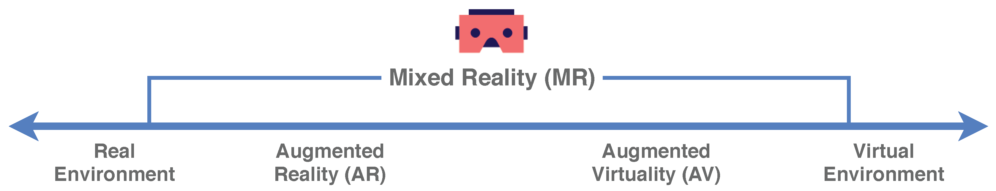
  • British company dealing with the implementation of Industry 4.0 principles
    One of the modern trends in the industrial field is the use of increasingly powerful, more durable and more affordable mobile devices, such as a smartphone or tablet. Such devices allow the use of modern technologies that have not been widely used in industry so far. We mean augmented and mixed reality and its applications for control and monitoring of devices. The use of augmented or mixed reality creates a qualitatively new and better way of solving HMI. In conventional approaches, it is necessary to select a specific device (sensor, actuator ⋯) on the display device so we need to know its specific location in the production hall or its ID. After selecting the device, the required data (for example in the form of a graph or a table) is displayed on the display unit. When using the augmented or mixed reality application, it is possible to operatively search for individual sensors within the production hall environment and interactively display the required values or change the settings and parameters of the given device via the display unit. An interesting feature would be the advanced functionality that would allow you to see in the environment which device the selected device is connected to or is forwarding data. It is the localization and identification of individual sensors and actuators that is currently an open problem that can be solved by several approaches.
  • Slovak company dealing with tire diagnostics
    The use of augmented or mixed reality in the diagnosis of different devices is also an open question that is being addressed by several companies. During the meeting, one of the industrial partners formulated a request for a tire fault diagnosis system via a headset or mobile device for mixed reality. At the same time, this system should make it possible to display diagnostic information from various devices in the factory, which is a similar requirement as in the previous point.
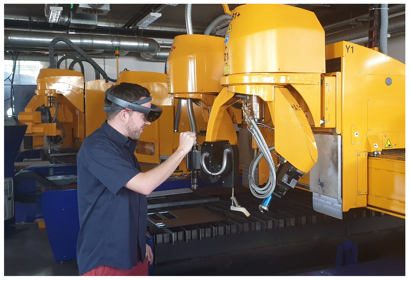
  • Slovak manufacturer of advanced cutting machines
    The use of augmented or mixed reality for the maintenance and operation of complex machines, the area of which reaches several tens of meters, is currently also an open topic, which requires a comprehensive multidisciplinary approach. International leaders in cutting technologies have already begun to implement such solutions. Therefore, a discussion about the possibilities of implementing maintenance and diagnostic systems using extended reality also took place with a Slovak company in this area (Figure 2).
  • Control of sophisticated industrial devices with limited access
    Another of the industrial partners demanded the use of augmented or mixed reality in the control and diagnostics of various sophisticated devices, to which only a limited group of employees have access. This eliminates the need to implement physical control panels, to which even a regular employee can have access. The requirement is that the device can be controlled only by an employee who has access to a mobile device (smartphone/tablet) with an augmented or mixed reality application. In addition to security, such an application also brings the advantages described in the previous points.

1.2. Related Research

In the analysis of the state-of-the-art of the solved problem, we focused on searching scientific works and existing solutions in the subject field. The found projects showed the possibilities of using augmented or mixed reality for control and monitoring of mechatronic systems within the IoT networks. Another important aspect considered was whether a project was developed using open source code, and whether it was put into practice.
References [14,15] refer about the use of standard communication protocols, which should be used in the design of an IoT system with the implementation of web standards. This creates the so-called Web of Things. Web of Things is designed for easy integration of systems into the current web. It is therefore an idea to create a common application level for IoT based on web technologies and protocols. Subsequently, this idea was extended in Reference [16] by the term Augmented Worlds. The Augmented World concept can be defined as a software application that adds digital objects to the surrounding physical environment (e.g., city, building, room) that users or software agents can interact with. The combination of Web of Things and Augmented World created the concept of Web of Augmented Things.
The concept of Augmented Things was presented in Reference [17]. The idea is to create a database of digital copies of real objects (typically it can be consumer electronics) and assign various information to them. This can be, for example, maintenance information, instructions for use, and so forth. After capturing a real object (its digital copy is in the database of Augmented Things), information about this real object will be displayed on mobile device’s screen in the augmented reality.
Close to the focus of the research is the concept of the author Phillipe Lewicki [18]. He created a demonstration application that could be used to control a Phillips Hue smart light bulb using a Microsoft HoloLens headset. With the help of HoloLens, it was possible to select the color of the light of a given bulb with a simple gesture in augmented/mixed reality. The author realized that today’s solutions allow you to control light bulbs through a mobile application. In them, it is then necessary to find a specific room and a light bulb that he wants to control. This may not always be practical, and control with a headset provides greater convenience. However, the described concept has not been further developed.
There is a concept by designer Ian Sterling and engineer Swaroop Pala [19]. This concept demonstrates the control of smart devices using gestures. Microsoft HoloLens is used. The task was to provide a user interface for Android Music Player and an Arduino microcontroller with a connected fan with light. As in the previous case, it is not a complete system, but a single-purpose demonstration application.
The better solution is presented in Reference [20]. The presented AR/MR-IoT framework uses standard and open-source protocols and tools like MQTT (Message Queuing Telemetry Transport), HTTPS (Hypertext Transfer Protocol Secure) or Node-RED. The solution relies on QR codes. The article focuses mainly on the time aspects of communication in the presented framework.
A comprehensive commercial software system for diagnosing and controlling mechatronic systems is Vuforia Studio [21], which was formerly called ThingsWorx Studio. The rebranding took place after the purchase of the library for augmented and mixed reality Vuforia by the technology company PTC. Such an acquisition was a logical step, as PTC reacted very flexibly to the emergence of the Industry 4.0 and Industrial IoT concept. Vuforia Studio uses its closed-source tool, where it is possible to insert 3D and 2D objects, which will be displayed in augmented reality after capturing and recognizing the mechatronic device. This technology does not recognize devices directly, but using its own 2D tags ThingMark, which are actually a conventional technology similar to a QR code. The content is then visualized using Vuforia View.
ŠKODA AUTO has introduced the Smart Maintenance project, which uses augmented reality for maintenance tasks [22]. The Microsoft HoloLens headset is used. It is a relatively simple software application that uses HoloLens cameras to recognize a metal tube with handles. The goal is to diagnose the distances of the handles, which are likely to deviate over time. In the case of a tube detection, the real object is covered by a digital tube with the handles in the right place. Based on the visual information, it is possible to easily identify any displacement and then fix the handle so then it sits with the position of the virtual counterpart. This method of maintenance simplifies and speeds up the work of technicians, as they are relieved of the need to constantly measure the distance. A custom 3D engine was developed for the application. However, after a real test of the application within the solution of Reference [23], it is possible to state that the application reacted badly to the lighting conditions and also suffered from the limitations of the HoloLens headset. The holograms were too pale and did not copy objects correctly. Field of view was limited. The real use of the presented solution is therefore questionable.
Development of methods for control and monitoring of mechatronic systems using new information and communication technologies belongs to modern directions in cybernetics, automation and mechatronics. Based on the analysis of available literature sources and recent research projects it was found out that control and monitoring methods of mechatronic systems connected to IoT using extended reality are implemented in the form of various prototype solutions for selected device types or as closed-source single-purpose application systems. These systems are dedicated and are not easy-to-extend to control and monitor different mechatronic devices without a modification of the client software application. Such systems cannot be considered as generalized and modular solutions. Excursions and discussions with industrial partners have shown that there is interest in such comprehensive solutions. In the context of the ongoing Industry 4.0 industrial revolution, small and medium-sized enterprises are already interested in implementing modern digital technologies such as the Internet of Things, cloud and extended reality, into their manufacturing processes.

2. Materials & Methods

Control and monitoring of mechatronic systems connected in IoT networks using a selected segment of extended reality brings new challenges, as this concept combines hardware and its mechanical parts, microcontrollers and electronic systems, 3D engine for extended reality, mobile devices and communication protocols within the IoT and the cloud. With the proper design of the methodology of control and monitoring of mechatronic IoT systems and the supporting software module, it is possible to synergistically combine the above digital technologies bringing about a functional, original and modular system applicable for a selected class of mechatronic systems.
Nowadays, mechatronic systems in IoT networks are controlled and monitored mainly via industrial panels or console, mobile or web applications. In the case of using such conventional methods of control and monitoring mechatronic systems in a smaller room, this process can be simple and efficient. The list of devices being on one screen, we can set, monitor and control them almost immediately. However, if there are several rooms, buildings or a large digital factory, sorting these items can already be confusing and cumbersome. In these cases, the developed methodology of control and monitoring of mechatronic IoT systems based on augmented reality can yield effective solutions.
Once the system was developed it was important to determine how to recognize and identify the individual mechatronic devices. These devices are subsequently used to anchor computer-generated elements in augmented reality. There are more alternatives [8]:
  • Using a QR Code—The name of the QR code comes from Quick Response, as this code has been developed for quick decoding. It is a two-dimensional bar code printed either on paper or in digital form. Using a mobile device camera we can decode the encoded information. The QR code is a square matrix consisting of square modules. The color of the QR code is black and white. The advantages of using QR codes include the rapid generating of a new QR code for application system build and extension. Next advantage is that each device or sensor can have a unique QR code, so using a QR code we can distinguish the objects with the same shape. The drawback is that we need to keep the mobile device parallel to the code when the recognition process is running, and close enough to the device.
  • Using an image—It is possible to generate augmented or mixed reality using the two-dimensional image. The benefit of this approach is that one image is enough for a single object and it is easy to make images so we do not need any complicated or advanced tools or devices. Only a mobile device is needed for development and use of the application. It is also easy to extend the system. However, there are drawbacks while using the images. Also, as in the case of QR code, we must keep the mobile device close enough to the object when recognizing it, and the mobile device must be parallel to the image, or at the same angle as when making the images. The problem may also be with the same-looking objects not to be distinguished by the application based on the image. It is easier to use QR code for those situations. After researching the creation of an appropriate image, we find that the image has to satisfy certain properties. The image size (width and height) should range from 500 to 1000 pixels. The image can not include patterns of repetition, low texture and low contrast. The image color can be tricky because the computer sees the image in shades of gray. With this technology, colors which can be differentiated very well by the human eye, can be almost the same for computer. The textured portion layout must be uniform, contain only little text, and the white portion must be kept as small as possible.
  • Using a three-dimensional (3D) model—An interesting option is a creation of 3D map based on 3D objects. This approach is very similar to that used above. An application based on the device’s live camera stream is seeking conformity with the model that was created. This approach has the advantage of being able to locate the target object from a greater distance and from any angle. In addition, the mobile application does not lose as easily found an object as in the case of the previous two approaches. The drawback is that creating of 3D map is a complicated and lengthy task, which may also reduce the ease of scalability of the application system. In practice, image recognition is usually done using convolutional neural networks [24]. At present, convolutional neural networks are also used in natural language processing research and other areas of computational intelligence [25].
After considering the advantages and disadvantages of the above alternatives, we decided to use a 3D model. Although creating and extending the system is more time-consuming, smooth running and more intuitive application design was more important to our case. The use of a three-dimensional model and a three-dimensional map is original in the issue of monitoring and control of mechatronic systems using augmented reality and is one of the benefits of the proposed solution.
Based on the analysis, a concept of the application system is proposed, which is shown in Figure 3.
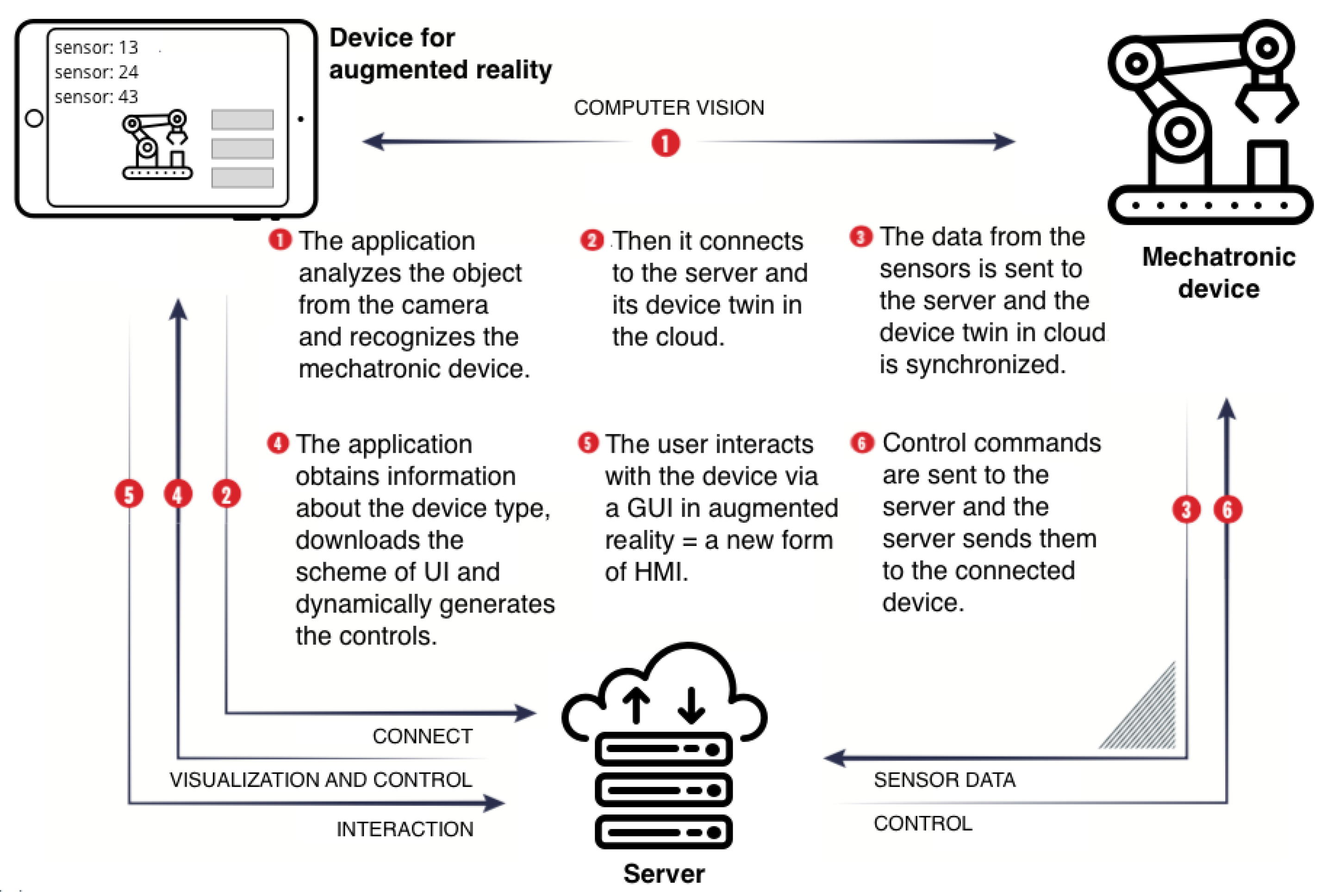
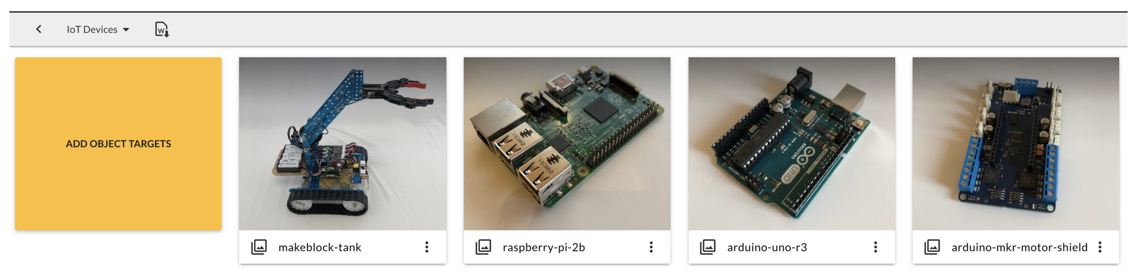
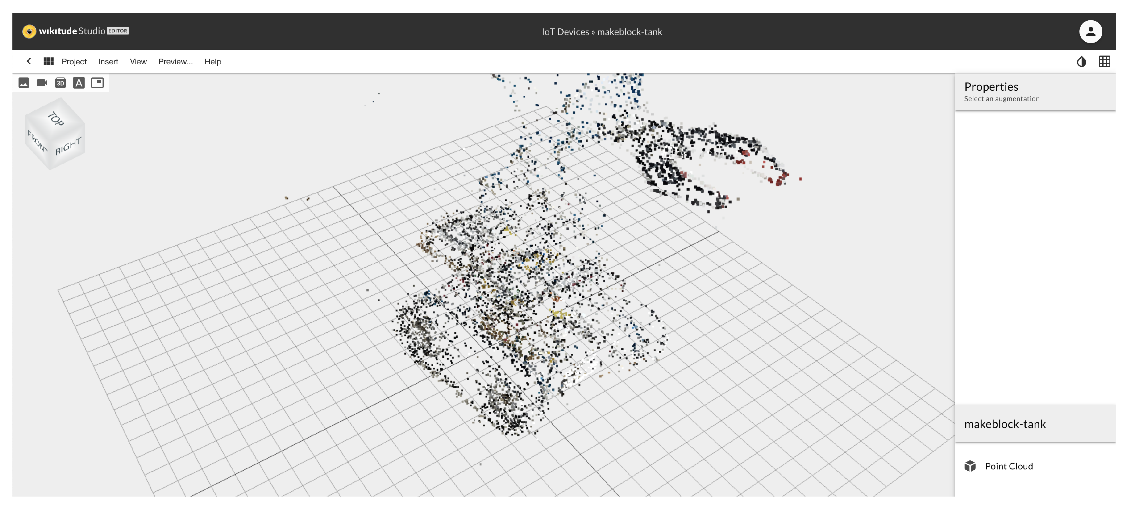
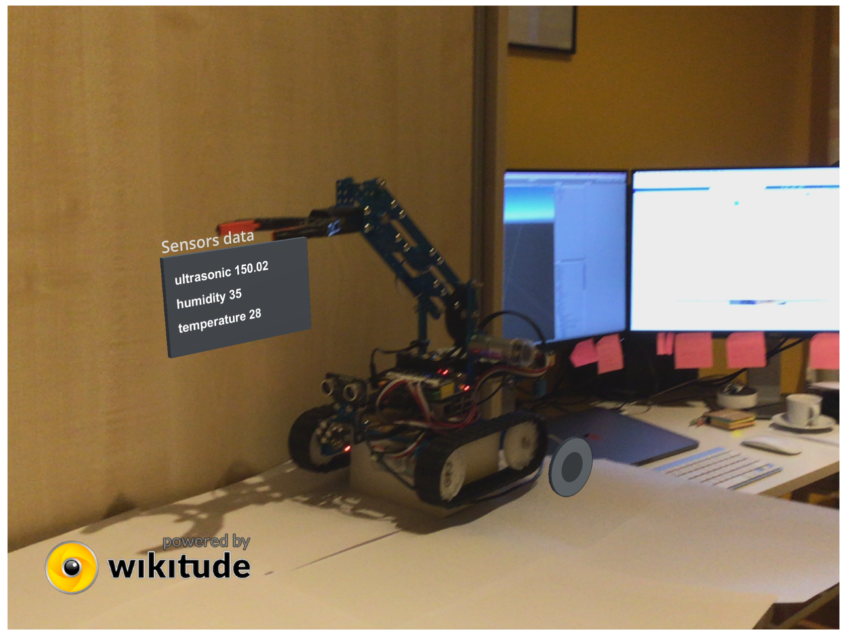
  • The software application analyzes the image from the camera of the mobile device and recognizes the mechatronic system
    The augmented reality mobile app recognizes a real mechatronic device using a camera and a 3D map created in the Wikitude Studio [26]. The 3D map of the mechatronic device is created using photographs of the device taken from several angles. Subsequently, the Wikitude SDK (software development kit) augmented and mixed reality library can interpret this 3D map from a database. The database is stored in a software application on an Apple iPad tablet. The advantage of this method is the ability to recognize the object from any angle. Consequently, even with less visibility tracking does not have to be interrupted as Wikitude can also store also close surroundings of the object. Thus, the implementation of the proposed solution can do without conventional methods of recognizing objects relying on QR codes.
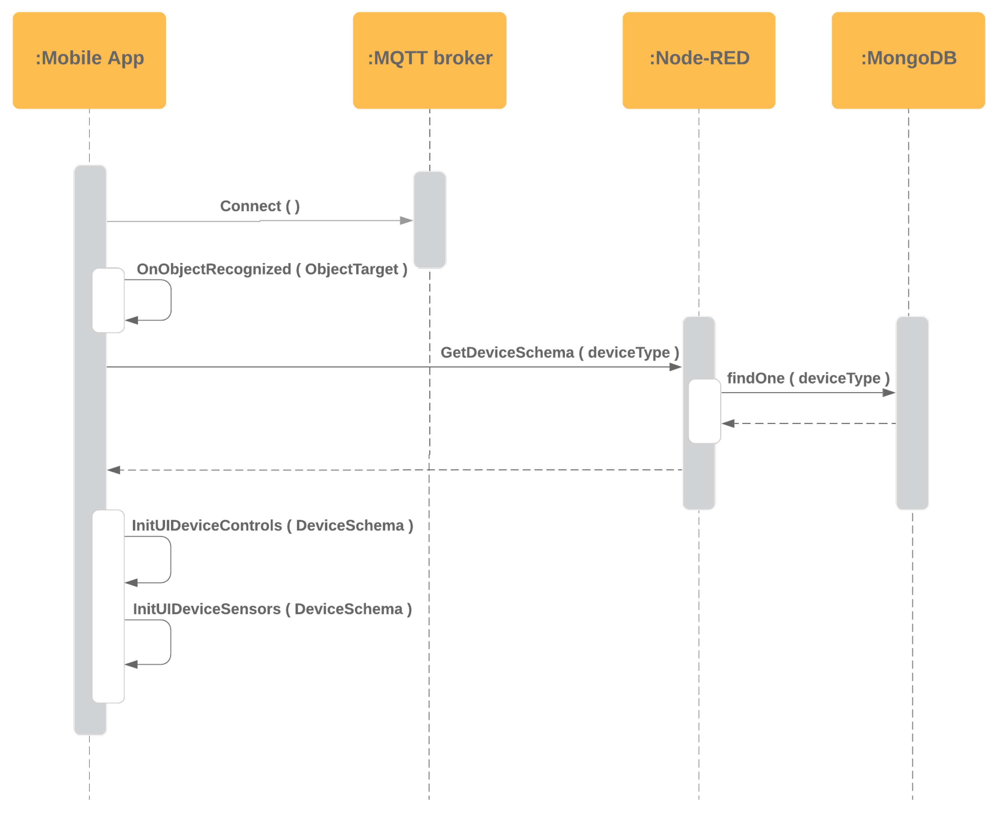
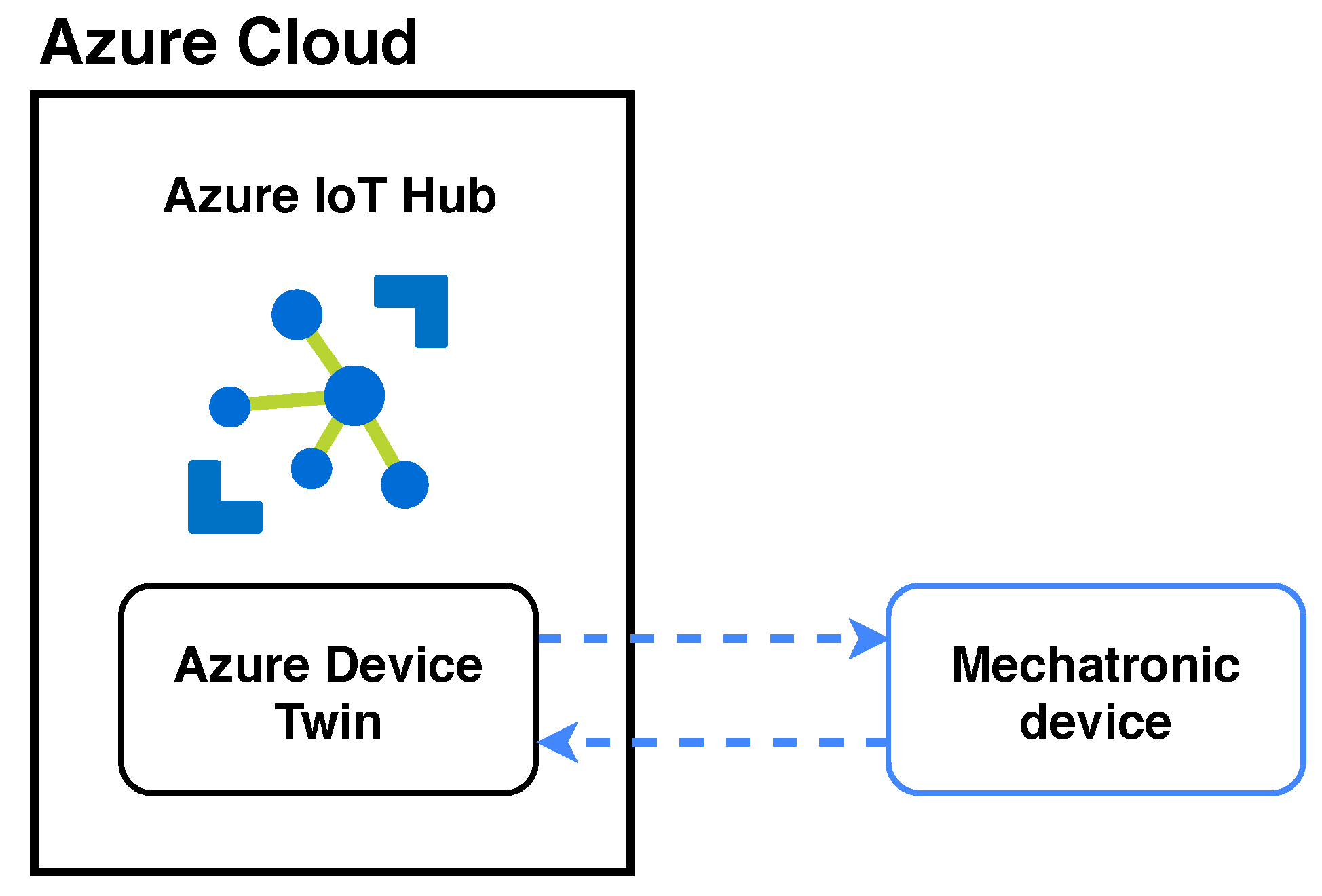
  • The mobile device connects to the server and the mechatronic system’s device twin in the cloud
    The mobile device is connected to the cloud where the recognized mechatronic system has its digital copy (device twin).
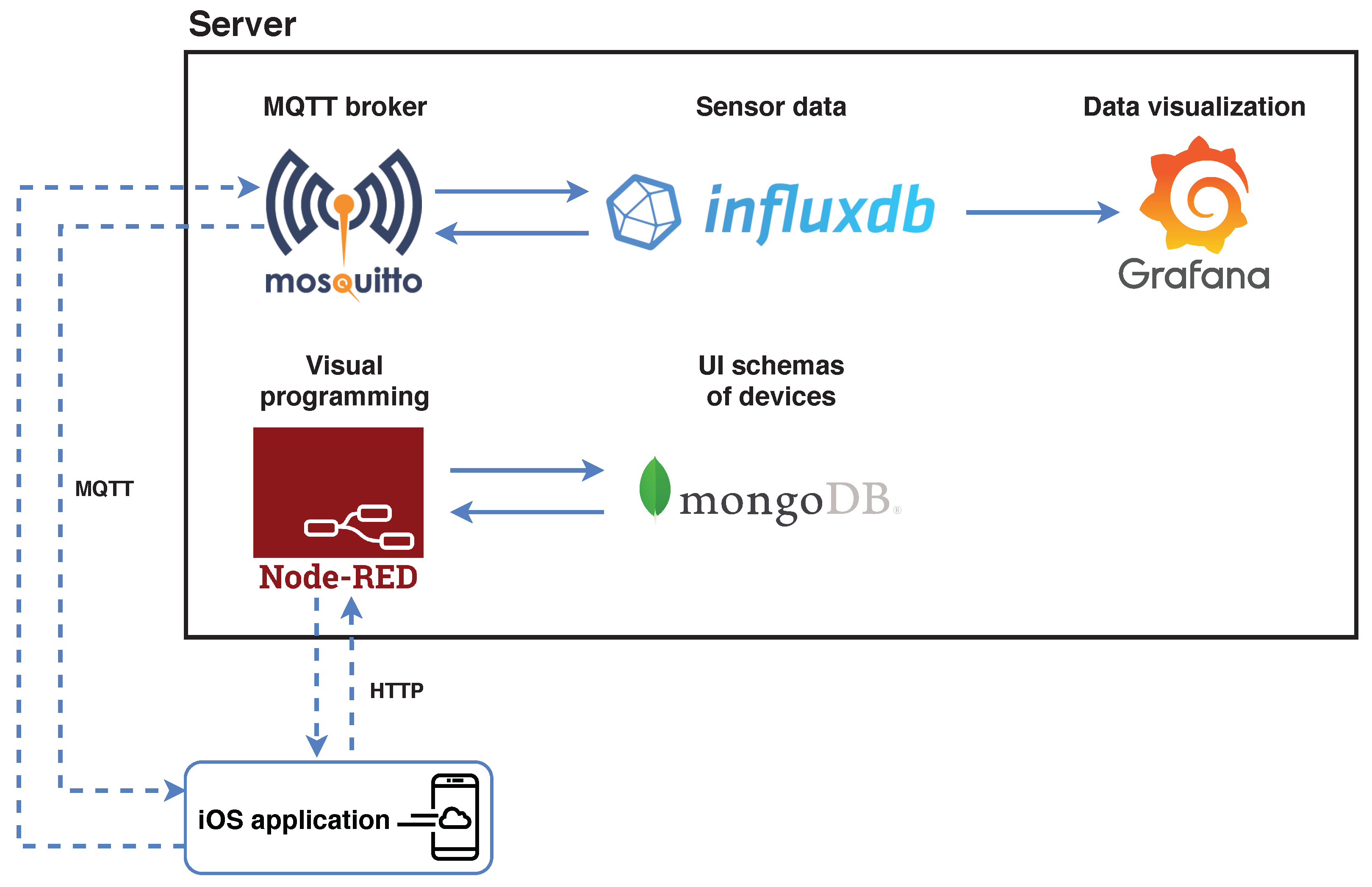
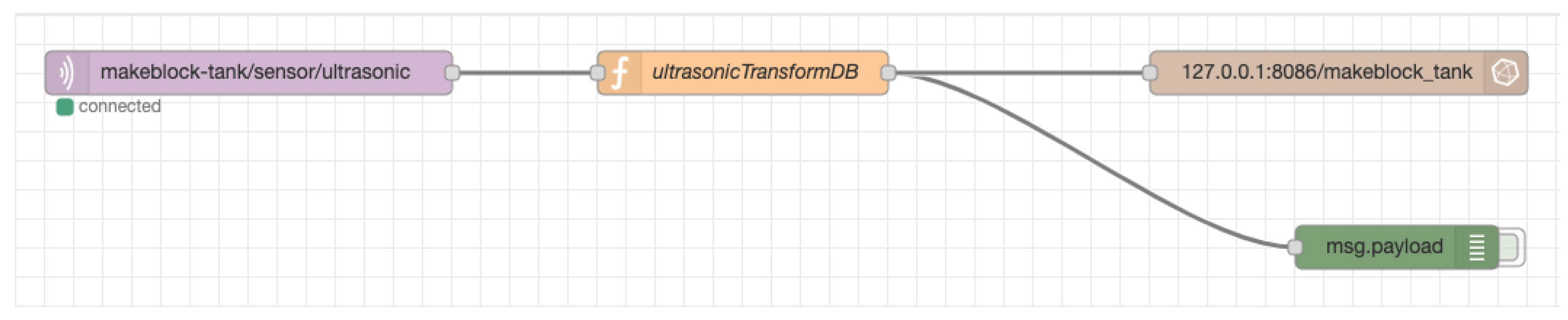
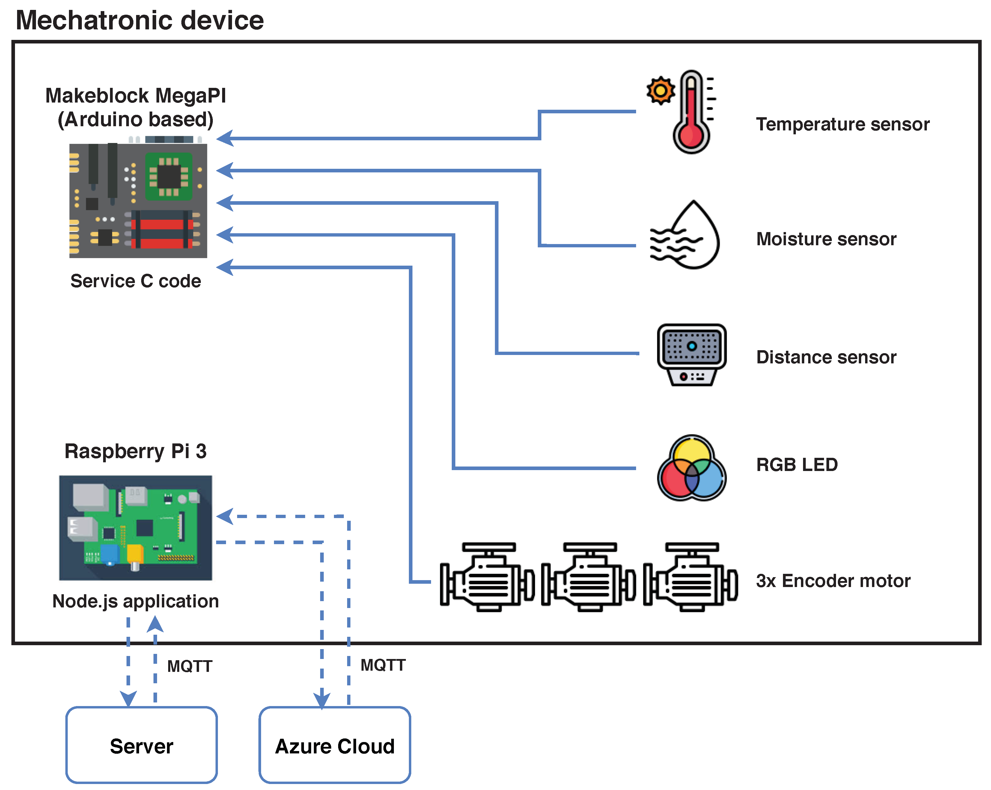
  • The data from sensors of the mechatronic device is sent to the server, and the device twin in the cloud is synchronized
    The mechatronic device automatically sends data under its identifier from sensors to the server where the data is also stored. For this purpose, the InfluxDB database is used [27], designed for time-dependent data which can then be visualized in the Grafana environment [28]. At the same time, the digital copy of the mechatronic device is synchronized at the level of the Microsoft Azure Device Twin, which ensures the visibility of current data even in the cloud environment [29].
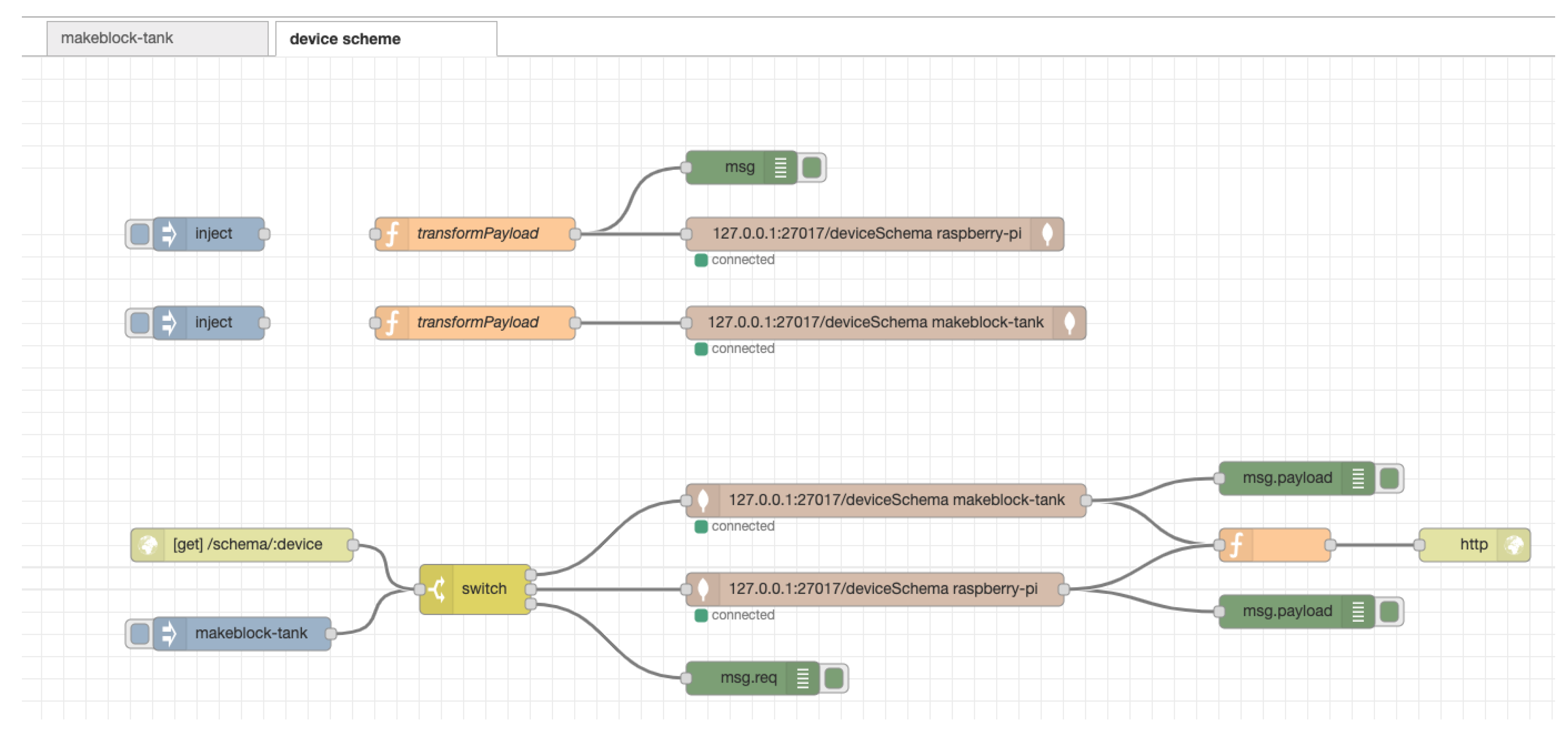
  • The application obtains information about the type of the mechatronic device, downloads the definition of the user interface and draws a graphical interface for control and monitoring of the system
    The proposed system works in such a way that the mobile application recognizes the mechatronic device and—according to its identifier- obtains a unique definition scheme of the user interface for the needs of its monitoring and control. The concept of definition schemes for a dynamic generation of a graphical user interface in augmented reality is one of the pillars of modularity of the implemented solution and at the same time one of the application benefits. The mobile application has access to these definition schemes due to the connection to the database. The connection is realized by means of visual flow-based programming in the Node-RED environment [30], where a suitable scheme is obtained based on the parameter.
  • The user interacts with the mechatronic device through a graphical interface in the augmented reality—a new form of HMI
    Based on a unique definition scheme, the mobile application displays a graphical user interface in augmented reality consisting of two parts. The first part is diagnostics and displays current data from available sensors. The second part is control and shows the control elements directly designed for the mechatronic device. Subsequently, the user is allowed to interact with the mechatronic device through a graphical interface in augmented reality, which is one of the new modern forms of human-machine interface (HMI).
  • Control commands are sent to the server which sends them to the connected mechatronic device
    Control commands are sent from the mobile device to the server using the MQTT communication protocol. On the server, they are processed and executed. The software application on the mechatronic device listens on the MQTT topic and subsequently sends these requests to sensors and actuators via serial communication.
To achieve the set objectives, it is necessary to design and implement a comprehensive hardware-software system for control and monitoring of mechatronic IoT systems based on the augmented reality and the concept of definition schemes for dynamic generation of graphical user interface. The developed system will be tested on a laboratory mechatronic system connected to the IoT.

3. Results

The development of such a complex system had to be done in cooperation with other workers and in several parallel lines to cover all four component parts of mechatronics (mechanics, electronics, automation and information-communication technologies). In what follows, the the whole system will be described using the description of its individual parts: server, augmented reality mobile device (Apple iPad), laboratory mechatronic device and cloud Microsoft Azure.

3.1. Server

The tools, which are implemented on the server side (Figure 4) in the described project, can be run on practically any Linux-based operating system. In the developed solution, Raspberry Pi 3 microcomputer and Raspbian operating system were used as a server. It is based on the Debian distribution with an emphasis on optimization for this type of microcomputer.
The MQTT broker (mosquitto) runs on the server and serves as the main central point through which all communication between the mobile device and the currently recognized mechatronic system takes place. Messages are sent to the broker using publish-subscribe communication on undefined topics. It is therefore not necessary to define them in advance, but the application that wants to obtain data from the address must be subscribed to receive this type of message.

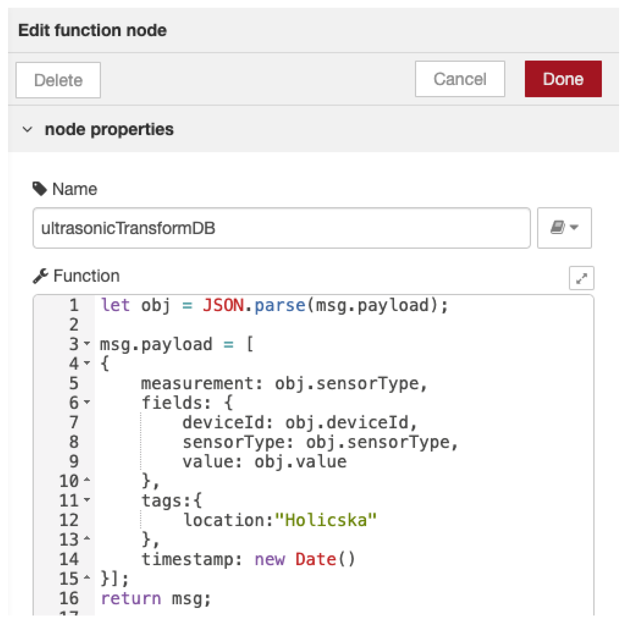
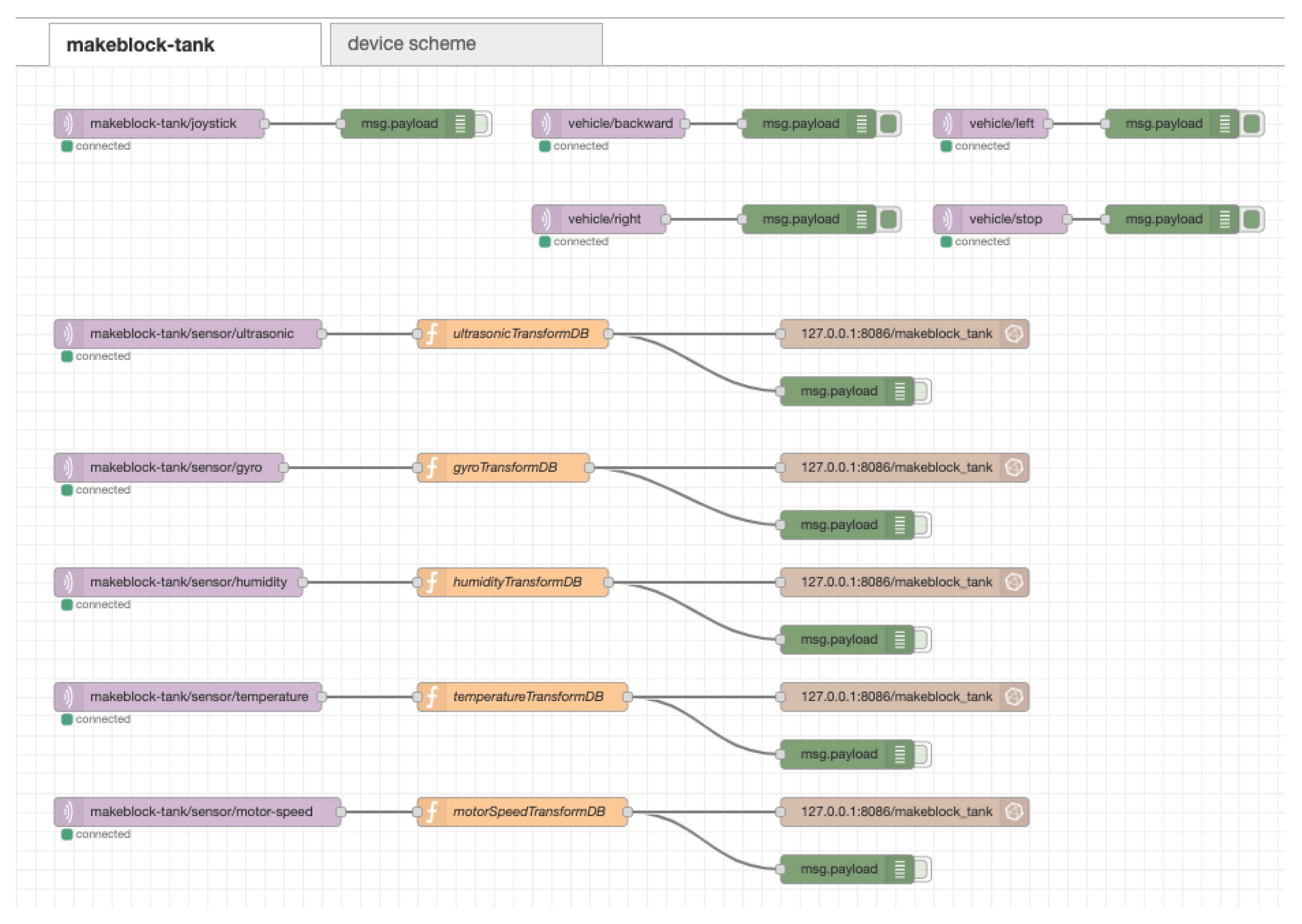
3.1.1. Flow-Based Programming of Communication Interface Using Node-RED

Node-RED consists of a runtime based on Node.js and a visual editor. The program is created in the browser by dragging functional nodes from the palette into the workspace. Then it is necessary to interconnect these nodes. The application is then deployed to production automatically using the deploy button. Additional nodes can be easily added by installing new nodes created by the programming community. Flows that are created in the workspace can be exported and shared as JSON (JavaScript Object Notation) files.
First, connection to a local MQTT broker is required. Additional settings, such as login details or additional messages for connections, can also be filled in within the settings. In this case, however, we can do with the IP address 127.0.0.1 and the port 1883.
When we have the connection to the MQTT broker implemented, we can use this broker as an I/O (input/output) node. In Figure 5, there is an input MQTT node connected to a local MQTT broker and subscribed to incoming messages from makeblock-tank/sensor/ultrasonic topic. This is followed by the transformation function ultrasonicTransformDB (Figure 6), which ensures the transformation of the incoming message into the required format. When editing a block of this type, it is possible to insert classic JavaScript code. This transformation function is performed whenever a message arrives at a given topic. First, the body of the message that came from the mechatronic system is obtained, and then a new object is prepared in the already required format, which is suitable for storage in the database. Said type of coupling is created for all available sensors within one mechatronic system.
In Figure 7 it is possible to see the flow in Node-RED (scheme of all interconnected I/O nodes) for mechatronic device Makeblock Tank. Due to the fact that the system is designed with emphasis on modularity, it is possible to add another mechatronic device to the new tab, where the flow for this new device will be located.
In case we would like to add another mechatronic device to the system, then it is necessary to add another flow here. It determines which data should be transformed and in what way, and also, if necessary, in which specific database it should be stored. The stream can also be exported and dynamically loaded into Node-RED using the available API (https://nodered.org/docs/api/) (application programming interface).

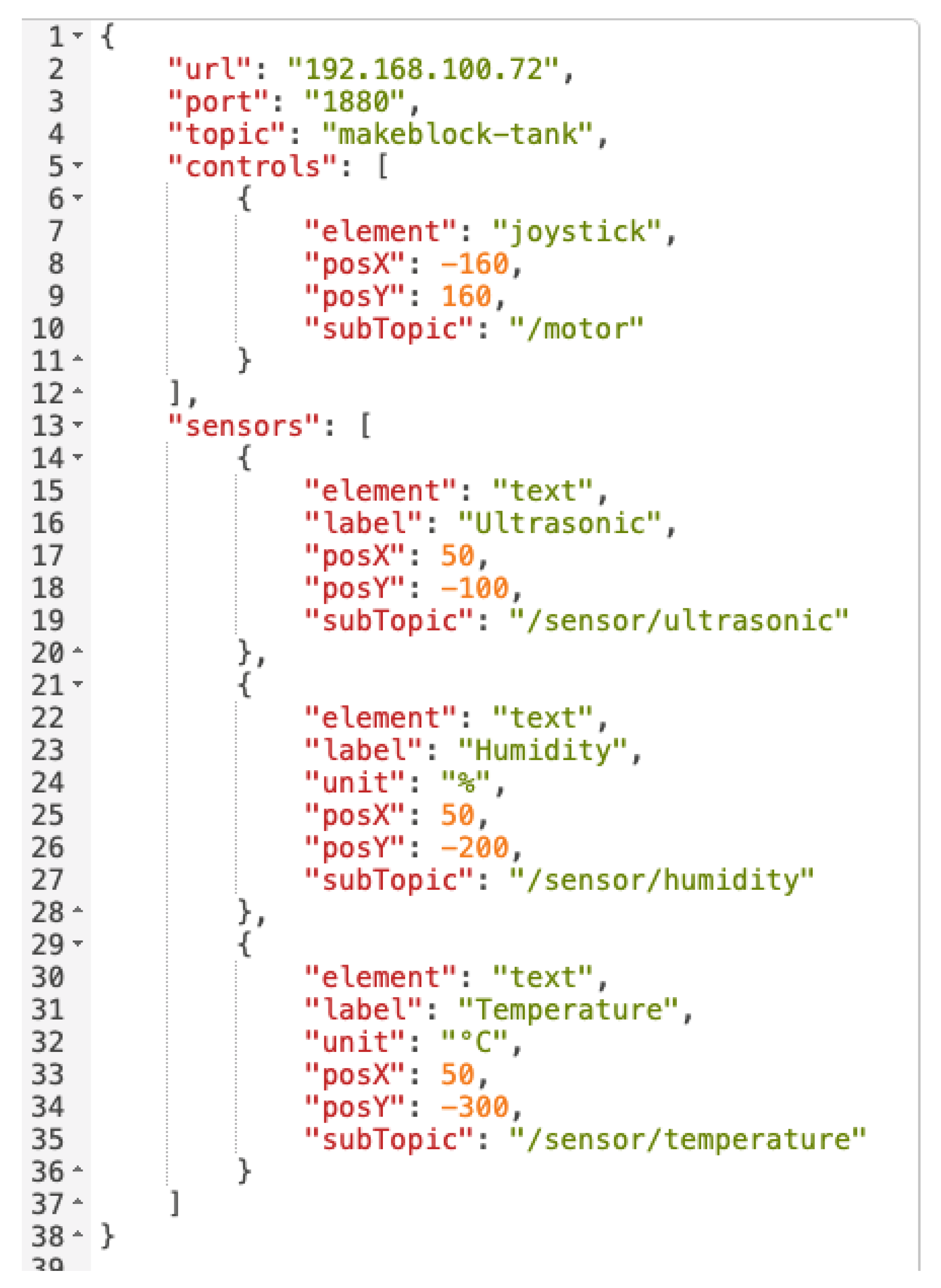
3.1.2. Definition Scheme for Generating a Graphical User Interface

To generate a customizable graphical interface for control and monitoring a mechatronic device in an augmented reality mobile application, it was necessary to design a way for this interface generation to be implemented. The concept of definition schemes for a dynamic generation of the graphical user interface is one of the pillars of modularity of the proposed system for control and monitoring of mechatronic systems using IoT and augmented reality. This is an original concept developed by the authors of the article. The scheme had to be designed with the emphasis on the solution versatility so that it would be applicable also in case of using other display technology than the augmented reality. The format selected was the JSON document as the JSON data format is supported in every relevant programming language. This means that it can be parsed in software applications and it is easy to work with its objects and attributes. In the first part of the scheme, there are the network settings of the master node (MQTT broker), that is, what IP address and port it is located on. These properties are defined at the top of the JSON document as url and port. This is followed by the topic property, which corresponds to the MQTT topic. This unambiguously determines the path of the mechatronic IoT device within the MQTT channel.
In the next part, there are two types of element labels (sensors and controls) in terms of their functionality. Sensors is used for reading elements—for example for data from sensors. Controls is for control elements. Both elements may contain multiple nested GUI (graphical user interface) elements according to the needs of the recognized mechatronic device.
In the current version of the definition scheme, three different GUI elements are available—joystick, button and text. Joystick and button belong to the control elements. They contain these properties):
  • element—element name (joystick, button)
  • label—is optional, as in the case of a joystick it is not necessary and represents the description of the element on the screen
  • posX and posY—determine the generation of the element to the given position, while the elements for control we try to place to the right side of the mechatronic device
  • subTopic—specifies the path for a specific control within the MQTT channel, or the path for the sensor from which the data will be read
The last element is text, which contains the same properties as controls. However, it can also have the unit property, which adds a unit to the read values.
When this JSON document is parsed, it creates a GUI element and then creates a connection to the MQTT broker. The path will then look like this: url:port/topic/subTopic.
In Table 1, there is an overview of elements and their data types for the correct operation of parsing and subsequent generation of a graphical user interface. A question mark for a specific element property indicates that it is optional.
Figure 8 shows the definition scheme for the mechatronic device Makeblock Tank. The scheme is written in JSON format. In the first part, the access data (url, port and topic) are defined, which defines the network access for the given device.
Subsequently, depending on the configuration, the mechatronic device may contain two types of elements on the screen: for read (sensors) and control (controls). The first type is intended only for reading and displaying data from sensors. The controls are those that actively interfere with the device—so they access its actuators.
The specific types of controls and information elements that appear on the screen of a mobile device in augmented reality may be diverse in terms of functionality, so that the system can be expanded in the future. Three types were created for the selected device: joystick, button and text. The first two elements are used to perform the action. The text element is read-only. In the case of this element, there is also the label attribute. With this one, it is possible to add a description—for example the type of a specific sensor.
The displaying control elements also depends on the set position (posX and posY), while the controls are generated from the lower right corner upwards. For reading elements, this is for clarity from the top left corner.
The common attribute for both types is subTopic. It determines the network path where the actuator or sensor is located. If you create the entire path from the url, port, topic, subTopic attributes (e.g., for a joystick), it would look like this: 192.168.100.72:1880/makeblock-tank/motor.
Definition schemes with user interfaces for all available mechatronic devices have their own flow in the Node-RED, where they are connected to the communication. At the top of Figure 9, you can see the inject nodes, which store the current version of the definition schema. When the scheme is changed, it is necessary to activate the node inject, which ensures the sending of the saved definition scheme to the next block. The schema is inserted into the MongoDB database. also shows two different collections—raspberry-pi and makeblock-tank. In each of these collections, there is a diagram for a given device, but its element layout may be different. For example, there could be two mechatronic devices of the type Makeblock Tank, but each has a different identifier and different equipment with sensors and actuators.
The blocks at the bottom of Figure 9 are used to obtain a definition scheme for an application on a mobile device that provides augmented reality. The input is an HTTP GET node that allows to create an HTTP server for requests without having to program it. This node has url set to /schema/:device. The IP address and port of the local server must be specified before this entry. The address also contains the HTTP parameter :device, which represents the name of the mechatronic device (which we want to obtain the definition scheme for). Then the switch node evaluates which device it is and sends requests to the MongoDB database. When using an HTTP node, it is necessary to have an output node of this type. The HTTP output node provides a response for the called service, where the output will be data and HTTP status code. The green nodes are only used to list and check the values in the Node-RED.

3.2. Mobile Device and Augmented Reality Application

The mobile application includes the Wikitude SDK, which provides methods and algorithms for recognizing 3D objects in a real environment using a mobile device camera. A software package in Unity engine format (.unitypackage) is available on the official website of this tool.
Real-world 3D objects are detected by Wikitude by trying to match pre-created references in video streams from mobile device’s camera. Such a prepared reference is called Object Target. It can also be understood as a SLAM map. Object Target is created using input images of a real model (mechatronic device). These are then converted into so-called Wikitude Object Target Collection, which is saved as a .wto file. The procedure for creating a collection is as follows:
  • Creating photos of an object from different angles (up to 30 photos can be inserted)
  • Convert photos to Wikitude Object Target Collection (.wto)
  • Use of the .wto file in the project in the Unity 3D engine
In Figure 10 we can see a list of created Object Targets. Each of the objects contains the Point Cloud, which can be seen in Figure 11. It represents a 3D map which Wikitude uses for recognition of a 3D object. If the user finds Point Cloud insufficient at some angles, it can be expanded with additional photos.

Generating of User Interface Using Definition Scheme

The generation of a dynamic graphical user interface takes place at the Unity engine level via a definition scheme. Its format has been described in the previous text. A sequence diagram describing the method of generating a GUI in the Unity engine is shown in Figure 12.
After launching the mobile application, all necessary libraries are initialized. Each application created in Unity contains void Start () method containing initialization code. First, an asynchronous connection to the MQTT broker is made using the Connect () method. Now the Unity mobile application is ready to recognize mechatronic devices. If the device is recognized, we get its name in the method named OnObjectrecognized (ObjectTarget). This name is sent as an HTTP GET request to the Node-RED using the GetDeviceSchema (deviceType) method, where a connection is established in a separate thread of the mobile application and a schema is obtained. Subsequently, Node-RED starts the programmed flow (Figure 9). The obtained definition scheme with GUI elements is processed in the mobile application using the JSON data format parser and then the methods InitUIDeviceControls(DeviceSchema) and InitUIDeviceSensors (DeviceSchema) are called.
These methods initialize prefabs of native UI elements in the Unity engine. UI element prefab is created in the hierarchy of game objects and all required visual properties are added to it. When this GameObject is set up as needed in the hierarchy, it is necessary to move it to the project structure in the Prefabs folder. This saves the prefab and can then be initialized at any time in the Unity application.
The generation itself works in such a way that the parsed definition schema (parsed JSON) is sent to the InitUIDeviceControls method. It determines which elements are available according to the attributes of the object. Depending on the element, it is possible to initialize a prefab named button or joystick.
During initialization, it is necessary to insert the generated object also on the canvas, which renders the UI objects. Otherwise, they would not appear in the mobile application.
According to the sequence diagram (Figure 12) it is clear how the whole process works in the mobile application. The mobile device is aimed by the user at a mechatronic device/object that the application can recognize. After the whole process of device recognition, obtaining the necessary definition schemes and data, the GUI is displayed, as can be seen in Figure 13. The control part of UI was in terms of user experience situated to the right part of the generated GUI on the mechatronic device. In the lower right part, we can use the thumb in a simple way. In the described case of the Makeblock Tank device, only the joystick is needed, which is used to control the belts and thus the movement of the device. Elements such as sensor data that does not need to be clicked are visualized in augmented reality at the top of the device.

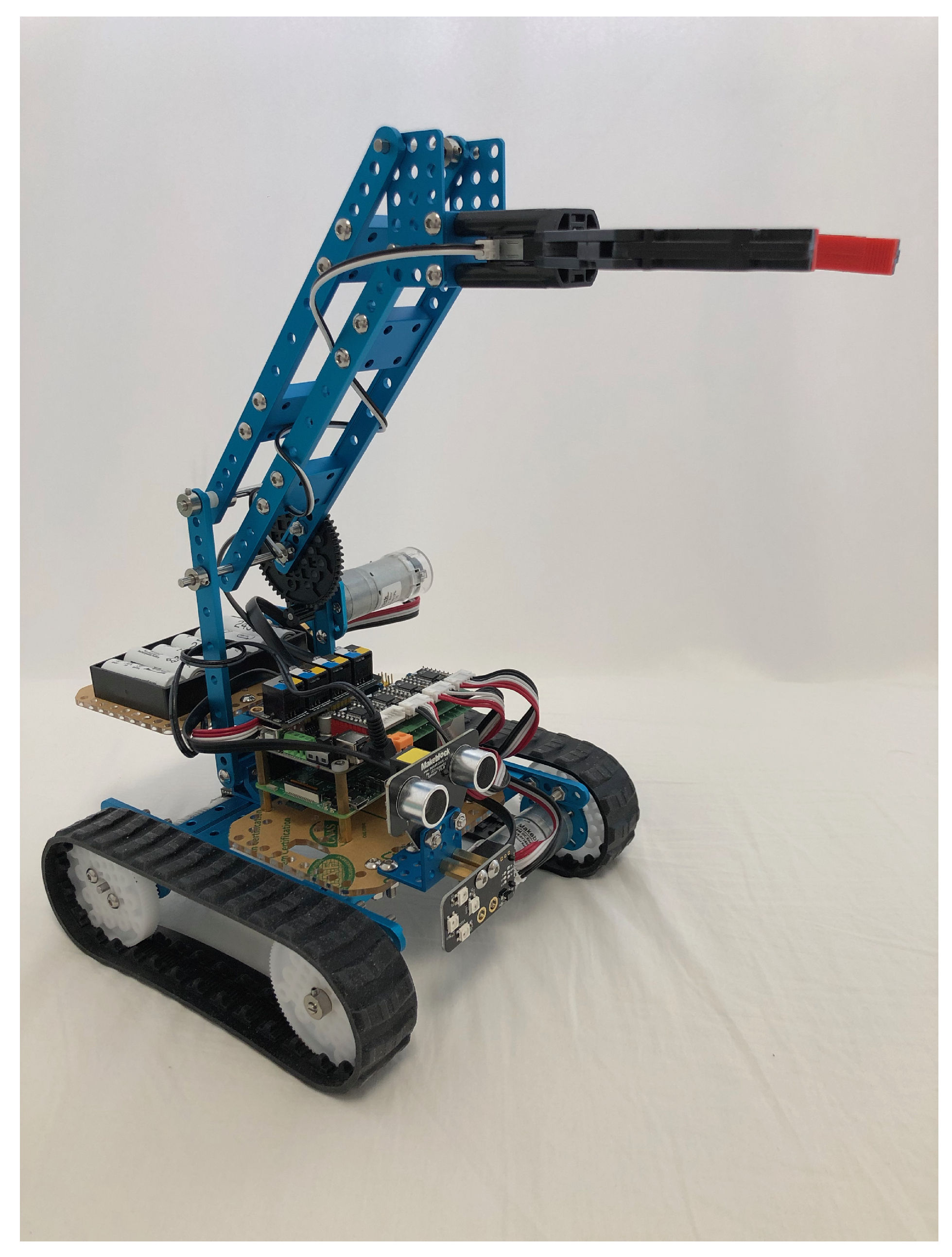
3.3. Laboratory Mechatronic Device

To implement and verify the method of monitoring and control of mechatronic systems using IoT and augmented reality, it was necessary to build a suitable laboratory physical model. For this purpose, the mechatronic kit Makeblock Ultimate 2 was selected. The Robotic Arm Tank model was built, which best met the requirements for testing and demonstration of the developed software system. A diagram of the laboratory model showing the connected electronic systems, sensors and actuators can be seen in Figure 14.
The main electronic element of the laboratory model is the Makeblock MegaPi development board, which is built on the Arduino MEGA 2560 platform, while supporting programming using the Arduino IDE. The development board contains three ports for connecting motors with an encoder. Sensors for measuring the distance of the vehicle from the obstacle (ultrasonic sensor) and a humidity/temperature sensor were connected. RGB LED (Light-Emitting Diode) was connected as another actuator.
A key element of the laboratory mechatronic system is its wireless control. The package contained a bluetooth communication module, which was not suitable as it was designed to control a device with a ready-made application from Makeblock. So another alternative was chosen—the connection of MegaPi with a Raspberry Pi 3 microcomputer, which has a built-in WiFi module. The MegaPi is ready for connection to the Raspberry Pi, as it has three screw holes in the same places as the Raspberry Pi 3. It also allows serial communication with this microcomputer.
Laboratory mechatronic device Makeblock Robotic Arm Tank can be seen in Figure 15.
After assembling the laboratory mechatronic system, MegaPi had to be programmed. The mBlock tool is available for teaching programming. However, in the described solution, it is necessary to have the complete MegaPi functionality available and to access the device control using the API interface. This is suitable to implement via the Arduino IDE, where the complete service code is loaded to access all sensors and actuators that Makeblock can work with. It is then possible to access the sensors and actuators by calling the API interface, specifically in our case by sending parameters from the Raspberry Pi via a serial line. These parameters can be sent, for example, using a library in JavaScript or Python. In our case we use JavaScript.
Before using the library, it is necessary to upload the service code to the MegaPi microcontroller via the Arduino IDE. This means that it is no longer necessary to program all the functionalities for actuators and sensors manually, but we are making available an interface for higher programming languages, as it was mentioned.
MegaPi is physically connected to the Raspberry Pi 3 and the service code is loaded at the same time, the next step is to install the MegaPi control library. It can be done using the Node Package Manager (NPM) and the npm install megapi command. During development, it was found that this interface is not sufficiently maintained and some methods are no longer functional. It was therefore necessary to study how the communication works from publicly available source code. Subsequently, it was necessary to make adjustments to the service source code as well as the JavasScript library code.
At the beginning of the JavaScript program, the MegaPi constructor is called, where two parameters are required:
  • serial communication access path
  • the body of the function to be executed after initialization
Subsequently, it is possible to call functions for access to ports and sensors. All functions are described on GitHub (https://github.com/Makeblock-official/NodeForMegaPi).

3.4. Device Twin in Azure Cloud

The system design assumes the synchronization (Figure 16) of current data from the sensors of the mechatronic system to the cloud using device twin. This technology is available as part of the Microsoft Azure IoT Hub and is created for each added mechatronic device.
Azure IoT Hub is a managed service that runs in the Microsoft Azure cloud. It serves as a central point for two-way communication between IoT applications and IoT devices. Azure IoT Hub can be used to create Internet of Things solutions with reliable and secure communication between the cloud-based backend and millions of IoT devices. It is possible to connect virtually any device to it.
Device twins are JSON documents that store information about the state of an IoT device, including configurations, metadata, and conditions. The Azure IoT Hub maintains such a device twin for each IoT device that is connected to the IoT Hub [31].

4. Conclusions

The article deals with a modern form of control and monitoring of mechatronic systems connected within the Internet of Things networks using augmented reality.
Based on the analysis of available literature sources and recent research projects, it was found that methods for control and monitoring of mechatronic systems connected within IoT using extended reality are implemented in the form of various prototype solutions for dedicated devices or as closed-source single-purpose application systems; such systems are not complete and without a modification of the client software application it is not feasible to easily extend the control and monitoring also for different mechatronic devices. Such solutions cannot be considered as generalized and modular ones. Excursions and discussions with industrial partners have shown that there is a growing interest in such comprehensive solutions. In the context of the ongoing Industry 4.0 industrial revolution, small and medium-sized enterprises are already interested in the implementation of modern digital technologies such as the Internet of Things, cloud and extended reality, into their manufacturing processes.
The result of the proposed research is a modular program system with a new form of human-machine interface (HMI) implemented in augmented reality. The graphical user interface uses a new concept of definition schemes for its dynamic generation. In the proposed solution, modern detection and recognition methods of 3D objects in the augmented reality are used instead of conventional methods of control and monitoring of mechatronic IoT systems based on scanning QR codes.
The scientific and application contributions can be summarized in the following points:
  • Design of a modern form of control and monitoring of mechatronic systems using the Internet of Things and augmented reality.
  • Implementation of an application system for control and monitoring of mechatronic systems connected to the Internet of Things with a new form of human-machine interface based on detection and recognition of 3D objects.
  • Design and implementation of the concept of definition schemes for dynamic generation of a graphical user interface for control and monitoring of mechatronic systems.
  • Verification of the designed and implemented application system on a laboratory mechatronic system.
An important result of this part of the presented work is the design and development of an application platform of a modular solution with a modern HMI form in augmented reality. The proposed solution complements and improves conventional augmented reality-based methods of control and monitoring of mechatronic IoT systems (relying on QR code scanning). The new application platform represents an original approach based on modern software for detecting and recognizing 3D objects. The generalizability and modularity of the developed solution is supported by the original concept of definition schemes for dynamic generation of a graphical user interface in augmented reality.
It turned out that the Wikitude SDK is sufficiently robust and advanced to scan the mechatronic device even in different lighting conditions though this was not the primary aim of this research.
In the discussion [32], a situation is addressed when it was necessary to recognize marks and objects under very low light conditions (less than 10 LUX). The Wikitude SDK can handle this situation as well. Wikitude is able to recognize objects with a high success [33] even if there are low light, shades, reflections or noisy surroundings in the environment.
If the lighting conditions are very low, it is possible to use the Input Plugins API [34] as suggested in the discussion in Reference [32]. It works so that the input image is preprocessed using for example, the OpenCV library. The resulting image is further processed by Wikitude and evaluated in the real time. In such a case, it is possible to obtain a very acceptable recognition of marks and objects as can be seen in the video in Reference [35].
Possible limitations of the presented system result from the fact that in a digital factory there can be several devices with a similar shape or devices with large dimensions. In this case, it would be possible to use own 3D identifiers, unique for each machine. However, such identifiers are difficult to copy with sufficient accuracy only using a set of photographs. The 3D identifiers open up new ways and opportunities for future research and development of optimal shapes, dimensions and algorithms for generating them using generative modeling. It is expected that 3D identifiers will be produced using the 3D printing technology which allows to create and test identifiers of different shapes and dimensions without the need to manufacture expensive conventional molds for plastic castings.
Scientific and application contribution to the field of Internet of Things and extended reality as declared in the four above points consists in the developed original solution generalizable and modifiable for further research and technical practice in Industry 4.0.

5. Patents

Proposed “Method for monitoring and control of mechatronic systems using augmented reality” is patent pending under application number 158-2019 in Industrial Property Office of the Slovak Republic [https://wbr.indprop.gov.sk/WebRegistre/Patent/Detail/158-2019].

Author Contributions

E.S. and E.K. proposed the idea in this paper and prepared the software application; O.H., P.D. and R.L. designed the experiments, E.S. and E.K. performed the experiments; O.H., and R.K. analyzed the data; E.K. wrote the paper; E.S., O.H., P.D. and R.L. edited and reviewed the paper. All authors have read and agreed to the published version of the manuscript.

Funding

This work has been supported by the Cultural and Educational Grant Agency of the Ministry of Education, Science, Research and Sport of the Slovak Republic, KEGA 038STU-4/2018 and KEGA 016STU-4/2020, by the Slovak Research and Development Agency APVV-17-0190, and by the Tatra banka Foundation within the grant programme Quality of Education, project No. 2019vs056 (Virtual Training of Production Operators in Industry 4.0).

Conflicts of Interest

The authors declare no conflict of interest.

References

  1. Kozák, Š; Ružický, E.; Štefanovič, J.; Schindler, F. Research and education for industry 4.0: Present development. In Proceedings of the 2018 Cybernetics & Informatics (K & I), Lazy pod Makytou, Slovakia, 31 January–3 February 2018; pp. 1–8. [Google Scholar] [CrossRef]
  2. Wolniak, R.; Saniuk, S.; Grabowska, S.; Gajdzik, B. Identification of Energy Efficiency Trends in the Context of the Development of Industry 4.0 Using the Polish Steel Sector as an Example. Energies 2020, 13, 2867. [Google Scholar] [CrossRef]
  3. Lin, Y.-C.; Yeh, C.-C.; Chen, W.-H.; Hsu, K.-Y. Implementation Criteria for Intelligent Systems in Motor Production Line Process Management. Processes 2020, 8, 537. [Google Scholar] [CrossRef]
  4. Dobrowolska, M.; Knop, L. Fit to Work in the Business Models of the Industry 4.0 Age. Sustainability 2020, 12, 4854. [Google Scholar] [CrossRef]
  5. Kościelniak, H.; Łęgowik-Małolepsza, M.; Łęgowik-Świącik, S. The Application of Information Technologies in Consideration of Augmented Reality and Lean Management of Enterprises in the Light of Sustainable Development. Sustainability 2019, 11, 2157. [Google Scholar] [CrossRef] [Green Version]
  6. The Foundry. VR? AR? MR? Sorry, I’M Confused. Available online: https://www.foundry.com/insights/vr-ar-mr/vr-mr-ar-confused (accessed on 16 June 2020).
  7. Sánchez-Herrera-Baeza, P.; Cano-de-la-Cuerda, R.; Oña-Simbaña, E.D.; Palacios-Ceña, D.; Pérez-Corrales, J.; Cuenca-Zaldivar, J.N.; Gueita-Rodriguez, J.; Balaguer-Bernaldo de Quirós, C.; Jardón-Huete, A.; Cuesta-Gomez, A. The Impact of a Novel Immersive Virtual Reality Technology Associated with Serious Games in Parkinson’s Disease Patients on Upper Limb Rehabilitation: A Mixed Methods Intervention Study. Sensors 2020, 20, 2168. [Google Scholar] [CrossRef] [PubMed] [Green Version]
  8. Bucsai, S.; Kučera, E.; Haffner, O.; Drahoš, P. Control and Monitoring of IoT Devices Using Mixed Reality Developed by Unity Engine. In Proceedings of the 2020 Cybernetics & Informatics (K & I), Velke Karlovice, Czech Republic, 29 January–1 February 2020; pp. 1–8. [Google Scholar] [CrossRef]
  9. Milgram, P.; Kishino, F. A taxonomy of mixed reality visual displays. IEICE Trans. Inf. Syst. 1994, 77, 1321–1329. [Google Scholar]
  10. Salamone, F.; Belussi, L.; Danza, L.; Galanos, T.; Ghellere, M.; Meroni, I. Design and Development of a Nearable Wireless System to Control Indoor Air Quality and Indoor Lighting Quality. Sensors 2017, 17, 1021. [Google Scholar] [CrossRef] [PubMed]
  11. Geng, Z.; Chen, N.; Han, Y.; Ma, B. An improved intelligent earlywarning method based on MWSPCA and itsapplication in complex chemical processes. Can. J. Chem. Eng. 2020, 98, 1307–1318. [Google Scholar] [CrossRef]
  12. Minchala, L.I.; Peralta, J.; Mata-Quevedo, P.; Rojas, J. An Approach to Industrial Automation Based on Low-Cost Embedded Platforms and Open Software. Appl. Sci. 2020, 10, 4696. [Google Scholar] [CrossRef]
  13. Erasmus, J.; Vanderfeesten, I.; Traganos, K.; Keulen, R.; Grefen, P. The HORSE Project: The Application of Business Process Management for Flexibility in Smart Manufacturing. Appl. Sci. 2020, 10, 4145. [Google Scholar] [CrossRef]
  14. Trifa, V.; Guinard, D.; Carrera, D. Web Thing Model. Available online: http://model.webofthings.io/ (accessed on 16 June 2020).
  15. Guinard, D.; Trifa, V.; Pham, T.; Liechti, O. Towards physical mashups in the web of things. In Proceedings of the 2009 Sixth International Conference on Networked Sensing Systems (INSS), Pittsburgh, PA, USA, 17–19 June 2009; pp. 1–4. [Google Scholar]
  16. Croatti, A.; Ricci, A. Towards the web of augmented things. In Proceedings of the 2017 IEEE International Conference on Software Architecture Workshops (ICSAW), Gothenburg, Sweden, 5–7 April 2017; pp. 80–87. [Google Scholar]
  17. Rambach, J.; Pagani, A.; Stricker, D.; Aleksy, M.; Schmitt, J.; Langfinger, M.; Schneider, M.; Schotten, H.; Malignaggi, A.; Ko, M. Augmented things: Enhancing AR applications leveraging the Internet of Things and universal 3d object tracking. In Proceedings of the IEEE International Conference on Industrial Technology (ICIT), Nantes, France, 9–13 October 2017; Volume 22, p. 25. [Google Scholar]
  18. Lewicki, P. Controlling Lights with the Hololens and Internet of Things. Available online: http://blog.htmlfusion.com/controlling-lights-with-the-hololens-and-internet-of-thingsatch-one-of-philippes-appearances-in-june/ (accessed on 1 June 2020).
  19. Sterlink, I.; Swaroop, P. Control with Your Smart Devices by Staring and Gesturing. Available online: https://blog.arduino.cc/2016/07/26/control-with-your-smart-devices-by-staring-and-gesturing/ (accessed on 16 June 2020).
  20. Blanco-Novoa, Ó.; Fraga-Lamas, P.; A Vilar-Montesinos, M.; Fernández-Caramés, T.M. Creating the Internet of Augmented Things: An Open-Source Framework to Make IoT Devices and Augmented and Mixed Reality Systems Talk to Each Other. Sensors 2020, 20, 3328. [Google Scholar] [CrossRef] [PubMed]
  21. Gallash, A. Thingworx–plattform zur integration herausfordernder anforderungen auf dem shopfloor. In Produktions-und Verfügbarkeits-Optimierung Mit Smart Data Ansätzen; sierke VERLAG-Internationaler Wissenschaftsverlag: Goettingen, Germany, 2018; pp. 83–92. [Google Scholar]
  22. FOXON Automation. What Is the Smart Maintenance Project in ŠKODA AUTO a.s. Available online: https://www.youtube.com/watch?v=v48vZt7aNw4 (accessed on 17 June 2020).
  23. Leskovský, R. Modern Methods of Control and Diagnostics of Mechatronic Devices Using IoT and Mixed Reality. Ph.D. Thesis, Slovak University of Technology in Bratislava, Bratislava, Slovakia, 2020. (In Slovak). [Google Scholar]
  24. Han, Y.; Zhang, S.; Geng, Z.; Wei, Q.; Ouyang, Z. Level set based shape prior and deep learning for image segmentation. IET Image Process. 2020, 14, 183–191. [Google Scholar] [CrossRef]
  25. Han, Y.; Ding, N.; Geng, Z.; Wang, Z.; Chu, C. An optimized long short-term memory network based fault diagnosis model for chemical processes. J. Process. Control 2020, 92, 161–168. [Google Scholar] [CrossRef]
  26. Fierro, F.A.S.; Manosalvas, C.A.P.; Hidrobo, S.R.A.; Rodríguez, N.N.C. Comparativa técnica de herramientas para realidad aumentada: Wikitude, Vuforia y ARtoolkit. Revista Científica Axioma 2019, 19, 86–96. [Google Scholar]
  27. Ganz, J.; Beyer, M.; Plotzky, C. Time-Series Based Solution Using InfluxDB. Available online: https://beyermatthias.de/papers/2017/Time-series_based_solution_using_influxdb.pdf (accessed on 17 June 2020).
  28. Betke, E.; Kunkel, J. Real-time I/O-monitoring of HPC applications with SIOX, elasticsearch, Grafana and FUSE. In International Conference on High Performance Computing; Springer: Cham, Switzerland, 2017; pp. 174–186. [Google Scholar]
  29. Stackowiak, R. Azure IoT Hub. In Azure Internet of Things Revealed; Apress: Berkeley, CA, USA, 2019; pp. 73–85. [Google Scholar]
  30. Blanco-Novoa, Ó.; Fraga-Lamas, P.; Vilar-Montesinos, M.A.; Fernández-Caramés, T.M. Towards the Internet of Augmented Things: An Open-source Framework to Interconnect IoT Devices and Augmented Reality Systems. Proceedings 2020, 42, 50. [Google Scholar] [CrossRef] [Green Version]
  31. Contributors of Azure IoT Hub. Understand and Use Device Twins in IoT Hub. Available online: https://docs.microsoft.com/en-us/azure/iot-hub/iot-hubdevguide-device-twins/ (accessed on 17 June 2020).
  32. Low light SLAM & Marker Triggering. Available online: https://support.wikitude.com/support/discussions/topics/5000082906 (accessed on 1 August 2020).
  33. Wikitude. SDK 5 vs. SDK 6 Comparison. Available online: https://www.youtube.com/watch?v=zeu8XIJyxKE (accessed on 1 August 2020).
  34. Wikitude. Input Plugins API. Available online: https://www.wikitude.com/external/doc/documentation/latest/unity/inputpluginsapiunity.html#input-plugins-api (accessed on 1 August 2020).
  35. Dykier, M. IMG 0135. Available online: https://www.youtube.com/watch?v=1vBxK-9HQ8c (accessed on 1 August 2020).
Figure 1. Reality-virtuality continuum.
Electronics 09 01272 g001
Figure 2. Testing of augmented and mixed reality for cutting machine maintenance.
Electronics 09 01272 g002
Figure 3. Proposal of mechatronic device monitoring and control using augmented reality.
Electronics 09 01272 g003
Figure 4. Server part of the solution for monitoring and control of mechatronic systems.
Electronics 09 01272 g004
Figure 5. Connection of the input MQTT node to the output node of the InfluxDB database.
Electronics 09 01272 g005
Figure 6. MQTT message transformation function.
Electronics 09 01272 g006
Figure 7. Node-RED flow for mechatronic device Makeblock Tank.
Electronics 09 01272 g007
Figure 8. JSON definition scheme for mechatronic device Makeblock Tank.
Electronics 09 01272 g008
Figure 9. The flow in Node-RED for JSON definition schemes of mechatronic devices.
Electronics 09 01272 g009
Figure 10. List of objects in the collection.
Electronics 09 01272 g010
Figure 11. Point Cloud (map of significant points) of the processed 3D object—mechatronic device Makeblock Tank.
Electronics 09 01272 g011
Figure 12. Sequence diagram: How a user interface is generated in Unity engine.
Electronics 09 01272 g012
Figure 13. Recognized mechatronic device with dynamically generated GUI in augmented reality.
Electronics 09 01272 g013
Figure 14. Illustrative diagram of mechanical and electronic elements of mechatronic device.
Electronics 09 01272 g014
Figure 15. Laboratory mechatronic device Makeblock Robotic Arm Tank.
Electronics 09 01272 g015
Figure 16. Device twin in Azure cloud.
Electronics 09 01272 g016
Table 1. Overview of elements and their data types in the definition scheme.
GUI ElementElement PropertyUse in a Functional Element
textelement: string
label: string
unit?: string
posX: float
posY: float
subTopic string
sensors
joystickelement: string
posX: float
posY: float
subTopic string
controls
buttonelement: string
label: string
posX: float
posY: float
subTopic string
controls

