Article

Precise Positioning of Autonomous Vehicles Combining UWB Ranging Estimations with On-Board Sensors

by
Javier San Martín
1,
Ainhoa Cortés
1,2,*,
Leticia Zamora-Cadenas
1,2 and
Bo Joel Svensson
3
1
CEIT-Basque Research and Technology Alliance (BRTA), Manuel Lardizabal 15, 20018 Donostia/San Sebastián, Spain
2
Universidad de Navarra, Tecnun, Manuel Lardizabal 13, 20018 Donostia/San Sebastián, Spain
3
RISE, Brinellgatan 4, 50462 Borås, Sweden
*
Author to whom correspondence should be addressed.
Electronics 2020, 9(8), 1238; https://doi.org/10.3390/electronics9081238
Submission received: 6 July 2020 / Revised: 27 July 2020 / Accepted: 29 July 2020 / Published: 1 August 2020
(This article belongs to the Special Issue Autonomous Vehicles Technology)

Abstract

:
In this paper, we analyze the performance of a positioning system based on the fusion of Ultra-Wideband (UWB) ranging estimates together with odometry and inertial data from the vehicle. For carrying out this data fusion, an Extended Kalman Filter (EKF) has been used. Furthermore, a post-processing algorithm has been designed to remove the Non Line-Of-Sight (NLOS) UWB ranging estimates to further improve the accuracy of the proposed solution. This solution has been tested using both a simulated environment and a real environment. This research work is in the scope of the PRoPART European Project. The different real tests have been performed on the AstaZero proving ground using a Radio Control car (RC car) developed by RISE (Research Institutes of Sweden) as testing platform. Thus, a real time positioning solution has been achieved complying with the accuracy requirements for the PRoPART use case.

Graphical Abstract

1. Introduction

Currently, the vehicle industry is focusing on developing autonomous vehicles in order to improve driving safety and efficiency. For optimal operation, an autonomous vehicle requires to know with a high accuracy its global position. Traditionally, this issue has been covered by Global Navigation Satellite Systems (GNSS) in combination with odometry and inertial data of the vehicle. The result of this data fusion under good GNSS conditions is a significantly reliable and accurate positioning system [1].
However, there are certain environments where GNSS signal reception is limited or impossible, compromising the positioning and navigation of autonomous vehicles. Every satellite system needs, among other requirements, an unobstructed Line-of-Sight (LOS) to four or more satellites in order to provide an enough accurate positioning solution. In some environments, such as urban canyons or tunnels, this can be a great challenge, since the satellite signals need to overcome numerous obstacles before reaching the vehicle’s receiver. When GNSS signals are not available, the positioning is only based on the vehicle’s inertial and odometry data [2]. Positioning estimates based on odometry and inertial estimates have a tendency to drift with time, increasing the positioning error. Therefore, if GNSS signals are blocked during a long period of time, the vehicle’s position will be extremely inaccurate.
This unreliable performance of satellite-based positioning systems in some particular environments generates a need for a complementary positioning system that can guarantee the continuity of accurate positioning.
Ultra-Wideband (UWB) [3] is one of the most promising technologies to be used as a complementary positioning system providing accurate ranging estimates to be fused with on-board sensors like odometers or inertial sensors. Thus, some previous work have been found with this focus [4,5]. However, most existing UWB systems are designed for indoors positioning [6,7,8,9,10,11,12], and less attention has been given to apply this technology for autonomous vehicles. Furthermore, in the case of automated manoeuvres, as required in PRoPART project, highly accurate solution is needed working not only outdoors but also at high speed over large distances. Although the UWB range is limited, in the case of PRoPART several UWB nodes can be deployed on the gantry poles required for other purposes and installed every 200 m. It can be said that other equipment such as Road Side Units (RSUs) are required on these gantry poles to be able to do an automated maneovre. These RSUs will send the required corrections to the Real Time Kinematic (RTK) system on-board through Vehicle-to-Everything (V2X) communications and will use radar technology to detect if the lane is free or not before the lane change. Thus, the developed system will permit to know if another equipped or non-equipped vehicle is occupying the lane or otherwise if it is safe to do the manoeuvre. Hence, this use case allows us to deploy the UWB nodes easily and without additional infrastructure to cover large distances.
Another important issue is to perform tests in a real environment because the performance of the solution is deeply affected by the environmental conditions and surrounded objects. Hence, ad-hoc calibration methods are required to comply with the accuracy and range requirements for an specific scenario. To tackle the above challenges, this paper makes the following contributions:
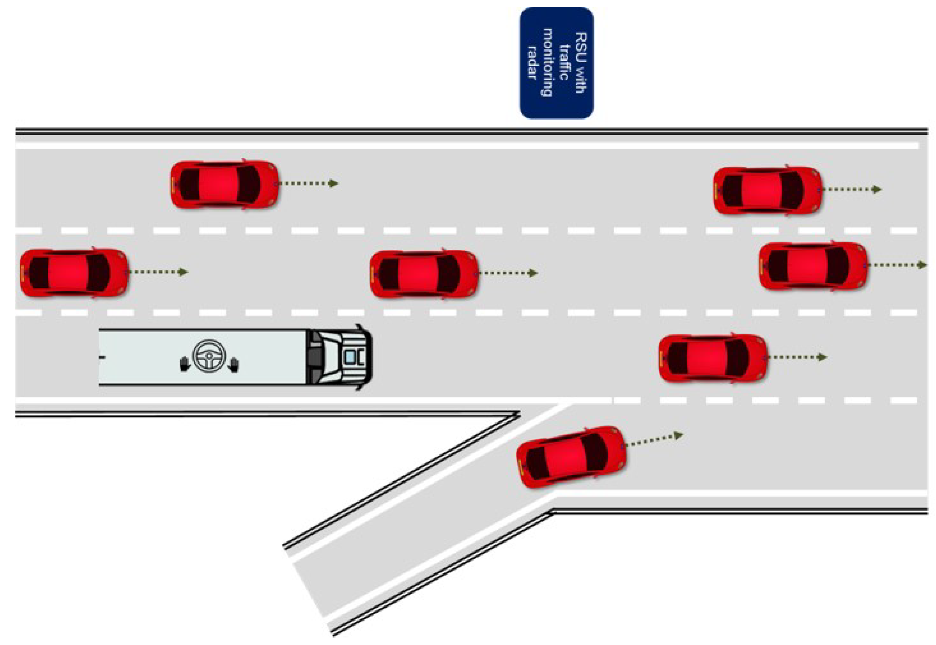
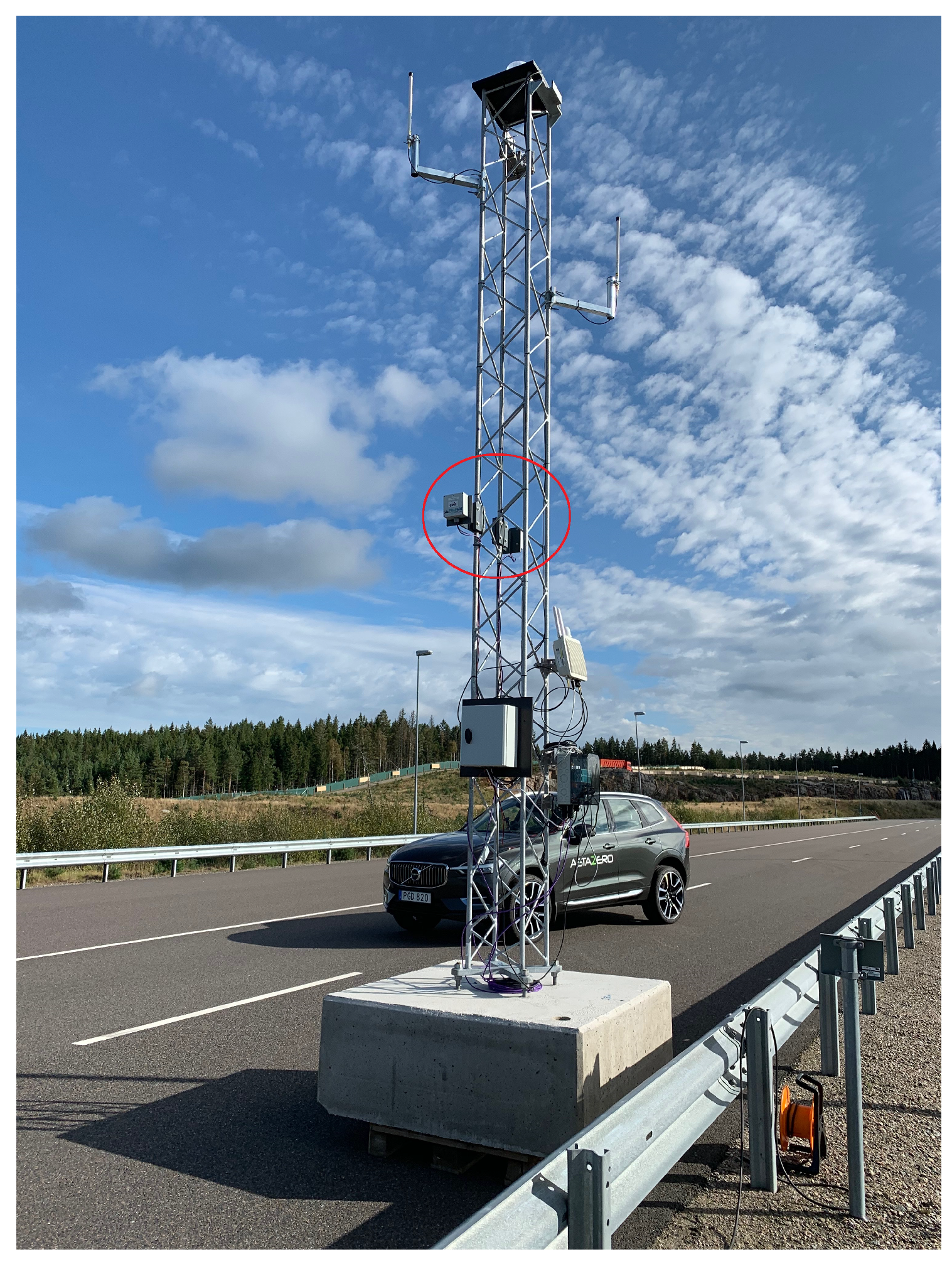
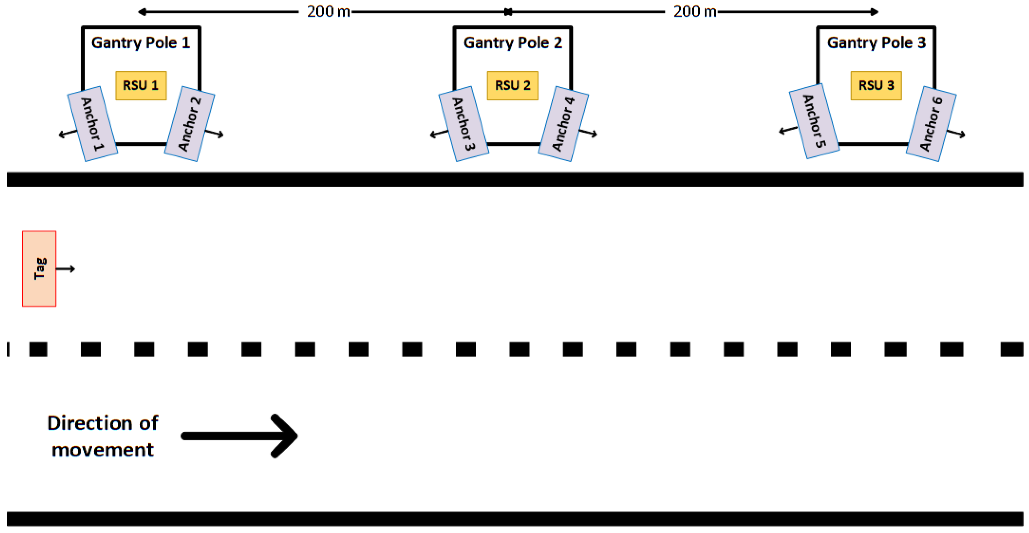
  • Equip the Road Side Units (RSUs) located aside the roads with UWB fixed nodes for redundancy and robustness in areas where the coverage of GNSS is poor. These ranging units will allow the automated vehicle to calculate its distance to known points on the road.
  • Development of an accurate and robust positioning solution based on the data fusion of UWB ranging estimates together with inertial and odometry data. This solution enhances the vehicle’s positioning in those environments where the GNSS signal reception is limited or impossible.
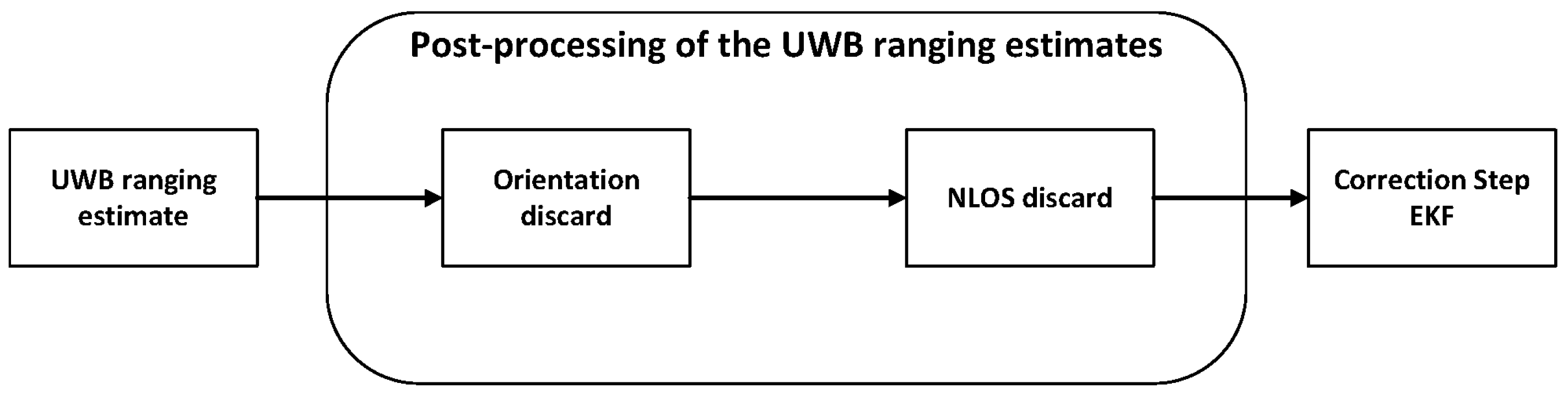
  • An Extended Kalman Filter (EKF) has been built for fusing the UWB ranging estimates with the on-board data of the vehicle. Moreover, an algorithm for post-processing the UWB ranging estimates has also been developed. The combination of both algorithms computes an accurate and reliable position over time, enhancing the individual performance of the different data sources.
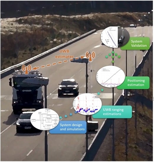
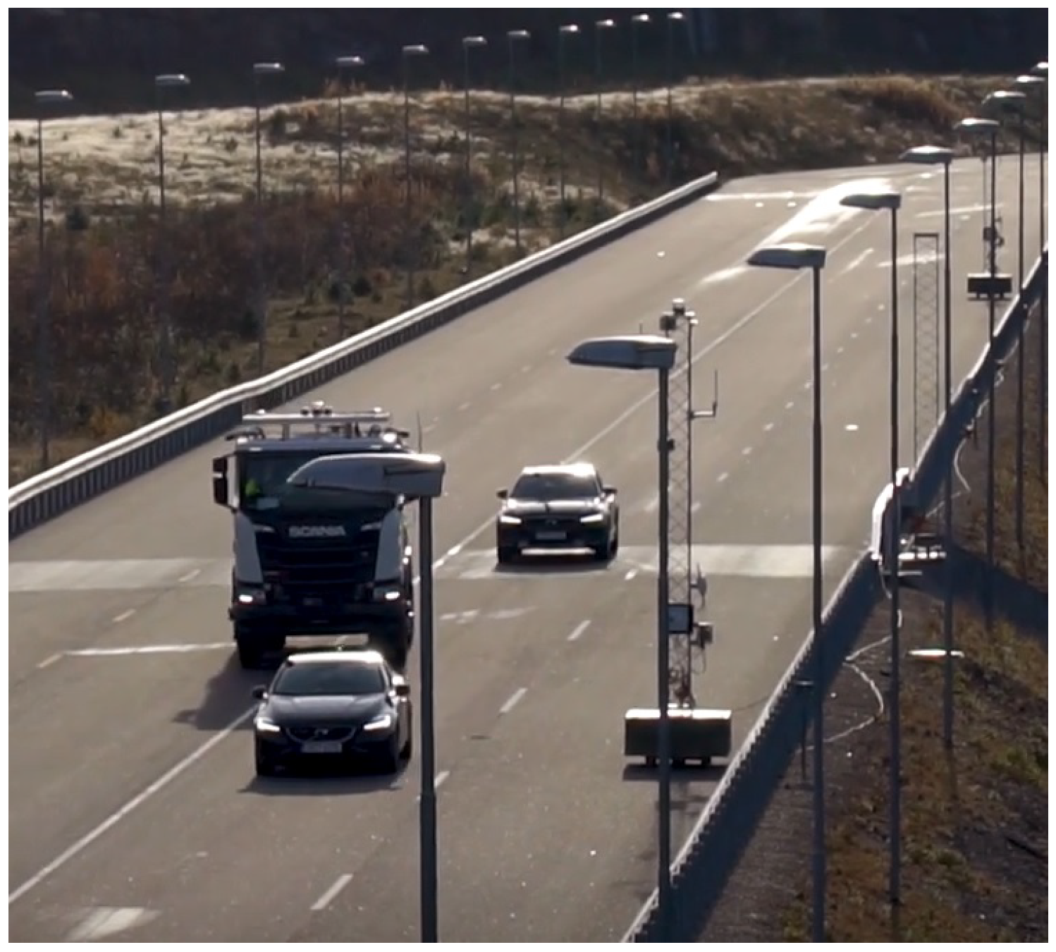
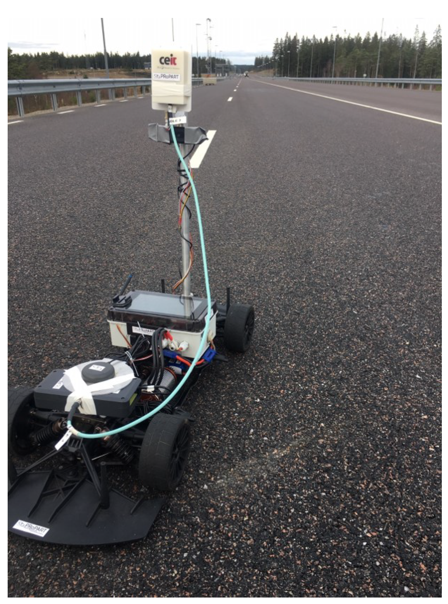
  • Validation of the proposed solution by different tests performed in both a simulated environment and a real environment. On the one hand, the simulations have been carried out for proving the correct operation of the proposed solution in its initial design. On the other hand, the real tests have been carried out on the Astazero proving ground [13] in Sweden, using a relevant setup for the PRoPART use case. For these tests, a Radio Control car (RC car) developed by RISE (Research Institutes of Sweden) has been used as testing platform.
  • Accurate UWB sensor based on an external antenna connected through a cable to achieve a flexible deployment of our solution. To our best of knowledge, none of the research works found in the literature proposes such a flexible solution.
The remainder of this paper is organized as follows. In Section 2, some related work are introduced. In Section 3, the methodology is described. The details of the implementation of our approach are presented in Section 4. Section 5 provides the experimental results and comparison of the accuracy and range of the UWB solution for different trajectories. Finally, the conclusions are summarized in Section 6.

2. Related Work

2.1. Introduction

Over the past two decades there has been an increase in the research and development of autonomous vehicle technologies. An autonomous vehicle is capable of sensing its environment and move with no human input. These vehicles combine a large variety of sensors to perceive their surroundings, such as radars, lidars, ultrasonic sensors, GPS, odometry and Inertial Measurement Unit (IMU). The information provided by these sensors combined with advanced control systems, allow the vehicles to identify appropriate navigation paths, as well as obstacles and relevant signals [1].

2.2. Precise Outdoor Positioning

An outdoor positioning system is a system that identifies and tracks the location of objects or people in real time in an outdoor environment. Traditionally, this global location has been provided by a GNSS system. The GNSS data are usually combined with an Inertial Navigation Solution (INS) in order to monitor at a high rate the exact location of the target. As previously mentioned, fusing data from these sources can provide, under good GNSS conditions (clear view of the sky), a reliable and accurate position.
However, there are certain environments in which the performance of GNSS systems is compromised due to tunnels and obstacles that block the satellite signals. In these environments, the GNSS receiver situated on the target is not able to track a sufficient number of satellites for computing an accurate position. Or in the worst case, the GNSS receiver completely looses the signals from all the satellites. Hence, one of the main challenges of outdoor positioning is to face the possible interferences and signal outages of GNSS systems.
In order to overcome these situations, different positioning technologies have been studied. One of these technologies is UWB which can be used for enhancing the positioning performance and guaranteeing a continuity and availability in the positioning.
In the literature, several examples based on the fusion between UWB sensor-based and INS sensor-based positioning systems can be found. This sensor fusion allows to remove or minimize the limitations of each technology, enhancing the accuracy and reliability of the final positioning solution.
Traditionally, UWB positioning solutions have been used for tracking in indoor environments, since the UWB radio technology is capable of providing accurate positioning information. In [6] the indoor positioning performance of an Ultra-Wideband/Inertial Measurement Unit (UWB/IMU) solution based on an 8-state EKF is proposed and tested in real time. The dynamic test results, carried out in a simulated platform and also in a real indoor environment, show better performance of this fusion than using an stand-alone UWB positioning solution. In [7], a Sage–Husa Fuzzy Adaptive Filter (SHFAF) solution based on INS/UWB positioning is proposed for autonomous indoor mobile robots. Their solution was validated in real time by carrying out dynamic tests in both a simulated environment (using Gazebo simulator) and a real scenario (using a mobile robot). This approach obtained a position estimation error of less than 20 cm in the 88.6% of the measurements. In [8] an UWB/IMU fusion algorithm based on the EKF and Unscented Kalman Filter (UKF) was studied for indoor navigation. The proposed Indoor Positioning System (IPS) was validated in real time in a real environment by carrying out dynamic tests using a three wheeled omnidirectional robot. The obtained results when applying UKF showed a mean positioning distance error of 7 cm and a maximum positioning distance error of 21 cm.
In the last years, the literature has shown some Ultra-Wideband/Inertial Navigation System (UWB/INS) positioning approaches for outdoor applications. In [4], an UWB/IMU integrated navigation solution based on a EKF is presented for outdoor environments where GNSS signal reception is limited or impossible. The proposed solution for navigating and positioning vehicles and people was validated in a real environment by using a real vehicle moving at a speed up to 18 km/h. For characterising the positioning performance of the UWB/IMU approach, a GNSS solution was used as ground truth. The presented results showed a Root Mean Square Error (RMSE) positioning distance error of around 30 cm in the best case scenario. In [5], the performance of a tightly-coupled GPS/UWB/INS cooperative positioning scheme for vehicles based on a Robust Kalman Filter (RKF) supported by Vehicle-to-Everything (V2X) communication is presented. The proposed solution was dynamically tested in a real environment by using two people walking with the equipment. After post-processing the data, a RMSE 3D positioning distance error of around 57 cm in the best case scenario was achieved. The results showed how the performance of the proposed sensor fusion improve the accuracy and availability of the system in denied GPS environments.
Table 1 shows a summary of the related work. Although some UWB approaches have been found for outdoor applications, the literature shows how UWB technology is mainly used for positioning in indoor applications.
Different publications that propose an UWB/INS positioning solution for IPS highlight that the performance of the UWB systems can be really affected by the environment. Depending on the environment different sources of error, such as multipath interferences, can affect the UWB system. Normally, in an indoor application, these kind of errors can be in somehow determined and mitigated beforehand, since the scenario is known and does not change over time. However, there are cases in which the testing scenario is not known and the mentioned errors cannot be determined previously. For overcoming these errors, [7] proposes an adaptive solution for tracking the dynamic changes in the performance of the UWB ranging estimates.
In an outdoor application, it is not possible to characterise the environment, since it undergoes continuous changes. This supposes a great challenge when working with UWB systems, reflecting in a great variation of the uncertainty of the UWB ranging estimates. In the last years, several publications that evaluate the performance of an UWB/INS positioning solution for vehicles in an outdoor environment have reflected this issue. In general, the aim of these publications is to build an UWB/INS positioning solution that enhances the performance of GNSS based positioning systems, especially, in the areas in which GNSS signals are affected.
Despite the fact of being applications based on vehicle’s positioning, only in [4,14] a real vehicle was used for evaluating the performance of the proposed solution. Furthermore, only in [4] an integrated UWB/IMU positioning solution is proposed, as [14] is more focused on integrating GPS/UWB/Bearing for Vehicle-to-Vehicle (V2V) communications. The fact of using a real vehicle or a similar platform that can emulate its behaviour to test the proposed positioning solution provides a better understanding of its performance within a real case scenario.
In conclusion, UWB based positioning systems are widespread in indoor positioning applications. In comparison, little research has been made in terms of outdoor positioning, indicating that more work is needed in order to evaluate their performance in outdoor applications.
Hence, this paper proposes an outdoor positioning system based on a sensor fusion between an UWB based ranging solution and an INS positioning system. This sensor fusion makes use of the UWB ranging estimates to calibrate the position computed from the vehicle’s inertial and odometry data to avoid long term drifts and reduce its uncertainty. Furthermore, the proposed system has been validated in a real outdoor environment emulating a relevant setup for the PRoPART project. On the other hand, our proposal is based on an external antenna connected through a cable to achieve a flexible deployment of our solution. This cable solution does not comprise the accuracy of our system which obtains good results in real tests. To our best of knowledge, none of the research works found in the literature proposes such a flexible solution.

3. Methodology and Experimental Procedure

As mentioned, this paper is focused on the study of a positioning system based on the UWB/IMU/Odometry fusion as a complementary system to those based on GNSS signals. Our approach is based on an UWB system formed by several fixed UWB nodes, called anchors, with a known position and one mobile UWB node, called tag, which is located in the vehicle. This system will compute UWB ranging estimates between the different UWB anchors and the UWB tag in order to correct over time the vehicle’s position computed from its on-board data. To evaluate the performance of this positioning system, it is necessary to select an appropriate measurement procedure as well as a clear statistical analysis of the results.

3.1. Methodology

In a positioning system, its accuracy is studied analysing the distance error, ϵ p , made in the estimation of the position. In this paper, this error is defined as:
ϵ p = ( x x ^ ) 2 + ( y y ^ ) 2 ,
where ( x , y ) are the real Cartesian coordinates of the tag position and ( x ^ , y ^ ) represent the estimated coordinates of the tag position. The figures of merit selected to evaluate the performance of the proposal are the mean distance error, the standard deviation of the distance error (and the variance) and the RMSE explained in detail in [17].

3.2. Experimental Procedure

The experimental procedure followed to perform this work was organised in two steps:
  • Step 1: use of a dynamic platform simulator to design the algorithms for fusing the data coming from UWB sensors, odometry and IMU.
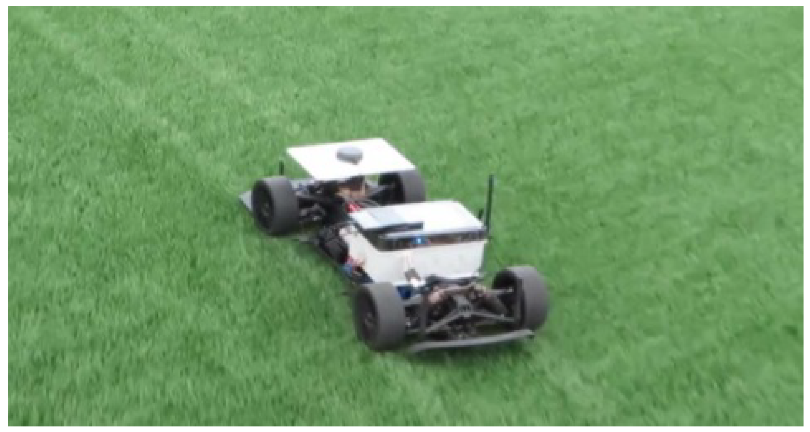
  • Step 2: use a vehicle, an RC-Car, to collect data in a real and representative scenario to validate the proposed positioning system.
These steps are explained in more detail in the following.

3.3. Step 1: Dynamic Platform Simulator

A simulation tool has been used to emulate a real case scenario (similar position and number of anchors, same data rate, etc.). Using a simulator has been very helpful to obtain an initial characterisation of the EKF variables before carrying out the real tests. This simulator has been used to obtain an initial characterisation of the EKF variables before carrying out the real tests.
Basically, the simulation tool permits to emulate the behaviour of a real RC car test platform by simulating its odometry and inertial data [18]. Thus, the user can get information about the orientation, the travelled distance, the real position or the velocity of the simulated vehicle at the desired rate. It should be pointed out that some inertial parameters, as the acceleration, are not provided by the simulator. Apart from simulating the odometry and inertial data, the RC car simulator allows the user to build an UWB ranging system. The user can set different UWB anchors and their positions, as well as the rate in which the ranging estimates will be generated. Once the UWB ranging system has been set, the RC car simulator provides ranging estimates at the configured rate containing the distance between the simulated car and the UWB anchors.

3.4. Step 2: Radio Control Car

The RC car, shown in Figure 1, is a testbed for research and development within the areas of autonomous driving and accurate positioning. This is able to achieve high position accuracy and low latency using low-cost hardware by fusing data from multiple sensors (accelerometer, gyroscope, odometry, and Real-Time Kinematic Satellite Navigation (RTK-SN)) to take advantages of their individual strengths [19]. This testbed is scalable to a wide range of model vehicles. The custom hardware and all involved software are open source for easy development and extension.
The RC car has been the testing platform used for the real tests of the outdoor positioning system proposed in this work. This platform has been extended to embed the HW and SW related to our UWB data fusion solution. Furthermore, the RTK-SN system of this platform has been used as ground truth to compare the accuracy obtained.

4. Design of the Outdoor Positioning System

To obtain an accurate position of the RC car, our proposed positioning system makes use of different data sources: the UWB ranging system, Odometry and IMU. This data fusion makes the positioning more robust. Figure 2 shows the architecture of the developed positioning system.
It is important to point out that this system is a two dimensional model, meaning that it only calculates the x and y position of the RC car. As it can be seen in Figure 2, the developed positioning system is based on an EKF. On the one hand, the prediction step of the EKF is applied each time new data from the RC car sensors are received. On the other hand, each time a new UWB ranging estimate arrives into the system, the correction step of the EKF is applied for correcting the last position of the RC car computed by the prediction step.
To initialise the positioning system it is necessary to know the initial position of the RC car. The accuracy of the initial position is significantly important as it affects the accuracy of the positioning system during the initial steps. In the tests carried out in this work, the initial position of the RC car corresponds with the one provided by its RTK-SN positioning system based on GNSS signals. This RTK positioning system provides a two-dimensional position of the car with an error lower than 5 cm under good conditions for the GNSS signals [19].
The main purpose of the overall solution is to provide a high rate accurate position of a vehicle based on UWB ranging estimates combined with inertial and odometry data from the vehicle sensors. This data combination is done through two different processes:
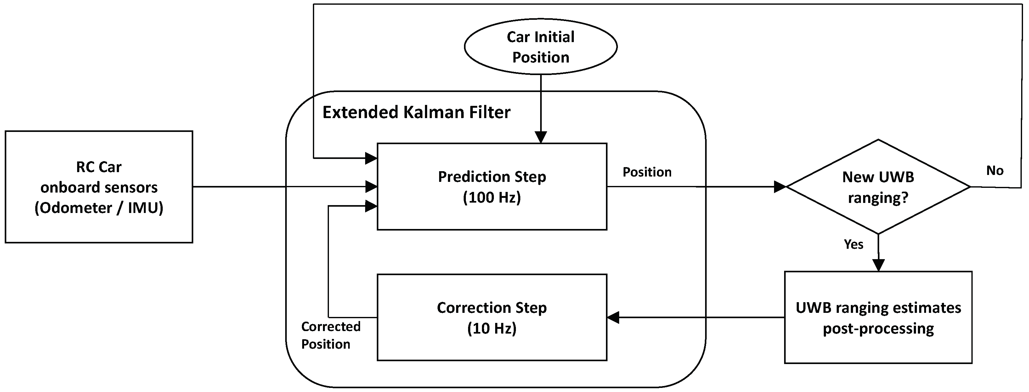
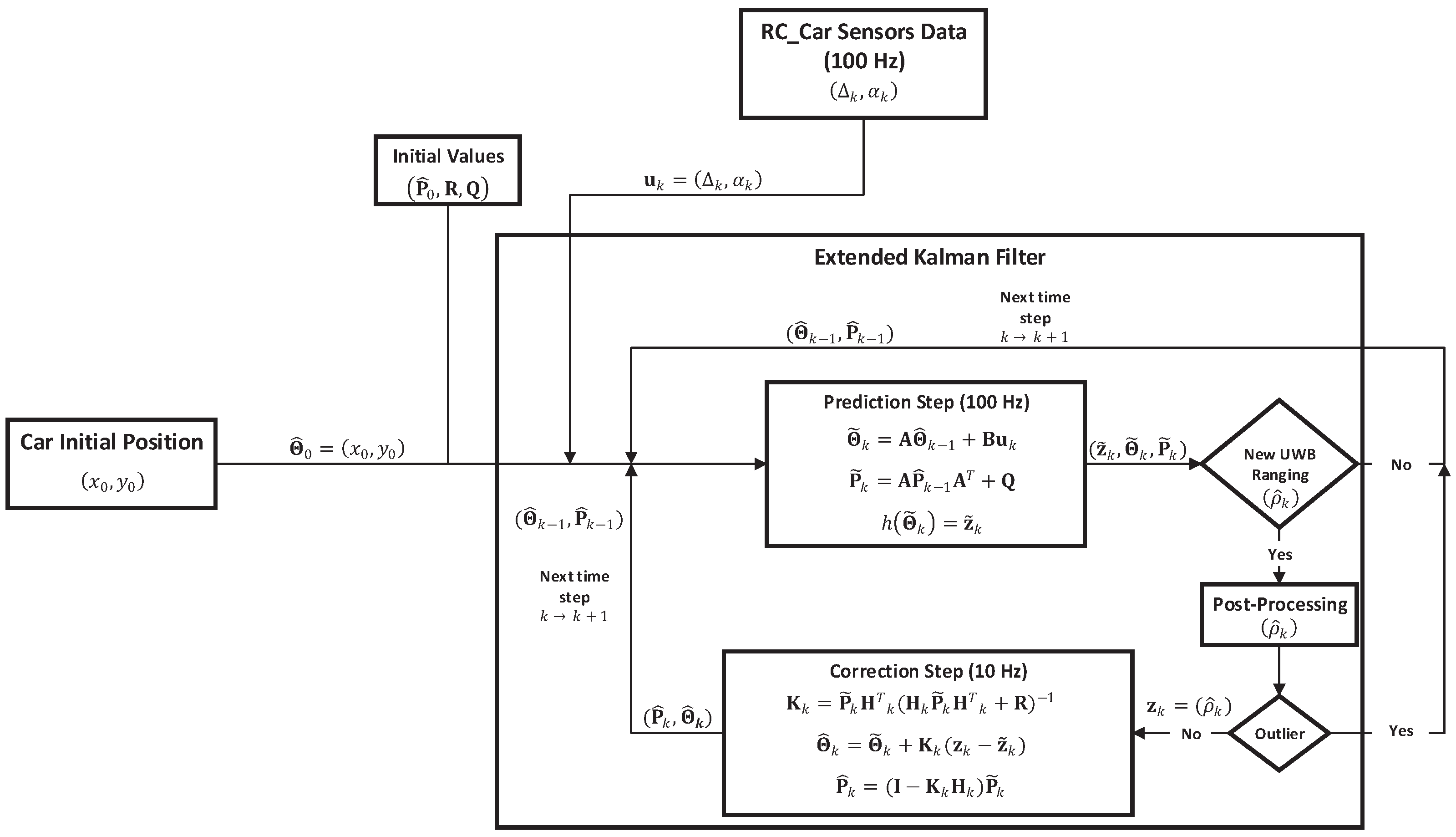
  • Updating the RC car position. This is carried out in the prediction step of the EKF. This step is applied each time new odometry and inertial data of the RC car on-board sensors arrive into the system, resulting in a new position of the RC car. Note that the data of the RC car on-board sensors are generated at a data rate of 100 Hz, indicating that every 10 ms the prediction step of the EKF is applied.
  • Correcting the RC car position. This is accomplished in the correction step of the EKF. This step is applied each time a new UWB ranging estimate arrives into the system, correcting the last position of the RC car computed in the prediction step. The main idea when correcting periodically the position computed by the prediction step is to bound its positioning error over time. Note that the UWB ranging estimates are generated at a data rate of 10 Hz, indicating that every 100 ms the correction step of the EKF is applied.

4.1. Proposed Extended Kalman Filter

The proposed Extended Kalman Filter makes use of the travelled distance and the orientation of the RC car provided by the odometry and IMU, respectively. These data are used to periodically update its position during the prediction phase. This position is corrected over time in the correction phase by using UWB ranging estimates. Therefore, the RC car position is the only navigation state included in the state vector Θ .
Θ k = x k y k .
Each time the algorithm receives new data from the on-board sensors of the RC car, the a priori state vector Θ ˜ is updated by using the following equation:
Θ ˜ k = A Θ ^ k 1 + Bu k .
where Θ ˜ k is the new a priori state at timestamp k, Θ ^ k 1 is the previous a posteriori state at timestamp k-1 and u k is the input vector that includes the travelled distance by the RC car in the x and y directions between timestamps k−1 and k. During the prediction phase of the algorithm, the a priori error covariance matrix P ˜ k is also computed based on the a posteriori error covariance matrix P ^ k 1 and the process noise covariance matrix Q . This matrix includes the noise from both the odometry and IMU data. Note that, if no new UWB ranging estimates are available after the prediction phase, the computed a priori estimate is used as the previous a posteriori estimate ( Θ ^ k 1 , P ^ k 1 ) during the next iteration of the EKF.
The computed a priori estimation is corrected over time in the correction phase by making use of the UWB ranging estimates. This phase is applied each time a new UWB ranging estimate arrives into the system after post-processing it. The main idea behind post-processing the UWB ranging estimates is to discard Non Line-Of-Sight (NLOS) measurements that may compromise the accuracy and robustness of the proposed solution. The developed algorithm for post-processing the UWB ranging estimates is described in depth in Section 4.2.
Therefore, if an UWB ranging estimate is classified as an outlier, it is discarded and the correction phase is not applied. In this situation, the a priori estimate of the EKF is used as the previous a posteriori estimate in the next iteration of the EKF. Otherwise, this measurement is employed for correcting the a priori information. For this, the measurement estimation h ( Θ ˜ k ) has to be computed. This function relates the a priori state Θ ˜ k with the UWB ranging estimate by calculating the euclidean distance between the position of the UWB tag node located in the RC car and one of the anchors that takes place in the UWB ranging estimate. Note that, the position of the anchor is well-known. Hence, the position of the tag by knowing its relative position with regard to the RC car position is computed. Due to the fact that Equation (4) is not linear, an EKF has been considered.
h ( Θ ˜ k ) = ( x t a g k x a n ) 2 + ( y t a g k y a n ) 2 .
Once the function h ( Θ ˜ k ) has been computed, the Jacobian matrix H k can be directly derived as:
H k = δ ( h ( Θ ˜ k ) ) δ Θ k = ( x t a g k x a n ) / h ( y t a g k y a n ) / h .
The matrix H k allows to compare the a priori error covariance matrix P ˜ k with the measurement noise covariance matrix R , which represents the error of the UWB ranging estimates. By making use of these two sources of information the algorithm is able to compute the matrix K k , also known as the Kalman gain. Basically, the matrix K k tries to minimise the a posteriori error covariance P ˜ k by giving more weight in the a posteriori estimate either to the UWB ranging estimate or to the a priori estimate computed from the RC car on-board data. Figure 3 shows a basic architecture of the proposed Extended Kalman Filter.
In this algorithm both the measurement and process noise matrices R and Q have a constant value over the filter iterations. Meaning that, for obtaining an optimal performance of the filter, their value must be correctly tuned depending on the application. An incorrect selection of these matrices can lead to inaccurate positioning results or even to the filter divergence.

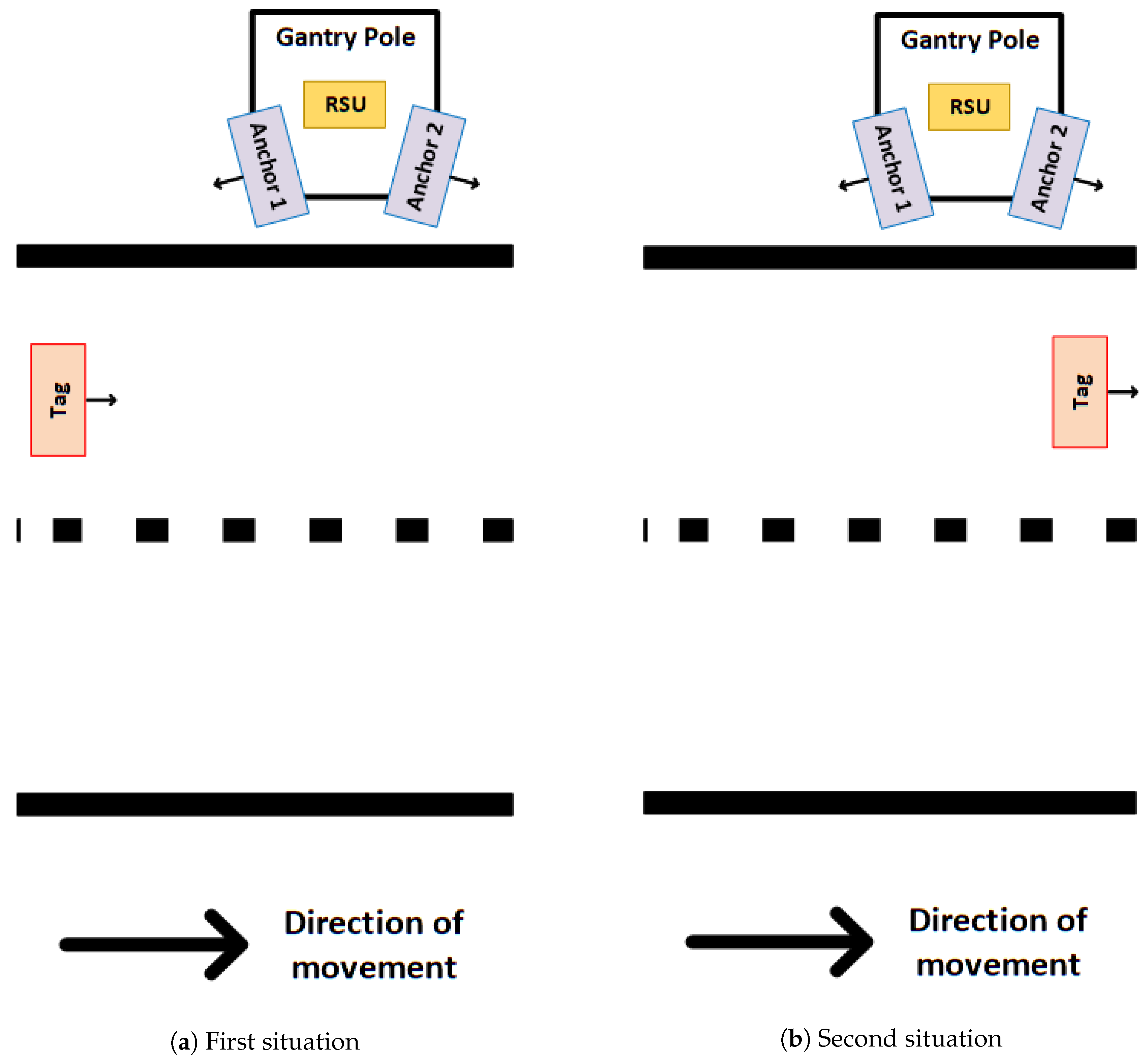
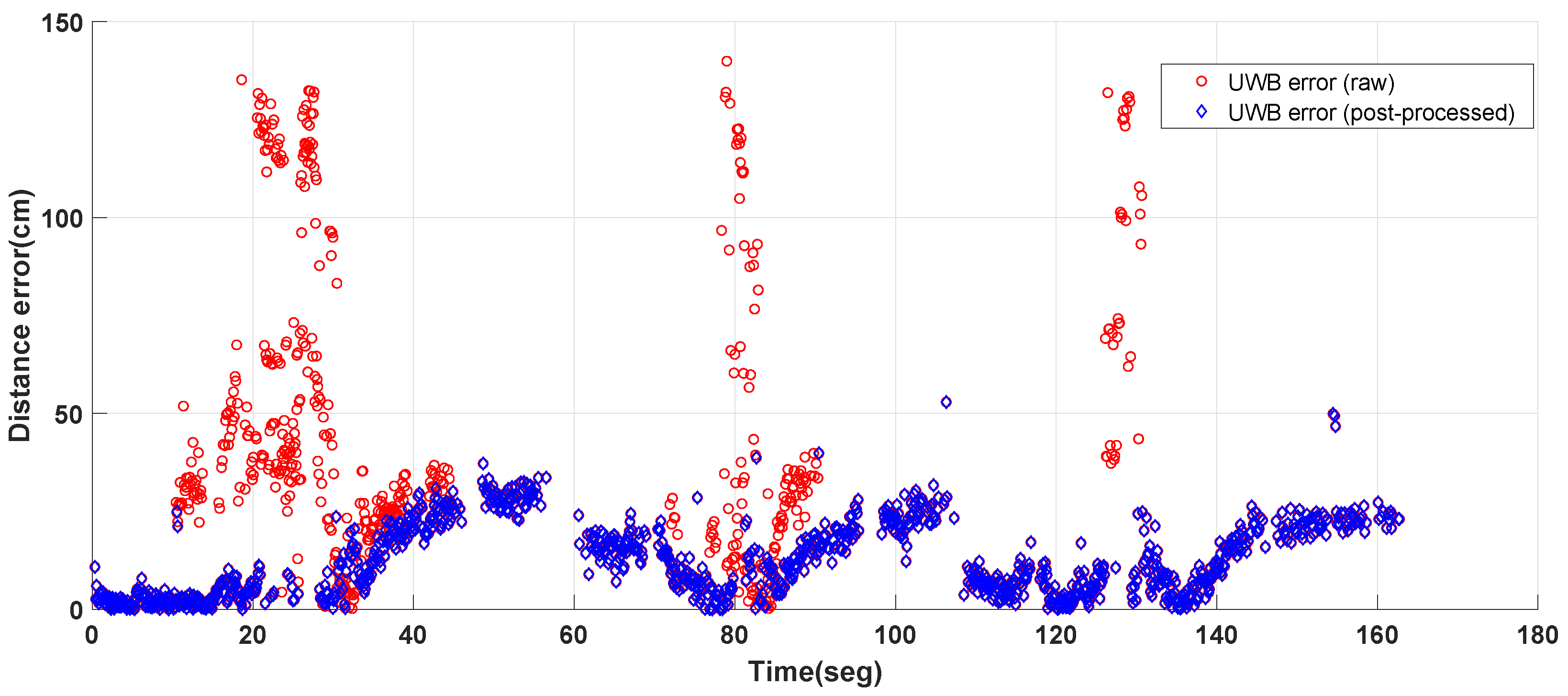
4.2. Proposed Algorithm for Post-Processing the UWB Ranging Estimates

As previously mentioned, post-processing the UWB ranging estimates is necessary to eliminate the Non Line-Of-Sight (NLOS) measurements. The objective is to avoid using high error data in the EKF correction phase that can lead to the filter divergence. Basically, this algorithm is based on two steps, see Figure 4.
The first step consists on an orientation detection depending on the relative orientation between the anchor and tag antennas. Note that, this detection is made by knowing the direction followed by the RC car and the spatial orientation of the UWB nodes located on the RSUs with regard to the UWB tag. By combining these data, it is possible to detect the UWB ranging estimations of those UWB anchors that are facing the UWB tag. In the used setup, see Section 5.2 for further details, two UWB anchor nodes and one Road Side Unit (RSU) were located on a gantry pole. Thus, each gantry pole includes two different UWB anchor nodes with a different position and orientation. Therefore, due to this difference in the position and orientation of the UWB anchor nodes there are two possible situations, see Figure 5. It is important to highlight that the black arrows situated near the UWB nodes represent the direction in which their antennas are pointing. Whereas, the opposite planes to the arrows direction represent the antennas ground planes.
On the one hand, Figure 5a shows the first possible situation regarding the relative orientation between the tag antenna and the anchors ones. In this case, the antenna of Anchor 1 is directly pointing to the tag antenna. Whereas, Anchor 2 antenna is not directly pointing to the tag antenna. In the situation in which the anchor antenna is not pointing to the tag, there is a higher probability of obtaining NLOS UWB ranging measurements. Therefore, the implemented orientation detection algorithm will only take into account the UWB rangings estimates provided by the anchor whose antenna is directly pointing to the UWB tag node, not considering the ones provided by the other anchor. Meaning that, in this situation, only the UWB ranging estimates provided by Anchor 1 will be taken into account.
On the other hand, Figure 5b shows the second possible situation that can occur due to the used setup. In this case, the algorithm for the orientation detecion will only take into account the UWB ranging estimates of Anchor 2 since its antenna is directly pointing to the tag. Thus, the UWB ranging estimates of Anchor 1 will be discarded.
The second step is to detect and discard the NLOS UWB ranging estimates. To do so, the implemented algorithm computes the distance, ρ k n , between the anchor that takes part on the evaluated UWB ranging estimate and the UWB tag at timestamp kn, being n the n-instants that have elapsed since applying the previous correction phase of the EKF. This distance is assumed to be the real distance between both UWB nodes at timestamp kn. This distance is computed by using the tag position at timestamp kn and the anchor position that takes part in the evaluated UWB ranging estimation.
ρ k n = ( x t a g k n x a n ) 2 + ( y t a g k n y a n ) 2 .
Note that, if the elapsed time between k−n and k is larger than a maximum time limit, it is assumed that the tag position at timestamp k−n cannot be used to classify the new UWB ranging estimate. Therefore, this new UWB ranging estimate is assumed as a LOS measure and the correction phase of the EKF is applied. This maximum time limit is highly related with the vehicle’s speed. Meaning that, it will be higher if the vehicle’s speed is lower because the vehicle’s positions at timestamps k−n and k will be closer, and higher otherwise.
Then, the travelled distance, k n k , by the vehicle between k−n and k is calculated from the odometry data. Finally, a maximum and a minimum limit can be obtained in order to classify the UWB ranging estimate.
m a x _ d i s t a n c e k = ρ k n + k n k .
m i n _ d i s t a n c e k = ρ k n k n k
The evaluated UWB ranging estimate should be between both limits. However, knowing that the RC car position has a certain amount of error and that the ranging estimates usually present an uncertainty with regard to the real distance, these limits are increased by a constant value C.
m i n _ d i s t a n c e k + C ρ ^ k m a x _ d i s t a n c e k + C
If the UWB ranging estimate is not situated between these limits, it is classified as an NLOS UWB ranging estimate and discarded, not applying the correction phase of the EKF.

5. Experiments and Results

In GNSS denied areas, the vehicle position is computed directly from its inertial and odometry data. If the elapsed time without having GNSS data is not significantly high, the positioning information will remain accurate enough, as the inertial and odometry data alone can provide accurate positioning estimates over short periods. However, these data have a tendency to increase their error with time without an upper limit. Meaning that, if GNSS signals are not available over long time periods the vehicle position will accumulate a high positioning error. For avoiding this behaviour, as this research work proposes, UWB ranging estimates can be used as a complementary source of information for correcting the computed position over time from the inertial and odometry data of the vehicle.
Unlike inertial and odometry data, the UWB ranging estimates have a bounded error over time, indicating that their error does not increase with time. Therefore, the main goal of the performed tests is to analyse how the accuracy and reliability of the vehicle position is enhanced by including an alternative positioning system based on UWB ranging estimates.
As mentioned in Section 3.3, the simulation platform has been used to characterize the EKF algorithm and test the solution at its initial stage. This platform presents some limitations when trying to replicate a real scenario. By using the simulator, it has not been possible to take into account the fact that the UWB tag has an external antenna physically separated from the module. Furthermore, the different errors that are introduced by the simulator on the positioning data do not correspond with the ones observed in a real case scenario, being these errors a relatively simple approximation of the real ones. Regarding the UWB system, the used simulator does not reflect the distance error highly related to the spatial location of the UWB nodes. Furthermore, this platform is not capable of emulating the reflections that an UWB system may undergo in an outdoor environment. Due to these limitations, the main idea when testing the developed algorithm with the simulation platform has been to prove its correct performance during its initial development phase.
After this initial validation of the solution performance at a simulation level, different real tests have been carried out to validate the final proposed solution in a real scenario. The main idea behind these tests is to verify the positioning accuracy and continuity of the developed UWB solution in a simpler scenario (see Section 5.2) than the one used in the PRoPART use case. The results of these tests are presented in Section 5.3.

5.1. Propart Use Case

The PRoPART use case is to perform an automated lane change to the left on the highway that allows vehicles to enter on the right, as Figure 6 shows. That is why the UWB anchor nodes have been installed on one side of the road close to the RSUs. Each RSU integrates a GNSS base station, a radar and V2X communications device. To complete the system, an UWB tag node is placed on-board the heavy vehicle (a real truck) with the aim of providing a precise positioning when the GNSS signal is lost. Note that, the antenna of the UWB tag node is located outside the heavy vehicle to avoid the interferences generated by the vehicle’s structure. Whereas the electronic is kept within the vehicle. Thus a flexible cable is used to connect both parts.
From this use case, the PRoPART project imposes the following challenges to the UWB measurements: high accuracy in the centimetre level, range of hundreds of meters and vehicle speeds up to 40 km/h. The PRoPART concept is explained in detail in [20].

5.2. Real Tests Setup

The positioning solution presented in Section 4 has been tested in the “Multilane Road” of Astazero proving ground in Sweden. During the different tests, an UWB ranging system formed by 6 UWB anchor nodes and 1 UWB tag node has been used. The location of the UWB anchor nodes is the same as the one used in the final demonstration of the PRoPART project.
On the one hand, two UWB anchor nodes were located in a gantry pole at a height of 4 m every 200 m covering a total path for testing of around 600 m (see Figure 7). In each gantry pole as the one in Figure 8, one UWB anchor node had the antenna oriented looking forward, at the direction of the movement, and the antenna of the other UWB anchor node was oriented at the opposite direction of the movement, see Figure 9. Note that, the position of these nodes was well-known due to the fact that each RSU was equipped with a GNSS module. Furthermore, a 3D scan of each RSU was carried out for computing the real position of the UWB nodes with regard to the position of the GNSS antenna.
On the other hand, an UWB tag node was attached to the RC car presented in Section 3.4. This node has been equipped with an external antenna at 0.7 m of height attached to a plastic structure and oriented looking forward, see Figure 10. The main idea behind using the external antenna is to emulate as far as possible the setup used on the PRoPART UWB solution, see Section 5.1.
It is important to highlight that the location of the UWB anchors have been determined to enhance the visibility and accuracy of the UWB system for the real demonstration of the PRoPART project. As previously mentioned, a real truck was used as vehicle within this project. Meaning that, the UWB tag was located higher than in the case of the RC car. Due to the height difference between the UWB anchors and the UWB tag located on the RC car, the elevation angle between these nodes was higher. This angle increased when the RC car approached the RSUs, as the distance between the UWB tag and UWB anchors was reduced. Moreover, the antennas of the different UWB nodes were not omnidirectional. Meaning that, there was a limitation in terms of the opening angle of the antennas. Due to these two facts, the spatial orientation between the UWB anchors and the UWB tag located in the RC car was not the optimal one for the used setup. However, it was not possible to change this location as the mentioned tests were carried out in parallel with the ones of the PRoPART project. Despite this fact, the obtained results have been accurate enough, as will be discussed in Section 5.3.
The UWB system, which is based on the DW1000 chip of Decawave [21], was configured with the parameters presented in Table 2 as the basic configuration to comply with the PRoPART requirements. Furthermore, the UWB tag node was calibrated to work properly using an external antenna connected through a cable of 91.44 cm (36 ) as can be seen in Figure 10.
The trajectory followed by the RC car during the real test has been a straight line within the testing track. As previously mentioned, the idea behind these tests was to validate the positioning and accuracy continuity of the developed positioning solution within the whole trajectory. During these tests, the speed of the RC car was variable, being its maximum speed 20 km/h. Figure 9 shows a graphic representation of the testing scenario and the direction of movement of the RC car.
In the performed tests, the RTK-SN position of the RC car has been recorded and used as ground truth. Note that, the RTK-SN position of the RC car does not correspond with its real position. Nevertheless, as this RTK-SN position has an error lower than 5 cm under good GNSS condition, it is the best approach to verify the accuracy and robustness of the UWB developed solution.

5.3. Tests Results

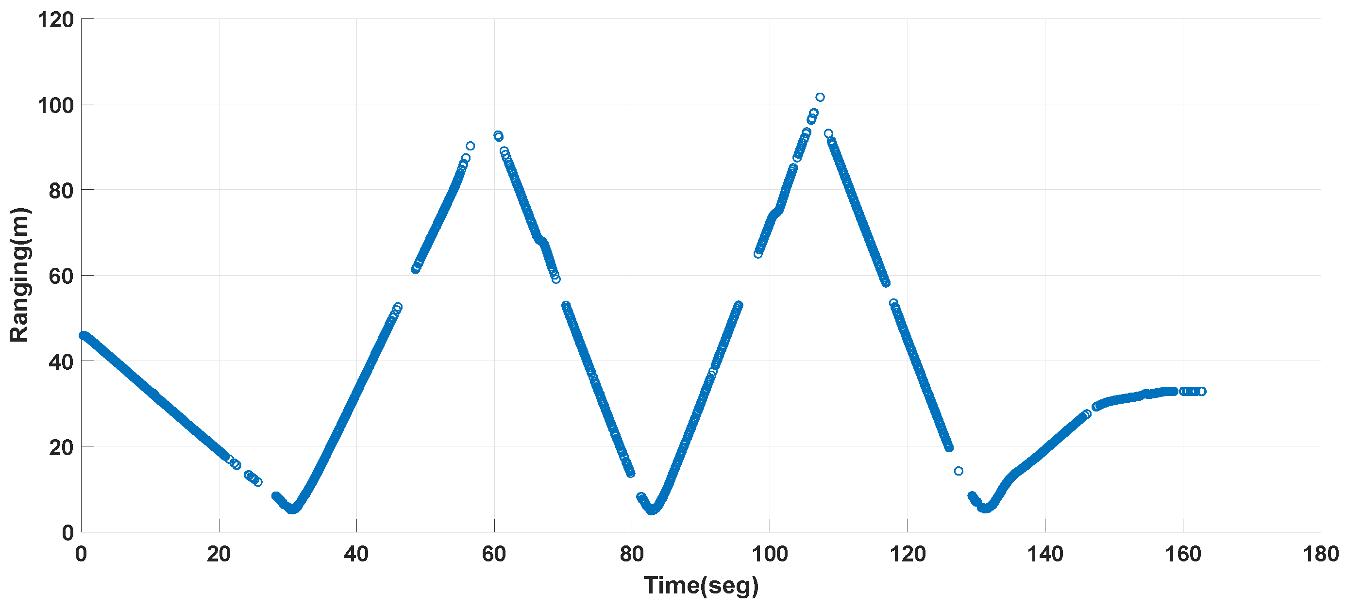
5.3.1. UWB Ranging Estimates
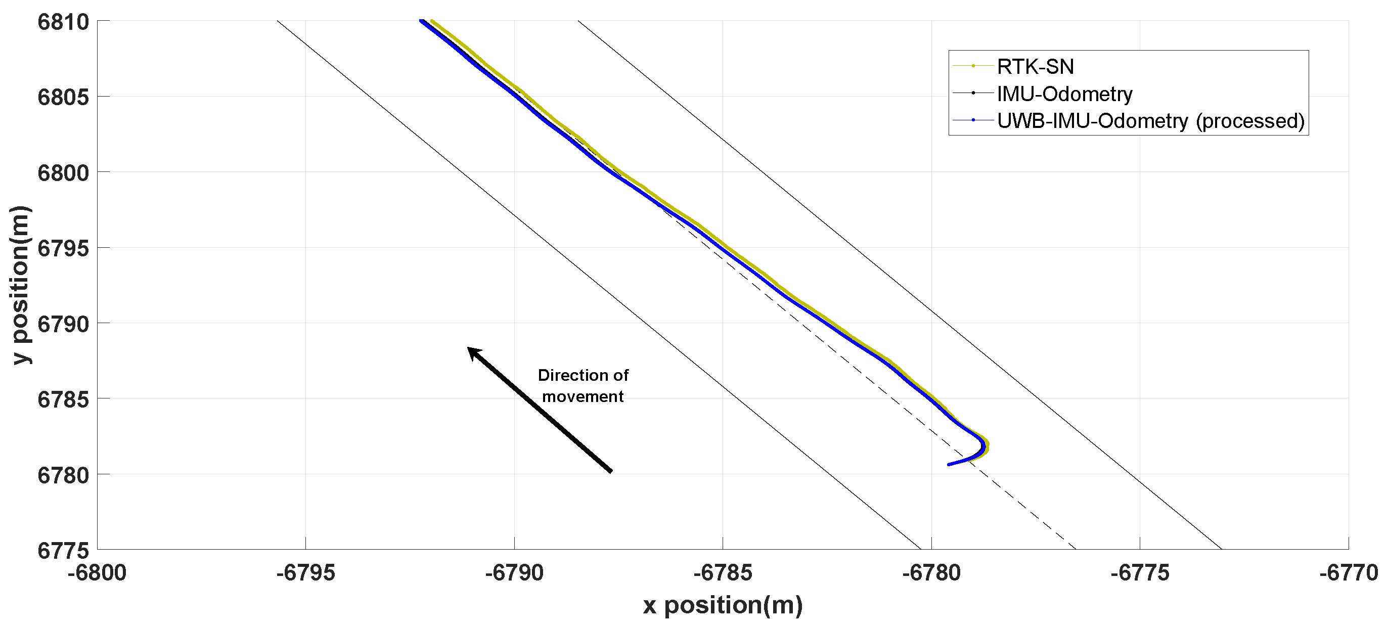
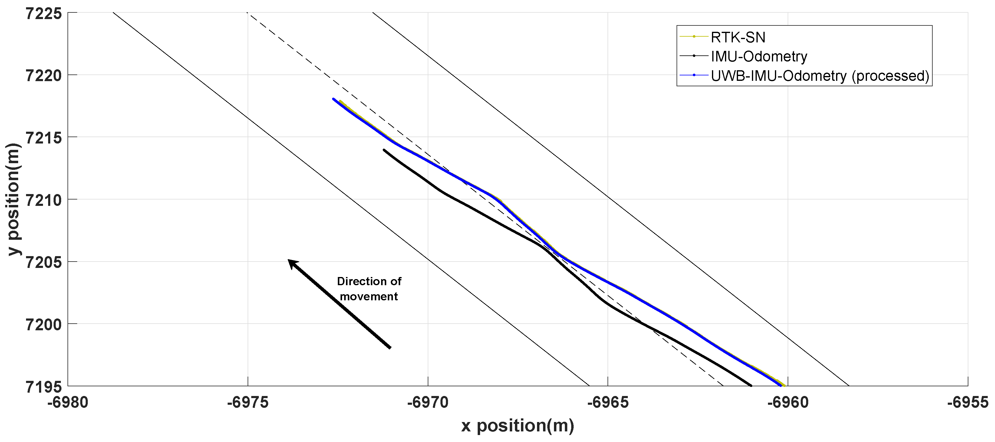
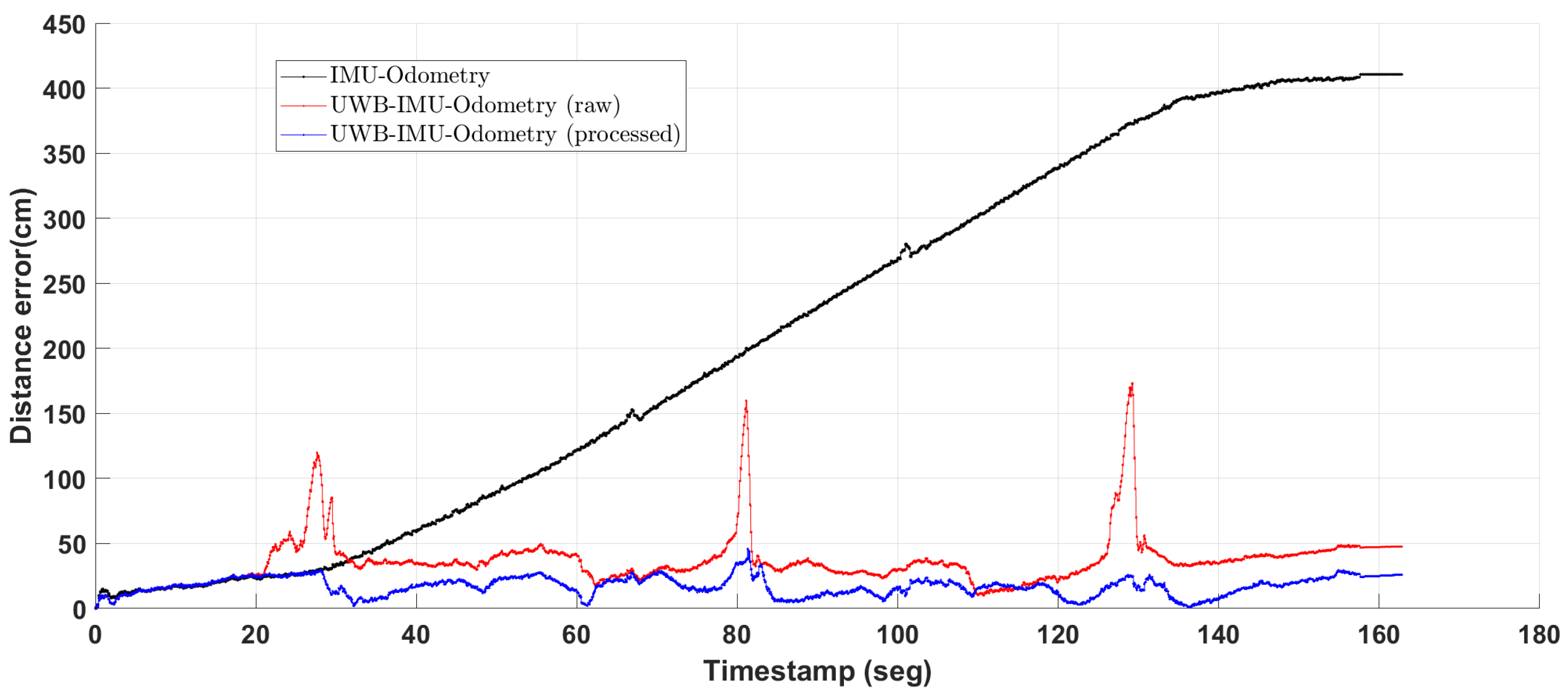
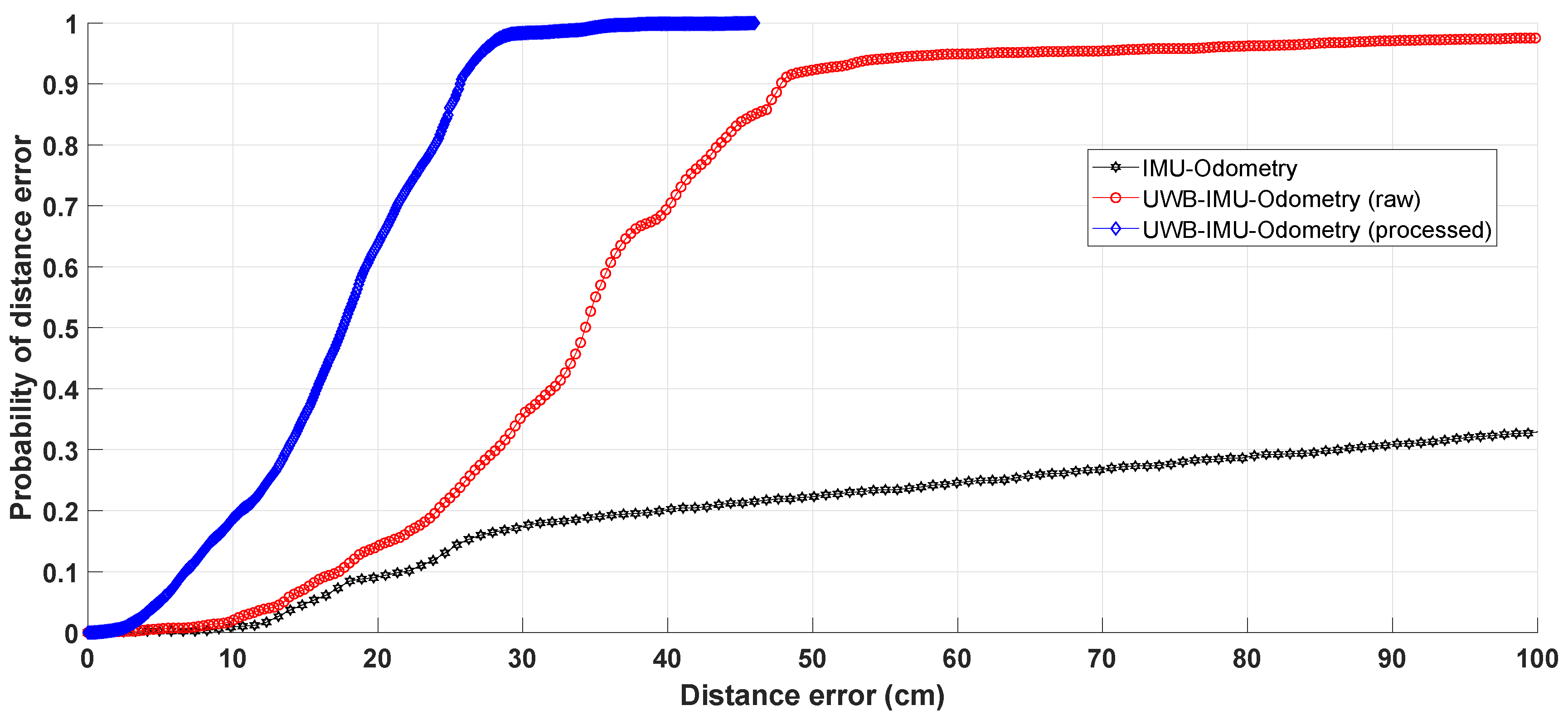
When evaluating the performance of the proposed positioning solution, the first step is to analyse the UWB ranging estimates over the followed trajectory. In order to avoid using NLOS UWB measurements, the UWB ranging estimates are post-processed, as explained in Section 4.2.
Figure 11 shows the distance error of the UWB ranging estimates before (UWB error (raw)) and after (UWB error (post-processed)) being post-processed over the whole trajectory. As can be seen, applying our post-processing approach, the maximum distance error is reduced from 140 cm to 55 cm.
Figure 12 shows the value of the post-processed UWB ranging estimates over the whole trajectory. There are some specific areas of the trajectory where we have NLOS measurements as in the areas near the RSUs or some UWB signal loss due to the spatial orientation explained in Section 5.2. Nevertheless, the areas without UWB information do not affect the final results since our approach relies on the data fusion of different technologies as it will be shown in Section 5.3.2. Furthermore, it can be said that the post-processed UWB ranging estimates cover almost the whole trajectory with high accuracy and allow us to achieve a good final solution in terms of reliability and availability.

5.3.2. Positioning

The proposed positioning approach is based on using a complementary system based on UWB to correct the long term drifts of the IMU-Odometry solution. Meaning that, the UWB complementary system is required to achieve an accurate solution to position the vehicle during more than 30 s.
Figure 13 and Figure 14 show a graphical comparison between the RTK-SN trajectory (green line) used as ground truth, the IMU-Odometry trajectory (black line) and the UWB-IMU-Odometry (processed) trajectory (blue line). As stated before, Figure 13 reflects how both the IMU-Odometry and the UWB-IMU-Odometry (processed) trajectories are able to track the RTK-SN trajectory with a similar positioning performance during the initial steps. However, Figure 14 shows that the positioning performance of both trajectories is significantly different at the end of the trajectory. Hence, the UWB-IMU-Odometry (processed) trajectory continues tracking the RTK-SN trajectory in an accurate way while the RC car on-board data trajectory does not track the ground truth. It can be seen how the final point of the IMU-Odometry trajectory is situated far behind the final one of the other two trajectories. This is due to the fact that the IMU and Odometry data have a tendency to drift with time, increasing their error. In consequence, as time passes, the position computed from these data has a higher uncertainty and it is not able to track the real trajectory followed by the vehicle.
Next, we will compare the positioning distance error of the three solutions: only using the RC car on-board data (IMU-Odometry), by merging these data with UWB ranging estimates, both with (UWB-IMU-Odometry (processed)) and without (UWB-IMU-Odometry (raw)) post-processing.
Figure 15 shows the positioning distance error, ϵ p , of the three solutions throughout the trajectory. The obtained results show that the position computed by only taking into account the RC car on-board data (IMU-Odometry) remains accurate enough when the elapsed time is lower than 30 s. However, as can be seen, the positioning distance error is higher than 4 m at the end of the trajectory.
Figure 15 shows how by using an UWB system the positioning performance is significantly enhanced. Combining raw UWB ranging estimates together with the vehicle’s on-board data (UWB-IMU-Odometry (raw)) has a major impact on the positioning performance. As a result of this combination, the positioning distance error is bounded over time and the maximum positioning distance error is reduced up to approximately 175 cm. On the other hand, these data also show that the positioning performance is degraded in the areas close to the RSUs (see Figure 12) with a positioning distance error much higher than in the rest of the trajectory. However, using the post-processing UWB ranging estimates (UWB-IMU-Odometry (processed)) instead of the the raw data, reduces significantly the positioning distance error in those areas. Meaning that, the discard of the NLOS UWB ranging estimates allows to bound the positioning distance error throughout the whole trajectory. Thus, the UWB-IMU-Odometry (processed) solution is able to track in an accurate way the RC car RTK-SN position with its maximum positioning distance error lower than 46 cm over the whole trajectory.
Table 3 shows the statistical data of the positioning distance error, ϵ p , of the evaluated positioning solutions. When only the IMU-Odometry data are used, the RMSE of the positioning distance error is 249.8 cm. Moreover, the 95% of the computed positions have a positioning distance error of 407.3 cm or less. When using raw UWB ranging estimates for correcting the vehicle’s position, the RMSE of the positioning distance error is reduced to 41.4 cm. In this case, the 95% of the computed positions have a positioning distance error of 61.4 cm or less. Finally, the results improve considerably when post-processing is applied. These results show a RMSE of the positioning distance error of 18.6 cm. Furthermore, the 95% of the computed positions have a positioning distance error of 27.1 cm or less.
Figure 16 shows the cumulative distribution function (CDF) of the RC car positioning distance error when computing its position from its on-board data alone and when combining these data with UWB ranging estimates, both with and without post-processing. For the first solution (IMU-Odometry), only 20% of the computed positions have a positioning distance error up to 40 cm. However, these positions are the ones corresponding with the initial phase of the trajectory when the sensors have not accumulated a big error. This is reflected in the fact that the 50% and 99.9% of the computed positions have a positioning distance error up to 200 cm and 410 cm respectively. For the second case (UWB-IMU-Odometry (raw)), the 20% of the computed positions have a positioning distance error up to 24.2 cm, improving considerably the results of the first solution. Furthermore, the 50% and 99.9% of the computed positions present a positioning distance error up to 34.3 cm and 169.6 cm respectively. For the third solution (UWB-IMU-Odometry (processed)), the 20% of the computed positions have a positioning distance error up to 10.6 cm. Additionally, the 50% and 99.9% of the computed positions have a positioning distance error up to 17.6 cm and 44.1 cm respectively, reinforcing again that this last approach achieves the best results in comparison with the previous solutions.

6. Conclusions

Today’s society is undergoing continuous technological changes that seek to improve the actual quality of life and work. As a result of these changes, the vehicle manufacturers and governments are putting a lot of effort in the development of autonomous vehicles to increase road safety and vehicle’s efficiency. For having an optimal performance, an autonomous vehicle needs to have, among other things, a continuous knowledge of its exact location on the road. As it has been recalled, this issue has been traditionally covered by GNSS signals in combination with on-board data of the vehicle. This data fusion provides an accurate, high rate and reliable position of the vehicle under good GNSS conditions, in other words, when the vehicle’s GNSS receiver can track at least four GNSS satellites.
However, this is not always possible, as there are certain environments in where GNSS signal reception is limited or impossible due to numerous obstacles that block the signals. In these areas, the vehicle’s position is computed directly from its on-board data. The problem of these data when used alone is that they have a tendency to drift with time leading to an inaccurate and unreliable position. Therefore, if the GNSS signal reception is affected over long periods, the position provided by this data fusion will be extremely inaccurate, making necessary the use of an alternative positioning system. One of the technologies which can be postulated as a candidate in those areas with no GNSS coverage is the UWB technology. In the last years, much effort has been devoted to study the potential of this technology, specially, in indoor applications.
In our research we intended to evaluate a less-studied aspect of this technology, the use of UWB ranging estimates to track the vehicle’s position in an outdoor environment. The main idea of this work has been to build an accurate and reliable positioning solution based on the combination of UWB ranging estimates together with inertial and odometry data of the vehicle. This study has been characterised inside the scope of the PRoPART project and has made use of a customised UWB ranging system and a RC car as testing vehicle. Meaning that, the used setup has been determined for validating the UWB ranging system in terms of accuracy, coverage and continuity in the PRoPART solution. In addition, our proposal includes an UWB tag in which the antenna is physically separated from the UWB module by making use of an external antenna connected through a cable. This innovative proposal allows to have a flexible solution which can be adapted accordingly to the application without compromising the accuracy.
The proposed positioning solution based on a EKF has been tested by carrying out simulations and real tests. On the one hand, the simulations have allowed us to better understand the performance of the positioning algorithm. On the other hand, the real tests carried out in AstaZero proving ground have proved the enhancement of the RC car positioning when using UWB measurements for correcting the position computed from the RC car on-board data. The obtained results show a RMSE of the positioning distance error over the whole trajectory of 18.56 cm, being the maximum positioning distance error of 46 cm. These results are more accurate and reliable compared to [4], where a RMSE 2D positioning distance error of around 30 cm was obtained in the best case scenario, and [5], where a RMSE 3D positioning distance error of 57 cm was achieved in the best case scenario. However, it should be pointed out that the used setup and the testing application are different than the ones of those publications. Meaning that, for having a fair comparison and, in consequence, extracting more conclusion about the different results the same setup and testing application should be used. Moreover, it can be said that these results overcome in a significant way the ones obtained directly from the RC car on-board data in which the maximum positioning distance error is higher than 4 m. It should be pointed out that, for enhancing the positioning performance, it is really important to avoid using inaccurate UWB ranging estimates in the correction phase of the EKF. In this work, post-processing of these data has been necessary for eliminating the NLOS UWB ranging estimates. By post-processing these data, the RMSE of the positioning distance error was reduced in almost 23 cm and the maximum positioning distance error in 127 cm. Therefore, it can be concluded that using UWB ranging estimates in those areas with no GNSS coverage enables to bound the positioning distance error of the position computed from the RC car on-board data. The use of UWB ranging estimates for computing the vehicle’s position leads to a continuity in an accurate and reliable positioning over time.
To summarise, we have shown the potentials of the UWB technology for enhancing the actual positioning technologies within the vehicle industry. The use of this technology in particular environments, such as tunnels or urban canyons, can overcome the limits that GNSS based positioning technologies are facing. The combination of the actual positioning technology together with UWB ranging estimates can be crucial for guaranteeing continuity in a precise positioning over time in the upcoming era of autonomous vehicles.

Author Contributions

Conceptualization, A.C. and L.Z.-C.; Formal analysis, A.C. and L.Z.-C.; Funding acquisition, A.C.; Investigation, A.C., L.Z.-C., J.S.M. and B.J.S.; Methodology, L.Z.-C.; Project administration, A.C.; Software, L.Z.-C., J.S.M. and B.J.S.; Supervision, A.C. and L.Z.-C.; Validation, J.S.M. and B.J.S.; Writing—original draft, J.S.M. and A.C.; Writing—review & editing, A.C., L.Z.-C., B.J.S. and J.S.M. All authors have read and agreed to the published version of the manuscript.

Funding

This research was funded by the European GNSS Agency under the PRoPART project, H2020 EU project, grant number 776307.

Acknowledgments

This work has been possible thanks to the cooperation between CEIT and RISE, PRoPART partner and coordinator respectively. In particular, the authors would like to thank Benjamin Vedder for his support.

Conflicts of Interest

The authors declare no conflict of interest.

Abbreviations

The following abbreviations are used in this manuscript:
AKFAdaptive Kalman Filter
CDFCumulative Distribution Function
EKFExtended Kalman Filter
FcCentral Frequency
GNSSGlobal Navigation Satellite System
GPSGlobal Positioning System
IMUInertial Measurement Unit
INSInertial Navigation System
IPSIndoor Positioning System
KFKalman Filter
LOSLine-of-Sight
NLOSNon Line-of-Sight
PAKFPredictive Adaptive Kalman Filter
PDRPedestrian Dead Reckoning
PRFPulse Repetition Frequency
RC carRadio Control car
RISEResearch Institutes of Sweden
RKFRobust Kalman Filter
RTKReal Time Kinematic
RMSERoot Mean Square Error
RSURoad Side Unit
RTK-SNReal-Time Kinematic Satellite Navigation
SHFAFSage-Husa fuzzy adaptive filter
UKFUnscented Kalman Filter
UWBUltra-Wideband
V2VVehicle-to-Vehicle
V2XVehicle-to-Everything

References

  1. Bimbraw, K. Autonomous cars: Past, present and future a review of the developments in the last century, the present scenario and the expected future of autonomous vehicle technology. In Proceedings of the 12th International Conference on Informatics in Control, Automation and Robotics (ICINCO), Colmar, Alsace, France, 21–23 July 2015. [Google Scholar]
  2. De Miguel, G.; Goya, J.; Fernández, N.; Arrizabalaga, S.; Mendizabal, J.; Adin, I. Map-Aided Software Enhancement for Autonomous GNSS Complementary Positioning System for Railway. IEEE Trans. Veh. Technol. 2019, 64, 11611–11620. [Google Scholar] [CrossRef]
  3. Federal Communications Commission of the United States. Revision of Part 15 of the Commission’s Rules Regarding Ultrawideband Transmission Systems; First Report (Order 02-48, ET Docket FCC 02-8); U.S. Federal Communications Commission: Washington, DC, USA, 2002; pp. 98–153.
  4. Dierenbach, K.; Ostrowski, S.; Jozkow, G.; Toth, C.K.; Grejner-Brzezinska, D.A.; Koppanyi, Z. UWB for Navigation in GNSS Compromised Environments. In Proceedings of the 28th International Technical Meeting of the Satellite Division of The Institute of Navigation (ION GNSS+ 2015), Tampa, FL, USA, 14–18 September 2015. [Google Scholar]
  5. Wang, J.; Gao, Y.; Li, Z.; Meng, X.; Hancock, C.M. A Tightly-Coupled GPS/INS/UWB Cooperative Positioning Sensors System Supported by V2I Communication. Sensors 2016, 19, 944. [Google Scholar] [CrossRef] [PubMed]
  6. Yao, L.; Wu, Y.W.A.; Yao, L.; Liao, Z.Z. An Integrated IMU and UWB sensor Based Indoor Positioning System. In Proceedings of the International Conference on Indoor Positioning and Indoor Navigation (IPIN), Sapporo, Japan, 18–21 September 2017. [Google Scholar]
  7. Liu, J.; Pu, J.; Sun, L.; He, Z. An Approach to Robust INS/UWB Integrated Positioning for Autonomous Indoor Mobile Robots. Sensors 2019, 19, 950. [Google Scholar] [CrossRef] [PubMed] [Green Version]
  8. Guosheng, W.; Shuqi, Q.; Qiang, L.; Heng, W.; Huican, L.; Bing, L. UWB and IMU System Fusion for Indoor Navigation. In Proceedings of the 37th Chinese Control Conference, Wuhan, China, 25–27 July 2018. [Google Scholar]
  9. Fan, Q.; Jia, J.; Pan, P.; Zhang, H.; Sun, Y. An improved INS/PDR/UWB integrated positioning method for indoor foot-mounted pedestrians. Sens. Rev. 2019, 39, 318–331. [Google Scholar] [CrossRef]
  10. Shunkai, S.; Hu, J.; Li, J.; Liu, R.; Shu, M.; Yang, Y. An INS-UWB based collision avoidance system for AGVs. Algorithms 2019, 12, 40–51. [Google Scholar]
  11. Xu, Y.; Shen, T.; Chen, X.Y.; Bu, L.L.; Feng, N. Predictive Adaptive Kalman Filter and Its Application to INS/UWB-integrated Human Localization with Missing UWB-based Measurements. Int. J. Autom. Comput. 2018, 16, 604–613. [Google Scholar] [CrossRef]
  12. Benini, A.; Mancini, A.; Longhi, S. An IMU/UWB/vision-based extended kalman filter for mini-UAV localization in indoor environment using 802.15.4a wireless sensor network. J. Intell. Robot. Syst. Theory Appl. 2018, 70, 461–476. [Google Scholar] [CrossRef]
  13. AstaZero AB—Testing Active Safety. Available online: https://www.astazero.com/ (accessed on 15 March 2020).
  14. Petovello, M.G.; O’Keefe, K.; Chan, B.; Spiller, B.S.; Pedrosa, C.; Xie, P.; Basnayake, C. Demonstration of inter-vehicle UWB ranging to augment DGPS for improved relative positioning. J. Glob. Position. Syst. 2012, 11, 11–21. [Google Scholar] [CrossRef]
  15. Tanigawa, M.; Hol, J.D.; Dijkstra, F.; Luinge, H.; Slycke, P. Augmentation of low-cost GPS/MEMS INS with UWB positioning system for seamless outdoor/indoor positioning. In Proceedings of the 21st International Technical Meeting of the Satellite Division of the Institute of Navigation (ION GNSS 2008), Savannah, GA, USA, 16–19 September 2008. [Google Scholar]
  16. DChiu, S.; MacGougan, G.; O’Keefe, K. Multiple UWB Range Assisted GPS RTK in Hostile Environments. In Proceedings of the 21st International Technical Meeting of the Satellite Division of The Institute of Navigation (ION GNSS 2008), Savannah, GA, USA, 16–19 September 2008. [Google Scholar]
  17. Cadenas, L.Z. Radiofrequency-Based Indoor Location Systems for Ambient Assisted Living Applications. Ph.D. Thesis, University of Navarra, Pamplona, Spain, 2014. [Google Scholar]
  18. Vedde, B.; Svensson, J.; Vinter, J.; Magnus, J. Automated Testing of Ultrawideband Positioning for Autonomous Driving. J. Robot. 2020, 2020, 9345360. [Google Scholar]
  19. Vedder, B.; Vinter, J.; Jonsson, M. A Low-Cost Model Vehicle Testbed with Accurate Positioning for Autonomous Driving. J. Robot. 2018, 2018, 4907536. [Google Scholar] [CrossRef]
  20. Nord, S.; Dietmayer, K.; Tidd, J.; Cortés, A.; Zamora, L.; Varadi, A. PRoPART—Precise and Robust Positioning for Automated Road Transports. In Proceedings of the 25th KA and Broadband Communications Conference, Sorrento, Italy, 30 September–2 October 2019. [Google Scholar]
  21. DW1000 Radio IC. Available online: https://www.decawave.com/product/dw1000-radio-ic/ (accessed on 15 March 2020).
Figure 1. RC car as testbed.
Electronics 09 01238 g001
Figure 2. Architecture of the positioning system developed.
Electronics 09 01238 g002
Figure 3. Representation of the proposed Extended Kalman Filter.
Electronics 09 01238 g003
Figure 4. Architecture of the post-processing algorithm of the UWB ranging estimates.
Electronics 09 01238 g004
Figure 5. Possible situations regarding the relative orientation of the UWB anchors and tag antennas.
Electronics 09 01238 g005
Figure 6. PRoPART use case.
Electronics 09 01238 g006
Figure 7. PRoPART scenario.
Electronics 09 01238 g007
Figure 8. A couple of UWB anchor nodes installed at one gantry pole in the Astazero proving ground.
Electronics 09 01238 g008
Figure 9. Representation of the testing scenario.
Electronics 09 01238 g009
Figure 10. UWB mobile node attached to the RC car.
Electronics 09 01238 g010
Figure 11. Distance error of the UWB ranging estimates.
Electronics 09 01238 g011
Figure 12. UWB ranging estimates after post-processing.
Electronics 09 01238 g012
Figure 13. Comparison of the different trajectories at the beginning of the experiment.
Electronics 09 01238 g013
Figure 14. Comparison of the different trajectories at the end of the experiment.
Electronics 09 01238 g014
Figure 15. Comparison of the positioning distance error, ϵ p , of the different positioning systems.
Electronics 09 01238 g015
Figure 16. Accumulative distribution function of the UWB and the odometry and IMU positioning error.
Electronics 09 01238 g016
Table 1. Summary of the main features of the related work that propose an UWB/INS positioning solution.
ArticleOutdoor
App.
Motion
App.
Sensor
Fusion
Fusion
Alg.
ValidationReal Time
Pos.
[6]NoYesUWB/
IMU
8 state-EKFReal/
Simulations
Yes
[7]NoYesUWB/
INS
SHFAFReal/
Simulations
Yes
[8]NoYesUWB/
IMU
EKF/UKFRealYes
[4]YesYesUWB/
IMU
EKFRealYes
[5]YesYesGPS/UWB/
IMU
RKFRealNo
[9]NoYesINS/PDR/
UWB
AKFRealYes
[10]NoYesINS/
UWB
EKFRealYes
[11]NoYesINS/
UWB
PAKFReal/
Simulations
Yes
[12]NoYesINS/Vision/
UWB
EKFSimulationsYes
[14]YesYesGPS/UWB/
Bearing (V2V)
EKFRealYes
[15]Indoor/OutdoorYesGPS/INS/
UWB
KFRealYes
[16]YesYesGPS/
UWB
KFRealYes
Table 2. UWB system configuration.
ChannelFcBandwidthPreamblePreamblePRFDataMax Mean
LengthCode RateSpectral Density
56489.6 MHz500 MHz128 symbols316 MHz6.8 Mbps−41.3 dBm/MHz
Table 3. Statistical analysis of the positioning distance error ϵ p .
Pos.System μ ^ ϵ p σ ^ ϵ p RMSE ^ ϵ p ϵ p
( P = 95 % )
Max ( ϵ p )
IMU-Odometry205 cm142.8 cm249.8 cm407.3 cm410.6 cm
UWB-IMU-Odometry (raw)36.1 cm20.2 cm41.4 cm61.4 cm173.4 cm
UWB-IMU-Odometry (processed)17.2 cm7.1 cm18.6 cm27.1 cm46 cm

