Abstract
Software-defined networking (SDN) is a new networking architecture with a centralized control mechanism. SDN has proven to be successful in improving not only the network performance, but also security. However, centralized control in the SDN architecture is associated with new security vulnerabilities. In particular, user-datagram-protocol (UDP) flooding attacks can be easily launched and cause serious packet-transmission delays, controller-performance loss, and even network shutdown. In response to applications in the Internet of Things (IoT) field, this study considers UDP flooding attacks in SDN and proposes two lightweight countermeasures. The first method sometimes sacrifices address-resolution-protocol (ARP) requests to achieve a high level of security. In the second method, although packets must sometimes be sacrificed when undergoing an attack before starting to defend, the detection of the network state can prevent normal packets from being sacrificed. When blocking a network attack, attacks from the affected port are directly blocked without affecting normal ports. The performance and security of the proposed methods were confirmed by means of extensive experiments. Compared with the situation where no defense is implemented, or similar defense methods are implemented, after simulating a UDP flooding attack, our proposed method performed better in terms of the available bandwidth, central-processing-unit (CPU) consumption, and network delay time.
1. Introduction
Software-defined networking (SDN) [1] was recently presented as a network-virtualization technology, with OpenFlow [2] serving as the primary communication and control protocol. Compared with conventional networking architectures where data and control planes are both implemented in switches, SDN is distinguished by its isolated control plane, resulting in a tiered architecture with a centralized control unit (SDN controller) and a number of SDN switches. In SDN, network management is controlled by the controller and only switches transmit packets. SDN uses the OpenFlow switch, which has the main function of managing packets under the OpenFlow architecture; its interior contains a flow table. OpenFlow is used to manage communications between the control and data planes. The flow table in OpenFlow plays the role of packet forwarding. In particular, the flow table is searched for a match against the incoming packet. The general use of the flow table in OpenFlow can be described as follows. If a match is found, the corresponding rule is applied to the current packet, and in most cases, the packet is forwarded. Otherwise, the SDN switch sends a request (a packet-in message) to the controller and waits for a new flow-table entry from the controller. If no match is found, the controller issues a broadcast to ask whether there is a match for the IP address. The use of this architecture enables network managers to manipulate the network status without burdensome hardware and software changes. When a switch failure occurs, a new packet-transmission path can be assigned through the controller [3].
In recent years, SDN has been widely tested and deployed, and many companies have begun the development and application of SDN switches. Many different SDN controllers and switches exist on the market that are ready for use. However, due to their cost, alternatives also exist in open-source software to simulate the SDN network environment.
Cases always arise where an adversary deliberately attacks a network host or Internet infrastructure. To defend against such attacks of the host or infrastructure, in conventional network architectures, switches were developed that can effectively prevent certain rudimentary attacks (e.g., flooding). Nevertheless, as these attacks become more sophisticated, the current distributed defense implemented in switches is insufficient for effective countermeasures to be taken. Ideally, global knowledge of the entire network is needed to develop effective countermeasures. In SDN, the control plane is separate and isolated, so that each switch only forwards packets, whereas the controller may have overall knowledge of the entire network. This unique advantage may lead to a more secure design for a defense mechanism.
Traditional user-datagram-protocol (UDP) flooding-attack defense works in two ways. One is the reduction of attacks by limiting the Internet control message protocol (ICMP) packet response speed. However, this method also affects legitimate traffic. Another approach is to use a filter or firewall to prevent malicious UDP packets from entering. However, firewalls take up many system resources, and there is no guarantee that they will not be broken through new attack methods [4]. Therefore, there is an urgent need for a more effective and better defensive approach, especially in Internet of Things (IoT) applications. Compared with the Internet, the IoT is a technology that emerged relatively late. Therefore, most Internet technologies and communication protocols did not consider the needs of IoT applications at the beginning of development, which has caused many security concerns for IoT systems [5]. A large number of IoT devices are controlled to launch flood attacks, which is an important security issue, because this is the most common network-attack method in the IoT field [6]. In addition, many IoT devices have limited hardware resources, such as sensor or camera networks, which require lightweight defense mechanisms to resist cyberattacks [7,8]. For example, the authors in [9] described a potential strategy for defense against UDP flooding via a firewall. Because this is not the focus of this paper, we do not discuss it here in depth. This paper explores the problem of UDP flooding attacks, and proposes two novel lightweight defense mechanisms for SDN [3]. In addition, network data and statistics were collected and calculated before and after the defense mechanisms were deployed. A significant drop in burst traffic could be observed, which implied that successful defense had occurred. These results showed that the mechanisms proposed in this paper can effectively reduce damage caused by UDP flooding attacks.
2. Problem Statement
In order to more clearly show our results, the definition of the problem and the model used in our experiment are introduced next.
2.1. SDN Security Problems
The easiest way to make the network unavailable is to launch a flooding attack (e.g., transmission-control-protocol (TCP) synchronized-sequence-number (SYN) flooding and UDP flooding). Usually, a flooding attack does not involve highly complex code implementation, but it can easily achieve the goal of denial-of-service (DoS) attacks. Because the importance of network security is also appreciated by ordinary people, defensive switches or even firewalls are used to counteract flooding attacks [3].
In SDN architecture, when a new flow arrives, the SDN switch sends a packet-in message to the SDN controller. The purpose of the packet-in message is to let the controller decide where the packet should go. Once the switch learns the decision and has the packet with its destination, it does not need to query the controller again. More specifically, the packet is sent to the same address after receiving packets by directly forwarding them to the corresponding port [3].
However, intentional abuse of the controller may lead to security problems. In particular, an adversary may constantly send packets to the SDN switch with the destination address randomly filled in, so that the controller is continuously processing UDP address-resolution-protocol (ARP) packets. This can be thought of as a UDP flooding attack. The controller may not be able to handle normal host packets sent for processing when this type of UDP flooding is occurring. Such continuous packet-in messages and the resulting flooding can impose a burden on the controller efficacy and bandwidth. More specifically, the host controlled by the attacker sends a large amount of UDP traffic to a random communication port on the target machine in a large number of packets, forcing it to check applications listening in on these communication ports and continuously reply, in order to force the machine to fail or occupy the full bandwidth of the target machine. Although this type of attack was considered in AvantGuard [10] and FloodGuard [11], the former put more emphasis on TCP flooding attacks, whereas the latter considered a general solution for flooding attacks over different layers. This paper particularly considers UDP flooding.
Consider Adversary A launching a traditional UDP flooding attack using a fake IP address. Let the nonexistent IP address be the source IP address, and let it send a UDP packet to Victim B. When B receives the UDP packet, it checks the application on the port; if no application can be found to receive the packet, then B generates an Internet control message protocol (ICMP) packet and sends it to the forged source IP address, telling A that the packet cannot connect. If the attacker transmitted a large number of packets to Victim B, B is kept busy dealing with these invalid UDP packets, causing system-resource depletion and eventual paralysis.
2.2. System and Threat Models
This subsubsection explains the attack model used in this research. The rationale behind the attack is that, because of the significant role of the control plane in SDN, the controller may easily become an attack target. For example, when a DoS attack strikes the controller, controller resources may be largely consumed. Therefore, the underlying network may be affected by serious delays or even shut down.
The attacker can try to overcome the controller by taking advantage of the packet-in characteristic. More specifically, a random value from the packet-destination field can be assigned by the attacker. Then, the attacker produces a large number of abnormal packets and sends them out, causing the flooding attack. Such an attack is illustrated in Algorithm 1. Figure 1 shows a diagram of the proposed defense system.
| Algorithm 1. User-datagram-protocol (UDP) packet section. |
|
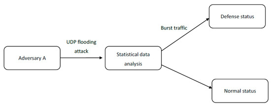
Figure 1.
Diagram of the proposed system.
The experiments were divided into two phases. The first considered a number of simple UDP packets transmitted to a switch, which may trigger a UDP flooding attack. Then, code execution was started on the simulated switch and controller, and the performance and security of the proposed defense mechanism were evaluated. Ryu is an SDN controller framework launched by the Japanese company NTT. It was developed on the basis of Python, with clear modules and good scalability. The software libraries and packages used in this experimental setting were the Ryu controller [12], OpenFlow version 1.3 [13], and Mininet [14].
3. Related Work
Recently, there have been numerous papers written on topics related to flooding attacks in SDN. Yan et al. have introduced various distributed denial-of-service (DDoS) attack methods in the cloud environment in recent years, and extensively explained various SDN defense mechanisms against DDoS. They conducted a comprehensive review of various DDoS attack mechanisms and SDN defense mechanisms [15]. Sathwara and Parekh introduced transmission-control-protocol (TCP) synchronous-flooding DDoS attack technology and a way to reduce its damage. The method involved finding out the attacker’s IP address and using TCP reset (RST) to limit subsequent attacks and allow legitimate customers to continue to connect to the server [16]. Ahmed and Kim discussed how SDN can mitigate DDoS attacks. Their approach relied on the use of traffic statistics on the switch to improve the accuracy of detecting DDoS [17]. Li et al. studied the impact of man-in-the-middle attacks on OpenFlow, and proposed a lightweight filter to find modified packets [18]. Moreover, Bawany et al. analyzed and classified various SDN DDoS attack and defense mechanisms, and developed an active DDoS defense framework. The goal was to protect security when building smart cities [19]. Mohammadi et al. proposed a defensive measure called SLICOTS to counter TCP synchronized-sequence-number (SYN) flood attacks. SLICOTS monitors TCP connection requests in the controller and prevents malicious hosts from connecting [20]. Abbasi et al. studied software-defined cloud computing (SDCC) and explained its main architectural components. Additionally, there are numerous opportunities and possible threats of SDCC in applications [21]. Ubale and Jain introduced various SDN vulnerabilities and various DDoS attack methods. They also described how SDN can overcome large-scale DDoS attacks, and proposed future technical trends to defend against such attacks [22]. Evmorfos et al. proposed a lightweight Internet detection technology to prevent common SYN attacks. In particular, they used deep-learning techniques to train with "normal" nonattack traffic, so that the neural network could recognize the traffic of SYN attacks [23]. In addition to the above, many studies related to the mechanism of SDN against flooding attacks have been conducted [24,25,26].
Phan and Park developed a solution to resist DDoS attacks in SDN cloud environments. Through support vector machines, they proposed a hybrid machine-learning model to classify network traffic, and used historical records to conduct network-traffic detection and IP filtering. They then combined the above to create a defense system [27]. Cui et al. used support vector machines to classify DDoS attack patterns. They also used cognition-inspired computing to develop a mechanism to detect and defend against DDoS attacks, in order to restore network communication to normal in real time [28]. Kansal and Dave proposed a mechanism that could attack an innocent third party, known as the moving-target defense mechanism. This also uses load-balancing algorithms to minimize the number of proxies used by the entire defense mechanism [29]. Wang et al. used the SDN architecture to design a defense mechanism against another type of DDoS, that is, link-flooding attacks (LFAs), and used multipath routing to reduce network congestion caused by LFAs [30]. Zhang et al. combined adaptive-correlation analysis and SDN to present a mechanism that could defend against multiple DDoS attacks. The scope of the defense includes SYN and UDP flood attacks. In this type of defense, there is no need for existing SDN protocols and switches for any upgrades [31].
On the basis of the consideration that enterprises can deploy defense mechanisms cheaply and quickly without changing existing protocols or improving the computing power, we propose two very simple and efficient methods. This is especially important for applications in the IoT field, where many devices have a limited computing power [7], since we only analyze the number of packets sent and received to find the ports that may be attacked. This information is easily available, so there is no need to make any changes to hardware and communication protocols. Among the above research results, some are schemes that require huge computing resources, such as the use of machine-learning models. Our method only requires a small number of programs to execute it, and uses very few computing resources, but when the machine is attacked by a UDP flooder, the defense effect is very good, so enterprises do not need to increase their computing resources.
4. Protocol Design and Experiments
This section first presents the idea of a simple UDP flooding attack. Then, it demonstrates how the proposed attack may successfully subvert SDN functionality. Lastly, different from the previous methods, we propose two lightweight defense measures that can effectively reduce the damage caused by UDP flood attacks. Some of the defense mechanisms we propose are the result of an extension of previous work [3].
4.1. Proposed Scheme #1
This section introduces the first proposed defense mechanism. First, the network-security level is detected by a defense mechanism. This means that the defense mechanism frequently sacrifices ARP requests so that it can activate the analysis mechanism, while continuing to monitor the current number of packets. The aim of this study was to preserve resources that may be attacked. Figure 2 presents a flowchart of the proposed defense mechanism. Figure 3 describes the internal system architecture, similar to [32]. Traffic monitoring is part of the control plane; it confirms the number of data packets returned by the switch, and the analysis module in the controller infrastructure then analyzes the number of data packets. If it is found to be attacked, it queries the flow table of the data plane to see if the address was recorded to determine which packets to drop. The controller infrastructure can also increase the flow rule in the flow table to increase addresses to be blocked. The packet content is also analyzed, as described in more detail in a later section.
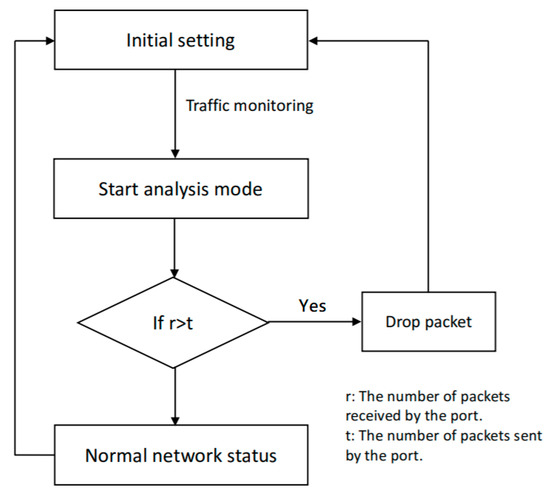
Figure 2.
Defense architecture flow chart [3].
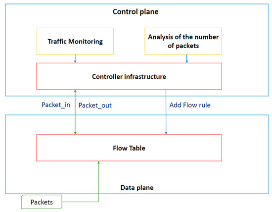
Figure 3.
Proposed architecture.
We now introduce the formation of ARP packets. Figure 4 illustrates how the ARP works. Suppose that Host A wants to transmit a packet to Host B. Host A checks whether there is a corresponding Host B media-access-control (MAC) address. If the address is not found, the ARP broadcasts packets to all hosts in the local area network (LAN). Each packet contains Host A’s MAC and IP addresses, and Host B’s MAC address to be queried. If a host is not found to correspond with the requirements, it refuses the ARP request. However, if a host finds a match, it responds to the message that contains the hardware address of Host B. Host A can then send a packet to Host B.
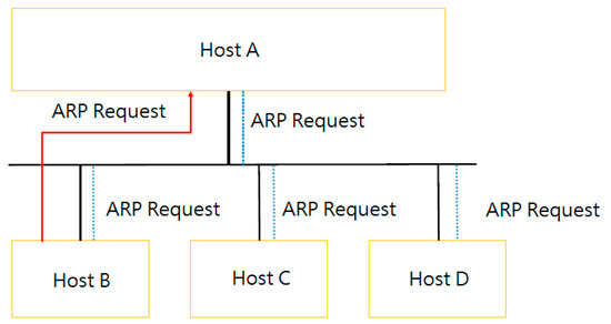
Figure 4.
Address-resolution-protocol (ARP) packet-transfer mode employed in this study.
After the network has run for a period of time and become stable, the procedure enters analysis mode, which can be thought of as a preprocessing phase of the proposed defense mechanism (which is explained in more detail later). A certain amount of time is sacrificed for all ARP request packets. The specific steps are shown as Algorithm 2:
| Algorithm 2. Defense mechanism. |
|
4.1.1. Received More Packages Than Sent Out
The flowchart in Figure 5 can be used to explain the first condition. Because the switch periodically returns the packet count to the controller, this count may show that the number of received packets is much greater than the number of sent packets. The meaning of this condition is that the current network does not include the destination of the sending packet, constantly leading to controller broadcasting. The network can then be exposed to attack; the countermeasure is to start dropping packets. Before dropping packets, the packets per second (pps) must be calculated. Then, the controller checks two conditions: The number of unknown destination addresses and the number of mismatches between a destination address and a flow-table entry. If both conditions are remarkably high, the switch starts to drop packets. Moreover, the controller adds another active flow rule, which indicates that a packet with an unknown destination address is not allowed to be forwarded to the controller. After this procedure has been running for some time, the network returns to its detection state. Before this occurs, however, the received/sent statistics for the number of packets in the port should be zero.
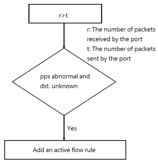
Figure 5.
When received packets (r) > sent packets (t).
Because the ARP packet-transmission rate is 500 pps in the Mininet environment, Mininet’s performance is unbalanced, which is equivalent to a network suffering from losses. Because Mininet was used in this research to create the network topology, the threshold for an abnormal pps rate was set to 500. From experimental data in FloodGuard [24], it is clear that 500 pps constitutes an attack. Because Mininet is a simulated environment, its bandwidth is the default value, and an unbalanced performance must be used to simulate a cyberattack. If the network bandwidth is variable, it can be followed to modify the defined abnormal value. In a real network, the measured port bandwidth can be calculated by using the following formula for the available pps: Mbps/8/(64+20 bytes), where 64 byte packets represent the smallest Ethernet unit and 20 bytes represent the general overhead. A condition exceeding the available pps is defined as abnormal.
4.1.2. Sent More Packages Than Received
The flowchart in Figure 6 can be used to explain the second condition. Because the switch periodically returns the packet to the controller to obtain the packet count, the packet count may reveal that the number of sent packets is much greater than the number of received packets. The meaning of this condition is that the current network includes the destination of the sending packet. In a sense, this indicates that the network is in a normal state. If the network has recently been attacked, the active flow rule must be updated so that packets with an unknown destination cannot be forwarded to the controller. Additionally, the controller has the ability to handle packet-in messages and broadcast packets. The network immediately changes to using the detection mechanism when suffering from an attack under normal conditions.
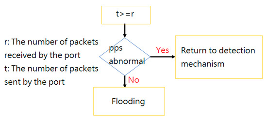
Figure 6.
When packets sent (t) > = packets received (r).
Figure 7 shows how to add a flow rule. The protected controller is no longer subject to vicious attack packets. Figure 6 only shows rules that were manually added. When the network is not under attack, the flow rule works by default; new flows are allowed to be sent to the controller. When an attack takes place, the packet destination address is unknown, and the packet cannot be sent to the controller. To stop attacks, the flow-table rules must be updated.
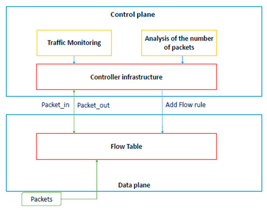
Figure 7.
Flowchart of how to add flow rules.
Figure 8 shows the flow-rule list. Rule 1 indicates that, when a new flow occurs, the default controller determines the flow. Rule 2 represents the response to an attack; it adds active flow rules so that, if the packet destination address is unknown, the packet is not allowed to query the controller. The next two rules indicate that this situation may occur. Rule 3 shows that packets from port2 can be directly forwarded to port3 without needing to ask the controller. Rule 4 shows that the packets from port4 are dropped for direct action.
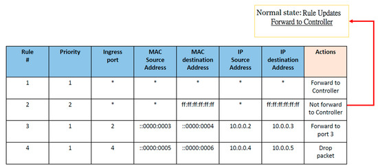
Figure 8.
List of flow rules in this study.
Algorithm 3 shows simple code implementation of the UDP defense mechanism. It shows the activation of the detection mechanism to check on network conditions. When entering the first condition, r > t, it checks the destination address. Conditions are reached to add to the active flow rules. The second condition, t ≥ r, serves to determine the pps rate. An SDN using this monitoring approach can repeatedly resist flooding attacks and maintain the performance. Next, we explain how the two conditions mentioned in the preceding paragraph are retrieved on the basis of required parameters r and t. Traffic monitoring regularly returns the number of packets. The number of intercepted packets received by all ports provides a value for r. The number of intercepted packets transmitted from all ports provides a value for t. In essence, information is retrieved when a decision needs to be made. The most important part of code implementation is traffic monitoring. A controller interval is set to monitor the number of incoming and outgoing packets. Whenever an abnormal number of packets is encountered, the controller can instantly detect the situation. In a word, the number of packets per second is used to differentiate between two conditions.
| Algorithm 3. User datagram protocol (UDP) Defense Section. |
|
4.1.3. Performance Analysis of Proposed Scheme #1
This subsection describes an analysis of the memory space needed by the defense-method program. Given the content of program (S), let M(S) be the total memory space required for the defense method, and let MF be a fixed memory-space requirement. On the other hand, MV (S), or the memory space needed to save the code, global variables, and constant, changes when the program is executed—its value changes. Therefore, the following formula for the memory required by the defense method can be stated as follows:
M(S) = MF + MV(S).
If a defense program occupies too much memory space, the defense effectiveness is poor. Because memory is needed to execute other applications, this results in an insufficient memory, poor performance, slow program-response speed, and lack of response to inputs. For a controller, this is unacceptable.
The next step is to analyze the communication overhead. For this, the packet-loss rate (Ploss) must be determined. Suppose that R is the total number of sent packets, T is the total number of received packets, and D is the difference between the two. The packet-loss rate can then be derived:
D = R − T,
Ploss = D/(R + T).
The packet-loss rate describes the effect of simply sending out packets, whether or not they are successfully received. Lastly, the packet throughput (TP) is determined to assess the network effectiveness. Let RT be the total number of received packets, and let N be the time it takes to receive a packet. The packet throughput can then be described as follows:
TP = RT/N.
The throughput and packet-loss rate can be used to represent the network status. A high packet-loss rate may be due to delay or network congestion. Low throughput is normally due to network congestion. Both of these are closely related, but either results in network-performance loss.
4.2. Experiments of Defense Architecture #1
4.2.1. Experimental Setting
In the experiments, Mininet was used to simulate SDN OpenFlow switch 1.3, and Ryu 3.7 was used to simulate the controller. IPerf, the top command, and IPTraf were used as monitoring tools [3]. Computers were used to simulate both entities. One of them used Mininet to generate a topology, and the other served as a controller to ensure that more accurate measurement occurred.
4.2.2. Results and Evaluation
In the experiments, two cases were considered, and differences between them were observed. The first case was a network under attack and the second case was a network working without any attack. In particular, in the first case, no defense mechanism was executed on the original Ryu controller, whereas in the second case, the proposed defense mechanism was activated. In both cases, UDP flooding attacks were launched over a period of time. Five minutes were required to simulate an attack. During the experiment, the monitoring software mentioned in Section 4.1 was used to collect network-performance statistics.
Figure 9 depicts the simulated network topology; only a simple network topology was simulated. Host 1 was responsible for launching UDP flooding, whereas the other hosts remained in normal operating mode [3].
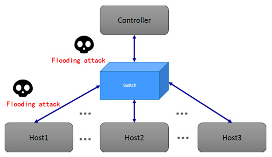
Figure 9.
Simulated software-defined networking (SDN) topology.
The experiment began by setting up a network with no defense mechanism. In this case, when there was no attack, the network bandwidth consumption was maintained at a certain level. In addition, the controller central processing unit (CPU) displayed no significant energy consumption. Then, Host 1 started UDP flooding. Table 1 shows the bandwidth-consumption figures for the two networks. Iperf represents the available bandwidth between the two virtual hosts; therefore, when the attack occurred, the available bandwidth of Iperf was reduced. Iptraf represents the controller bandwidth currently in use. In this case, Table 1 displays a rapid increase in the controller bandwidth, reaching almost 6000 KB/sec. The top command was used to monitor the CPU consumption. In the experiment, the controller’s CPU consumption began to slowly rise. Under normal circumstances, the bandwidth between virtual hosts is 51 GB/s. However, the bandwidth was reduced to 47 GB/s when the network was under attack. These data confirmed that, when the SDN network experiences a UDP flooding attack, not only is the bandwidth reduced, but the CPU consumption is also significantly increased and becomes a burden for the controller. If the attack keeps flooding the network, then the controller is eventually unable to function normally, resulting in a temporary shutdown of the entire network, which means that packets can no longer be processed, as illustrated in Table 1. In this experiment, uptime [33], which is a tool used to measure the controller load, was used. Table 2 shows the average load on the controller; a number much greater than one indicating an excessive load. The load is a measure of how busy the system’s CPU is and the number of processes that are waiting for the CPU scheduler. A length of one represents the length of the process currently waiting for CPU scheduling. Table 2 shows that, during the attack, the length reached 2.02. This means that the waiting process queue was at least twice as long as normal and completely full. Under these circumstances, the CPU became too busy, and incoming processes had to wait [3].

Table 1.
Network bandwidth and controller performance comparison [3].
Table 2.
Average load on the controller.
The next step was to carry out a UDP flooding attack. After the flooding attack was launched on the network with the proposed defense mechanism, the bandwidth was still increased, but only by 21.3 KB/sec. Moreover, the bandwidth between virtual hosts was still 50.3 GB/s. Having the defense in front of the network provided highly significant protection and greatly reduced the bandwidth consumption. In addition, the controller’s CPU consumption was also greatly reduced. The results of these two experiments confirmed that the proposed defense mechanism in the SDN network could effectively and significantly reduce the performance burden caused by UDP flooding attacks. Table 2 shows that the average load on the controller was less than one when the proposed defense mechanism was used.
The next step was to set up the defense mechanism. Measurements were performed under normal circumstances, and the results are shown in Table 3. The network bandwidth and controller CPU consumption were the same as those in the previous case. These measurements could be used to prove that adding the defense mechanism to the network enhances its security without imposing any additional costs. In addition to the expense of a request packet, Table 4 shows a comparison of delays before and after defense activation [3]. The numbers refer to the transmission time for sending the first packet to the host. Clearly, when the defense was not used, the delay time was 9.61 ms. After the defense was activated, the delay time was increased by only 0.40 ms, which is not too much.
Table 3.
Comparison of the normal network state. CPU, central processing unit.
Table 4.
Comparison of delays from the normal status and defense status.
The security benefits of the proposed defense mechanism were obtained by manipulating the SDN controller code. With the proposed method, no additional changes to the hardware device were needed. Moreover, the method is implementation-friendly, which means that the controller does not need to undergo significant changes to its core program to accommodate the proposed defense functionality.
Figure 10 shows a comparison of the CPU consumption before and after defense activation. At two seconds, the attack began. In one second, more than a thousand packets were transferred, and the CPU occupancy rate continually increased. However, once the defense had been activated, the CPU consumption quickly decreased again. Even at 10 s, it had returned to normal, with about 50 packets transferred per second. It is apparent that, in the normal state and with the defense running when under attack, the two losses did not differ much. With the defense running (blue line), in about eight or nine seconds, the CPU usage significantly dropped. This delay occurred because it was assumed that the system was determined to have been under attack before the analysis mechanism was activated. It is necessary to wait until after the analysis mechanism is activated to defend against the attack. If the analysis mechanism is activated while under attack, the waiting time does not have to be as long.
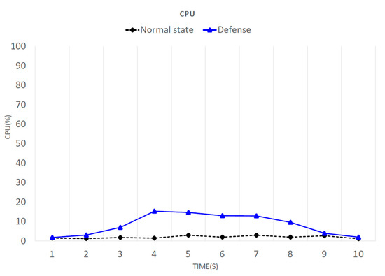
Figure 10.
CPU consumption.
Figure 11 shows a comparison of the bandwidth consumption before and after defense activation. Because Iperf was used to test the available bandwidth between virtual hosts, the network bandwidth varied according to its state at the time, possibly resulting in data fluctuations. However, this did not affect the experimental data. Next, the attack was observed. At two seconds after the attack had started, more than a thousand packets were transferred in one second, and the available bandwidth between virtual hosts was decreased. During the attack, the degree of bandwidth loss was very serious, but with the defense, the bandwidth was restored to close to normal, with about 50 packets transferred per second. Once the defense had been active (blue line) for eight or nine seconds, the available bandwidth increased. This delay occurred because it was assumed that the system was determined to have been under attack before the analysis mechanism was activated. It is necessary to wait until after the analysis mechanism is activated to defend against the attack. If the analysis mechanism is activated while under attack, the waiting time does not have to be as long.
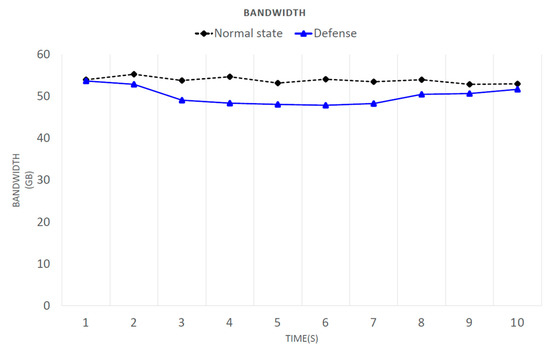
Figure 11.
Bandwidth consumption.
The top command was used to estimate the memory usage. Figure 12 shows that an increase in the number of switches did not cause a large memory increase, as stated in [34]. When a switch was added, the memory only slightly increased, which did not have much of an impact. When using the defense, the maximal increase in memory consumption was 0.062 GB.
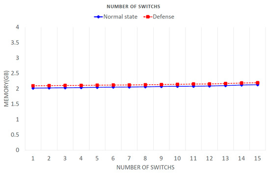
Figure 12.
Memory consumption.
Figure 13 shows the average execution time for the defensive methods. This figure shows the relationship between an increase in the number of switches and the average execution time. With an increase of five switches, the execution time increased by only one second. The proposed system added 15 switches, which involved an increase of only three seconds. This shows that any growth in execution time was not due to an increased number of switches.
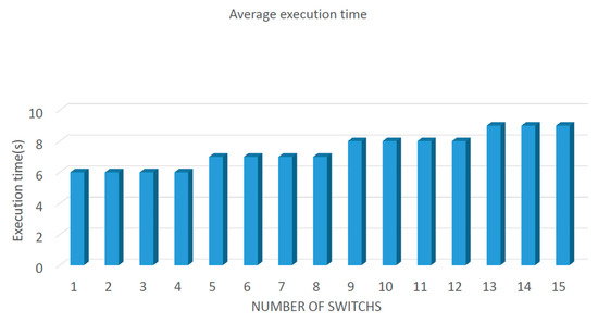
Figure 13.
Average execution time of defense Architecture#1.
Lastly, the results presented in this paper are listed, and the results from Section 2 are compared with those presented in [23,24]. AvantGuard [23] specifically considered SYN flooding. The authors in [24] stated that FloodGuard is resistant to all types of flooding attacks, but requires a large programming module, resulting in an overall delay increase. This is the main reason why this study particularly focused on UDP flooding attacks. This eliminated the need for complex packet-analysis modules, resulting in a decreased processing delay for packet transmission.
4.3. Proposed Architecture #2
This section proposes a different defense mechanism for UDP flooding attacks. A system-architecture diagram of this approach is presented in Figure 14. When a packet is sent to a switch and no match is found, a packet-in message is sent to the controller, and the monitoring of controller traffic begins. Switch-bandwidth traffic and the number of packets sent to the controller are determined. If a network attack is detected, the controller starts packet analysis. After packet analysis is complete, if a malicious packet is found, the controller triggers a defense reaction. Figure 15 shows a flowchart of the overall defensive architecture. Ryu was used to implement traffic monitoring in the switch. In this process, the controller gathers information from the switch, and after analyzing it, decides whether the network is under attack. If the network is found to be under attack, the number of abnormal packets in each port is counted. If a port receives too many abnormal packets, the packets from this port can be filtered. If the data-analysis results are normal, the traffic monitor continues to run.
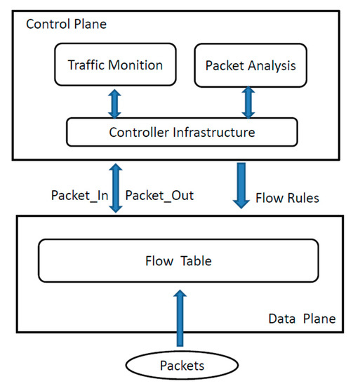
Figure 14.
Simple system architecture.
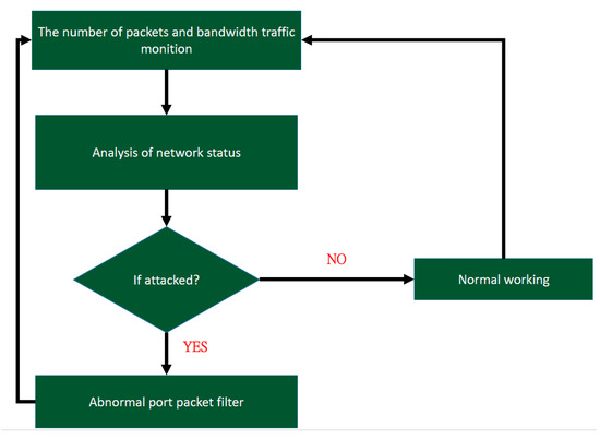
Figure 15.
Flowchart of the defense architecture.
4.3.1. Flooding-Attack Determination
How to determine whether a network is under attack still needs to be explained. When a network is under a UDP flooding attack, a large number of packets enter a particular switch. Because these packets do not require a link to be established, the network can continuously send packets, leading to a condition. These features are used to determine whether the network is under attack. This means that the following aspects of the network status must be checked:
- Whether the network is continuously broadcasting, and
- Whether a large number of packets are being sent to a particular switch and then forwarded to the controller.
First, the monitoring program mentioned earlier is used to monitor network traffic and determine the number of packets sent per second and port-traffic information. These data are used to analyze the current network status. The bandwidth is checked every second. If a significant increase in bandwidth occurs, then the bandwidth for each port is checked. When a broadcast message is sent, each port receives inquiries; therefore, the bandwidth of each port increases. If the network bandwidth increases very suddenly, and the bandwidth of each port is greater than or equal to the increase in the network bandwidth, then the current network is experiencing broadcasting. Algorithm 4 shows the code used to monitor the bandwidth. In this code, parameters rx bytes, tx bytes, rx band, and tx band are initialized to 0, where rx bytes, tx bytes, rx band, and tx band denote the received bytes, transmitted bytes, receiving bandwidth, and transmitting bandwidth from a given port, respectively. Traffic from each port is monitored, and the rx bytes, tx bytes, rx band, and tx band of each port are recorded, giving the traffic situation for the port.
| Algorithm 4. Bandwidth monitoring section code. |
|
Next, the number of received and forwarded packets from each switch is verified, and values are compared every second. If the number of ARP packets is greater than 500 packets per second, the performance of the Mininet switch starts to become abnormal. Because Mininet was used to build the SDN network, the threshold value in Mininet was set to 500. When the number of packets received per second exceeds the threshold value, this means that the network status is abnormal. However, the proposed defense mechanism subtracts 10% from the threshold to prevent a malicious attacker from using an attack rate close to, but less than, the threshold.
The next step is to discover abnormal ports and analyze the packets being sent through this port. This information is gathered to determine whether a UDP flooding attack is in progress. First, bandwidth monitoring is used to determine whether the network is broadcasting. The port that receives the minimal number of packets is known because the controller broadcasts a query message when it does not know the IP address of a packet, and all hosts in the network are asked. However, the controller does not query the port that sent the packet; therefore, this is the abnormal port. Then, the packets to and from this port are analyzed; packets are only analyzed when an abnormal port is found. The first step is to determine whether the packet is an ARP packet. If it is, the IP address records are stored in a table. When the next ARP packet is received, its IP address is compared with the records in the table. If the IP address is not in the table, it is also recorded in the table, and the count is increased by one. When the count exceeds the threshold of 500, it is determined that the port is under attack. Algorithm 5 presents the code used to analyze packet IP addresses.
| Algorithm 5. Analysis of packet IP addresses. |
|
4.3.2. Performance Analysis of Proposed Architecture #2
The advantages of SDN can be used to protect a network from an external attack. Because the SDN can issue rules governing the path of packets by means of the controller, the packet flow can be simply and easily changed. Hence, a rule can be automatically issued to drop ARP packets associated with the abnormal port. Lastly, when the network attack stops, the controller can be allowed to automatically modify the rules, and all packets can be sent to the switch. Algorithm 6 presents the code used to issue a rule to drop ARP packets from an abnormal port. The port number, packet type, and destination address are set, and nothing is done when a packet from the abnormal port is matched. The result is that all malicious packets are dropped. Figure 16 presents the procedure used to change the flow table [35]. Here, the default rules and the rules of the proposed defense measures are only briefly presented.
| Algorithm 6. Release rules used to block abnormal port packets. |
|
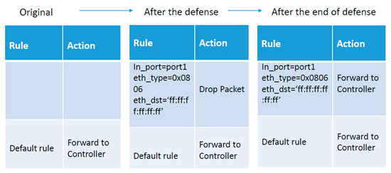
Figure 16.
Flow table change process.
4.4. Experiments of Defense Architecture #2
4.4.1. Experimental Setting
In the experiments, Python language was used to program an attack on the network. The Ryu 3.7 controller was chosen, and Mininet was used to simulate the SDN switch and the network infrastructure. Iperf, Iptraf, top, and Wireshark on Linux were also used.
4.4.2. Results and Evaluation
Next, the amount of time required for the defense mechanism to act is analyzed. The time taken to analyze a packet is P, the number of packets is S, and the time required to start the defense mechanism is PT. The required information is time PK until the number of packets exceed threshold S1. Suppose that the attacker sends N packets per second. Then, the time required to reach the threshold is S1/N. However, normal connection traffic sometimes exceeds the threshold for a short period of time [36]. To reduce the false-alarm rate of the proposed defense mechanism, the mechanism is only started when traffic on a port remains over the threshold for K seconds. With this information, the approximate time T required to start the proposed defense mechanism can be calculated as
T = PT + PK,
PT = S/P,
PK = (S1/N) + K,
K > = 1.
The proposed defense mechanism observes the network status and analyzes packets when the network status is abnormal. When N is large, the time taken to find the attack becomes shorter, but when S is large, the time taken to analyze the packets becomes longer, leading to a greater time requirement for the defense mechanism. The proposed method can adjust the parameters to achieve different required times according to the accuracy needed.
As mentioned earlier, when the SDN network is under attack, the controller bandwidth and performance are impacted. Hence, the proposed defense mechanism monitors both. The network-controller bandwidth and performance are first measured in a normal situation. Then, both are measured when the network is under attack without any defense mechanism. Lastly, both parameters are measured when the proposed defense mechanism is running to protect the network from attack. The results are then presented and compared. Table 5 presents the network bandwidth for three different situations, and shows that the proposed defense mechanism performed very well.
Table 5.
Bandwidth between switches and controllers.
The next step is to compare the bandwidth consumption between users. Table 6 shows that bandwidth was decreased by 7.7 Gbits/sec when the network was under attack without a defense mechanism. However, the bandwidth was decreased by only 0.4 Gbits/sec from the normal state when the network was under the protection of the proposed defense mechanism.
Table 6.
Bandwidth between hosts.
The controller performance must also be discussed. As mentioned earlier, when a large number of packets arrive at the controller for processing, the controller’s performance decreases as the number of packets increases. The controller becomes very busy, and delays start to occur during the packet-sending process. Table 7 presents CPU utilization in different situations. It is clear that the proposed defense mechanism reduces CPU utilization. In this study, Ping was used to perform a simple test on the delay time. The proposed defense mechanism significantly reduced the delay time, as shown in Table 7.
Table 7.
Performance comparison.
As shown earlier, the proposed defense mechanism was proven to be effective in defending against UDP flooding attacks. We assumed that an SDN network was operating stably and reliably, and compared two states of the normal network: The first without the proposed defense mechanism and the second with it. As shown in Table 8, under normal circumstances, the proposed defense mechanism does not affect the operation of the SDN network. After analysis, we found that, in the case of implementing a defense mechanism, the standard deviation of the experiment was 5.45 Kb/sec. If no defense mechanism was implemented, the standard deviation was 0.62 Kb/sec.
Table 8.
Differences for the added defense.
Lastly, the complete results are graphically displayed. As shown in Figure 17 and Figure 18, the bandwidth and CPU utilization were stable in the normal network.
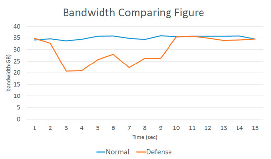
Figure 17.
Bandwidth comparison.
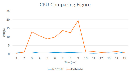
Figure 18.
CPU comparison.
The attack started at two seconds, and the bandwidth was significantly decreased because a large number of packets were entering. CPU utilization also started to increase at two seconds. However, after the proposed defense mechanism was activated, after nine seconds, the network state became stable again. This showed that the proposed defense mechanism needed only seven seconds to act. Figure 19 presents the amount of memory consumed by the controller to implement the proposed defense mechanism. It is clear that the additional memory consumption was slight.
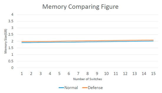
Figure 19.
Memory comparison.
Figure 20 depicts the time required to implement the proposed defense mechanism when the controller was controlling a large number of switches. When the number of switches exceeded a certain value, the required time increased because the switches needed to exchange traffic with each other. Hence, when the number of switches increased, the controller needed to increase the number of queries, and the execution time of the proposed defense mechanism increased.
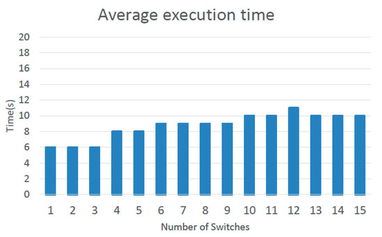
Figure 20.
Average execution time.
In conclusion, the proposed defense mechanism is easy to implement because it only needs to monitor the network and issue controller rules when needed. In these experiments, the proposed defense mechanism needed only seven seconds to complete its task. Packets from abnormal ports were simply blocked, and the delay incurred by normal packets was only 0.48 ms. This shows that the time cost of the proposed defense mechanism is slight.
4.5. Discussion
The proposed defense mechanism takes the approach of finding and blocking an abnormal port when a network is under a UDP flooding attack. Other normal ports can continue as usual. The traffic through each port is continually monitored. When the network is under attack, all ports except the abnormal port receive a large number of queries, but traffic in the abnormal port is less than that in the others.
However, special circumstances may occur. For example, during simultaneous attacks by Hosts 1 and 2, the attacker may deliberately send fewer packets from both hosts. We assumed that the sending rate was 300 packets/sec. Because the total number of packets entering the switch was greater than 500 packets per second in most cases, this attack was detected because traffic on the ports of Hosts 1 and 2 was very light. However, other hosts may send packets to Host 1. In this case, only Host 2 could be detected as launching an attack, and no defense rules were issued against Host 1. Nevertheless, it was discovered that Host 1 is launching an attack when other hosts stop sending packets to Host 1. In the worst circumstances, attackers could control other hosts, and keep sending packets to Host 1 to avoid defense mechanisms. In this case, the choice is made to ignore this attack because the attacker must limit the traffic from all hosts to fewer than 450 packets per second to avoid the proposed defense mechanism and allow the network to still work smoothly. All normal packets were also transmitted without difficulty; therefore, there was no need to start the defense mechanism.
5. Comparison with Other Results
Table 9 compares relevant methods [23,24] in terms of their simulated environmental settings. POX is an SDN controller framework launched by Nicira. It was developed in Python and plays an important role in SDN development. In the following discussion, the most relevant papers [23,24] are introduced in more detail.
Table 9.
Comparison with existing schemes [23,24]. TCP, transmission-control-protocol.
First, the difference between existing solutions to flooding attacks is described. AvantGuard [19] only considers TCP flooding. AvantGuard mimics the SYN proxy, intercepting the TCP handshake. The idea is to construct a virtual connection between the incoming connection host and a virtual host. AvantGuard was proven to be useful in defending against SYN flooding, but it incurs buffer saturation during an attack on an SDN switch [36]. In particular, two AvantGuard modules, known as connection migration and actuating triggers, are installed in the data plane. Afterwards, they perform TCP packet classification to determine whether packets are to be discarded, and they also perform preventive inspections.
FloodGuard [24] may also incur a buffer-saturation problem; packets forwarded to the SDN switch may be filled with random destinations. Therefore, they may saturate the switch-memory buffer. Even worse, this buffer-saturation problem can be created not only by filling in a fake address in the packet field, but also by filling in multiple fake addresses to enhance flooding. The defense in FloodGuard automatically installs flow rules and uses a migration agent to perform packet forwarding. FloodGuard was mainly designed to reduce the bandwidth loss between hosts.
Recall that the UDP flooding attack considered in this paper uses UDP packets whose destination IP is filled with a random value. The controller is thus faced with unnecessary processing, leading to a loss of bandwidth and even denial of service.
In this study, the proposed defense used traffic monitoring. More specifically, the controller worked as usual, except that it also used traffic monitoring to determine the network conditions, as described above. In other words, it determined whether each packet should be discarded or forwarded. The primary focus was on preserving the controller performance, even when the network was under a severe attack.
Table 10 presents a comparison of the two papers and the available bandwidth between hosts in each approach. In FloodGuard, the available bandwidth during the attack was completely consumed. Without using the defense system, the available bandwidth was consumed by the attacker by 1.7 Gb/sec. After the defense was activated, it consumed 0.05 Gb/sec of available bandwidth, accounting for 2.9% of the total bandwidth. In this study, the available bandwidth in a normal state was 51 Gb/sec. When the network was attacked, it was decreased by 4 Gb/sec, but when the defense was activated, the available bandwidth was still decreased by 0.7 Gb/sec, accounting for 1.4% of the total bandwidth. In both cases, when the defense was activated, the bandwidth consumption was significantly reduced. Nevertheless, FloodGuard’s symbolic execution engine needs to consume a certain amount of computing resources. It takes about ten seconds to activate the defense to operate, and offline preprocessing must be used to reduce the waiting time, but it cannot completely eliminate the waiting time. Compared with our lightweight defense mechanism, the complexity of the entire FloodGuard system is relatively high. The approach proposed here also has no time delay, and would therefore be better in this regard.
Table 10.
Comparison of different bandwidth methods.
The authors in [37] proposed a new soft-switch architecture. The new architecture could perform deep packet inspection and scan detection. Nevertheless, the main emphasis here is on the method proposed in [23,24].
6. Comparison of Two Kinds of Defense
This section describes a simple comparison of two defense methods. Experimental results are displayed in a table that presents the advantages and disadvantages of both, explaining the differences between them.
6.1. Defense Architecture #1
Our defense method can be described as follows: When starting a network, the current network-security status can be detected. Regardless of the current network conditions, a certain amount of time is sacrificed for all ARP request packets to prepare the analysis mechanism and to monitor the current number of packets at all times. The aim is to not miss any anomalies that may indicate an attack.
A certain amount of time is sacrificed for all ARP request packets. Packets are parsed and checked to see whether unknown destination addresses occur too frequently. If the answer is yes, the analysis mode is activated.
In attack mode, two conditions are checked: The number of unknown destination addresses and the number of mismatches between the destination address and flow-table entry. If both conditions are remarkably high, packets start to be dropped. Moreover, an additional active flow rule is activated, which indicates that packets with an unknown destination address are not allowed to be forwarded to the controller.
In a normal state, if the network was recently attacked, active flow rules must be updated so that packets with an unknown destination can again be forwarded to the controller. The network immediately activates the detection mechanism when an attack is detected under normal conditions.
The consumption costs of the above methods are analyzed as follows: Before entering analysis mode, a certain amount of time is sacrificed for all ARP request packets. When dropping packets, some benign requests are sacrificed. Benign requests generally need to wait for a short period of time, but this brings three benefits: (1) A periodic inspection of the network status is conducted, amounting to a network-security upgrade; (2) slightly higher legitimate traffic is not mistaken for an attack state; and (3) there is no delay time.
6.2. Defense Architecture #2
The defense method and principle of Architecture 2 are described as follows. The goal is to monitor the network at all times. In cases that do not require packets to be sacrificed, the defense detects network attacks and can determine the port in which incoming packets are abnormal, reducing the expense for normal port packets.
The first use of bandwidth traffic and the number of packets is to determine whether a network is under attack. Then, the abnormal port is identified, and abnormal port packets are analyzed to check whether an attack is underway. Lastly, SDN flow-table rules, which are automatic installation rules blocking packets to and from abnormal ports, are used.
The consumption costs of the above methods are analyzed as follows: A network attack is not immediately detected, but it is discovered by evaluating changes in the network. Networks need to sacrifice a certain amount of time to deal with attacks, but this brings benefits. When detecting the network state, to avoid sacrificing normal packets, we have to determine which port is being attacked and analyze its packets. This causes an approximately 5% increase in the delay time [36]. This is very small compared to the possible infinite delay brought about by an attack, but it does bring benefits. When blocking network attacks, packets traveling to the affected port are directly blocked, without affecting normal ports.
6.3. Consumption
This section presents comparative results for the two approaches and illustrates the differences between them. It is apparent that the performance improvements obtained from the two methods were largely the same.
Table 11 shows the experimental data for the two methods. On the CPU consumption side, after the two defenses were enabled, the CPU attrition rate was reduced to a normal level. As for first packet-transmission latency, the two methods did not differ very much, with a difference of about 1 ms. The bandwidth controller returned to a normal state after the defense was activated. The available bandwidth between the host and port also recovered to normal. Overall, the results for the two defense methods were not very different.
Table 11.
Comparison of two methods.
Next, differences between the two methods are highlighted. The first architecture, as mentioned, sometimes sacrifices ARP requests to achieve a high level of security. In the beginning, the network can be protected, but the performance may be sacrificed for benign requests. In the second architecture, although a certain amount of time must be sacrificed to deal with attacks before starting the defense, detecting the network state can prevent normal packets from being sacrificed. When blocking a network attack, packets for the affected port are directly blocked, without affecting normal ports. Hence, we can find that when Architecture #1 is implemented, the bandwidth of the controller and the decrease in CPU usage are relatively large. The reason for these differences is that benign packets are also dropped, which reduces the workload of the CPU. Similarly, the reduced number of packets also makes the bandwidth of the controller larger and the bandwidth consumed for communication between hosts is smaller. Besides, even if the network is not attacked, the defense mechanism of Architecture #1 will continue to check ARP request packets. Therefore, it can be found that when the network is not attacked, the CPU usage caused by the defense mechanism of Architecture #1 will be higher. However, overall, the performance of the two architectures is very close.
7. Validity and Its Threats
The above experimental results confirmed that the two defense structures that we proposed can effectively resist UDP flood attacks. Moreover, the defense mechanism consumes very few computing resources and little network traffic. However, this approach inevitably also causes some performance limitations. The first is that our defense mechanism refers to the flow table to determine which packets to drop. In this case, it is inevitable that some nonmalicious packets are dropped, so these packets must wait for the defense mechanism to be removed before they can be normally transmitted. Furthermore, the total number of transmitted packets in the entire network determines whether the defense mechanism is activated. We set an upper bound for the number of packets, and once the number of packets exceeded this upper bound, the defense mechanism was activated. However, it is not easy to set this upper bound. If it is set too high, an attacker launching an attack slightly below the upper limit may still consume a lot of computing and network resources. On the other hand, if the upper bound is set too low, it easily causes false alarms that interfere with the normal operation of the network.
In terms of the experiment, the real-time monitoring tools for network traffic that we used included Iperf and Iptraf. These are widely used in related experiments. However, Iperf is not very stable, and data fluctuations are relatively large and occur more frequently. It is necessary to lengthen the test time and increase the number of tests in order to obtain more accurate experimental results. As for the use of Iptraf, because it supports many network modes and is presented to the user in an interlaced manner, if the filter is not carefully set, the data about which we care may be missed.
In summary, we used two real-time monitoring tools for network traffic and conducted multiple experiments to improve the accuracy of our experimental results and find out the appropriate defense-mechanism settings.
8. Conclusions
This paper considered the problem of UDP flooding attacks on SDNs and pointed out the shortcomings of current SDNs. A simulated attack was conducted to prove that a UDP flooding attack could cause significantly increased controller CPU utilization. A set of defense mechanisms against UDP flooding was then proposed. The proposed defense mechanism resisted UDP flooding by means of minor modification in the SDN module. We monitored the flow of packets to determine whether the machine was under attack. Once the machine was attacked, we dropped suspicious packets through s comparison of the flow table. The number of packets represents data that can be easily obtained, so it does not significantly increase the burden on the CPU. The experimental results showed that the proposed methods could feasibly be used as an effective defense. Once the defense mechanism is implemented, the CPU usage, bandwidth consumption, and available bandwidth can all be very close to the situation before the attack. The consumption of computing and network resources was only increased by a few percentage points. Lastly, the study proved that the proposed method did not lead to substantial delay costs, whereas existing solutions lead to significant delays.
Author Contributions
Y.-H.T. and H.-C.W. designed and performed the experiments, derived the models, and analyzed the data. Y.-W.T. wrote the manuscript in consultation with Y.-T.T., N.S. and C.-M.Y. All authors have read and agreed to the published version of the manuscript.
Funding
This research received no external funding.
Conflicts of Interest
The authors declare no conflicts of interest.
References
- Greene, K. Software Defined Networking. Available online: http://www2.technologyreview.com/news/412194/tr10-software-defined-networking/ (accessed on 24 February 2009).
- Open Networking Foundation. OpenFlow Switch Specification. Available online: http://www.opennetworking.org/wp-content/uploads/2014/10/openflow-switch-v1.5.1.pdf (accessed on 26 March 2015).
- Wei, H.-C.; Tung, Y.-H.; Yu, C.-M. Counteracting UDP flooding attacks in SDN. In Proceedings of the 2016 IEEE NetSoft Conference and Workshops (NetSoft), Seoul, Korea, 6–10 June 2016; pp. 367–371. [Google Scholar]
- Di, A.; Ruisheng, S.; Lan, L.; Yueming, L. On the Large-Scale Traffic DDoS Threat of Space Backbone Network. In Proceedings of the 2019 IEEE 5th Intl Conference on Big Data Security on Cloud (BigDataSecurity), IEEE Intl Conference on High Performance and Smart Computing, (HPSC) and IEEE Intl Conference on Intelligent Data and Security (IDS), Washington, DC, USA, 27–29 May 2019; pp. 192–194. [Google Scholar]
- Mosenia, A.; Jha, N.K. A Comprehensive Study of Security of Internet-of-Things. IEEE Trans. Emerg. Top. Comput. 2017, 5, 586–602. [Google Scholar] [CrossRef]
- Ahmed, B.S.; Bures, M.; Frajtak, K.; Cerny, T. Aspects of Quality in Internet of Things (IoT) Solutions: A Systematic Mapping Study. IEEE Access 2019, 7, 13758–13780. [Google Scholar] [CrossRef]
- Hameed, S.; Khan, F.I.; Hameed, B. Understanding Security Requirements and Challenges in Internet of Things (IoT): A Review. J. Comput. Netw. Commun. 2019, 2019, 9629381. [Google Scholar] [CrossRef]
- Bures, M.; Cerny, T.; Ahmed, B.S. Internet of Things: Current Challenges in the Quality Assurance and Testing Methods. Lect. Notes Electr. Eng. 2018, 625–634. [Google Scholar] [CrossRef]
- Xu, R.; Ma, W.-L.; Zheng, W.-L. Defending against UDP Flooding by Negative Selection Algorithm Based on Eigenvalue Sets. In Proceedings of the 2009 Fifth International Conference on Information Assurance and Security, Xi’an, China, 18–20 August 2009; Volume 2, pp. 342–345. [Google Scholar]
- Shin, S.; Yegneswaran, V.; Porras, P.; Gu, G. AVANT-GUARD: Scalable and vigilant switch flow management in software-defined networks. In Proceedings of the ACM Conference on Computer and Communication Security, Berlin, Germany, 4–8 November 2013; pp. 413–424. [Google Scholar]
- Wang, H.; Xu, L.; Gu, G. FloodGuard: A DoS Attack Prevention Extension in Software-Defined Networks. In Proceedings of the 2015 45th Annual IEEE/IFIP International Conference on Dependable Systems and Networks, Rio de Janeiro, Brazil, 22–25 June 2015; pp. 239–250. [Google Scholar]
- Islam, T.; Islam, N.; Refat, A. Node to Node Performance Evaluation through RYU SDN Controller. Wirel. Pers. Commun. 2020, 1. [Google Scholar] [CrossRef]
- Ryu/OpenFlow How to Map in_Port Number to Physical Port. Available online: https://stackoverflow.com/questions/60939750/ryu-openflow-how-to-map-in-port-number-to-physical-port (accessed on 31 March 2020).
- Mininet. Available online: mininet.org (accessed on 15 January 2015).
- Yan, Q.; Yu, F.R.; Gong, Q.; Li, J.; Yu, R. Software-Defined Networking (SDN) and Distributed Denial of Service (DDoS) Attacks in Cloud Computing Environments: A Survey, Some Research Issues, and Challenges. IEEE Commun. Surv. Tutorials 2016, 18, 602–622. [Google Scholar] [CrossRef]
- Sathwara, S.; Parekh, C. Distributed Denial of Service Attacks—TCP Syn Flooding Attack Mitigation. Int. J. Adv. Res. Comput. Sci. 2017, 8, 2392–2396. [Google Scholar]
- Ahmed, M.E.; Kim, H. DDoS Attack Mitigation in Internet of Things Using Software Defined Networking. In Proceedings of the 2017 IEEE Third International Conference on Big Data Computing Service and Applications (BigDataService), San Francisco, CA, USA, 6–9 April 2017; pp. 271–276. [Google Scholar]
- Li, C.; Qin, Z.; Novak, E.; Li, Q. Securing SDN Infrastructure of IoT–Fog Networks from MitM Attacks. IEEE Internet Things J. 2017, 4, 1156–1164. [Google Scholar] [CrossRef]
- Bawany, N.; Shamsi, J.A.; Salah, K. DDoS Attack Detection and Mitigation Using SDN: Methods, Practices, and Solutions. Arab. J. Sci. Eng. 2017, 42, 425–441. [Google Scholar] [CrossRef]
- Mohammadi, R.; Javidan, R.; Conti, M. Slicots: An sdn-based light weight countermeasure for tcp syn flooding attacks. IEEE Trans. Netw. Serv. Manag. 2017, 14, 487–497. [Google Scholar] [CrossRef]
- Abbasi, A.A.; Abbasi, A.; Shamshirband, S.; Chronopoulos, A.T.; Persico, V.; Pescape, A.; Pescaph, A. Software-Defined Cloud Computing: A Systematic Review on Latest Trends and Developments. IEEE Access 2019, 7, 93294–93314. [Google Scholar] [CrossRef]
- Ubale, T.; Jain, A.K. Survey on DDoS Attack Techniques and Solutions in Software-Defined Network; Springer International Publishing: Cham, Switzerland, 2020; pp. 389–419. [Google Scholar]
- Dainotti, A.; Pescapè, A.; Ventre, G. Worm Traffic Analysis and Characterization. In Proceedings of the 2007 IEEE International Conference on Communications, Glasgow, Scotland, 24–28 June 2007; pp. 1435–1442. [Google Scholar]
- Aceto, G.; Pescapè, A. Internet Censorship detection: A survey. Comput. Netw. 2015, 83, 381–421. [Google Scholar] [CrossRef]
- Evmorfos, S.; Vlachodimitropoulos, G.; Bakalos, N.; Gelenbe, E. Neural network architectures for the detection of SYN flood attacks in IoT systems. In Proceedings of the 13th ACM International Conference on PErvasive Technologies Related to Assistive Environments, Corfu Island, Greece, 30 June–3 July 2020; pp. 1–4. [Google Scholar]
- Megyesi, P.; Botta, A.; Aceto, G.; Pescapé, A.; Molnár, S. Challenges and solution for measuring available bandwidth in software defined networks. Comput. Commun. 2017, 99, 48–61. [Google Scholar] [CrossRef]
- Phan, T.V.; Park, M. Efficient Distributed Denial-of-Service Attack Defense in SDN-Based Cloud. IEEE Access 2019, 7, 18701–18714. [Google Scholar] [CrossRef]
- Cui, J.; Wang, M.; Luo, Y.; Zhong, H. DDoS detection and defense mechanism based on cognitive-inspired computing in SDN. Futur. Gener. Comput. Syst. 2019, 97, 275–283. [Google Scholar] [CrossRef]
- Kansal, V.; Dave, M. DDoS attack isolation using moving target defense. In Proceedings of the 2017 International Conference on Computing, Communication and Automation (ICCCA), Greater Noida, India, 5–6 May 2017; pp. 511–514. [Google Scholar]
- Wang, J.; Wen, R.; Li, J.; Fei, Y.; Zhao, B.; Yu, F. Detecting and Mitigating Target Link-Flooding Attacks Using SDN. IEEE Trans. Dependable Secur. Comput. 2019, 16, 944–956. [Google Scholar] [CrossRef]
- Zheng, J.; Li, Q.; Gu, G.; Cao, J.; Yau, D.K.Y.; Wu, J. Realtime DDoS Defense Using COTS SDN Switches via Adaptive Correlation Analysis. IEEE Trans. Inf. Forensics Secur. 2018, 13, 1838–1853. [Google Scholar] [CrossRef]
- Wang, M.; Zhou, H.; Chen, J.; Tong, B. An Approach for Protecting the OpenFlow Switch from the Saturation Attack. In Proceedings of the 2015 4th National Conference on Electrical, Electronics and Computer Engineering, Xi’an, China, 12–13 December 2015; pp. 729–734. [Google Scholar]
- Everything You Need to Know about Web Hosting Uptime. Available online: https://www.quicksprout.com/web-hosting-uptime/ (accessed on 24 October 2019).
- Padekar, H.; Park, Y.; Hu, H.; Chang, S.-Y. Enabling Dynamic Access Control for Controller Applications in Software-Defined Networks. In Proceedings of the 21st ACM on Symposium on Access Control Models and Technologies, Shanghai, China, 6–8 June 2016; pp. 51–61. [Google Scholar]
- Ambrosin, M.; Conti, M.; De Gaspari, F.; Poovendran, R. LineSwitch: Efficiently Managing Switch Flow in Software-Defined Networking while Effectively Tackling DoS Attacks. In Proceedings of the 10th ACM Symposium on Information, Computer and Communications Security, Singapore, 14–17 April 2015; pp. 639–644. [Google Scholar]
- Glisic, S.; Makela, J.-P. Advanced Wireless Networks: 4G Technologies. In Proceedings of the 2006 IEEE Ninth International Symposium on Spread Spectrum Techniques and Applications, Manaus-Amazon, Brazil, 28–31 August 2006. [Google Scholar]
- Park, T.; Kim, Y.; Shin, S. UNISAFE: A Union of Security Actions for Software Switches. In Proceedings of the 2016 ACM International Workshop on Security in Software Defined Networks & Network Function Virtualization, New Orleans, LA, USA, 11 March 2016; pp. 13–18. [Google Scholar]


© 2020 by the authors. Licensee MDPI, Basel, Switzerland. This article is an open access article distributed under the terms and conditions of the Creative Commons Attribution (CC BY) license (http://creativecommons.org/licenses/by/4.0/).