Article

Design of MIMO Antenna with an Enhanced Isolation Technique

1
School of Electrical and Electronic Engineering, North China Electric Power University, Beijing 102206, China
2
School of Control and Computer Engineering, North China Electric Power University, Beijing 102206, China
3
Department of Electrical Power and Machines, Faculty of Engineering, Cairo University, Giza 12613, Egypt
*
Authors to whom correspondence should be addressed.
Electronics 2020, 9(8), 1217; https://doi.org/10.3390/electronics9081217
Submission received: 30 June 2020 / Revised: 21 July 2020 / Accepted: 24 July 2020 / Published: 28 July 2020
(This article belongs to the Special Issue Antennas for Next-Generation Communication Systems)

Abstract

:
The isolation between the microstrip patches has a great significance to examine the performance of the multiple-input-multiple-output (MIMO) antennas. The patch antennas are placed on the top of 1.46 mm thick Rogers RO3003 substrate having a length of 60 mm, a width of 50 mm, and relative permittivity of 3. The distance between the resonators is 0.06λ and they are stimulated by two coaxial probes extended from the bottom ground layer. The defective ground structure of the H-shape slot is inserted on the bottom ground layer to achieve high isolation (mutual coupling reduction). The proposed MIMO antenna operates at 5.3 GHz frequency, which can be used for WiMAX, Wi-Fi, and future 5G services all over the world. The results of the designed structure have been simulated in a finite element method-based solver high-frequency structure simulator (HFSS). The simulated results show that the reflection coefficient (S11) and isolation (S21) at the desired frequency are −32 dB and −41 dB, respectively.

1. Introduction

With the fast speed development experienced in wireless communication technology, there is an ever-increasing requirement for the high performance of moveable handheld applications, which mainly comprise very high data rates. An upcoming generational telecommunication standard, 5G, is projected to have data rates of 10 megabits per second up to 10 gigabits [1,2]. Microwave is a wide term that covers the ultra high frequency (UHF) with a range of frequency between 300 MHz and 3000 MHz to the extremely high frequency (EHF) with a range of frequency from 30 GHz to 300 GHz. The unlicensed wireless Ethernet links and licensed microwave bridges usually operate in the super high frequency (SHF) with frequencies between 3 GHz to 30 GHz and the EHF bands. The general fact is that the signal will travel having a low frequency. Consequently, at lower frequencies, the throughput is lower and vice versa. The link of the frequencies of licensed microwaves used for wireless backhaul networking a point to point connection works at 6 GHz, 11 GHz, 18 GHz, and 23 GHz bands. Meanwhile, the E-band wave for the above wireless backhaul communication works at an 80 GHz millimeter wave. On the other hand, the unlicensed wireless Ethernet bridges are utilized in point to point wireless links, point to multipoint wireless links, or wireless mesh topologies. Typically, they operate in the range of 0.9 GHz, 2.4 GHz, 5.3 GHz, 5.4 GHz, or 5.8 GHz frequencies. The popular choice for the outdoor wireless backhauls is to use unlicensed wireless Ethernet bridges of microwave communication. The unlicensed band of 5 GHz (5.3 GHz, 5.4 GHz, and 5.8 GHz band) became the most important selection by several end-users and outdoor wireless installation, because of their flexibility, cost-effectiveness, and quick consumptions.
For the transmission of a high data rate, the MIMO system was introduced in the recent past years. The MIMO antenna is the combination of two or more antenna elements that are used simultaneously for transmission as well as for reception over a radio channel. Meanwhile, the mutual coupling is the major problem that occurred in the MIMO antenna, which decreases the effectiveness of the antenna and has a negative effect on the execution of the MIMO antenna. The researchers proposed and developed many techniques for the reduction of mutual couplings, such as electromagnetic bandgap (EBG) structure, resonator, placing MIMO antenna in orthogonal position, [3,4], etc. Through the suppression of surface-wave, the coupling between antennas can be deceased by EBGs, and the mushroom-like EBG configuration is placed between antenna elements to decrease the mutual coupling of microstrip MIMO antennas [3,5]. Inserting a parasitic element also is another technique that has been used to achieve high isolation between closely spaced array elements. The parasitic structure is generally placed between the two elements to decrease the plane current. However, this technique affects the matching level of the general system, and that amplified the complexity of the design by adding an exterior matching circuit [6,7]. Furthermore, differential feeding technique is also utilized to achieve high isolation in MIMO antennas without inserting any element in the ground plane, or any part of the system needs to place the antenna in the opposite direction. In this technique, each port consists of a dual-element subarray with two subarrays interlaced [8]. There are also many other decoupling methods used for the reduction of mutual couplings, such as decoupling networks [9,10], neutralization lines [11,12], ground plane medications [13,14], metasurface structures or frequency selective surfaces [15,16]. In [17], the authors achieved enhanced isolation by putting a rectangular stub between the two patches. Other procedures to increase isolation between the patches is to launch a reactor of a T-shaped [18], meandered line resonator in [19], different elements for polarization diversity in [20], using electromagnetic bandgap (EBG) structures [21], defective ground structure [22], and a perpendicular feeding system in [23]. In [24], the mutual coupling is decreased by using parasitic-piece-type elements between the MIMO antenna radiators.
Besides this, one of the recognized methods to decrease the mutual coupling is to use the defected ground structure (DGS) where slots are placed in the general ground between the closely spaced antennas. This technique is enough for isolation purposes, where the front-to-back ratio is not judged as the slots could be a source of the undesired back radiation [25].
The main contributions of this research work are summarized below:
  • Different DGS structures are proposed to obtain mutual coupling reduction between two circular patches. These structures, which are closely placed to each other on top of the substrate, operate at a frequency of 5.3 GHz which is better than 4.8 GHz [26].
  • In this work, circular patches are used instead of rectangular patches because circular resonators provide better performance in terms of S-parameters, voltage standing wave ratio (VSWR), and other parameters [27].
  • A novel approach is implemented on different DGS shapes (the ground is cut off in I-shaped, T-shaped, and H-shaped) to get less return loss (S11) and insertion loss (S21) which results in −32 dB and −41 dB, respectively. The reduction in the insertion loss is better than previous work (e.g., [12,28]). A compact MIMO antenna is presented with high isolation between the MIMO radiating elements (S21/S12 < −41 dB).
  • The proposed H-shape MIMO antenna has a better gain performance compared to previous work (e.g., [29,30]). Additionally, the envelope correlation coefficient (ECC) and diversity gain are utilized to evaluate antennas for the first time to check the performance along with efficiency, directivity, and gain.
  • The feeding scheme for the two patches is coaxial probes extended from the bottom ground layer. This scheme is easily implemented due to less spurious radiation effects as compared with [31]. Meanwhile, to obtain impedance matching this method can be placed at any desired position inside the patch.
The designed antenna is the best candidate for the 5G and WIFI devices because of its very high mutual-decoupling between the antenna elements. Low ECC, high efficiency, and high gain. This paper is divided into six main sections. Section 2 defines the antenna characterization while Section 3 presents the simulation results. In Section 4, the given MIMO antenna performance is analyzed. Comparisons of the proposed technique and the previous works are investigated in Section 5. Finally, the conclusion is discussed in Section 6.

2. Proposed Model Design and Analysis

This section describes how to design and analyze the proposed MIMO antenna model, the antenna design is first designed. Then, the evolution process is analyzed.

2.1. Antenna Design

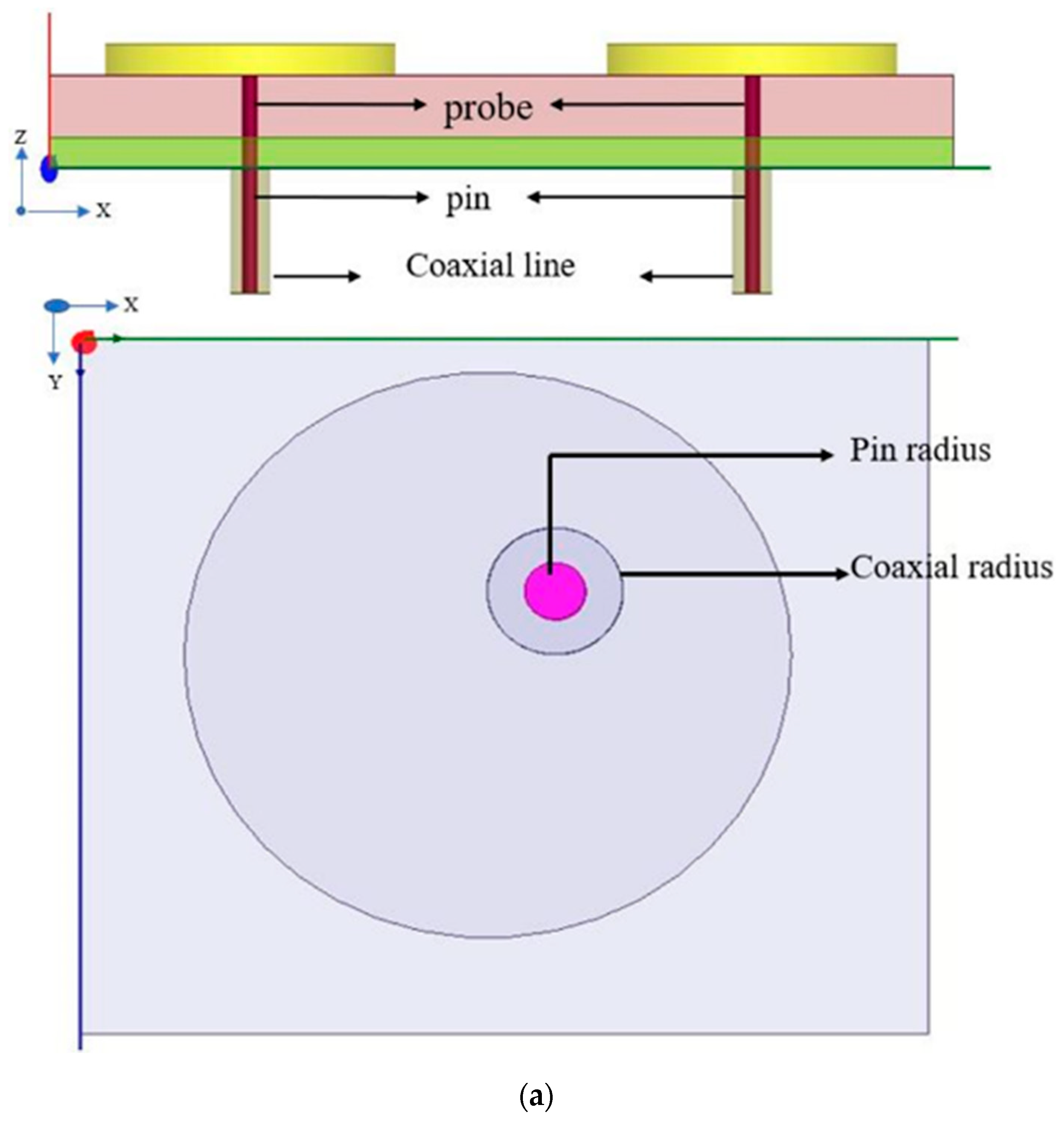
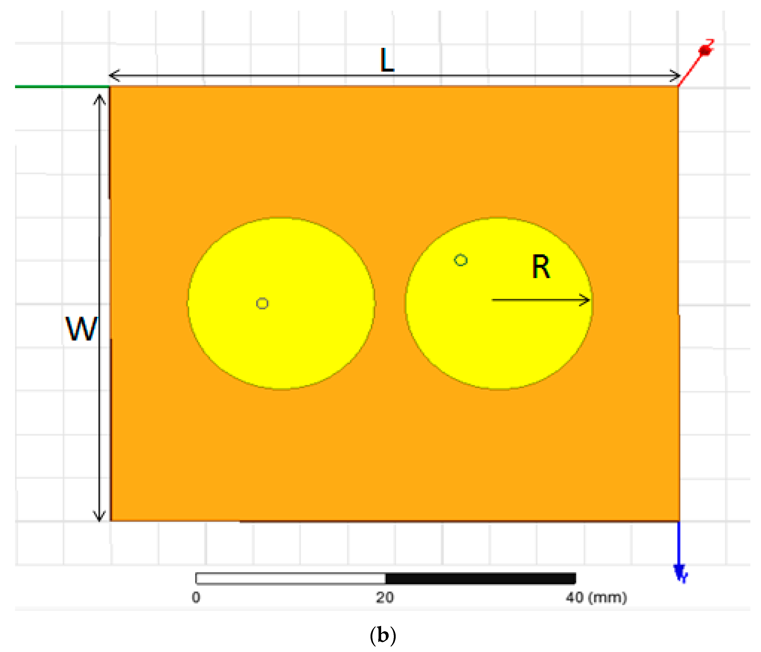
The geometry and arrangement of the given MIMO antenna are given in Figure 1. A circular resonator antenna with a radius of 9 mm is placed on the top of 1.46 mm thick Rogers RO3003 substrate having a length of 60 mm, a width of 50 mm, and relative permittivity of three and the ground plane is designed on the bottom of the substrate. A radiating element is agitated by the coaxial feeding technique. The coaxial feeding technique consists of a pin, probe, and coaxial. The probe height is 1.46 mm from the ground plane to the patch, and similarly, the pin height is 3 mm below the ground plane in opposite direction to the probe, while the length of the coaxial is same like pin and also in the same direction, but the only difference is the radius, we have taken radius of the coaxial according to ground cut off means 1 mm and below feeding point port is placed radius of 1 mm. One thing that should be noted first is that we need to cut off the ground according to the coaxial feeding radius means the radius of the coaxial.
However, the suggested design has only a relation to the isolation of the antenna array. Further, the proposed antenna also provides desirable gain, reliable efficiency, which are the important parameters for any antenna array. Table 1 charts the advanced parameters of the given MIMO antenna.
A second patch of the same shape and size is placed close to the first one, as displayed in Figure 2. One is having a mutual ground plane. Greater space for enhanced isolation between the patches is achieved by using a circular-shaped antenna array instead of the conventional rectangular radiators. The elements of each antenna in the MIMO system are fed with a 50 Ω microstrip feed line in order to get perfect impedance matching.

2.2. Evolution Process

In the proposed model, Figure 2 presents the front outlook of the given MIMO antenna while Figure 3a–d shows the process of evolution in the ground surface of the given antenna array. In the first step, two simple circular-shaped patches were designed and experienced for the desired results (Antenna-1), and then it is modified to I-shaped DGS for better MIMO performance (Antenna-2). Figure 3a,b shows a simulated reflection coefficient (S11) and mutual coupling reduction (S21) of the given antenna for the simple ground plane and ground plane with differently-shaped DGS. It should be noted that high isolation is always enviable for high-performance MIMO antennas. It is observed that Antenna-1 is not operating at the given frequency when the usual ground plane is used. The isolation between the proposed antennas is increased by varying the ground plane. To get proper operation of the MIMO antenna, which can be achieved by putting an I-shaped DGS on the plane used in the designing of Antenna-2, is varied and promotes T-shaped DGS to further reduce mutual coupling between the MIMO antennas as evident from Figure 3a–c.
High isolation between two patches is obtained by producing H-shaped DGS in the ground plane. An H-shaped DGS is utilized in the designed antenna for a specific purpose. It increases the isolation between the antenna arrays by acting as reactors to distinct the radiation of the arrays. As shown in Figure 3, more than 41 dB of mutual coupling reduction is produced at 5.3 GHz by placing an H-shaped DGS in the ground plane. Similarly, for better performance of the antenna, it must need to have a better return loss (S11) value which is 31 dB in this design. In Table 2, a lot of comparisons of the proposed design with the previous designs provide the superiority of the given antenna design.

3. Simulation Results

The results of the proposed antenna have been simulated in a finite element method-based solver high-frequency structure simulator (HFSS). The simulation results are presented in the following five sections. All the following simulations are achieved using a finite element modeling (FEM) based high-frequency structure simulator (HFSS) ver. 15.0.3 environment with a hardware platform of Intel i7-7700 CPU, 3.60 GHz, 16.0 GB RAM, and personal computer. This HFSS software has been used for simulating and optimizing the proposed antenna design. The analytic solving method is the method of moments (MoM). Meanwhile, for meshing, the auto mesh method in HFSS has been utilized.

3.1. S-Parameters

Two Circular patches are placed on a commercially available substrate of Rogers RO3003 having a dielectric constant of three and height 1.46 mm. Return Loss and Insertion Loss S11 is the return loss (represents the number of radiations bounce back from the antenna), also known as the reflection coefficient, while S21 is the insertion loss or isolation (represents the power received at antenna two relative to the power input to Antenna-1 in MIMO antenna) before decoupling. The simulated S11 result of the given MIMO antenna while using H-shaped DGS in the ground at 5.3 GHz is less than −32 dB.
The decoupling parameter S21 of the designed MIMO antenna is less than −41 dB at frequency 5.3 GHz. The S11 parameter and S21 parameter of the simulated MIMO antenna are illustrated in Figure 4, respectively.

3.2. Voltage Standing Wave Ratio

Voltage standing wave ratio (VSWR) is the amount of mismatch of a line and it is an important part S11 parameter in antenna system the appropriate value of VSWR for an antenna is between one and two.
In Figure 5, the results show that VSWR of Antenna-1 is about three which is not ideal value for an antenna, as we are doing variation in the ground field the value of VSWR gets better. The VSWR value of Antenna-2 is more than five which is also not appropriate for antenna performance. Consequently, the value of Antenna-3 is two, which is not suitable, and the value of VSWR of Antenna-4 is 1.34, which is ideal for communication.

3.3. Antenna Gain

An antenna’s gain is a key parameter that unites the antenna‘s directivity and efficiency. It is the directionality of an antenna; if the gain of the antenna in a specific direction is high it means the antenna works properly.
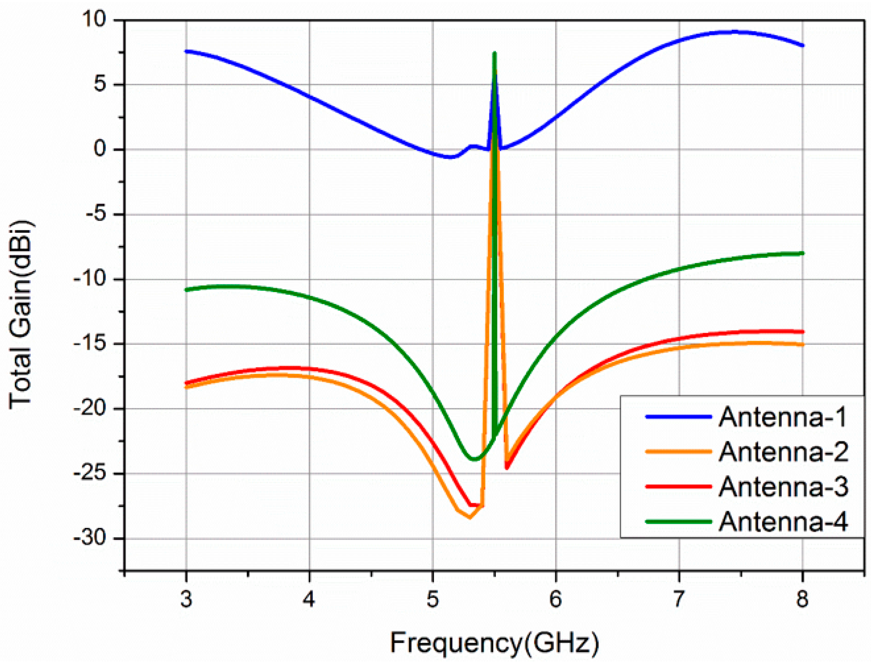
In Figure 6, the total gain of Antenna-1, Antenna-2, Antenna-3, and Antenna-4 is approximately 7.88 dBi, 6.65 dBi, 6.84 dBi, and 8.4 dBi at 5.3 GHz, respectively.

3.4. Directivity

Directivity is also another parameter in terms of the antenna and defined as the amount of the radiation intensity in the proposed direction to its average in the overall directions, it is also similar to gain means that if directivity is high then the antenna will work properly. The directivity of MIMO Antenna-1, Antenna-2, Antenna-3, and Antenna-4 is approximately 8.0 dBi, 6.78 dBi, 6.95 dBi, and 8.4 dBi at 5.3 GHz, respectively, as shown in Figure 7.

3.5. Radiation Pattern

Radiation patterns of Antenna-1, Antenna-2, Antenna-3, and Antenna-4 are shown in Figure 8a–d, respectively.

3.6. Surface Current Distribution

The given MIMO antenna array performance is further examined by designing surface current distribution with a modified ground plane (introduction of different DGS-shaped) at 5.3 GHz. The current distribution of the surface in the given MIMO antenna is displayed in Figure 9a when Port 1 is electrified, low isolation is accomplished between the antenna arrays as the current is highly coupled with another patch, as shown in Figure 9a isolation is increased by digging I-shaped DGS in the ground surface but still enough current is overlapped with the second patch as shown in Figure 9b and the implementation of the given MIMO antenna was improper-shaped DGS is placed in the ground plane to further decrease the mutual coupling reduction between elements of the MIMO antenna but still some current was passing through the channel as shown in Figure 9c.
H-shaped DGS is placed in the ground plane to decrease the mutual coupling between MIMO antenna elements further. Very less current is overlapped with the other patch, and hence greater isolation is achieved between the antennas by introducing H-shaped DGS in the ground plane as shown in Figure 9d.

4. Proposed MIMO Antenna Performance

The performance of the proposed MIMO antenna is validated by utilizing diversity analysis. This analysis is performed by using two parameters i.e., the diversity gain (DG) and envelope correlation coefficient (ECC).

4.1. Diversity Analysis

The diversity analysis of the given antenna is presented in the following sections.

4.1.1. Envelope Correlation Coefficient

To authorize the performance and competence of the given MIMO antenna array, it is essential to have an ECC. The ECC can be calculated using S-parameters by the following equation [28].
E C C = | S 11 × S 12 + S 21 × S 22 | ( 1 | S 11 | 2 | S 12 | 2 ) ( 1 | S 21 | 2 | S 22 | 2 )
The efficiency of an antenna is a number between 0 and 1 being ratio. However, antenna efficiency is usually found in terms of a percentage; for example, an efficiency of 0.5 means 50% efficiency. The efficiency of the given MIMO antenna is shown in Figure 10 which is 98.01% at 5.3 GHz.

4.1.2. Diversity Gain

The effects of diversity are usually achieved when transmitters receive multiple forms of the transmission stream over different channel paths.
It is supposed as the difference between the time average SNR in the combined signal in a MIMO antenna and the individual antenna system in a single antenna, where the SNR is higher than the standard reference level [32].
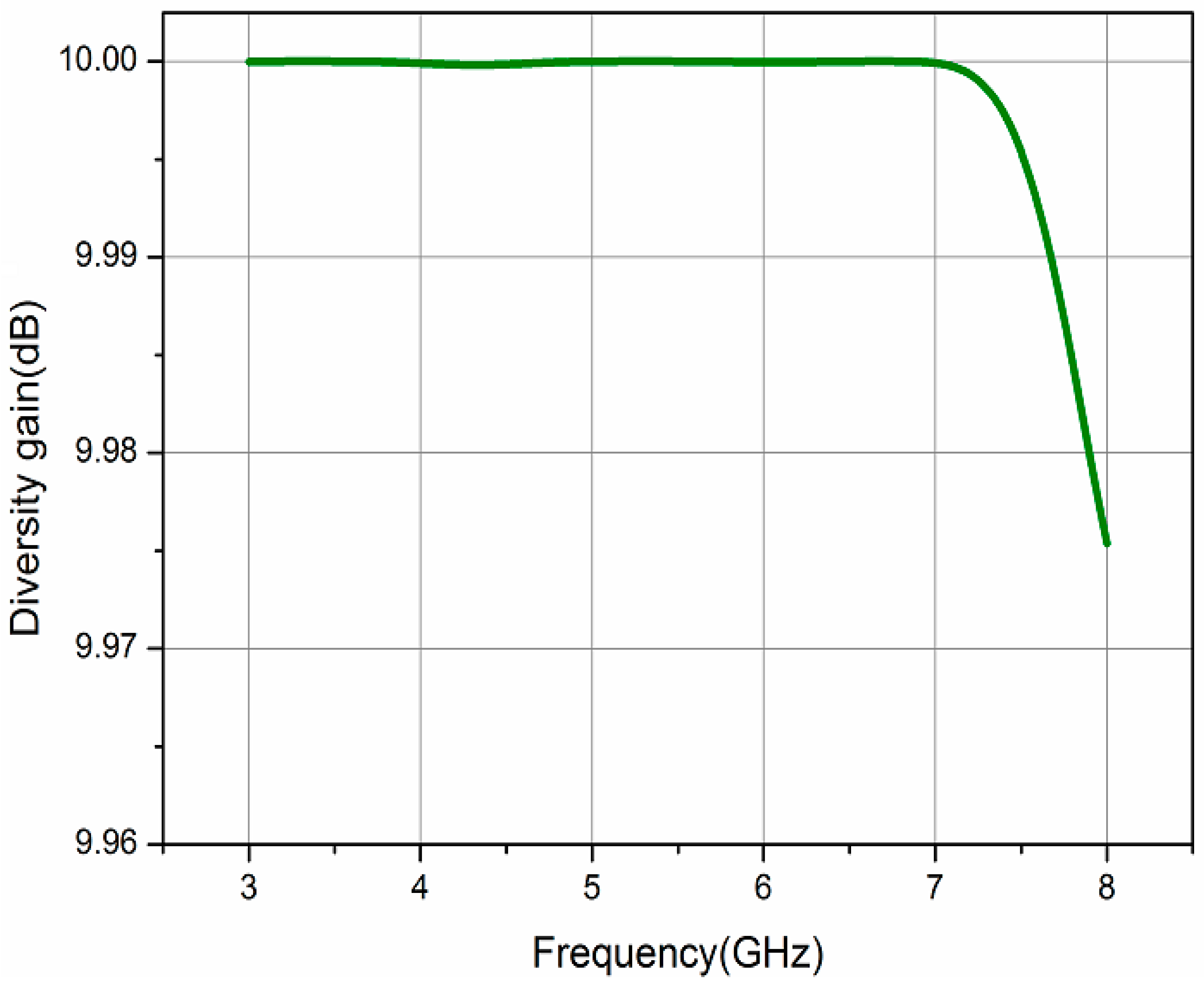
From the envelope correlation coefficient, the value of diversity gain can be calculated as:
D G = 10 1 ( E C C )
where ECC refers to the envelope correlation coefficient and DG refers to diversity gain. The simulated diversity gain of the proposed antenna is also shown in Figure 11 which is almost 10 dB.

4.2. Total Active Reflective Coefficient

In terms of the S-parameter, the total active reflective coefficient is evaluated by using the equation is:
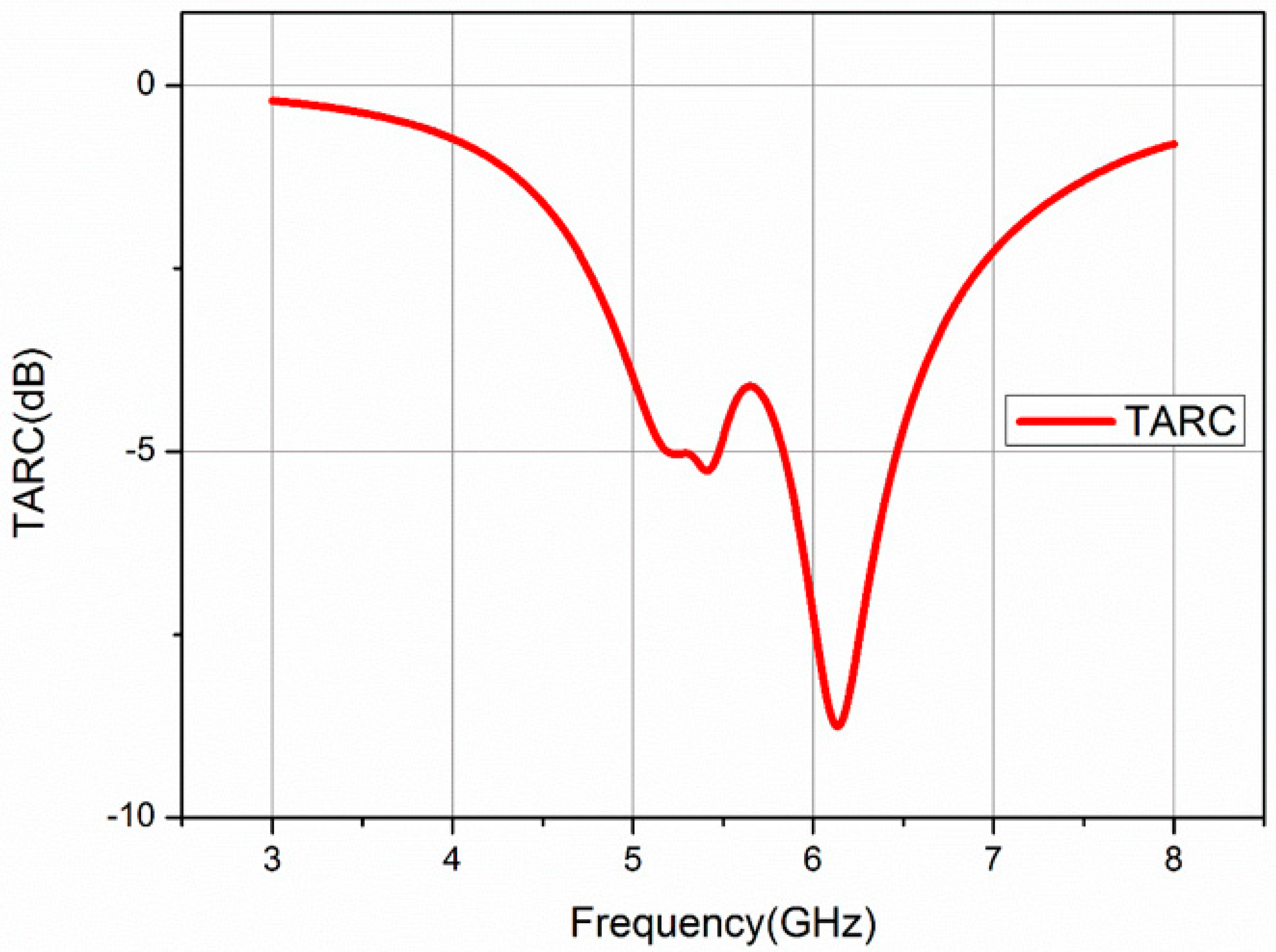
T A R C = | S 11 + S 12 e j θ | 2 + | S 21 + S 22 e j θ | 2 2
where θ is a variable and it has a range from 0 to 2 π .
The TARC of the given antenna is shown in Figure 12. The value TARC is −5.1 dB at 5.3 GHz which is suitable for the given MIMO antenna.

4.3. Efficiency

The efficiency of the antenna is a relation of the delivered power to the antenna relative to the radiated power from the antenna. Antenna with high efficiency has maximum power absorbed at the antenna’s input radiated. A low-efficiency antenna has a minimum of the power absorbed as losses within the antenna. The efficiency of the antenna can be expressed as follows:
ε R   = P r a d i a t e d P i n p u t
The efficiency of an antenna is a number between 0 and 1 being ratio. However, antenna efficiency is usually found in terms of a percentage; for example, an efficiency of 0.5 means 50% efficiency. The efficiency of the given MIMO antenna is shown in Figure 13 which is 98.01% at 5.3 GHz.

5. Comparison of Proposed Work with Related Works

As stated before, some other techniques are applied to high isolation between antenna resonators such as parasitic cells [6], differential feeding [8], neutralization [12], complementing split ring resonator [4], and annular slot [33]. One of the popular techniques for mutual coupling reduction is DGS, which is also used in previous works [25,26]. In this paper, a novel approach applied to four different DGS-shaped antennas to obtain high isolation, peak gain, low ECC, high directivity, and high efficiency.
The overall comparisons with previous works are presented in Table 2. It can be noticed from this table that, the simulated S21 (isolation) of the proposed model is ≥41 which is better than [4,6,8,12,25,26,29,30,33,34]. Gain, directivity, ECC, diversity gain, and efficiency of the given MIMO antenna are also improved in this work.

6. Conclusions

A MIMO antenna array with enhanced isolation is investigated. In this paper, two circular patch antennas are closely placed to each other on the RO3003 substrate with a thickness of 1.46 mm while using a differently shaped DGS slot for isolation in the ground layer. The main purpose of the differently shaped DGS is to obtain high mutual coupling reduction, which was obtained −41 dB in this paper while we used the H-shaped DGS.S11 parameter, S21 parameter, VSWR, total Gain, Directivity, Radiation Pattern, ECC, diversity gain, and TARC are discussed. The obtained results are −32 dB, −41 dB, 1.34, 8.40 dBi, 8.47 dBi, 0.0072, and 9.982 dB, respectively, for the above parameters at 5.3 GHz frequency. The projected antenna is valuable for the MIMO antenna system, where a high reduction of mutual coupling is required.
In the future works, the proposed simulated antenna in this paper will be fabricated for experimental validation in order to use in industry.

Author Contributions

Conceptualization, A.K.; data curation, M.A.A.; formal analysis, M.U.J. and M.A.A.; funding acquisition, S.G. and X.Z.; investigation, Z.S.; methodology, A.K., S.G. and X.Z.; project administration, S.G. and X.Z.; resources, S.G. and X.Z.; software, A.K.; supervision, S.G. and X.Z.; validation, M.U.J. and M.A.A.; visualization, Z.S.; writing—original draft, A.K.; writing—review & editing, Z.S., M.U.J. and M.A.A. All authors have read and agreed to the published version of the manuscript.

Funding

It's supported by the Science and Technology Project of State Grid Corporation of China under Grant No. SGSDDK00KJJS1900405.

Conflicts of Interest

The authors declare no conflicts of interest.

References

  1. Andrews, J.G.; Buzzi, S.; Choi, W.; Hanly, S.V.; Lozano, A.; Soong, A.C.; Zhang, J.C. What will 5G be? IEEE J. Sel. Areas Commun. 2014, 32, 1065–1082. [Google Scholar] [CrossRef]
  2. Foschini, G.J.; Gans, M.J. On limits of wireless communications in a fading environment when using multiple antennas. Wirel. Pers. Commun. 1998, 6, 311–335. [Google Scholar] [CrossRef]
  3. Yang, F.; Rahmat-Samii, Y. Microstrip antennas integrated with electromagnetic band-gap (EBG) structures: A low mutual coupling design for array applications. IEEE Trans. Antennas Propag. 2003, 51, 2936–2946. [Google Scholar] [CrossRef] [Green Version]
  4. Ramachandran, A.; Pushpakaran, S.V.; Pezholil, M.; Kesavath, V. A four-port MIMO antenna using concentric square-ring patches loaded with CSRR for high isolation. IEEE Antennas Wirel. Propag. Lett. 2015, 15, 1196–1199. [Google Scholar] [CrossRef]
  5. Arora, A.; Kumar, N. To reduce mutual coupling in microstrip patch antenna arrays elements using electromagnetic band gap structures for X-band. In Proceedings of the 2017 International Conference on Nextgen Electronic Technologies: Silicon to Software (ICNETS2), Tamilnadu, India, 23–25 March 2017; pp. 228–230. [Google Scholar]
  6. Kawakami, Y.; Kuse, R.; Hori, T.; Fujimoto, M. Decoupling of dipole antenna array on patch type metasurface with parasitic cells. In Proceedings of the 2017 11th European Conference on Antennas and Propagation (EUCAP), Paris, France, 19–24 March 2017; pp. 2603–2606. [Google Scholar]
  7. Yu, Y.; Yi, L.; Liu, X.; Gu, Z.; Li, J. Mutual coupling reduction of dual-frequency patch antennas using a simple microstrip H-Section. In Proceedings of the 2015 IEEE International Symposium on Antennas and Propagation & USNC/URSI National Radio Science Meeting, Vancouver, BC, Canada, 19–25 January 2015; pp. 388–389. [Google Scholar]
  8. Zhao, L.; Piao, D. Mutual Coupling Reduction of Microstrip MIMO Antenna Array by Differential Feeding. In Proceedings of the 2018 Cross Strait Quad-Regional Radio Science and Wireless Technology Conference (CSQRWC), Xuzhou, China, 21–24 July 2018; pp. 1–3. [Google Scholar]
  9. Wu, C.-H.; Chiu, C.-L.; Ma, T.-G. Very compact fully lumped decoupling network for a coupled two-element array. IEEE Antennas Wirel. Propag. Lett. 2015, 15, 158–161. [Google Scholar] [CrossRef]
  10. Ban, Y.-L.; Chen, Z.-X.; Chen, Z.; Kang, K.; Li, J.L.-W. Decoupled hepta-band antenna array for WWAN/LTE smartphone applications. IEEE Antennas Wirel. Propag. Lett. 2014, 13, 999–1002. [Google Scholar]
  11. Wang, H.; Liu, L.; Zhang, Z.; Li, Y.; Feng, Z. Ultra-compact three-port MIMO antenna with high isolation and directional radiation patterns. IEEE Antennas Wirel. Propag. Lett. 2014, 13, 1545–1548. [Google Scholar] [CrossRef]
  12. Zhang, S.; Pedersen, G.F. Mutual coupling reduction for UWB MIMO antennas with a wideband neutralization line. IEEE Antennas Wirel. Propag. Lett. 2015, 15, 166–169. [Google Scholar] [CrossRef]
  13. Chiu, C.-Y.; Cheng, C.-H.; Murch, R.D.; Rowell, C.R. Reduction of mutual coupling between closely-packed antenna elements. IEEE Trans. Antennas Propag. 2007, 55, 1732–1738. [Google Scholar] [CrossRef]
  14. Lee, C.-T.; Wong, K.-L. Internal WWAN clamshell mobile phone antenna using a current trap for reduced ground plane effects. IEEE Trans. Antennas Propag. 2009, 57, 3303–3308. [Google Scholar]
  15. Dadgarpour, A.; Zarghooni, B.; Virdee, B.S.; Denidni, T.A.; Kishk, A.A. Mutual coupling reduction in dielectric resonator antennas using metasurface shield for 60-GHz MIMO systems. IEEE Antennas Wirel. Propag. Lett. 2016, 16, 477–480. [Google Scholar] [CrossRef] [Green Version]
  16. Karimian, R.; Kesavan, A.; Nedil, M.; Denidni, T.A. Low-mutual-coupling 60-GHz MIMO antenna system with frequency selective surface wall. IEEE Antennas Wirel. Propag. Lett. 2016, 16, 373–376. [Google Scholar] [CrossRef]
  17. Gao, P.; He, S.; Wei, X.; Xu, Z.; Wang, N.; Zheng, Y. Compact printed UWB diversity slot antenna with 5.5-GHz band-notched characteristics. IEEE Antennas Wirel. Propag. Lett. 2014, 13, 376–379. [Google Scholar] [CrossRef]
  18. Capobianco, A.; Khan, M.; Caruso, M.; Bevilacqua, A. 3–18 GHz compact planar antenna for short-range radar imaging. Electron. Lett. 2014, 50, 1016–1018. [Google Scholar] [CrossRef]
  19. Ghosh, T.; Ghosal, S.; Mitra, D.; Bhadra Chaudhuri, S.R. Mutual coupling reduction between closely placed microstrip patch antenna using meander line resonator. Prog. Electromagn. Res. 2016, 59, 115–122. [Google Scholar] [CrossRef] [Green Version]
  20. Zhang, S.; Lau, B.K.; Sunesson, A.; He, S. Closely-packed UWB MIMO/diversity antenna with different patterns and polarizations for USB dongle applications. IEEE Trans. Antennas Propag. 2012, 60, 4372–4380. [Google Scholar] [CrossRef] [Green Version]
  21. Suntives, A.; Abhari, R. Miniaturization and isolation improvement of a multiple-patch antenna system using electromagnetic bandgap structures. Microw. Opt. Technol. Lett. 2013, 55, 1609–1612. [Google Scholar] [CrossRef]
  22. Zhu, F.-G.; Xu, J.-D.; Xu, Q. Reduction of mutual coupling between closely-packed antenna elements using defected ground structure. Electron. Lett. 2009, 45, 601–602. [Google Scholar] [CrossRef]
  23. Adamiuk, G.; Beer, S.; Wiesbeck, W.; Zwick, T. Dual-orthogonal polarized antenna for UWB-IR technology. IEEE Antennas Wirel. Propag. Lett. 2009, 8, 981–984. [Google Scholar] [CrossRef] [Green Version]
  24. Wang, L.; Wang, G.; Zhao, Q. Suppressing mutual coupling of MIMO antennas with parasitic fragment-type elements. In Proceedings of the 2016 46th European Microwave Conference (EuMC), London, UK, 4–6 October 2016; pp. 1303–1306. [Google Scholar]
  25. Kumar, A.; Devane, S. DGS based mutual coupling reduction between microstrip patch antenna arrays for WIMAX applications. In Proceedings of the 2016 2nd International Conference on Next Generation Computing Technologies (NGCT), Dehradun, India, 14–16 October 2016; pp. 78–83. [Google Scholar]
  26. Hammoodi, A.I.; Raad, H.; Milanova, M. Mutual Coupling Reduction between Two Circular Patches Using H-Shape DGS. In Proceedings of the 2018 IEEE International Symposium on Antennas and Propagation & USNC/URSI National Radio Science Meeting, Boston, MA, USA, 8–13 July 2018; pp. 1371–1372. [Google Scholar]
  27. Satapathy, S.; Mohanta, H.C. Contrastive Parametric Analysis of Rectangular and Circular Microstrip Patch Antenna. Int. J. Res. Innovation Appl. Sci. 2017, 2, 19–22. [Google Scholar]
  28. Blanch, S.; Romeu, J.; Corbella, I. Exact representation of antenna system diversity performance from input parameter description. Electron. Lett. 2003, 39, 705–707. [Google Scholar] [CrossRef] [Green Version]
  29. Mak, A.C.; Rowell, C.R.; Murch, R.D. Isolation enhancement between two closely packed antennas. IEEE Trans. Antennas Propag. 2008, 56, 3411–3419. [Google Scholar] [CrossRef]
  30. Cao, Y.; Cheung, S.W.; Yuk, T.I. Frequency-reconfigurable multiple-input–multiple-output monopole antenna with wide-continuous tuning range. IET Microw. Antennas Propag. 2016, 10, 1322–1331. [Google Scholar] [CrossRef] [Green Version]
  31. Bisht, S.; Saini, S.; Prakash, V.; Nautiyal, B. Study the various feeding techniques of microstrip antenna using design and simulation using CST microwave studio. Int. J. Emerg. Technol. Adv. Eng. 2014, 4, 318–324. [Google Scholar]
  32. Sharawi, M.S. Printed MIMO Antenna Engineering; Artech House: Norwood, MA, USA, 2014. [Google Scholar]
  33. Hussain, R.; Khan, M.U.; Sharawi, M.S. An integrated dual MIMO antenna system with dual-function GND-plane frequency-agile antenna. IEEE Antennas Wirel. Propag. Lett. 2017, 17, 142–145. [Google Scholar] [CrossRef]
  34. Qu, L.; Zhang, R.; Kim, H. Decoupling between ground radiation antennas with ground-coupled loop-type isolator for WLAN applications. IET Microw. Antennas Propag. 2016, 10, 546–552. [Google Scholar] [CrossRef]
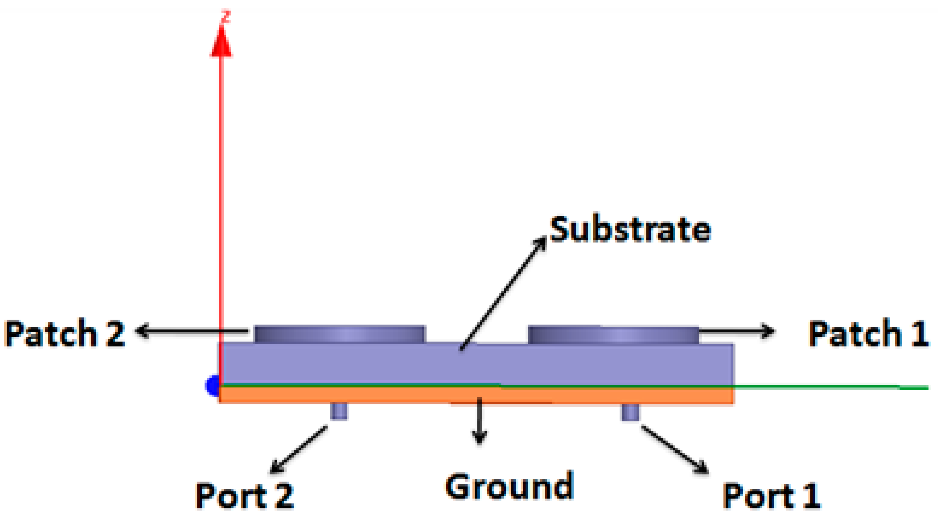
Figure 1. The proposed MIMO antenna.
Electronics 09 01217 g001
Figure 2. (a,b) A front outlook of the designed antenna.
Electronics 09 01217 g002aElectronics 09 01217 g002b
Figure 3. (ad) The geometry of the given MIMO antenna with modification in the ground plane.
Electronics 09 01217 g003
Figure 4. (a,b) Simulated S-Parameters of Antenna-1, Antenna-2, Antenna-3, and Antenna-4.
Electronics 09 01217 g004
Figure 5. Presents voltage standing wave ratio of the proposed Antenna-1, Antenna-2, Antenna-3, and Antenna-4.
Electronics 09 01217 g005
Figure 6. Shows the total gain of the proposed Antenna-1 Antenna-2, Antenna-3, and Antenna-4.
Electronics 09 01217 g006
Figure 7. Directivity of Antenna-1, Antenna-2, Antenna-3, and Antenna-4.
Electronics 09 01217 g007
Figure 8. (ad) Simulated radiation patterns at 5.3 GHz.
Electronics 09 01217 g008
Figure 9. Surface current distribution for (a) Antenna-1, (b) Antenna-2, (c) Antenna-3, and (d) Antenna-4.
Electronics 09 01217 g009
Figure 10. Envelope correlation coefficient.
Electronics 09 01217 g010
Figure 11. Simulated diversity gain.
Electronics 09 01217 g011
Figure 12. Simulated total active reflective coefficient.
Electronics 09 01217 g012
Figure 13. Simulated radiation efficiency.
Electronics 09 01217 g013
Table 1. Dimensions of the proposed MIMO antenna.
ParametersValue (mm)ParametersValue (mm)
Substrate length (L)60Patch-2 radius (R2)9
Substrate width (W)50Pin-2 radius0.6
Height (H)1.46Pin-2 height3
Permittivity   ( ε r )3Probe-2 radius0.6
Patch-1 radius (R1)9Probe-2 height1.46
Ground length60Coaxial-2 radius1
Ground width50Coaxial-2 height3
Pin-1 radius0.6Ground cutoff-1 length (Ls)23
Pin-1 height3Ground cutoff-2 length (Ws)16.5
Probe-1 radius0.6Ground cutoff-3 length (Ws)16.5
Probe-1 height1.46Ground cutoff width0.2
Coaxial-1 radius1Port-1 radius1
Coaxial-1 height3Port-2 radius1
Ground cut off-1 radius1Ground cut off-2 radius1
Table 2. Performance comparisons with the related works.
Ref.Isolation TechniqueS21 (dB)Gain (dB)ECCEfficiency (%)
[4]CSRR−223.40.484.6
[6]Parasitic cells−13NANANA
[8]Differential feeding−178NANA
[12]Neutralization Line−2250.1NA
[25]DGS 1-antenna−17NANANA
[26]DGS2-antennas−185.5NANA
[29]Rectangular slot−302NA65
[30]U-shape slot−201.60.5NA
[33]Annular slot−222.30.01583
[34]Loop type−142.050.362.5
ProposedDGS 4-antennas−418.400.007298.01