Article

Area-Efficient Differential Fault Tolerance Encoding for Finite State Machines

Department of Electronics Engineering, Chungnam National University, Daejeon 34134, Korea
*
Author to whom correspondence should be addressed.
Electronics 2020, 9(7), 1110; https://doi.org/10.3390/electronics9071110
Submission received: 14 June 2020 / Revised: 4 July 2020 / Accepted: 5 July 2020 / Published: 8 July 2020
(This article belongs to the Section Circuit and Signal Processing)

Abstract

:
A differential fault tolerance encoding is presented for finite state machines (FSMs) to improve their area efficiency. As the manufacturing technology for semiconductors continues to scale down, the probability of the occurrence of unexpected faults in integrated circuits has been increasing. Because an FSM controls an entire digital circuit, the faults in FSMs should be carefully addressed. Whereas the previous encoding applies a fault tolerance scheme to all the states in an FSM, the proposed encoding applies a fault tolerance scheme to only specific states depending on their importance. Compared with the previous complete fault tolerance encoding, the proposed encoding provides a comparable failure probability with a small hardware by applying the fault tolerance scheme differently to each state. The proposed method improves the area efficiency by 36.1%, 43.8%, 49.2%, and 74.6% compared with that by the non-fault tolerance, previous hardware redundancy, information redundancy, and time redundancy methods, respectively. Consequently, the proposed method can provide a flexible solution by applying the fault tolerance differently depending on the importance of the states.

1. Introduction

The finite state machine (FSM) is a popular technique used to model the complex operations of a general device. With the inputs provided, a device can be systematically controlled following the transition from the current state to the next state based on an FSM. Two types of FSMs are widely used, namely Mealy [1] and Moore [2] machines. Moore [2] machines determine the outputs according to only the current state, whereas Mealy [1] machines determine the output according to both the current state and current inputs. Due to the intuitive description of Mealy [1] and Moore [2] machines, FSMs are widely adopted in various operational models [3,4,5]. In particular, modern digital circuits generally employ FSMs to build control paths that control the data path efficiently [6,7]. Furthermore, FSMs should be carefully dealt with because even a minute variation in them could completely alter the overall operation of the digital circuits [6,7].
As the manufacturing technology for semiconductors continues to scale down, designing high-performance hardware with a smaller size, high throughput, and low power consumption has become an easy task for circuit designers. However, the probability of the occurrence of unexpected faults inevitably increases in integrated circuits [8,9]. Because it is impossible to eliminate unexpected faults completely, the faults should be carefully considered, beginning with the design stage to the manufacturing stage [10]. In general, faults are categorized into event upset and event transient, depending on the fault location. Event upset represents the type of fault that flips the stored bit in storage due to an energetic particle hit, and event transient represents the type of fault that generates a temporary pulse in the output of a logic gate by colliding an energetic particle with a logic gate [10,11]. Temporary event upset and event transient, known respectively as single event upset (SEU) [12,13] and single event transient (SET) [14,15], constitute the majority of the various types of faults in modern integrated chips [8,16].
To mitigate this problem, we propose a novel area-efficient and fault-tolerant encoding for FSMs. First, the proposed method divides the states into critical and non-critical states depending on the importance of the states. Then, different fault tolerances are imparted into the two sets of states. Strong fault tolerances are supported on critical states, and weak fault tolerances are supported on non-critical states. According to experimental results, the proposed method can provide a flexible area-efficient solution by applying the fault tolerance differently depending on the importance of the states. The remainder of this paper is organized as follows. Section 2 describes the background of the FSMs and the previous fault tolerant techniques. Section 3 explains the proposed discriminative encoding that provides different fault tolerances on states depending on the importance of the states. Section 4 discusses the experimental results using ISCAS’91 benchmarks, followed by concluding remarks in Section 5.

2. Background

2.1. Finite State Machine

Generally, the first step in designing an FSM is to define the operation of the digital circuits as a finite number of states. Once the states are defined, each state describes the transition and the output according to the input. To design an FSM concisely, Mealy and Moore machines are widely used; the difference between these machines lies in the factors that affect the output. Mealy machines determine the output depending on both the current state and current inputs, and Moore machines determine the output depending on only the current state. Generally, Mealy machines demand fewer states with complex output logics, whereas Moore machines demand a large number of states with simple output logics. Because this research focuses on fault-tolerant encoding rather than the FSM structure, for a concise elucidation, we provide explanations based on a Mealy machine with complex output logics. It is noticeable that the proposed method can be applied to Moore machines without the loss of generality.
We adopt a dk17 FSM as an example, which is obtained from the widely used ISCAS’91 FSM benchmark, to explain the conventional and fault-tolerant FSM encoding throughout the manuscript. Figure 1 and Table 1 show the state transition graph and state transition table, respectively, for a dk17 FSM obtained from the ISCAS’91 FSM benchmark; the graph and the table provide intuitive information about the FSM. The FSM consists of eight states, represented as Si ( 0 i 7 ), with a two-bit input I and three-bit output O (Figure 1 and Table 1). The next state Sj and output O are determined based on current state Si and input I. For example, when current S0 receives input I = 01, the next state becomes S3 and the output is computed as O = 010. Because Si is a symbol, it is necessary to represent state Si as a binary number to implement hardware, which is termed as state encoding. In general, binary encoding is widely used to assign the binary number of i to the ith (Table 1). Because the encoding affects the overall performance of the FSM, it should be designed carefully [16].
Figure 2 depicts a typical block diagram of the FSMs, which consists of a state register, next state logic, and output logic [17,18]. The n-bit state register stores the current state when the binary state encoding is applied, where n denotes the log of the total number of states [19]. The next state logic and output logic are responsible for calculating the next state and output, given the current state and input [17]. It is noticeable that the two logics are implemented with all combinational logics. Due to the simple structure of the FSM (Figure 2), FSMs are widely used to design the control paths in modern digital systems.

2.2. Fault-Tolerant Techniques

Because of the nanoscales used in the manufacturing of semiconductors, the increase in the number of malicious faults, such as event upsets, is inevitable in the existing integrated chips [8,9]. To mitigate this problem, these faults should be carefully dealt with, beginning from the design stage to the manufacturing stage. As mentioned earlier, the redundancy technique is a very popular method that can be implemented right from the design stage to improve the fault tolerance. The redundancy is mainly divided into three types: (1) hardware [20,21,22], (2) time [23], and (3) information redundancy [24].
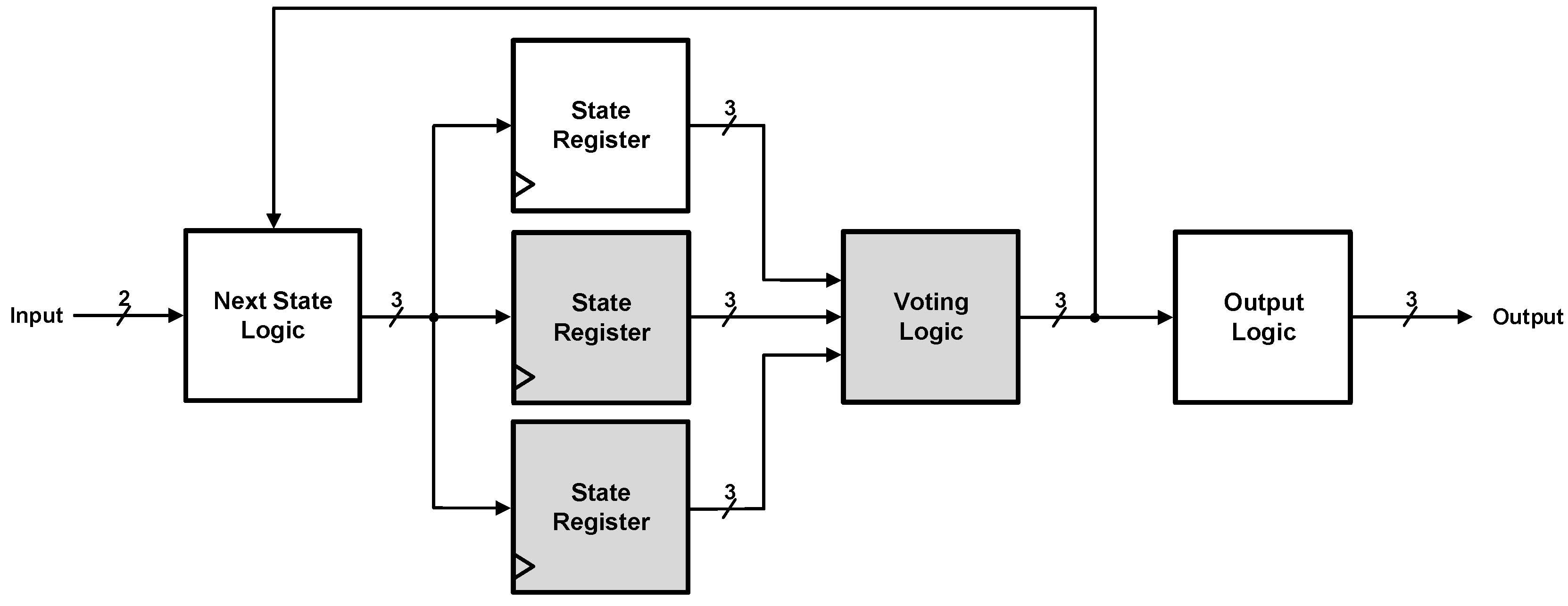
Hardware redundancy [20,21,22] duplicates the original design by as many as the redundancy number R. Based on the majority votes, the final output is determined from among the R outputs of different hardware. For the case of R = 3, Figure 3 shows the example of a block diagram of a dk17 FSM with hardware redundancy [20,21,22], where the gray color indicates the additional hardware resources compared to the typical FSM structure. Although hardware redundancy [20,21,22] is simple to design, as shown in Figure 3, it demands the same amount of additional hardware as the redundancy number R. The hardware complexity increases substantially when a large redundancy number R is applied. Next, we discuss time redundancy. Time redundancy [23] provides fault tolerance by performing the same operation repetitively with the same hardware for the number of times corresponding to redundancy number R. Figure 4 shows the example of a block diagram of a dk17 FSM with time redundancy [20,21,22] with an additional check register and exclusive-or gate. Compared with that for hardware redundancy [20,21,22] in Figure 3, the amount of additional hardware required in time redundancy [23] is negligible, as shown in Figure 4; however, time redundancy [23] deteriorates the latency due to the large value of R resulting from additional iterations. Finally, information redundancy [24] uses additional redundant bits to represent binary numbers. In FSMs, information redundancy [24] can provide a solution that is intermediate between that of the hardware and the time redundancy techniques. For instance, the Hamming-h technique for FSMs was introduced, where Hamming distance h indicates the number of bit differences between binary vectors [24]. As the Hamming distance increases, information redundancy can provide strong fault tolerance. Table 2 shows an example of H-2 and H-3 encoding for a dk17 FSM, where H-h represents encoding with Hamming distance h. As shown in Table 2, the vectors in H-2 differ by 2 bits at most, enabling it to provide single bit fault detection. Additionally, the vectors in H-3 differ by 3 bits at most, enabling it to provide single bit fault correction. Note that binary encoding can be interpreted as H-1; thus, it can provide no fault tolerance at all. As shown in Figure 5, the previous H-h [24] in information redundancy can provide desirable fault tolerance with a small increase in the number of hardware and latency, but it must be improved further in terms of hardware efficiency.

3. Proposed Method

The main principle behind the proposed method is to provide differential fault tolerance for the states according to the importance of the states. Whereas the previous H-h [24] encodes the states of an FSM with the same Hamming distance h irrespective of the importance of the states, the proposed method does this with different Hamming distances. More precisely, strong fault tolerance equipped with long Hamming distance is applied to the critical states, and weak fault tolerance resulting from a short Hamming distance is applied to the non-critical states. Because the hardware complexity is proportional to the Hamming distance, the proposed method can provide an area-efficient solution by providing different H-l and H-s to maintain the desirable fault tolerance. The proposed method involves three steps, namely state classification, state encoding, and FSM construction, which are discussed next.

3.1. State Classification

The first step in the proposed method is to classify the states in an FSM into critical state SC and non-critical state SNC based on their importance. In the proposed method, we define the importance of a state based on the frequency of its occurrence. When a state occurs frequently, the state determined to require strong fault tolerance is classified as the critical state. Contrarily, when the occurrence of a state is less, the state determined not to require strong fault tolerance is classified as the non-critical state. To clarify the criterion for this classification, we define the coverage C affected by strong fault tolerance, which indicates the frequency ratio of the critical states through the entire operation, i.e., C = # S C / ( # S C + # S N C ) , where #Sc and #SNC denote the numbers of clock cycles associated with the critical and non-critical states, respectively. The classification process proceeds as follows:
  • Count the frequency of each state using an ordinary FSM with random inputs;
  • List the states based on their descending order of frequency;
  • Extract a state from the top of the frequency list and include it in the critical state Sc;
  • Repeat step (3) until the accumulation of frequency exceeds the coverage C;
  • Include the remaining states in the non-critical state SNC.
Following this process, all the states are classified into critical and non-critical states by satisfying the condition that the accumulated ratio of the most frequent states exceeds the coverage C. It means that the strong fault tolerance affects more than C when applying strong fault tolerance to the critica state SC. Note that step 1 should be performed until the frequency is saturated, to achieve a reliable frequency.
Table 3 lists the state classification for a dk17 FSM. To achieve a reliable frequency, step 1 is iteratively performed 107 times with random inputs. As a result, the frequency of the original states of a dk17 FSM is sorted in descending order and accumulated. Table 3 indicates that S3 is the most frequent state with a frequency of 24.58%, whereas S6 is the least frequent state with a frequency of 0.96%. For various values of target coverage C, the critical state becomes different, as shown in Table 3. For instance, the critical set includes (S3, S2) and (S3, S2, S4) for the cases of C = 30% and C = 60%, respectively. Note that C = 0% indicates a non-fault-tolerant FSM, and C = 100% corresponds to the previous H-h FSM. Table 3 divides the states into two sets; however, the proposed method can be extended further by dividing the states into more than two sets to realize finely controlled fault tolerance.

3.2. State Encoding

After the classification of the states, the next step is to assign a strong fault tolerance to the critical state and a weak fault tolerance to the non-critical state. Generally, the Hamming distance is used to represent the capability of fault tolerance, because h = ( 2 t + 1 ) encoding guarantees t fault correction at most. For instance, H-3 and H-5 can correct one and two faults at most, respectively. Therefore, the register-transfer level design selects a suitable Hamming distance for each critical and non-critical set individually. Table 4 illustrates the state encoding manner depending on the Hamming distance in the case of a dk17 FSM; here, we assumed that coverage C = 60% with SC = {S3, S2, S4}. In Table 4, the pairs of (H-hs, H-hw) represent that a strong Hamming encoding of H-hs is applied to the critical state and a weak hamming encoding of H-hw is applied to the non-critical state, where h s h w . As for the coverage C = 60%, the critical set containing S3, S2, and S4 maintains the Hamming distance hs, and the non-critical set containing S0, S1, S5, S6, and S7 maintains the Hamming distance hw. Because a strong fault tolerance demands a long Hamming distance, the number of bits required to encode the states increases with the increasing Hamming distance. Furthermore, Table 5 shows the state encoding manner depending on the coverage C of a dk17 FSM; here, we assume that the pair (H-3, H-1) is applied. The number of states in the critical set increases to 2, 3, and 5, as the coverage C extends from 30% to 90%. Because the critical state demands a larger number of bits than the non-critical state, the total number of bits required to encode the states increases as the number of critical states increases. It is thus apparent that a longer bit is inevitably required for realizing stronger fault tolerance and wider coverage.

3.3. FSM Construction

Finally, a new state transition table should be completed to construct an FSM for the proposed differential encoding. We additionally define a redundant state SR, which possesses the error correction capability. The redundant state SR, neighboring the critical state in terms of encoding, is assigned to the same operation as the critical state. When a minor fault occurs in the critical state SC, there is a high probability of moving the redundant state SR, resulting in fault correction by performing a similar operation to the original one. As an example, Table 6 shows the state transition table for the proposed differential (H-3, H-1) encoding with coverage C = 60%. The critical states S2, S3, and S4 are protected using a redundant state SR that generates an identical next state and output. For instance, when a single fault occurs on S2 at any bit position, an identical next function S0 and output O = 001 in I = 00 can be obtained using the redundant state SR. Given the state transition table, FSM can be implemented based on a typical FSM, as shown in Figure 6. The proposed method encodes the states differentially by assigning more bits to the critical states and fewer bits to the non-critical states. Because the bit length obtained from state encoding determines the hardware complexity of the overall FSM, the proposed method can provide an area-efficient fault-tolerant encoding for FSMs. Note that the additional logic in the proposed method is smaller than that in the information redundancy method due to the differential encoding. Furthermore, the proposed method can be simply extended to more than two types of states corresponding to the importance of the states; however, this section focused only on a case with two types of states.

4. Experimental Results

For a fair comparison, we implement four FSMs from ISCAS’91 FSM benchmarks using a 180 nm CMOS process. Because the proposed method provides a flexible solution, a non-fault tolerance can be interpreted as corresponding to the proposed method with C = 0%, and the previous H-h encoding [24] to the proposed method with C = 100%. First, the area complexity is compared in terms of equivalent gate counts, and the failure rate is analyzed with single, double, and triple fault cases. Finally, the area efficiency calculated from the two comparisons is described to verify the advantages of the proposed method.
Among the various FSMs available in the ISCAS’91 FSM benchmark, we adopt four FSMs, namely dk17, dk512, bbara, and beecount, since they are synthesizable and provide FSM states from 7 to 15. After designing various FSMs with different coverages and fault tolerances, they are synthesized via a 180 nm CMOS process at the working frequency of 200 MHz. Figure 7 shows the equivalent gate counts according to coverage C and Hamming distance h. Figure 7 shows that the hardware complexity increases as the coverage increases and the Hamming distance increases due to the increase in the number of state bits. Note that the previous non-fault tolerance represented by C = 0% involves the least hardware complexity, and the previous Hamming represented by C = 100% involves the highest hardware complexity, for all cases.
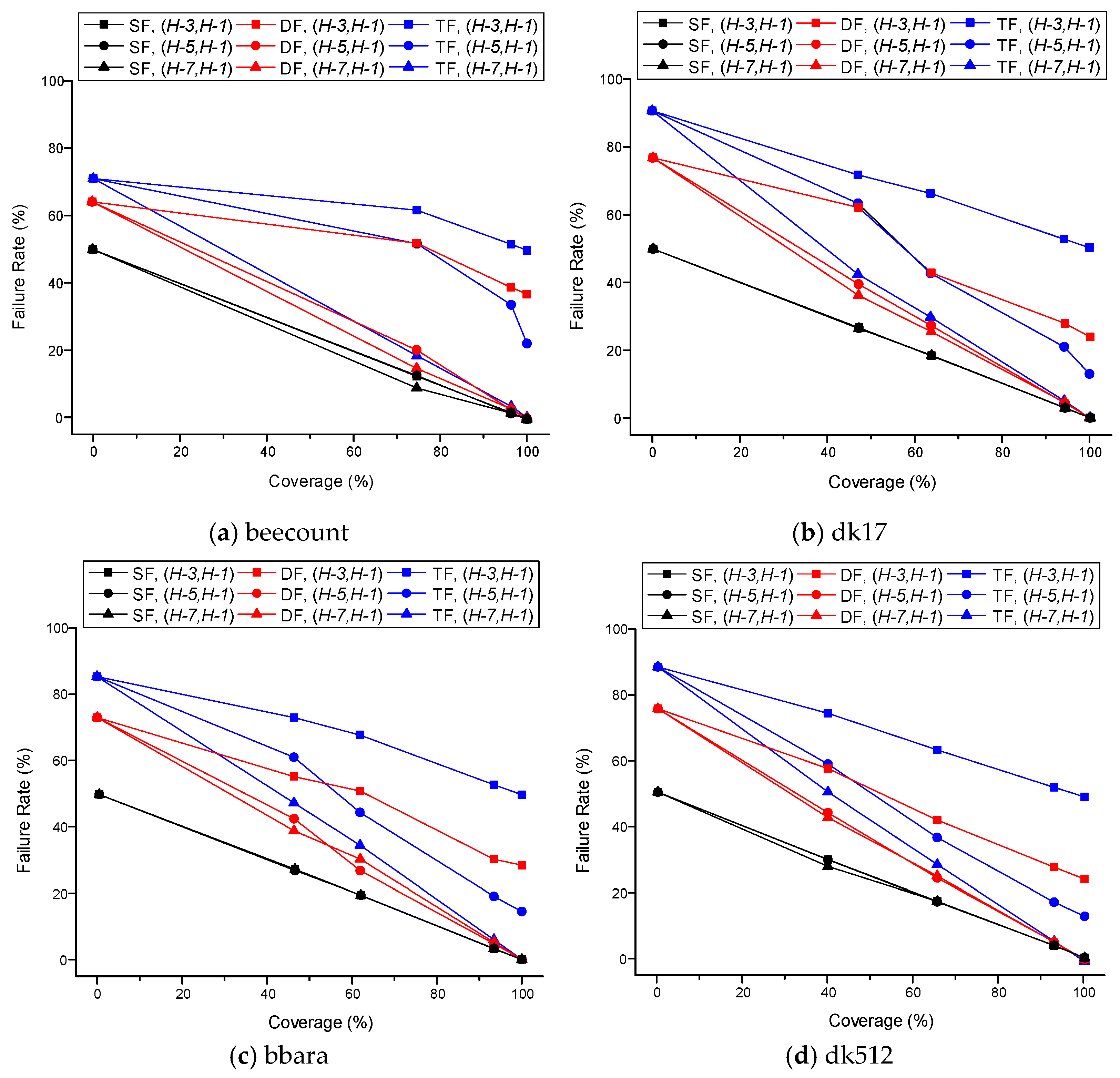
Moreover, the fault rate is analyzed for the proposed method with different coverages and Hamming distances. To perform a practical simulation [25], the error model is designed based on real fault patterns. The stuck-at-zero and stuck-at-one models are used, which represent the situation in which an energetic particle causes the fixed state of the storage temporally [26]. For the number of faults, [8] indicates that SEU is the most frequent fault, and single event multiple upset (SEMU) with up to three bits is dominant in modern integrated circuits [27]. To compute the fault rate of an FSM, it is operated for 1024 clock cycles and random faults using either stuck-at-zero or stuck-at-one models are inserted for one clock cycle [25,28]. Figure 8 shows the failure rate of the proposed method, in which a failure in FSM counts when either the output or the current state of normal operation without faults is different from that of a faulty operation. To account for the cases of both SEU and SEMU, various failure rates are computed under single, double, and triple fault injections [27], as depicted. Figure 8 shows that the failure ratio improves due the increase in the coverage and the Hamming distance caused by providing strong fault tolerance on more states. The previous non-fault tolerance represented by C = 0% provides the worst fault tolerance and the previous Hamming encoding represented by C = 100% provides the best fault tolerance, in all cases.
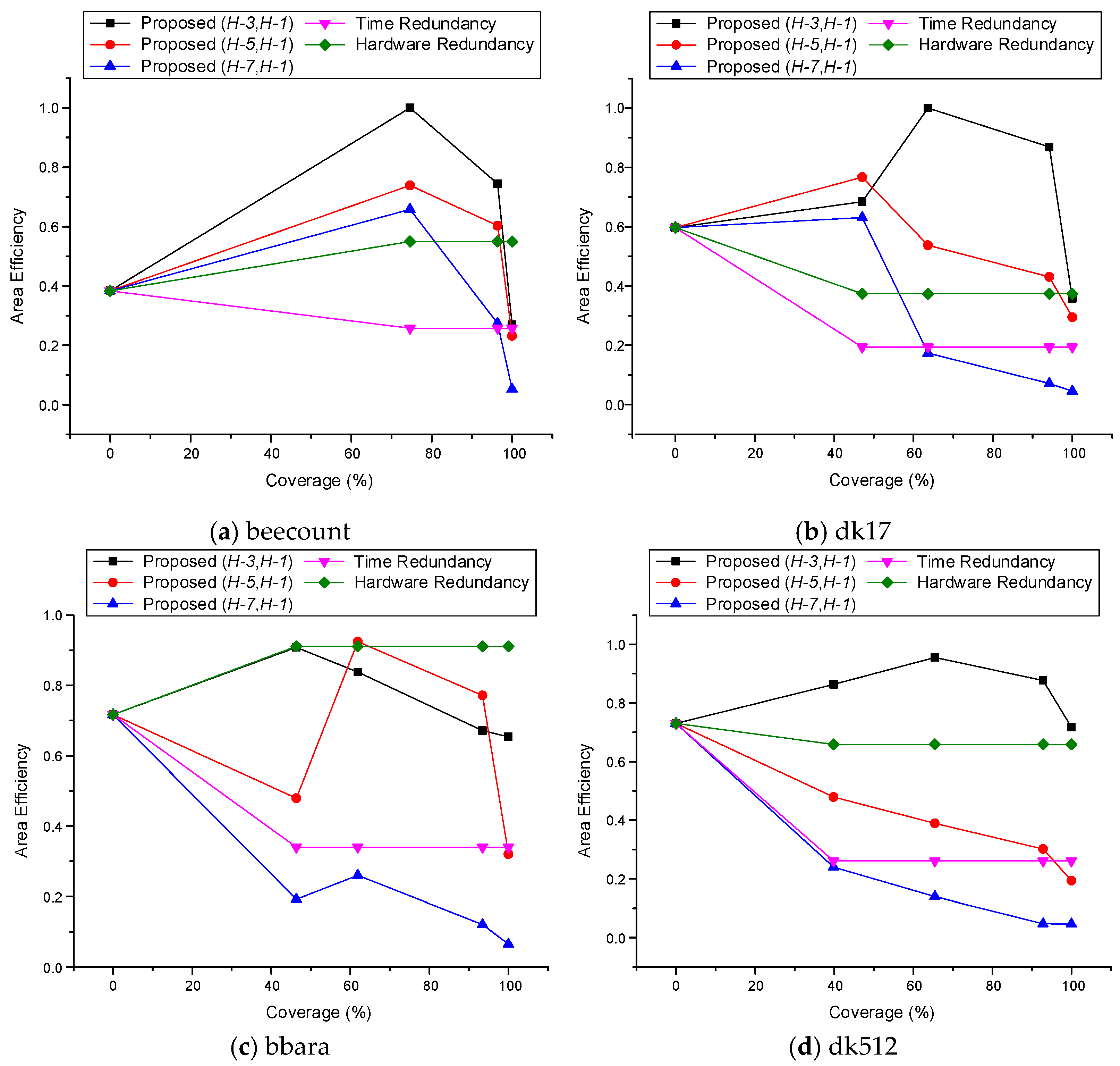
Finally, we compare the area efficiency of the proposed method. In this comparison, area efficiency is measured by a normalized ( 100 failure   rate ) / ( area × latency ) . The non-fault tolerance encoding interpreted as C = 0% of the proposed method exhibits the smallest area requirement with the worst failure rate. Contrarily, the previous Hamming encoding interpreted as C = 100% of the proposed method exhibits the largest area requirement with the best failure rate. Therefore, it is clear that unlike the two extreme cases of the previous method, the proposed method can provide an intermediate solution that requires a feasible area with a reliable failure rate by improving the area efficiency. Figure 9 shows the area efficiency according to the coverage C and Hamming distance h. The proposed method can provide a better solution than the previous encoding at all times. On average, the proposed method improves the area efficiency by 36.1% and 49.2% compared with that by non-fault tolerance (C = 0%) and Hamming encoding (C = 100%), respectively. Furthermore, the proposed method improves the area efficiency by 43.8% and 74.6% compared with that by previous hardware redundancy and time redundancy, respectively. As a result, the proposed method can provide the most efficient method compared to previous hardware, time, and information redundancy methods. Since the proposed method can be applied to any FSMs, it is allowed to apply the proposed method for any modern circuits equipped with an FSM.

5. Conclusions

An area-efficient encoding method was proposed for FSMs to encode the states differently depending on the importance of the states. Unlike the previous non-fault tolerance or complete fault tolerance encoding with a constant Hamming distance, the proposed method classifies the states into critical and non-critical states. After this classification, the proposed method provides a strong fault tolerance to the critical states and a weak fault tolerance to the non-critical states. The fault tolerance results from a long Hamming distance, which increases the hardware complexity. According to the experimental results using the ISCAS’91 FSM benchmarks, the proposed method provides a flexible solution to assign different fault tolerances rather than a fixed fault tolerance. The proposed method improves the area efficiency by 36.1%, 43.8%, 49.2%, and 74.6% compared with that by the non-fault tolerance, previous hardware redundancy, information redundancy, and time redundancy methods, respectively. Furthermore, the proposed method can be extended by classifying the states into more than two sets to realize finely controlled fault tolerance to further improve the area efficiency. For future research, we aim to study a stronger fault-tolerant method resistant to multiple upsets. The proposed method has a limitation in that it supports only single event upset and single event transient. Thus, further research will be conducted on supporting multiple event upset and transient to enhance fault tolerance.

Author Contributions

Conceptualization, H.Y.; methodology, J.P.; software, J.P.; validation, J.P. and H.Y.; formal analysis, H.Y.; investigation, J.P.; resources, J.P.; data curation, J.P.; writing—original draft preparation, J.P.; writing—review and editing, H.Y.; visualization, J.P.; supervision, H.Y.; project administration, H.Y.; funding acquisition, H.Y. All authors have read and agreed to the published version of the manuscript.

Funding

This work was supported by the Brain Korea 21 Plus and by the National Research Foundation of Korea (NRF) grant funded by the Korea government (MSIT) (NRF-2019M3F3A1A01074449).

Conflicts of Interest

The authors declare no conflict of interest.

References

  1. Mealy, G.H. A method for synthesizing sequential circuits. Bell Syst. Tech. J. 1955, 34, 1045–1079. [Google Scholar] [CrossRef]
  2. Moore, E.F. Gedanken-experiments on sequential machines. Autom. Stud. 1956, 34, 129–153. [Google Scholar]
  3. Xu, J.; Dong, F.; Tian, P.; Tang, F.; Yang, Q. Design and implementation of HL-2A host centralized control system FSM model based on EPICS. IEEE Trans. Plasma Sci. 2018, 46, 1234–1238. [Google Scholar] [CrossRef]
  4. Sharma, C.; Chauhan, D.K. High performance low power AHB DMA controller with FSM decomposition technique. In Proceedings of the 2017 IEEE International Conference on Power, Control, Signals and Instrumentation Engineering (ICPCSI), Chennai, India, 21–22 September 2017. [Google Scholar]
  5. Chu, S.I.; Hsieh, C.E.; Huang, Y.J. Design of FSM-based function with reduced number of states in integral stochastic computing. IEEE Trans. Very Large Scale Integr. (Vlsi) Syst. 2019, 27, 1475–1479. [Google Scholar] [CrossRef]
  6. Rathor, V.S.; Garg, B.; Sharma, G.K. An energy-efficient trusted fsm design technique to thwart fault injection and trojan attacks. In Proceedings of the 2018 31st International Conference on VLSI Design and 2018 17th International Conference on Embedded Systems (VLSID), Maharashtra, India, 6–10 January 2018. [Google Scholar]
  7. Nahiyan, A.; Farahmandi, F.; Mishra, P.; Forte, D.; Tehranipoor, M. Security-aware FSM design flow for identifying and mitigating vulnerabilities to fault attacks. IEEE Trans. Comput. Aided Des. Integr. Circuits Syst. 2018, 38, 1003–1016. [Google Scholar] [CrossRef]
  8. Hashimoto, M.; Liao, W. Soft Error and Its Countermeasures in Terrestrial Environment. In Proceedings of the 2020 25th Asia and South Pacific Design Automation Conference (ASP-DAC), Beijing, China, 13–16 January 2020. [Google Scholar]
  9. Raji, M.; Sabet, M.A.; Ghavami, B. Soft error reliability improvement of digital circuits by exploiting a fast gate sizing scheme. IEEE Access 2019, 7, 66485–66495. [Google Scholar] [CrossRef]
  10. Gaillard, R. Single event effects: Mechanisms and classification. In Soft Errors in Modern Electronic Systems; Springer: Berlin/Heidelberg, Germany, 2011; pp. 27–54. [Google Scholar]
  11. Lei, L.; Yinghui, L.; Hongwei, Z.; Xuesong, Z.; Qingkui, Y.; Min, T. Single Event Effect Detection and Simulation Analysis for an ASIC. In Proceedings of the 2019 2nd International Conference on Information Systems and Computer Aided Education (ICISCAE), Dalian, China, 6–8 July 2019. [Google Scholar]
  12. Hiemstra, D.M.; Kirischian, V.; Brelski, J. Single event upset characterization of the Kintex UltraScale field programmable gate array using proton irradiation. In Proceedings of the 2016 IEEE Radiation Effects Data Workshop (REDW), Portland, OR, USA, 11–15 July 2016. [Google Scholar]
  13. Ciani, L.; Catelani, M. A fault tolerant architecture to avoid the effects of Single Event Upset (SEU) in avionics applications. Measurement 2014, 54, 256–263. [Google Scholar] [CrossRef]
  14. Evans, A.; Glorieux, M.; Alexandrescu, D.; Polo, C.B.; Ferlet-Cavrois, V. Single event multiple transient (SEMT) measurements in 65 nm bulk technology. In Proceedings of the 2016 16th European Conference on Radiation and Its Effects on Components and Systems (RADECS), Bremen, Germany, 19–23 September 2016. [Google Scholar]
  15. Hao, P.; Chen, S.; Wu, Z.; Chi, Y. On-chip relative single-event transient/single-event upset susceptibility test circuit for integrated circuits working in real time. IEEE Trans. Nucl. Sci. 2017, 65, 376–381. [Google Scholar] [CrossRef]
  16. Nahiyan, A.; Xiao, K.; Yang, K.; Jin, Y.; Forte, D.; Tehranipoor, M. AVFSM: A framework for identifying and mitigating vulnerabilities in FSMs. In Proceedings of the the 53rd Annual Design Automation Conference, Austin, TX, USA, 5–9 June 2016. [Google Scholar]
  17. Li, S.; Choi, K. A high performance low power implementation scheme for FSM. In Proceedings of the 2014 International SoC Design Conference (ISOCC), Jeju, Korea, 3–6 November 2014. [Google Scholar]
  18. El-Maleh, A.H.; Al-Qahtani, A.S. A finite state machine based fault tolerance technique for sequential circuits. Microelectron. Reliab. 2014, 54, 654–661. [Google Scholar] [CrossRef]
  19. Madhumithaa, S.P.; Aravind, S.; Ch, R.P. A Diagnosis Pattern Generation Procedure to Distinguish Between Stuck-at and Bridging Faults in Digital Circuits. In Proceedings of the 2019 International Conference on Intelligent Computing and Control Systems (ICCS), Madurai, India, 15–17 May 2019. [Google Scholar]
  20. Zhang, J.; Li, Y.; Han, T.; Li, J. Radiation Hardened Design Based on TMR_5DFF for ASIC. In Proceedings of the 2019 IEEE 5th International Conference on Computer and Communications (ICCC), Chengdu, China, 6–9 December 2019. [Google Scholar]
  21. Mallavarapu, P.; Upadhyay, H.N.; Rajkumar, G.; Elamaran, V. Fault-tolerant digital filters on FPGA using hardware redundancy techniques. In Proceedings of the 2017 International conference of Electronics, Communication and Aerospace Technology (ICECA), Coimbatore, India, 20–22 April 2017. [Google Scholar]
  22. Hamilton, N.; Graham, S.; Carbino, T.; Petrosky, J.; Betances, A. Adaptive-Hybrid Redundancy with Error Injection. Electronics 2019, 8, 1266. [Google Scholar] [CrossRef] [Green Version]
  23. Alvarez, I.; Proenza, J.; Barranco, M.; Knezic, M. Towards a time redundancy mechanism for critical frames in Time-Sensitive Networking. In Proceedings of the 2017 22nd IEEE International Conference on Emerging Technologies and Factory Automation (ETFA), Limassol, Cyprus, 12–15 September 2017. [Google Scholar]
  24. Sooraj, S.; Bhakthavatchalu, R. Hamming 3 algorithm for improving the reliability of SRAM based FPGAs. In Proceedings of the 2017 International Conference on Communication and Signal Processing (ICCSP), Tamilnadu, India, 6–8 April 2017. [Google Scholar]
  25. Eslami, M.; Ghavami, B.; Raji, M.; Mahani, A. A survey on fault injection methods of digital integrated circuits. Integration 2020, 71, 154–163. [Google Scholar] [CrossRef]
  26. Choi, S.; Park, J.; Yoo, H. Area-Efficient Fault Tolerant Design for Finite State Machines. In Proceedings of the 2020 International Conference on Electronics, Information, and Communication (ICEIC), Barcelona, Spain, 19–22 January 2020. [Google Scholar]
  27. Fabero, J.C.; Mecha, H.; Franco, F.J.; Clemente, J.A.; Korkian, G.; Rey, S.; Velazco, R. Single Event Upsets under 14-MeV Neutrons in a 28-nm SRAM-based FPGA in Static Mode. IEEE Trans. Nucl. Sci. 2020. [Google Scholar] [CrossRef] [Green Version]
  28. Wu, K.; Pahlevanzadeh, H.; Liu, P.; Yu, Q. A new fault injection method for evaluation of combining SEU and SET effects on circuit reliability. In Proceedings of the 2014 IEEE International Symposium on Circuits and Systems (ISCAS), Melbourne, Australia, 1–5 June 2014. [Google Scholar]
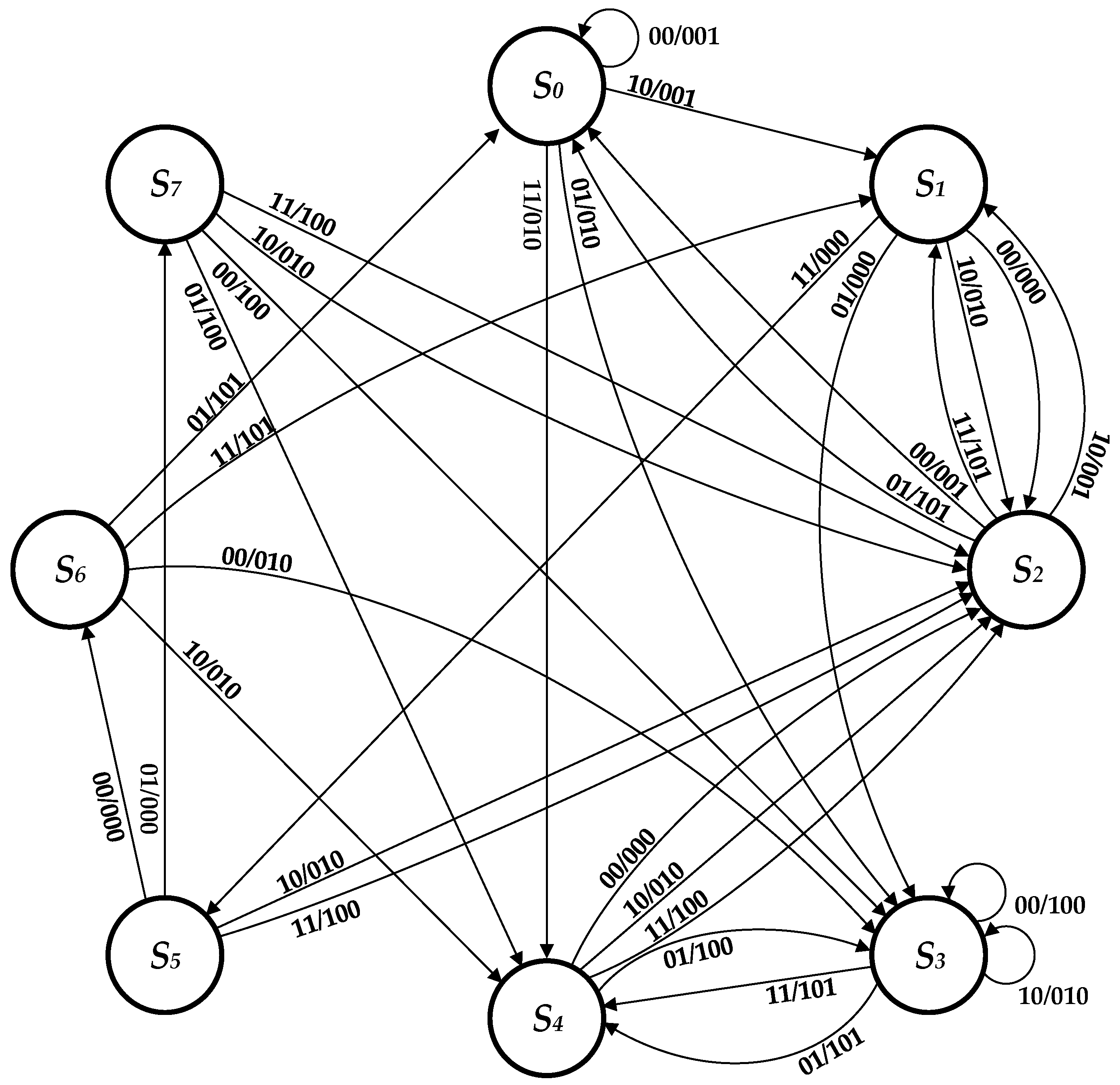
Figure 1. State transition graph for dk17 FSM (finite state machines).
Electronics 09 01110 g001
Figure 2. Block diagram of dk17 FSM structure.
Electronics 09 01110 g002
Figure 3. Block diagram of dk17 FSM structure with hardware redundancy.
Electronics 09 01110 g003
Figure 4. Block diagram of dk17 FSM structure with time redundancy.
Electronics 09 01110 g004
Figure 5. Block diagram of dk17 FSM structure with information redundancy.
Electronics 09 01110 g005
Figure 6. Block diagram of dk17 FSM structure of proposed (H-3, H-1) with C = 60%.
Electronics 09 01110 g006
Figure 7. Equivalent gate counts for fault-tolerant FSMs.
Electronics 09 01110 g007
Figure 8. Failure rates for fault-tolerant FSMs.
Electronics 09 01110 g008
Figure 9. Area efficiency for fault-tolerant FSMs.
Electronics 09 01110 g009
Table 1. State transition table encoded with binary encoding.
StateNext StateOutputs
I = 00I = 01I = 10I = 11I = 00I = 01I = 10I = 11
S0(000)S0S3S1S4001010001010
S1(001)S2S3S2S5000000010000
S2(010)S0S0S1S1001101001101
S3(011)S3S4S3S4100101010101
S4(100)S4S3S4S4000100010100
S5(101)S6S7S2S2000000010100
S6(110)S3S0S4S1010101010101
S7(111)S3S4S2S2100100010100
Table 2. Example of state assignment for Hamming distances.
StateH-1H-2H-3
S0(000)0000000000000
S1(001)0011001001011
S2(010)0101010010110
S3(011)0110011011101
S4(100)1001100100111
S5(101)1010101101100
S6(110)1100110110001
S7(111)1111111111010
Table 3. Example of state classification for different coverage.
StateFrequencyAccumulationC = 0%C = 30%C = 60%C = 90%C = 100%
S324.58%24.58%SNCSCSCSCSC
S222.48%47.06%SNCSCSCSCSC
S416.59%63.65%SNCSNCSCSCSC
S015.30%78.95%SNCSNCSNCSCSC
S115.30%94.25%SNCSNCSNCSCSC
S53.83%98.08%SNCSNCSNCSNCSC
S70.96%99.04%SNCSNCSNCSNCSC
S60.96%100.00%SNCSNCSNCSNCSC
Table 4. Example of state encoding for various fault tolerance.
StateType(H-1, H-1)(H-3, H-1)(H-5, H-1)(H-7, H-1)
S0SNC000001010000000111000000001111
S1SNC001001110000001011000000011011
S2SC010000000000000000000000000000
S3SC011010110111010001010100110111
S4SC100101101001110011101001101110
S5SNC101011000000001101000000011101
S6SNC110011010000001110000000011110
S7SNC111011100000001111000000011111
Table 5. Example of state encoding for various coverage.
StateC = 0%C = 30%C = 60%C = 90%C = 100%
S0000 (SNC)1001 (SNC)00101 (SNC)000000 (SC)000000 (SC)
S1001 (SNC)1010 (SNC)00111 (SNC)001011 (SC) 001011 (SC)
S2010 (SNC)0000 (SC)00000 (SC)010110 (SC)010110 (SC)
S3011 (SNC)0111 (SC)01011 (SC)011101 (SC)011101 (SC)
S4100 (SNC)1011 (SNC)10110 (SC)100111 (SC)100111 (SC)
S5101 (SNC)1100 (SNC)01100 (SNC)000101 (SNC)101100 (SC)
S6110 (SNC)1101 (SNC)01101 (SNC)001100 (SNC)110001 (SC)
S7111 (SNC)1110 (SNC)01110 (SNC)001110 (SNC)111010 (SC)
Table 6. New state transition table encoded with (H-3, H-1) at C = 60%.
StateTypeNext StateOutputs
I = 00I = 01I = 10I = 11I = 00I = 01I = 10I = 11
S0 (00101)SNCS0S3S1S4001010001010
S1 (00111)SNCS2S3S2S5000000010000
S2 (00000)SCS0S0S1S1001101001101
S2,0 (00001)SRS0S0S1S1001101001101
S2,1 (00010)SRS0S0S1S1001101001101
S2,2 (00100)SRS0S0S1S1001101001101
S2,3 (01000)SRS0S0S1S1001101001101
S2,4 (10000)SRS0S0S1S1001101001101
S3 (01011)SCS3S4S3S4100101010101
S3,0 (01010)SRS3S4S3S4100101010101
S3,1 (01001)SRS3S4S3S4100101010101
S3,2 (01111)SRS3S4S3S4100101010101
S3,3 (00011)SRS3S4S3S4100101010101
S3,4 (11011)SRS3S4S3S4100101010101
S4 (10110)SCS4S3S4S4000100010100
S4,0 (10111)SRS4S3S4S4000100010100
S4,1 (10100)SRS4S3S4S4000100010100
S4,2 (10010)SRS4S3S4S4000100010100
S4,3 (11110)SRS4S3S4S4000100010100
S4,4 (00110)SRS4S3S4S4000100010100
S5 (01100)SNCS6S7S2S2000000010100
S6 (01101)SNCS3S0S4S1010101010101
S7 (01110)SNCS3S4S2S2100100010100