Abstract
A new and compact four-pole wide-band planar filter-antenna design is proposed in this article. The effect of the dielectric material type on the characteristics of the design is also investigated and presented. The filter-antenna structure is formed by a fourth-order planar band-pass filter (BPF) cascaded with a monopole microstrip antenna. The designed filter-antenna operates at a centre frequency of 2.4 GHz and has a relatively wide-band impedance bandwidth of about 1.22 GHz and a fractional bandwidth (FBW) of about 50%. The effects of three different types of substrate material, which are Rogers RT5880, Rogers RO3003, and FR-4, are investigated and presented using the same configuration. The filter-antenna design is simulated and optimised using computer simulation technology (CST) software and is fabricated and measured using a Rogers RT5880 substrate with a height (h) of 0.81 mm, a dielectric constant of 2.2, and a loss tangent of 0.0009. The structure is printed on a compact size of 0.32 λ0 × 0.30 λ0, where λ0 is the free-space wavelength at the centre frequency. A good agreement is obtained between the simulation and measurement performance. The designed filter-antenna with the achieved performance can find different applications for 2.4 GHz ISM band and 4G wireless communications.
1. Introduction
The ever-increasing demand for compact wireless communication transceivers continues to impact microwave (MW) and radio frequency (RF) applications [1,2,3,4,5,6,7,8,9,10]. Some of the essential elements in such devices are the planar antennas and filters [11,12,13,14,15,16,17,18,19,20], where these components significantly affect the whole performance of the wireless communication system. In recent years, microstrip filter-antenna designs have become some of the most desired RF structures because of their low profile, compact size, lightweightness, and ease of fabrication [21,22,23,24,25,26,27,28,29,30,31,32,33,34]. The microstrip filtering antenna is also beneficial because it can be directly printed onto dielectric substrate materials [21]. Filtering antenna design has many applications, mostly in modern wireless communication systems where the filtering and radiation pattern responses are utilised simultaneously [22].
It is known that the use of a substrate material in the design of RF/microwave circuits is common and has some essential challenges. One of the design basics is to choose the appropriate substrate material type as well as the thickness to fit with a suitable application. Finding the dielectric substrate for printed circuit board (PCB) materials is a trade-off process between high-performance designs and the cost of these materials at the RF and MW frequencies. This represents a significant challenge for the designer. By recognising the key parameters and features of interest for PCB materials at high frequencies, such as how different types of PCBs behave with different kinds of substrate materials at high frequencies (millimetre-wave frequencies), the selection will be carefully conceived when choosing printed circuit board materials for use in such applications [23].
Recently, many microstrip filter-antenna designs using different types of substrate materials have been proposed [24,25,26,27,28,29,30,31,32,33,34,35,36,37]. In [24], a co-design of a filter-antenna using a multilayered-substrate is introduced for future wireless applications. The design consists of three-pole open-loop ring transmission lines and a T-shaped microstrip antenna. The multilayer technology is applied to achieve a compact size structure. A Rogers RT5880 substrate with a relative dielectric constant of 2.1 and a thickness of 0.5 is used in this structure. The filter-antenna design operates on 2.6 GHz with a fractional bandwidth of around 2.8% and has achieved a measured gain of 2.1 dB. The main advantage of this structure is the compact size, but it lacks simplicity in the construction due to the use of a multilayer substrate configuration. The filter-antenna presented in [25] followed the same procedure and achieved similar performance with a circular polarisation characteristic. However, the proposed configuration applied another design method based on the substrate integrated waveguide technology.
In [27], a dipole microstrip filter-antenna is presented with quasi-elliptic realised gain performance using parasitic resonators. The parasitic elements are designed based on the stepped-impedance resonators and utilised to generate two transmission zeros in the in-band transmission as well as two radiation nulls in the out-of-band bandwidth. The design is fabricated using an F4B-2 substrate with a dielectric constant of 2.4 and a thickness of 1.1 mm. The design also has an air layer located between the radiator and the ground layers with a height of 9 mm. The designed filter-antenna works at 1.85 GHz and has achieved a fractional bandwidth of 4.2%. The presented design offers not only good radiation in the passband region but also efficiently attenuates the noise signals in the stop-band spectrum.
Moreover, a wide-band balun filter-antenna design with a high roll-off skirt factor is presented in [30]. The model is composed of a fourth-order quasi-Yagi radiator cascaded with a multilayer balun microstrip filter. The balun filter is formed by five stepped impedance resonators, which improves the rejection ratio of the passband. The designed filter-antenna operates at 2.5 GHz with a fractional bandwidth of 22.9% and two transmission zeros at both edges of the passband. The design has achieved 5.4 dB realised gain with a high roll-off rejection level. Although the design presented some advantages such as wide bandwidth and high suppression level, it also required a multilayer substrate technology.
In this paper, a new and compact filter-antenna design with a wide-band performance for 2.4 GHz ISM band and 4G wireless communications is presented. Unlike other microstrip filter-antenna designs proposed in the literature, the design proposed in this paper has some advantages such as compact size, simple structure, high gain, and wide bandwidth with good S11 characteristics. Also, this work presents and investigates three different types of dielectric substrate materials used for the same filter-antenna configuration and also checks the obtained performance and its suitability for the application that it is designed for.
2. Properties of the Dielectric Substrates
FR-4 is a low-cost PCB material, made from fiberglass textile implemented in epoxy resin. The “FR” in FR-4 refers to “fire-resistant”. It has mostly substituted the (flammable) board material G-10 because of this feature. The FR-4 material usually works well when designing below 1GHz. However, as frequencies rise beyond 1 GHz, the passive circuit elements have to be taken into consideration. The main considerations for circuit design in the 3–6 GHz range involve skin effect, surface roughness, proximity effect, and dielectric substrate [38]. The FR-4 dielectric constant εr has been reported in the range 4.3–4.8 and is slightly dependent on the frequency. The loss tangent tanδ of FR-4 is 0.018.
Composite RT/Duroid 5880 microfiber reinforced PTFE is designed for demanding stripline and microstrip line applications. RT/Duroid is a glass microfiber reinforced PTFE (Poly Etra Fluoro Ethylene) composite built by Rogers corporation. It shows excellent chemical resistance, involving solvent and reagents utilised in printing and coating; ease of cutting, fabrication, shearing, and machining; and environment-friendliness. RT/Duroid 5880 has a low loss tangent tanδ of about 0.004 and dielectric constant εr = 2.2 [39]. RO3003 laminates are ceramic-filled (Poly Tetra Fluoro Ethylene) PTFE composite circuit materials with mechanical characteristics, which are uniform regardless of the choice of dielectric constant. This case allows the designers to develop multilayer board designs, which use different dielectric constant materials for several layers, without facing accuracy problems [40]. RO3003 has a low loss tangent (tanδ = 0.0013) and a dielectric constant (εr = 3.0).
3. Microstrip Filter-Antenna Configuration
The layout of the proposed filter-antenna structure is shown in Figure 1. The design consists of a four-pole band-pass filter (BPF) and a monopole patch antenna. The integration of the BPF with the monopole patch antenna is realised by connecting the second port of the BPF with the antenna. A 50-Ω microstrip transmission line is used to feed both the BPF and monopole patch antenna, so there is no need for an additional matching circuit, and so the size of the configuration is reduced. The four-pole band-pass filter is mainly composed of four resonators, which are connected to the microstrip feed-line established on a dielectric substrate material. The ground plane of the filter-antenna design has an L-shaped slot etched, as shown in Figure 2. Also, each resonator consists of a square open-loop ring with a longitudinal stripline ending with E-shaped arms. Therefore, a compact structure has been achieved with this configuration.
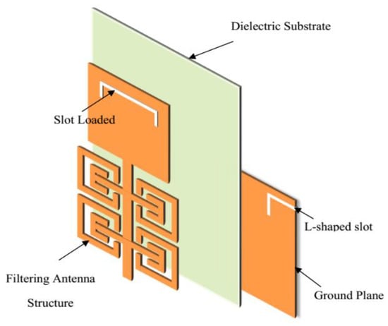
Figure 1.
Filter-antenna structure layout.
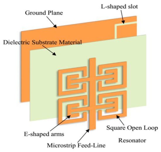
Figure 2.
Four-pole band-pass filter structure layout.
The filtering antenna was established on three different types of dielectric substrate material, which are FR-4, RT/Duroid 5880, and RO3003. Firstly, these substrate materials were kept at a fixed thickness, and then the thickness of each dielectric substrate was changed to investigate which of these three types is more suitable for the specifications of a certain application. The absorption of electrical energy by a dielectric material that is exposed to an alternating electric field is called dielectric loss.
Dielectric loss results from the influence of the limited loss tangent (tanδ), in which the losses are increasing and directly proportional to the operating frequency. Generally, the dielectric constant of the substrate εr is a complex number and is given by:
where is the real part of the dielectric constant and is the imaginary part of the dielectric constant.
Then, the loss tangent is given by [41]:
The relationship between the tangent loss and dielectric loss is given by the following formula [42]:
where is a dielectric loss, is a free-space wavelength, and represents the effective dielectric constant of the substrate material and is given by:
where W is the width of the patch.
Figure 3 shows the dielectric loss for the three types of substrates that are used in this article. The microstrip propagation delay tpd is a function of a substrate dielectric constant εr and can be given by:
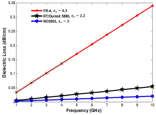
Figure 3.
Dielectric loss versus frequency for different types of substrate materials at h/w = 0.04.
Attenuation sources of practical microstrip lines can be raised due to the effect of the radiation mechanism and the finite conductivity of the transmission lines. The energy in the microstrip line depends on the dielectric constant εr, substrate thickness (h), and the circuit geometry. Using a low dielectric constant substrate, which has low concentration energy, leads to high radiation losses. Figure 4 shows the relationship between the propagation delay and the dielectric constant for different types of dielectric substrates. Figure 5 shows the final filter-antenna structure with its optimised dimensions, as illustrated in Table 1. It can be seen that the structure has four open-loop resonators connected to the microstrip feed-line and established on a dielectric substrate material with a defected ground plane that has an L-shaped slot.
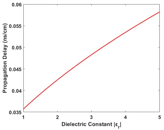
Figure 4.
Propagation delay versus dielectric constant.
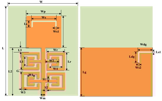
Figure 5.
The proposed filter-antenna structure with its optimised dimensions.

Table 1.
The optimised dimensions of the proposed filtering antenna (in mm).
4. Simulation and Measurement Results
The microstrip filter-antenna is designed at a centre frequency f0 = 2.4 GHz, and bandwidth edges f1 = 1.80 GHz and f2 = 3.10 GHz. The proposed filter-antenna is suitable for 2.4 GHz ISM band and 4G wireless communications applications. Its relatively high bandwidth fits fast data transmission systems, which is required in modern and future wireless communications. Figure 6 shows the frequency response characteristics of the introduced filter-antenna without L-shaped defected ground structure (DGS).
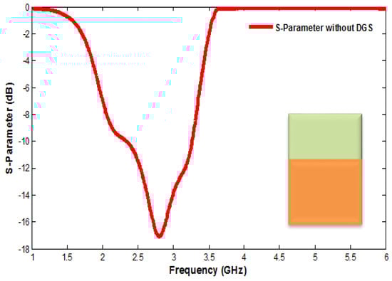
Figure 6.
S11 of the proposed filter-antenna without defected ground structure (DGS).
Etching the DGS in the ground plane of the filter-antenna disturbs the current field distribution in a waveguide structure. This disturbance will affect the parameters of the design, such as the effective capacitance and effective inductance [43]. The feature of DGS is a slow-wave impact due to the equivalent LC components that may decrease the designed circuit size [44]. Figure 7 shows the simulated frequency response of the proposed filter-antenna design without a square open-loop ring resonator (SOLR).
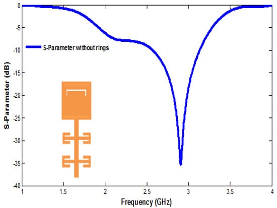
Figure 7.
S11 of the filtering antenna without a square open-loop ring resonator (SOLR).
Furthermore, a performance comparison of the reflection coefficient parameters for three types of dielectric substrate materials at a fixed substrate height (h = 0.8 mm) is presented in Figure 8. It should be noted that the dielectric substrate material has a significant effect on the design performance, especially the centre frequency and reflection coefficient characteristics. Table 2 explains the performance comparison of the three different dielectric substrate types for which the filter-antenna is designed and proposed.

Figure 8.
Comparison of S11 for different dielectric substrate materials at h = 0.81 mm.
Table 2.
Comparison of different parameters for three different dielectric substrate materials.
Figure 9 shows the comparison of the reflection coefficient parameters for three different dielectric substrate materials on which the filtering antenna design is established for different substrate heights. These comparisons are necessary to illustrate the effect of the dielectric substrate material type and thickness. Table 3 shows the comparison of some of the important parameters involved in the designed filter-antenna circuit on the three different dielectric substrate material types.
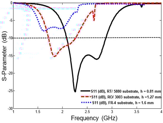
Figure 9.
S11 comparison for different dielectric substrate materials and different dielectric substrate heights.
Table 3.
Performance comparison of some of the parameters involved in the designed filter-antenna circuit using the three different dielectric substrate material types.
Figure 10 shows the simulated and measured reflection coefficient (S11) and gain for the proposed filter-antenna with the practical realisation for the prototype, which is fabricated using RT/Duroid 5880 dielectric substrate with a height of 0.81 mm and a dielectric constant of 2.2. The structure is printed on a compact size of 0.32 λ0 × 0.30 λ0, where λ0 is the free-space wavelength at the centre frequency. From Figure 6, Figure 7, and Figure 10, it should be noted that there is a significant and noticeable effect of the DGS and the SOLR on the overall performance of the filter-antenna response. The designed filter-antenna operates at a centre frequency of 2.4 GHz and has a relatively wide-band impedance bandwidth of about 1.22 GHz and a fractional bandwidth (FBW) of about 50%. The measurement results show the design also has a maximum realised gain of 4.9 dB at the operating frequency.
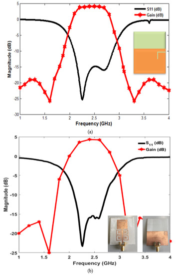
Figure 10.
The performance of the proposed filter-antenna design: (a) simulated performance, (b) measured performance with a photograph of the fabricated prototype structure.
Moreover, Figure 11 shows the simulated and measured far-field radiation patterns of the proposed filter-antenna design at a centre frequency f0 = 2.4 GHz. It is clear that the design offers stable and good radiation patterns at phi = 0 and 90 degrees. The simulation results from the CST simulator and the measurement results from the vector network analyzer (HP 8510C) and the anechoic chamber [41] show a reasonably good agreement.
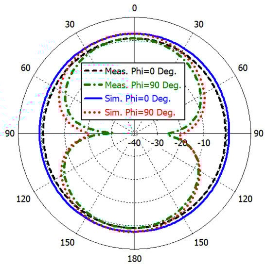
Figure 11.
The far-field radiation patterns for the proposed filter-antenna design.
Table 4 shows a performance comparison between the proposed microstrip filter-antenna and some designs from the literature that have similar structures and performances. The proposed filter-antenna design has a compact size with a simple structure; it offers higher gain, wider fractional bandwidth, and good reflection coefficient characteristics.
Table 4.
Comparison between the proposed design and others.
5. Conclusions
This article presents a compact wide-band microstrip filter-antenna design for 2.4 GHz ISM band and 4G wireless communications. The filter-antenna has been designed, measured, and studied in three different dielectric substrate materials, which are Rogers RT5880, Rogers RO3003, and FR-4. The analysis was performed by using CST microwave studio software. A performance comparison for the designed filter-antenna with different dielectric substrate materials and heights has been presented and discussed using the same design configuration. The results obtained from each design indicate that the most suitable characteristics for a specific application can be achieved by using Rogers RT5880 dielectric substrate material. According to the results, a filtering antenna that consists of a four-pole band-pass filter, integrated with a monopole patch antenna, was designed, fabricated, and measured. The simulation results generated by using the CST software package and the measurement achieved by using a vector network analyzer and an anechoic chamber show a reasonably good agreement.
Author Contributions
Conceptualisation, Y.I.A.A.-Y., H.A.A. and M.K.A.; methodology, Y.I.A.A.-Y. and N.O.P.; investigation, Y.I.A.A.-Y., M.K.A., I.E., J.R., A.L.S. and R.A.A.-A.; resources, Y.I.A.A.-Y., N.O.P, M.K.A. and R.A.A.-A.; writing—original draft preparation, Y.I.A.A.-Y., H.A.A., M.K.A., A.L.S., I.E., R.A.A.-A. and J.R.; writing—review and editing, Y.I.A.A.-Y., H.A.A., N.O.P. and I.E.; visualisation, Y.I.A.A.-Y., M.K.A., I.E., R.A.A.-A. and J.R. All authors have read and agreed to the published version of the manuscript.
Funding
This project has received funding from the European Union’s Horizon 2020 research and innovation programme under grant agreement H2020-MSCA-ITN-2016 SECRET-722424.
Acknowledgments
The authors wish to express their thanks for the support provided by the innovation programme under grant agreement H2020-MSCA-ITN-2016 SECRET-722424.
Conflicts of Interest
The authors declare no conflict of interest.
References
- Hussaini, A. Green Flexible RF for 5G. In Fundamentals of 5G Mobile Networks, 1st ed.; Rodriguez, J., Ed.; John Wiley and Sons: Hoboken, NJ, USA, 2015. [Google Scholar]
- Rodriguez, J.; Radwan, A.; Barbosa, C.; Fitzek, F.H.P.; Abd-Alhameed, R.A.; Noras, J.M.; Jones, S.M.R.; Politis, I.; Galiotos, P.; Schulte, G.; et al. SECRET—Secure Network Coding for Reduced Energy next Generation Mobile Small Cells: A European Training Network in Wireless Communications and Networking for 5G. In Proceedings of the 2017 Internet Technologies and Applications (ITA), Wrexham, UK, 12–15 September 2017; pp. 329–333. [Google Scholar]
- Parchin, N.O. Microwave/RF Components for 5G Front-End Systems; AVID SCIENCE: Telangana, India, 2020. [Google Scholar]
- Al-Yasir, Y.; Abd-Alhameed, R.A.; Noras, J.M.; Abdulkhaleq, A.M.; Ojaroudi, N. Design of Very Compact Combline Band-Pass Filter for 5G Applications. In Proceedings of the Loughborough Antennas & Propagation Conference (LAPC), Loughborough, UK, 12–13 November 2018; pp. 1–4. [Google Scholar]
- Abdulraheem, Y.I.; Abdullah, A.; Mohammed, H.; Abd-Alhameed, R.; Noras, J. Design of Frequency reconfigurable Multiband Compact Antenna using two PIN diodes for WLAN/WiMAX Applications. IET Microw. Antennas Propag. 2017, 11, 1098–1105. [Google Scholar] [CrossRef]
- Al-Yasir, Y.I.A.; Tu, Y.; Bakr, M.S.; Parchin, N.O.; Asharaa, A.S.; Mshwat, W.A.; Abd-Alhameed, R.A.; Noras, J.M. Design of multi-standard single/tri/quint-wideband asymmetric stepped-impedance resonator filters with adjustable TZs. IET Microw. Antennas Propag. 2019, 13, 1637–1645. [Google Scholar] [CrossRef]
- Liu, H.; Ren, B.P.; Li, S.; Guan, X.H.; Wen, P.; Peng, X.X.Y. High-Temperature Superconducting Bandpass Filter Using Asymmetric Stepped-Impedance Resonators with Wide-Stopband Performance. IEEE Trans. Appl. Supercond. 2015, 25, 1–6. [Google Scholar]
- Al-Yasir, Y.I.A.; Tu, Y.; Parchin, N.O.; Abdulkhaleq, A.; Kosha, J.; Ullah, A.; Abd-Alhameed, R.; Noras, J. New Multi-standard Dual-Wideband and Quad-Wideband Asymmetric Step Impedance Resonator Filters with Wide Stop Band Restriction. Int. J. RF Microw. Comput. Aided Eng. 2019, 29, e21802. [Google Scholar] [CrossRef]
- Al-Yasir, Y.I.A.; Tu, Y.; Parchin, N.O.; Elfergani, I.; Abd-Alhameed, R.; Rodriguez, J.; Noras, J. Mixed-coupling multi-function quint-wideband asymmetric stepped impedance resonator filter. Microw. Opt. Tech. Lett. 2019, 61, 1181–1184. [Google Scholar] [CrossRef]
- Mohammed, H.J.; Abdulsalam, F.; Abdulla, A.S.; Ali, R.S.; Abd-Alhameed, R.A.; Noras, J.M.; Abdulraheem, Y.I.; Ali, A.; Rodriguez, J.; Abdalla, A.M. Evaluation of genetic algorithms, particle swarm optimisation, and firefly algorithms in antenna design. In Proceedings of the 13th International Conference on Synthesis, Modeling, Analysis and Simulation Methods and Applications to Circuit Design (SMACD), Lisbon, Portugal, 27–30 June 2016; pp. 1–4. [Google Scholar]
- Hou, Z.; Liu, C.; Zhang, B.; Song, R.; Wu, Z.; Zhang, J.; He, D. Dual-/Tri-Wideband Bandpass Filter with High Selectivity and Adjustable Passband for 5G Mid-Band Mobile Communications. Electronics 2020, 9, 205. [Google Scholar] [CrossRef]
- Al-Yasir, Y.I.A.; Ojaroudi Parchin, N.; Abdulkhaleq, A.M.; Bakr, M.S.; Abd-Alhameed, R.A. A Survey of Differential-Fed Microstrip Bandpass Filters: Recent Techniques and Challenges. Sensors 2020, 20, 2356. [Google Scholar] [CrossRef]
- Al-Yasir, Y.I.A.; Parchin, N.O.; Abdulkhaleq, A.; Abd-Alhameed, R.; Noras, J. Recent Progress in the Design of 4G/5G Reconfigurable Filters. Electronics 2019, 8, 114. [Google Scholar] [CrossRef]
- Ghouz, H.H.M.; Sree, M.F.A.; Ibrahim, M.A. Novel Wideband Microstrip Monopole Antenna Designs for WiFi/LTE/WiMax Devices. IEEE Access 2020, 8, 9532–9539. [Google Scholar] [CrossRef]
- Lu, J.; Zhang, H.C.; He, P.H.; Zhang, L.P.; Cui, T.J. Design of Miniaturized Antenna Using Corrugated Microstrip. IEEE Trans. Antennas Propag. 2020, 68, 1918–1924. [Google Scholar] [CrossRef]
- Al-Yasir, Y.; Abdullah, A.; Ojaroudi Parchin, N.; Abd-Alhameed, R.; Noras, J. A New Polarization-Reconfigurable Antenna for 5G Applications. Electronics 2018, 7, 293. [Google Scholar] [CrossRef]
- Yasir, I.A.A.; Hasanain, A.H.A.; Baha, A.S.; Parchin, N.O.; Ahmed, M.A.; Abdulkareem, S.A.; Raed, A.A. New Radiation Pattern-Reconfigurable 60-GHz Antenna for 5G Communications. IntechOpen 2019. Available online: https://www.intechopen.com/online-first/new-radiation-pattern-reconfigurable-60-ghz-antenna-for-5g-communications (accessed on 26 September 2019).
- Ogurtsov, S.; Koziel, S. A Conformal Circularly Polarized Series-Fed Microstrip Antenna Array Design. IEEE Trans. Antennas Propag. 2020, 68, 873–881. [Google Scholar] [CrossRef]
- Al-Yasir, Y.I.A.; Parchin, N.O.; Abdulkhaleq, A.; Hameed, K.; Al-Sadoon, M.; Abd-Alhameed, R. Design, Simulation and Implementation of Very Compact Dual-band Microstrip Bandpass Filter for 4G and 5G Applications. In Proceedings of the 16th International Conference on Synthesis, Modeling, Analysis and Simulation Methods and Applications to Circuit Design (SMACD), Lausanne, Switzerland, 15–18 July 2019; pp. 41–44. [Google Scholar]
- Yang, D.; Zhai, H.; Guo, C.; Li, H. A Compact Single-Layer Wideband Microstrip Antenna with Filtering Performance. IEEE Antennas Wirel. Propag. Lett. 2020, 19, 801–805. [Google Scholar] [CrossRef]
- Khan, A.; Nema, R. Analysis of Five Different Dielectric Substrates on Microstrip Patch Antenna. Int. J. Comput. Appl. 2012, 55, 40–47. [Google Scholar] [CrossRef]
- Chuang, C.-T.; Chung, S.-J. A new compact filtering antenna using defected ground resonator. In Proceedings of the Microwave Conference Proceedings (APMC), 2010 Asia-Pacific, Yokohama, Japan, 7–10 December 2010; pp. 1003–1006. [Google Scholar]
- Coonrod, J. Choosing Circuit Materials for Millimeter-Wave Applications. High Freq. Electron. 2013, 3, 22–30. [Google Scholar]
- Cui, J.; Zhang, A.; Yan, S. Co-design of a filtering antenna based on multilayer structure. Int. J. RF Microw. Comput. Aided Eng. 2020, 30, e22096. [Google Scholar] [CrossRef]
- Hua, C.; Liu, M.; Lu, Y. Planar integrated substrate integrated waveguide circularly polarized filtering antenna. Int. J. RF Microw. Comput. Aided Eng. 2019, 29, e21517. [Google Scholar] [CrossRef]
- Al-Yasir, Y.I.A.; Parchin, N.O.; Alabdallah, A.; Abdulkhaleq, A.M.; Abd-Alhameed, R.A.; Noras, J.M. Noras, Design of Bandpass Tunable Filter for Green Flexible RF for 5G. In Proceedings of the 2019 IEEE 2nd 5G World Forum (5GWF), Dresden, Germany, 30 September–2 October 2019. [Google Scholar]
- Niu, B.; Tan, J.-H. Dipole filtering antenna with quasi-elliptic peak gain response using parasitic elements. Microw. Opt. Technol. Lett. 2019, 61, 1612–1616. [Google Scholar] [CrossRef]
- Park, J.; Jeong, M.-J.; Hussain, N.; Rhee, S.; Park, S.; Kim, N. A low-profile high-gain filtering antenna for fifth generation systems based on nonuniform metasurface. Microw. Opt. Technol. Lett. 2019, 61, 2513–2519. [Google Scholar] [CrossRef]
- Al-Yasir, Y.I.A.; Parchin, N.O.; Abd-Alhameed, R.A. A Differential-Fed Dual-Polarized High-Gain Filtering Antenna Based on SIW Technology for 5G Applications. In Proceedings of the 14th European Conference on Antennas and Propagation (EuCAP), Copenhagen, Denmark, 15–20 March 2020; pp. 1–5. [Google Scholar]
- Song, L.; Wu, B.; Xu, M.; Su, T.; Lin, L. Wideband balun filtering quasi-Yagi antenna with high selectivity. Microw. Opt. Technol. Lett. 2019, 61, 2336–2341. [Google Scholar] [CrossRef]
- Wu, W.; Fan, R.; Wang, J.; Zhang, Q. A broadband low profile microstrip filter-antenna with an omni-directional pattern. In Proceedings of the 2014 3rd Asia-Pacific Conference on Antennas and Propagation, Harbin, China, 26–29 July 2014; pp. 580–582. [Google Scholar]
- Lin, C.; Chung, S. A Compact Filtering Microstrip Antenna with Quasi-Elliptic Broadside Antenna Gain Response. IEEE Antennas Wirel. Propag. Lett. 2011, 10, 381–384. [Google Scholar]
- Wu, W.; Ma, B.; Wang, J.; Wang, C. Design of a microstrip antenna with filtering characteristics for wireless communication systems. In Proceedings of the 2017 Sixth Asia-Pacific Conference on Antennas and Propagation (APCAP), Xi’an, China, 16–19 October 2017; pp. 1–3. [Google Scholar]
- Al-Yasir, Y.I.A.; Parchin, N.O.; Abd-Alhameed, R.A. New High-Gain Differential-Fed Dual-Polarized Filtering Microstrip Antenna for 5G Applications. In Proceedings of the 14th European Conference on Antennas and Propagation (EuCAP), Copenhagen, Denmark, 15–20 March 2020; pp. 1–5. [Google Scholar]
- Wu, W.; Yin, Y.; Zuo, S.; Zhang, Z.; Xie, J. A New Compact Filter-Antenna for Modern Wireless Communication Systems. IEEE Antennas Wirel. Propag. Lett. 2011, 10, 1131–1134. [Google Scholar]
- Ohira, M.; Ma, Z. An efficient design method of microstrip filtering antenna suitable for circuit synthesis theory of microwave band-pass filters. In Proceedings of the 2015 International Symposium on Antennas and Propagation (ISAP), Hobart, TAS, Australia, 9–12 November 2015; pp. 1–4. [Google Scholar]
- Al-Yasir, Y.I.A.; Alhamadani, H.A.; Kadhim, A.S.; Ojaroudi Parchin, N.; Saleh, A.L.; Elfergani, I.T.E.; Rodriguez, J.; Abd-Alhameed, R.A. Design of a Wide-Band Microstrip Filtering Antenna with Modified Shaped Slots and SIR Structure. Inventions 2020, 5, 11. [Google Scholar] [CrossRef]
- Leys, D. Best materials for 3–6 GHz design. Print. Circuit Des. Manuf. 2004, 34–39. [Google Scholar]
- Khare, A.; Nema, R.; Gour, P.; Thakur, R.K. New multiband E-shape microstrip patch antenna on RT DUROID 5880 substrate and RO4003 substrate for pervasive wireless communication. Int. J. Comput. Appl. 2010, 975, 8887. [Google Scholar] [CrossRef]
- Afrin, S.S.; Dev, P.R. Performance Analysis of Microstrip Patch Antenna for Ultra Wide Band Application; East West University: Dhaka, Bangladesh, 2015. [Google Scholar]
- Szostak, F.K.; Słobodzian, P. Broadband Dielectric Measurement of PCB and Substrate Materials by Means of a Microstrip Line of Adjustable Width. IEEE Microw. Wirel. Compon. Lett. 2018, 1, 945–947. [Google Scholar] [CrossRef]
- Kapusuz, K.; Lemey, S.; Rogier, H. Substrate-Independent Microwave Components in Substrate Integrated Waveguide Technology for High-Performance Smart Surfaces. IEEE Trans. Microw. Theory Tech. 2018, 1, 3036–3047. [Google Scholar] [CrossRef]
- Breed, G. An introduction to defected ground structures in microstrip circuits. High Frequency Electron. 2008, 7, 50–54. [Google Scholar]
- Mahmud, F.S.; Razalli, M.S.; Rahim, H.A.; Hoon, W.F.; Ilyas, M.Z. Parametric studies on effects of defected ground structure (DGS) for dual band bandstop microstrip filter. EPJ Web Conf. 2017, 1, 1–5. [Google Scholar] [CrossRef]


© 2020 by the authors. Licensee MDPI, Basel, Switzerland. This article is an open access article distributed under the terms and conditions of the Creative Commons Attribution (CC BY) license (http://creativecommons.org/licenses/by/4.0/).