Article

A Network Adaptive Fault-Tolerant Routing Algorithm for Demanding Latency and Throughput Applications of Network-on-a-Chip Designs

1
Department of Information and Communication Engineering, Yeungnam University, Gyeongsan 38541, Korea
2
School of Intelligent Mechatronics Engineering, Sejong University, Seoul 05006, Korea
3
Department of Computer Science, COMSATS University Islamabad, Wah Campus, Wah Cantt 47040, Pakistan
*
Author to whom correspondence should be addressed.
Electronics 2020, 9(7), 1076; https://doi.org/10.3390/electronics9071076
Submission received: 14 May 2020 / Revised: 25 June 2020 / Accepted: 27 June 2020 / Published: 1 July 2020

Abstract

:
Scalability is a significant issue in system-on-a-chip architectures because of the rapid increase in numerous on-chip resources. Moreover, hybrid processing elements demand diverse communication requirements, which system-on-a-chip architectures are unable to handle gracefully. Network-on-a-chip architectures have been proposed to address the scalability, contention, reusability, and congestion-related problems of current system-on-a-chip architectures. The reliability appears to be a challenging aspect of network-on-a-chip architectures because of the physical faults introduced in post-manufacturing processes. Therefore, to overcome such failures in network-on-a-chip architectures, fault-tolerant routing is critical. In this article, a network adaptive fault-tolerant routing algorithm is proposed, where the proposed algorithm enhances an efficient dynamic and adaptive routing algorithm. The proposed algorithm avoids livelocks because of its ability to select an alternate outport. It also manages to bypass congested regions of the network and balances the traffic load between outports that have an equal number of hop counts to its destination. Simulation results verified that in a fault-free scenario, the proposed solution outperformed a fault-tolerant XY by achieving a lower latency. At the same time, it attained a higher flit delivery ratio compared to the efficient dynamic and adaptive routing algorithm. Meanwhile, in the situation of a faulty network, the proposed algorithm could reach a higher flit delivery ratio of up to 18% while still consuming less power compared to the efficient dynamic and adaptive routing algorithm.

1. Introduction

The contracting size of transistors to submicron levels leads to a large number of cores combined onto a chip known as a system-on-a-chip (SoC). The bus-based architectures of SoCs are not able to meet the growing diverse communication requirements. According to Moore’s law, the doubled packing density of micron technology is achievable every eighteen months. SoC architectures are unable to exploit the availability of these doubled PEs after every eighteen months due to latency and power nightmares [1].
Network-on-a-chip (NoC) architectures have evolved to overcome these growing challenges experienced by SoC architectures. An NoC’s communication is based on packet routing networks instead of the wires and busses used in SoC. NoC architectures are used to provide the advantages of reduced power, scalability, lower electromagnetic effects, and lower latency. In an NoC, communication is done via packet switching. These packets are further subdivided into smaller chunks called flits, where these flits are delivered via intermediary nodes to their desired destination. Routing algorithms are responsible for deciding the path to follow from a source to the final destination for these flits. This decision is dependent on the location of these PEs and the underlying network topology. In the literature, multiple topologies have been proposed, such as a mesh (two-dimensional (2D) and three-dimensional (3D) [2]), torus, honeycomb [3], butterfly, and hypercube [4,5,6].
The routing algorithms of NoCs are mainly arranged into three groups that are deterministic, partially/moderately adaptive, and fully/completely adaptive. Among these, routing algorithms in the deterministic category are not robust. They select predetermined paths between every sender and receiver node. To handle livelocks and deadlocks in the network, they restrict a few turns [7]. Deterministic routing algorithms are simple and straightforward. In contrast, the algorithms in the partly adaptive category send flits through distant alternative available routes depending upon the underlying network conditions of those routes; this classification aims to strike a balance between the router’s performance and its complex implementation. Finally, the algorithms in the completely adaptive category adapt themselves to the ever-changing network circumstances. This category does not consistently follow a predetermined route. In fact, the route is chosen on the fly depending upon the underlying network situation by considering faults, business, congestion, and hot-spots. The flit’s routing is also influenced by the switching mechanism employed by the network. A few of the established switching approaches include store and forwarding, wormhole, virtual cut-through, and circuit switching [8].
NoCs are also prone to radiation and temperature variations. These variations in radiation and temperature may cause transient or permanent faults, reducing NoCs’ reliability, notably in extreme environments. To achieve reliability, fault-tolerant routing algorithms in NoCs avoid faulty channels while computing the next hop. Hence, for NoCs, adaptive mechanisms are essential to prevent faults [9].
This study aimed to propose a network adaptive fault-tolerant routing (NAFTR) algorithm for the throughput and latency-critical NoC interconnections, where latency and throughput are the pivotal parameters. NAFTR extends the efficient dynamic and adaptive routing (EDAR) algorithm [10]. The main contributions of this article can be summarized as follows:
  • The proposed NAFTR algorithm decreased the latency in fault-free scenarios by avoiding the congested regions in the network.
  • When there was a tie between two outports in terms of having a similar hop count toward a destination, the NAFTR algorithm ensured load balancing regarding route selection.
  • Moreover, the NAFTR algorithm increased the flit delivery ratio by selecting alternate outports to avoid livelocks in the network.
The rest of the article is organized as follows. Section 2 summarizes the related research articles. The problem statement is formulated in Section 3. Section 4 briefly describes the proposed solution. Section 5 presents the experimental findings of this study. The article is concluded in Section 6.

2. Related Research

Many research works have proposed efficient routing mechanisms for NoC architectures. XY is a non-adaptive routing scheme [11] and is well known because of its simplicity in NoC architecture. In the XY algorithm, packets are always first routed to the horizontal plane and then to the vertical plane to reach its destination. This algorithm invariably routes packets via the shortest route. However, the XY algorithm is not able to avoid busy and congested links. Deterministic/partially adaptive routing algorithms [12] route packets while considering predetermined restricted turns to avoid livelocks and deadlocks in the network. Figure 1 depicts all the restricted turns in deterministic and partially adaptive routing algorithms. Negative first, north last, and west first have two restricted turns while odd even (OE) and XY have four restricted turns to avoid livelocks and deadlocks in the network.
On the other hand, fully adaptive routing algorithms dynamically adapt according to the network conditions. These algorithms add some virtual or physical channels to attain deadlock-free communication [13,14]. Various fault-tolerant routing algorithms have been proposed [15]. A partially adaptive fault-tolerant routing algorithm built on a negative-first approach is proposed in Glass and Ni [16]. However, in multiple faulty node scenarios, this algorithm does not perform efficiently. Another partially adaptive fault-tolerant routing algorithm is proposed in Wu [17], which is an enhanced version of the odd-even routing algorithm. An analogous algorithm, pertinent to the partially adaptive category, is proposed in References [18,19]. Numerous other research works have also utilized virtual channels to achieve fault-tolerance in NoCs [20,21]. The major drawback of virtual channel usage is the addition of the extra logic circuitry required for their implementation. Larger logical circuits yield an increased probability of faults occurring in the network, along with extra power requirements to operate them.
An adaptive fault-tolerant routing algorithm, which employs table-based routing for delivering packets from a particular source to the destination, is proposed in Schonwald et al. [22]. This algorithm is an enhanced version of fully force-directed wormhole routing (FDWR). Every node maintains a routing table to perform route decisions when forwarding packets to other nodes in the network. This algorithm is unable to ensure in-order delivery of packets. Additionally, building and maintaining the routing table yields an extra control overhead. An adaptive fault-tolerant routing algorithm is proposed in Singh et al. [23] that considers faults up to two hops away when considering the route selection for a packet. However, this algorithm does not manage busyness or hot spot regions in the network. Based on adaptive route selection, a fault-tolerant scheme is proposed in Savio Tse et al. [24]; unfortunately, this algorithm also does not manage busyness and congested regions of the network.
Liu et al. proposed an efficient dynamic and adaptive routing (EDAR) algorithm [10]. For route calculations, EDAR considers busy, congested, and faulty links up to one hop away. However, because this route decision is based on the knowledge of only one hop away, this may point to a congested region, which results in a further delay. Moreover, EDAR assigns the same priority weight to outports with an equal number of hops to a destination. Thus, EDAR is restricted regarding load balancing between available paths with an equal number of hops. A hybrid fault-tolerant routing algorithm (HFTRA) was proposed by Bishnoi et al.; however, HFTRA requires additional network power and area overheads because of the additional virtual channels employed. Additionally, the proposed algorithm does not have the mechanism of fault identification [25]. Yang et al. [26] presented a fault-tolerant routing algorithm designed for a honeycomb-like topology. This algorithm does not cater for 2D/3D mesh topologies. Furthermore, Moriam et al. [27] designed an analytic approach to conduct the reliability assessment of adaptive routing algorithms of NoCs. Melo et al. [28] proposed a finite state machine (FSM)-based router controller. Their study focused on mitigating the error propagation rate in the router controller. They did not cater to business and congestion avoidance mechanisms in their proposed algorithm. Zhang et al. proposed an improved fault-tolerant routing algorithm [29]. Their study primarily focused on mitigating multiple packet diversions, which may result in livelocking. Unfortunately, they did not consider business and congestion avoidance scenarios in their proposed work. Low-power and high-performance adaptive routing for on-chip designs are proposed in Xiang and Pan [30]. The study focused on bypassing k hops to deliver the packet to the final destination in a fewer number of cycles. The study did not consider congestion and business avoidance mechanisms in their proposed solution. Another similar study focusing on reducing the hop count toward a destination via the use of specialized channels, known as a transmission line (TL), was proposed in Deb et al. [31]. This study also did not consider congestion and business avoidance mechanisms in their proposed algorithm. Song et al. proposed uniform-minimal-first (UMF) routing [32]. UMF alternatively selects between XYX and YXY routing. This alternate selection leads to load balancing of traffic across the network; however, this study unfortunately did not consider fault tolerance, congestion, or business avoidance in their proposed mechanism. Liu et al. [33] proposed a congestion-aware OE router, which employs fair arbitration for outport selection rather than random selection. This fair arbitration policy helps to obtain a lower latency and a higher throughput. This study is solely focused on congestion avoidance. Jin et al. proposed a history-aware-adaptive routing algorithm called HARE [34]. HARE intends to solve the end-point congestion problem by identifying head-of-line blocking flits in buffers. HARE achieves higher throughput and lower latency because of its ability to separate head-of-line blocking flits. The study did not consider fault and busy port avoidance in the proposed mechanism. Table 1 summarizes the state-of-the-art routing algorithms of NoCs. The comparison identifies the primary focus of each study, the supported network topology, the simulation platform, and whether the study utilizes virtual channels to handle faults in the network. The key features that are essential for a routing algorithm are simplicity, fault tolerance, congestion, and business awareness. We selected EDAR to be optimized because it is a routing algorithm that possesses all these key features. We further optimized EDAR to propose NAFTR. NAFTR achieved a lower latency and higher throughput compared to EDAR, as indicated by the results presented in the experimental results section.

3. Problem Statement

EDAR is a valuable choice among other proposed fault-tolerant routing algorithms because of its simplicity; this leads to implementation ease and reduced latency. Moreover, EDAR also avoids congested and busy channels, along with avoiding faulty channels in the network. However, this route decision is based on the knowledge of only one hop. Therefore, the packet may reach a congested region or, in a few scenarios, bring us to a node that re-transmits the packet backward. In the livelock depicted in Figure 2a, node 5 needs to send a few packets toward node 7. While at node 5, the east port has the smallest weight of 1 because it leads to the smallest route to the destination only two hops away, whereas the south and north ports lead to a four-hop route from node 5 to the destination; therefore, they are assigned a weight of 2 each. Meanwhile, the west port leads to the longest route to the destination, which is seven hops from the current node; therefore, it has the highest weight of 3. Thus, node 5 selects the east outport for the packet forwarding because of its lower weight. However, the following east port will lead the packet to node 6, which falls in the congested region. Although EDAR tries to follow the shortest path to the destination, it leads the packet to a congested region, which results in an additional delay before reaching the destination. Consider another scenario, shown in Figure 2b, where node 6 has some packets to send to node 7. The shortest path to the destination uses the east port from node 6. However, the east port of node 6 is congested. The weight of the east port becomes 4 because an additional weight of 3 is added for a congested port (1 + 3 = 4), and the north and south ports are assigned the same weight of 2 each because they have the same hop count to the destination. EDAR does not have a mechanism to balance the traffic load among outports with a similar number of hops toward a destination. Therefore, EDAR will not utilize the south port, and it will continue to select the north port until it is congested.

4. Proposed Solution

The 2D mesh is the most trivial topology used in NoCs. In this article, we have evaluated the proposed algorithm on a 2D mesh topology. Figure 3 depicts a traditional 2D mesh topology of an NoC, where each PE is linked to a router via a local port for communication. Each router is also connected to the available immediate next hop neighbors via west (W), east (E), south (S), and north (N) ports. Every PE is assigned an ID starting from 0. This ID is utilized to obtain the X and Y coordinates of a particular PE’s location inside of an NoC network. Equations (1) and (2) can be used to calculate the X and Y coordinates of a particular PE.
X c o o r d i n a t e = m o d ( I D , n o c o l u m n s )
Y c o o r d i n a t e = I D / n o c o l u m n s
NAFTR virtually breaks down the network into eight regions labeled from D1 to D8. This virtual network division depends on the location of the destination PE relative to the current PE. The packet forwarding is done depending on the region the destination PE is located in (from D1 to D8). For every region, i.e., from D1–D8, for a particular packet, all of the outports of the router are assigned with a preferred port (PP) number from PP1 to PP3. The port leading toward the shortest route to the destination is labeled as PP1, the ports leading toward the next shortest route are labeled as PP2, and the port leading toward the longest route is labeled as PP3. Figure 4 illustrates this virtual network division for an 8 × 8 NoC network. The whole network is virtually partitioned into eight regions labeled from D1 to D8. This virtual partitioning will be different for every current and destination PE pair. The current PE is the one that is in the process of making a forwarding decision for a particular packet. The current and source PEs can be the same, but this will not be true in all cases. At the green-colored source PE, the east port leads toward the shortest path to the destination PE; therefore, it is labeled as PP1. The south and north ports lead toward the next shortest route to the destination; therefore, they are marked as PP2. Similarly, the port leading toward the longest route to the destination is the west port; therefore, it is marked as PP3.

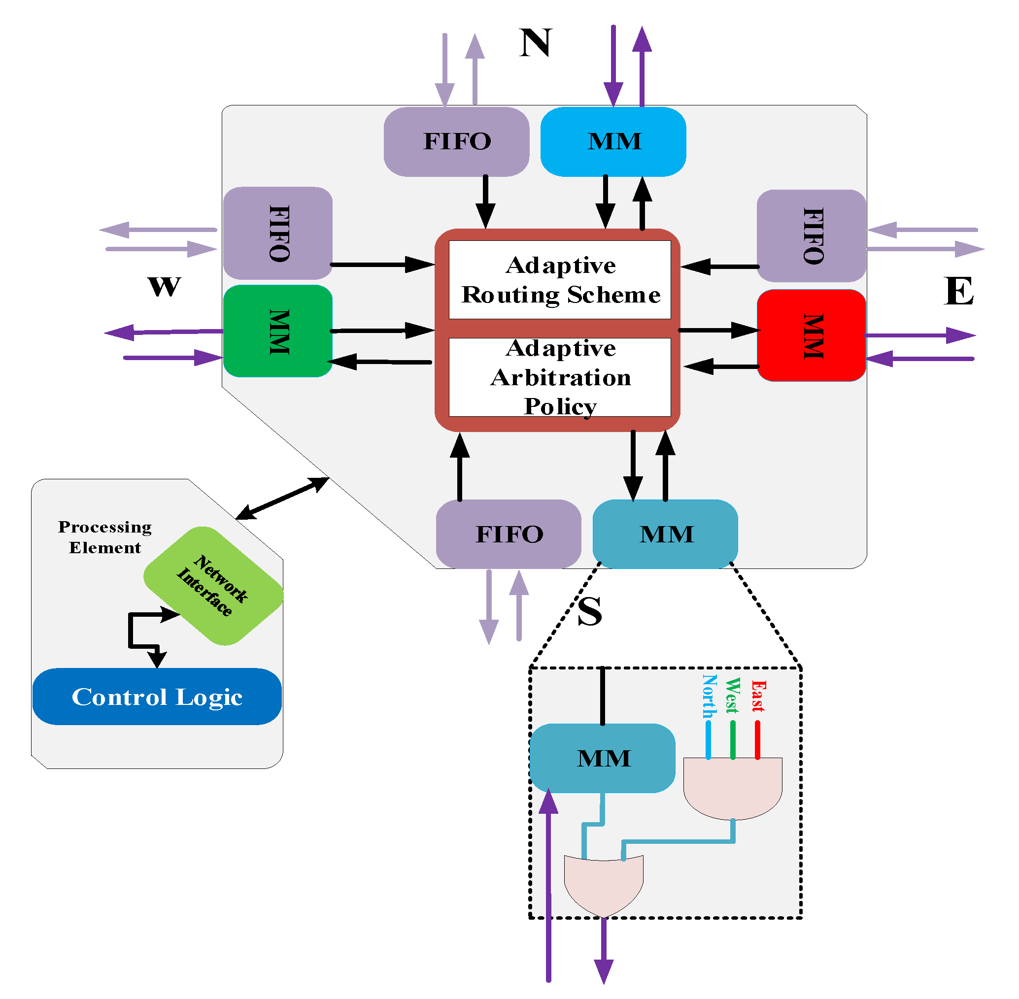
4.1. Modified EMBRACE Router Architecture

We have modified the emulating biologically-inspired architecture in hardware(EMBRACE) [35,36,37,38] router architecture. The EMBRACE router can detect busy, congested, and faulty channels efficiently. The modified EMBRACE router architecture is shown in Figure 5. A dotted black line surrounds the newly added components. Channel conditions, such as busy, congestion, and faults, are shared with the adaptive routing scheme (ARS). ARS utilizes this information for the packet-forwarding decision. Adaptive arbitration policy (AAP) handles simultaneous requests for a particular outport. AAP resolves conflicts via arbitration. AAP also handles the allocation of virtual channels. The monitor module (MM) is responsible for monitoring the channel condition of the neighboring node. MM outputs the appropriate signal depending upon the channel condition, i.e., busy, congested, or faulty. Four MMs are responsible for monitoring all four adjacent node channels. This signal from four MMs is conveyed to ARS as a faulty/congested/busy flag, which is required for the computation of the next outport. Outputs of all four MMs are connected via AAP. If all three outgoing channels of a node are congested, then MM declares its fourth incoming channel as congested to its immediate neighbor as well to avoid incoming packets entering into the congested region. To do so, one additional set of OR and AND gates are applied at every MM. Figure 6 shows a scenario to further clarify the operation of newly added AND and OR gates. Suppose that node 6 has its east, west, and south ports congested. Let us have a close look at the operation of the north port’s MM of the sixth node. The MM of the north port has all three inputs of the AND gate as 1 because the three other ports are congested. Now, the AND gate’s output becomes 1 as all three inputs are 1 but the north port is not congested; therefore, the north port’s MM output is 0. When this 0 and 1 are applied at the OR gate, its output becomes 1; therefore, node six will declare its incoming north port as congested to node 2 to avoid incoming packets from node 2 entering the congested region. Let us now have a look at the south port’s MM operation for the same node. In fact, the AND gate of the south port’s MM is given two 1’s and one 0 as the input because its east and west ports are congested but its north port is not congested. The output of the AND gate becomes 0. The output of the MM of the south port is 1 because the south port is congested; therefore, when this 1 and 0, i.e., the output of the AND gate is applied at the OR gate, its output also becomes 1. Therefore, either the current channel is congested or all three remaining channels are congested; therefore, the MM declares its current channels as congested. This enables the neighboring router to avoid the congested region. The modified EMBRACE router requires one additional OR and AND gate per port for this purpose.

4.2. NAFTR Algorithm

The key annotations are explained in Table 2 and the proposed algorithm’s working is illustrated via the pseudocode in Algorithm 1. The NAFTR algorithm performs the following defined steps while performing the packet forwarding decision.
Step 1: Compare the X and Y coordinates of the destination node with the current node. If they are equal, then send the packet toward the local outport. If they are not equal, then perform step 2.
Step 2: Assign the preferred port number from PP1–PP3 to all legitimate outports. This decision is based on which region the destination PE falls (region from D1–D8).
Step 3: Examine the condition of all legitimate outports. Assign a busy ( W b ) one with a weight of 2, a congested ( W c ) one with a weight of 3, and a faulty ( W f ) one with a weight of 10. Add W b , W p ,     W f , and W c together to get the final total weight for every legitimate outport.
Step 4: Search for the outport with the minimum total weight among all possible outports. If this outport is equivalent to the inport of the packet, then perform step number 5. Otherwise, forward the packet towards this outport.
Step 5: Search for the alternate outport leading toward the path with the second-lowest weight and forward the packet to that outport. If there are two possible candidates for the second-lowest total weight selection due to having the same hop count to the destination, then randomly select one outport among them. This random selection will ensure load balancing between outports having a similar distance in hops toward a destination.

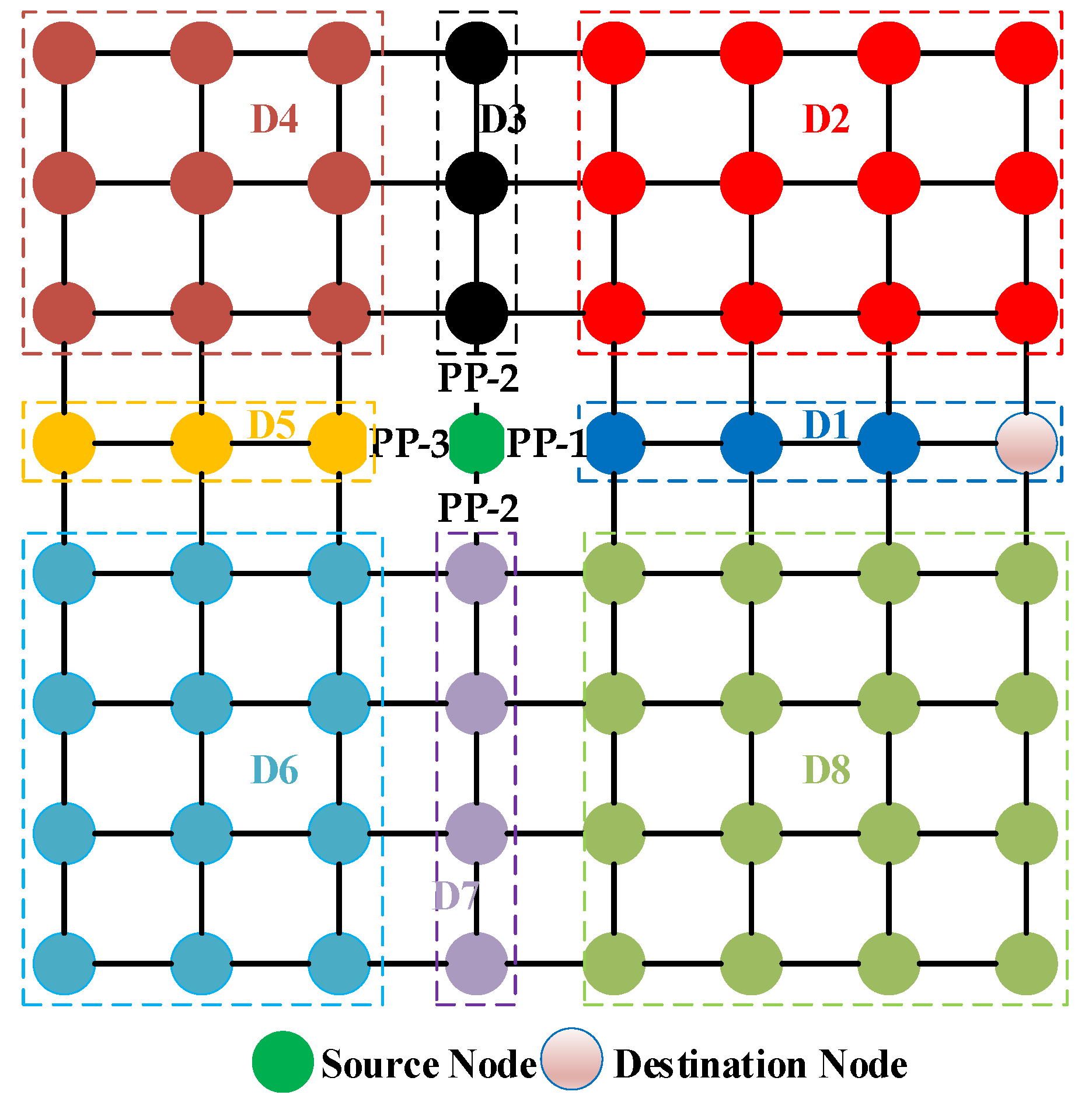
4.2.1. Latency Improvement Achieved Using NAFTR in Fault-Free Scenarios

NAFTR can lower the latency because of its ability to avoid congested regions. Let us revisit Figure 2a. Node 5 needs to send a few packets toward node 7. Three out of four outports of node 6 are congested; therefore, node 6 declares its west incoming port as congested. Now, the total weight of the east port at node 5 becomes 1 + 3 = 4. Therefore, node 5 selects the north port as the outport. This enables NAFTR to avoid congested regions in the network.

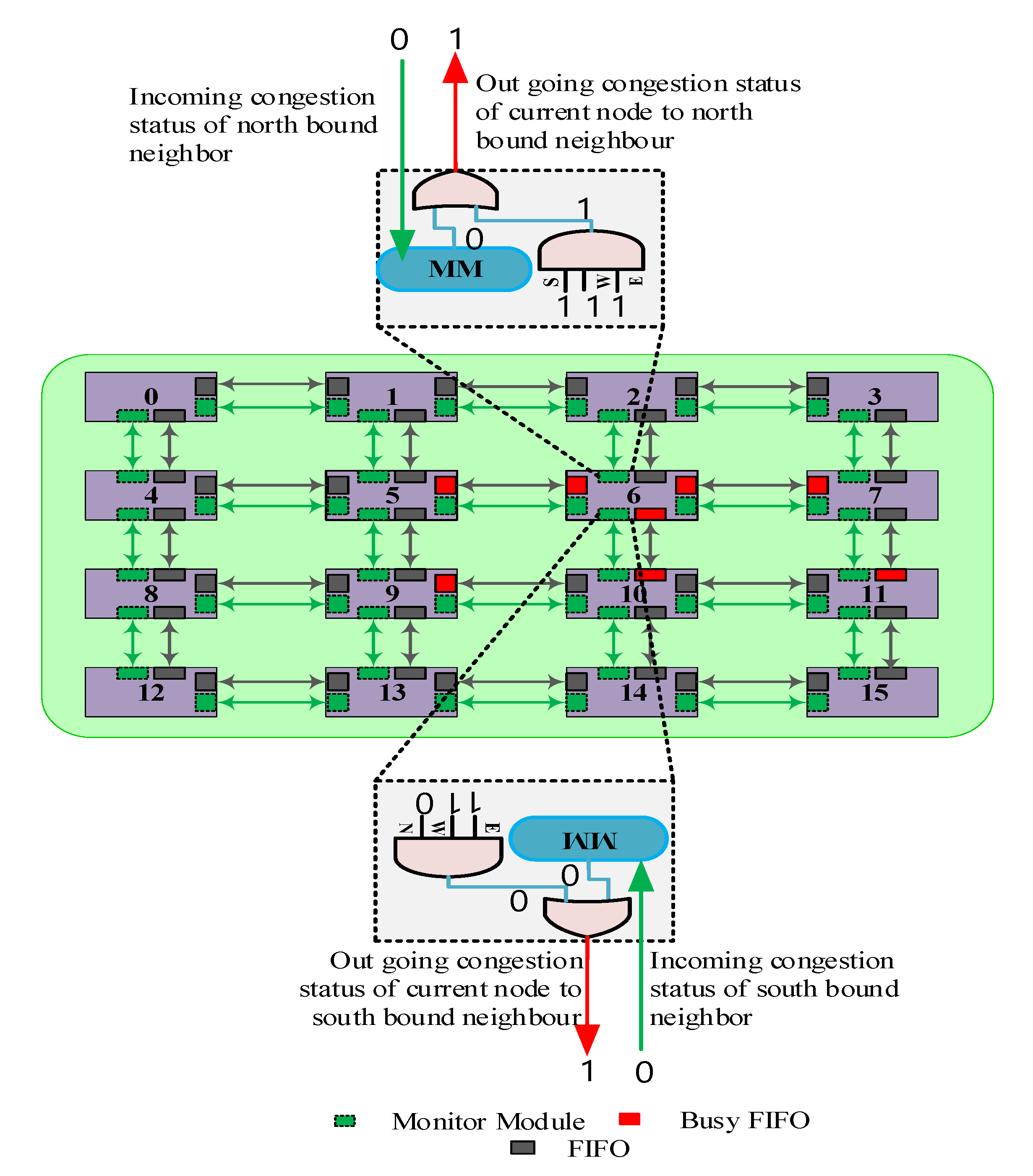
4.2.2. Load Balancing

EDAR assigns equal weights to outports with a similar hop distance toward a destination. It does not have a mechanism to break ties. EDAR selects the first port among those with the same hop count and continues to select that port until it is congested. This leads to congestion of one port all of the time and the other port not utilized to its full capabilities. NAFTR does not assign the same weight to all outports having the same hop distance toward a destination. Rather it randomly selects between two outports with a similar hop count. Thus, it distributes the share of traffic with equal probabilities among outports with a similar hop distance toward a destination.
Algorithm 1: Network-Adaptive Fault-Tolerant Routing (NAFTR) Algorithm
Input: n u m c o l s , DestinationID, CurrentID, S b , c , f [ N / E / S / W ] , In-port
Output: Chosen Out-portOutput
01procedure Determine_Next_Hop
02 Xcur= CurrentID / numcols, Ycur = CurrentID % numcols
03 Xdest= DestinationID / n u m c o l s , Ydest = DestinationID % n u m c o l s
04if ( X c u r == X d e s t && Y c u r == Y d e s t ) then
05return local port;
06end if
07 W p [4]=DPWC(x)
08for i=E to W do
09  if S c / b / f [ i ] equals 1 then
10       W c / b / f [ i ] =3/2/10
11    end if
12     W i [ i ] = W b [ i ] + W p [ i ] + W f [ i ] +   W c [ i ]
13 end for
14  Selected-port=Min-weigh-port-in W i [ i ]
15if Selected-port equals In-port then
16Out-port=Second_Min_Weigh_Port_in W i [ i ]
17else
18return Selected-port
19  end if
20   end procedure
01procedure DPWC(x)
02if (x==0) then
03  z1=0,z2=0.5
04else z1=0.5,z2=0
05if ( X d > X c   & &   Y d = = Y c ) then               //D1
06      W p [ N / E / S / W ] ={2+z1,1,2+z2,3} end if
07else if ( X d > X c   & &   Y d < Y c ) then               //D2
08      W p [ N / E / S / W ] ={2,1,3+z1,3+z2} end if
09else if ( X d = = X c   & &   Y d < Y c ) then              //D3
10      W p [ N / E / S / W ] ={1,2+z1,3,2+z2} end if
11else if ( X d < X c   & &   Y d < Y c ) then               //D4
12      W p [ N / E / S / W ] ={2,3+z1,3+z2,1} end if
13else if ( X d < X c   & &   Y d = = Y c ) then              //D5
14      W p [ N / E / S / W ] ={2+z1,3,2+z2,1} end if
15else if ( X d X c   & &   Y d Y c ) then               //D6
16      W p [ N / E / S / W ] ={3+z1,3+z2,2,1} end if
17else if ( X d = = X c   & &   Y d > Y c ) then              //D7
18      W p [ N / E / S / W ] ={3,2+z1,1,2+z2} end if
19else if ( X d > X c   & &   Y d > Y c ) then               //D8
20      W p [ N / E / S / W ] ={3+z1,1,2,3+z2} end if
21end procedure

4.2.3. Livelock/Deadlock Avoidance

The following assumptions were used in this paper for the avoidance of deadlock and livelock: (a) a packet is absorbed when it reaches a destination, (b) a node is not allowed to send a packet to itself, and (c) the source and destination PEs fall in a connected region. The strategies used to handle deadlocks are deadlock prevention, deadlock avoidance, and recovery. Using a virtual channel (VC) at the router falls under the category of deadlock avoidance [39]. The EMBRACE router architecture uses a VC to avoid deadlocks in the network. A VC is implemented as a first in, first out (FIFO) queue. When a packet enters a physical channel, it is assigned to the VC. This packet stays in the VC until the next computed outport is idle and ready to receive this packet. The router does not allow the VC assignment in a closed path/loop, which avoids deadlocks from happening in the network in the first place.
For livelock avoidance, a data packet coming from a given direction is not allowed to return in the same direction. NAFTR selects the outport with the next-lowest weight for packet forwarding if the shortest route toward a destination is the route from where the packet entered the router. Thus, the packet will eventually reach the destination, although it may experience a longer path delay in the process of avoiding congested regions. In the case of higher fault rates in the network, re-routing constraint mechanisms [40] may be applied, which constrains the maximum number of re-routings to be performed for a given packet. When the number of re-routings exceeds that threshold, the packet is discarded. This may raise concerns regarding the quality of service. In that case, an automated repeat request (ARQ) mechanism can be adopted to re-transmit the dropped packet through a different port number.

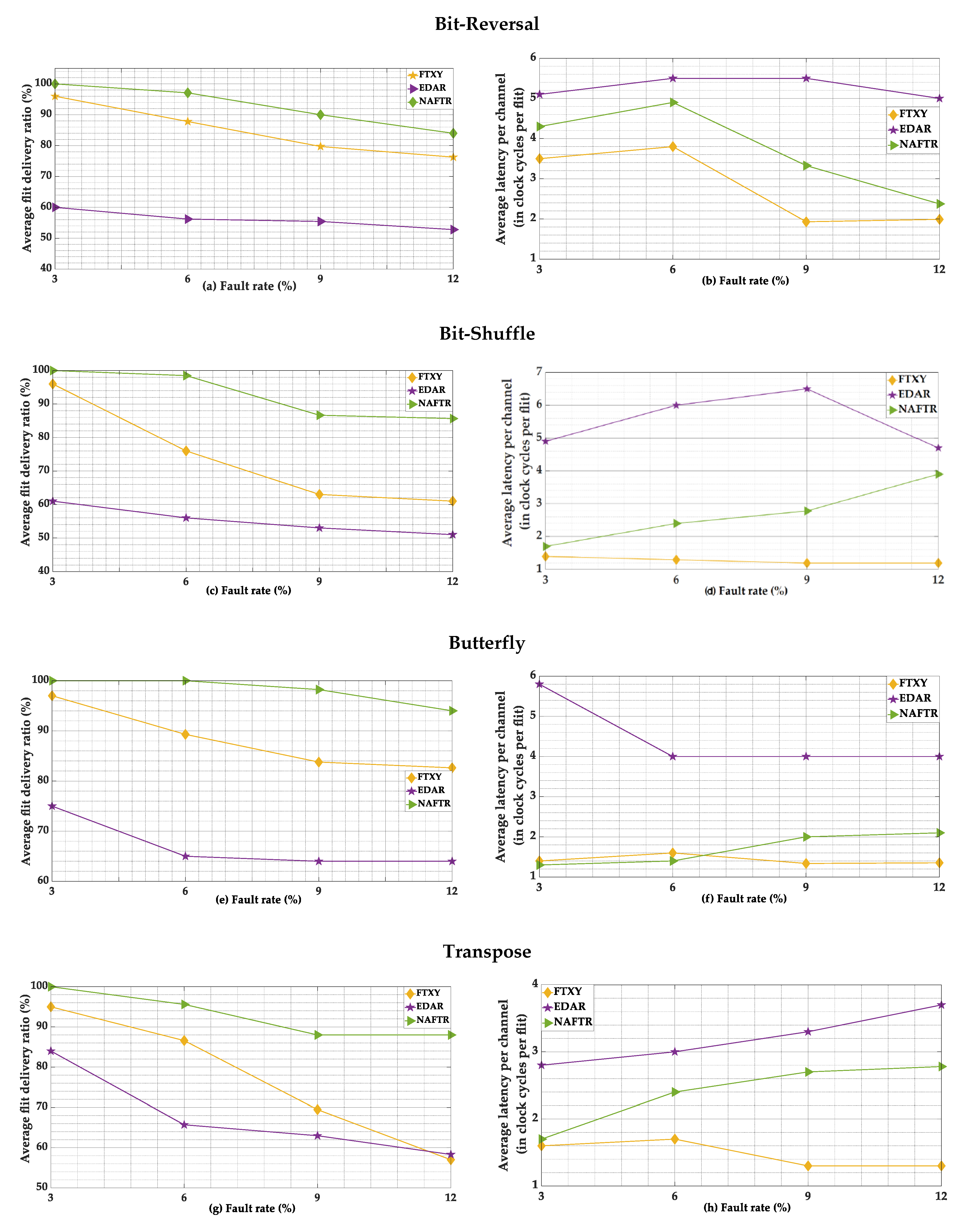
5. Experimental Results

The proposed routing algorithm NAFTR was compared with EDAR and fault-tolerant XY (FTXY) under various traffic patterns, such as bit-reversal, bit-shuffle, butterfly, and transpose, with a variable packet injection rate (PIR) and a variable fault rate. Table 3 outlines the details about the simulator and its essential parameters. We have extended the Nirgam simulator [41] and embedded the NAFTR and EDAR algorithms. The performance assessment between the algorithms was completed on a mesh (2D) topology with numerous traffic patterns. To provide a reasonable examination of the algorithms, the fault rates of 3%, 6%, 9%, and 12% were applied arbitrarily.
Figure 7 shows the latency vs. average flit delivery ratio comparison of the routing algorithms examined, which was done in a fault-free network scenario at different packet injection rates. The latency increased as the data rate increased in all traffic patterns. In bit-reversal, bit-shuffle, and butterfly traffic patterns, the traffic was seriously imbalanced. As the data rate increased, it resulted in the formation of congested regions in the network. At higher data rates, FTXY had the highest latency because of its inability to avoid congested regions and congested ports in the network. At lower data rates, NAFTR had a latency equal to or higher than FTXY because of its adaptive nature. As the data rate increased, NAFTR experienced lower latency than FTXY because of its key feature of avoiding congested regions. NAFTR also balanced the traffic among outports with a similar number of hops to the destination. Moreover, FTXY and NAFTR maintained a higher flit delivery ratio than EDAR because of their ability to handle livelocks in the network. Although EDAR had a lower average latency than FTXY and NAFTR, it achieved a lower flit delivery ratio. Due to EDAR’s inability to select an alternate outport, the outport of a packet was occasionally the same as the inport of the packet, thus resulting in livelock in the network and consequently leading to a lower flit delivery ratio and non-monotonic behavior. Under the transpose traffic pattern in Figure 7d, NAFTR experienced slightly higher latency than FTXY because in the transpose traffic pattern, the traffic is not as severely imbalanced as in the case of bit-reversal, bit-shuffle, and butterfly patterns. Therefore, NAFTR followed longer paths to avoid rare busy and congested ports in the network, resulting in slightly higher average latency per channel at higher data rates.
Figure 8 shows the average latency per channel and the average flit delivery ratio comparison of FTXY, EDAR, and NAFTR at different fault rates under various synthetic traffic patterns. Figure 8a,b show that NAFTR achieved a higher average flit delivery ratio at higher fault rates because of its ability to select the next-lowest weight outport when the outport calculated was equal to the inport of a packet. NAFTR followed longer paths to avoid faults and congested regions in the network, which resulted in a slight increase in average latency per channel compared to FTXY. EDAR had the highest average latency per channel because of its inability to select an alternate outport when the calculated outport was the same as the inport of the packet, which resulted in livelock, consequently leading to a higher latency in the network. The comparison results under bit-shuffle, butterfly, and transpose traffic patterns in Figure 8c–h show that NAFTR outperformed FTXY and EDAR by offering a higher flit delivery ratio at higher fault rates.
Figure 9a shows the total average network power consumed by FTXY, EDAR, and NAFTR in the fault-free network scenarios. The results indicate that EDAR and NAFTR consumed more power than FTXY as they required additional circuits to avoid busy and congested ports/regions in the network. On average, EDAR consumed 130% more power than FTXY, while NAFTR consumed only 33% more power than FTXY. Moreover, NAFTR consumed 41% less power than EDAR on average because of its ability to avoid congested regions in the network (passing through congested regions requires additional power to hold the flits in intermediate virtual channels until the route is clear and the packet can be passed to the next hop). Figure 9b shows the total network average power consumed by EDAR, FTXY, and NAFTR in faulty network scenarios. The results show that EDAR and NAFTR consumed 76% and 67% more power than FTXY, respectively, as they consumed additional power to avoid congested and busy channels. However, NAFTR consumed 5% less total network average power than EDAR, while it offered a higher flit delivery ratio than FTXY and EDAR, as shown in Figure 8.

Hardware Requirement Analysis

The modified EMBRACE router architecture requires one OR and one AND gate per outport to signal neighbor nodes about congested regions to make them avoid congested regions in the network. For the 2D mesh topology, a modified Embrace router architecture requires four OR and four AND gates per router to avoid congested regions in the network. A four-input AND gate requires eight complementary metal-oxide-semiconductor (CMOS) transistors, while a two-input OR gate requires six CMOS transistors; therefore, a total of 56 CMOS transistors are required per router. For a 5 × 5 network, the total number of increased CMOS transistors would be 1400. This is not very high given that nowadays, millions of transistors are embedded in a single chip.

6. Conclusions

In this article, we propose a routing algorithm (NAFTR) for NoC interconnections. The proposed algorithm introduces a three-fold optimization of EDAR. First, NAFTR introduces load balancing of the traffic between routes that are an equal distance from the destination. To perform this load balancing, when all outports lead to routes having an equal hop count to a destination, NAFTR randomly selects an outport for packet forwarding. Second, NAFTR can also avoid livelocks by choosing an alternate route. When there is a possibility of a livelock, NAFTR calculates the outport with the next-lowest weight and forwards the packet to that alternate outport. Lastly, NAFTR is also able to avoid congested regions in the network. NAFTR achieves this through the use of one AND and one OR gate per port at the router. NAFTR was extensively compared with EDAR and FTXY under numerous synthetic traffic patterns and variable fault rates. The simulation results illustrated that NAFTR reduced the latency because of its ability to avoid congested regions and NAFTR also achieved a higher flit delivery ratio in a fault-free network due to its ability to avoid livelocks. Moreover, NAFTR also achieved a higher flit delivery ratio of up to 18% in the presence of multiple faults, while consuming less power than EDAR. In the future, we plan to extend NAFTR to work for other network topologies, such as 3D, honeycomb, and torus topologies. We plan to make NAFTR a routing algorithm that can be configured on the fly for most of the widely used topologies in NoCs. NAFTR can also be extended to work with wireless NoCs, where congestion and business can be a critical factor for wireless routers. Additionally, NAFTR can also be implemented on real hardware to further emphasize its performance gains.

Author Contributions

Z.N. conceived and designed the algorithm. Z.N. and S.A. performed the experiments and analyzed the results. Z.N. wrote the paper. M.K.A., R.A., and S.A. proofread the manuscript. S.W.K. supervised and finalized the manuscript for submission. All authors have read and agreed to the published version of the manuscript.

Funding

This work was supported by the 2020 Yeungnam University Research Grant and by the Brain Korea 21 Plus Program (No. 22A20130012814) funded by the National Research Foundation of Korea (NRF).

Conflicts of Interest

The authors declare no conflict of interest.

References

  1. Hassan, A.S.; Morgan, A.A.; El-Kharashi, M.W. An Enhanced Network-on-chip Simulation for Cluster-based Routing. Procedia Comput. Sci. 2016, 94, 410–417. [Google Scholar] [CrossRef]
  2. Fathi, M.; Ebrahimi, S.; Pedram, H. A fault-tolerant routing algorithm in 3D topology manycore processors. In Proceedings of the 2015 2nd International Conference on Knowledge-Based Engineering and Innovation (KBEI), Tehran, Iran, 5–6 November 2015; pp. 217–222. [Google Scholar]
  3. Yang, P.; Wang, Q. Heterogeneous Honeycomb-like NoC Topology and Routing based on Communication Division. Int. J. Futur. Gener. Commun. Netw. 2015, 8, 19–26. [Google Scholar] [CrossRef]
  4. Anuradha, K.S.; Mahendra, A.G. Review of Odd-Even Routing Algorithm for 2D Mesh Topology of Network-on-Chip Architecture for Bursty Traffic. IJCA Spec. Issue Recent Trends Eng. Technol. 2013, RETRET, 9–12. [Google Scholar]
  5. Gulzari, U.A.; Anjum, S.; Aghaa, S.; Khan, S.; Torres, F.S. Efficient and scalable cross-by-pass-mesh topology for networks-on-chip. IET Comput. Digit. Tech. 2017, 11, 140–148. [Google Scholar] [CrossRef]
  6. Gulzari, U.A.; Sajid, M.; Anjum, S.; Agha, S.; Torres, F.S. A New Cross-By-Pass-Torus Architecture Based on CBP-Mesh and Torus Interconnection for On-Chip Communication. PLoS ONE 2016, 11, 0167590. [Google Scholar] [CrossRef] [Green Version]
  7. Glass, C.J.; Ni, L.M. The Turn Model for Adaptive Routing. In Proceedings of the 19th Annual International Symposium on Computer Architecture, Queensland, Australia, 19–21 May 1992; pp. 278–287. [Google Scholar]
  8. Jiang, S.; Jiang, S.; Liu, P.; Liu, Y.; Cheng, H. Network on Chip-based Fault-Tolerant Routing Algorithm and Its Implementation. Trans. Comput. Sci. Technol. 2013, 2, 55–61. [Google Scholar]
  9. Chand, M.S.; Naveen, C.; Dharm, J. An Efficient Routing Implementation for Irregular Networks. Glob. J. Comput. Sci. Technol. 2014, 14, 65284796. [Google Scholar]
  10. Liu, J.; Harkin, J.; Li, Y.; Maguire, L. Low-cost fault-tolerant routing algorithm for Networks-on-Chip. Microprocess. Microsyst. 2015, 39, 358–372. [Google Scholar] [CrossRef]
  11. Du, G.; He, J.; Song, Y.; Zhang, D.; Wu, H. Comparison of NoC routing algorithms based on packet-circuit switching. In Proceedings of the 2013 IEEE Third International Conference on Information Science and Technology (ICIST), Yangzhou, China, 23–25 March 2013; pp. 707–710. [Google Scholar]
  12. Chiu, G.-M. The Odd-Even Turn Model for Adaptive Routing. IEEE Trans. Parallel Distrib. Syst. 2000, 11, 729–738. [Google Scholar] [CrossRef] [Green Version]
  13. Boura, Y.M.; Das, C.R. Efficient fully adaptive wormhole routing in n-dimensional meshes. In Proceedings of the 14th International Conference on Distributed Computing Systems, Poznan, Poland, 21–24 June 1994; pp. 589–596. [Google Scholar]
  14. Chien, A.A.; Jae, H.K. Planar-Adaptive Routing: Low-cost Adaptive Networks for Multiprocessors. In Proceedings of the 19th Annual International Symposium on Computer Architecture, Queensland, Australia, 19–21 May 1992; pp. 268–277. [Google Scholar]
  15. Reza, A.; Ali, A.E.; Farshad, S. An efficient fault-tolerant routing algorithm in NoCs to tolerate permanent faults. J. Supercomput. 2016. [Google Scholar] [CrossRef]
  16. Glass, C.J.; Ni, L.M. Fault-tolerant wormhole routing in meshes. In Proceedings of the FTCS-23 The Twenty-Third International Symposium on Fault-Tolerant Computing, Toulouse, France, 22–24 June 1993; pp. 240–249. [Google Scholar]
  17. Wu, J. A Fault-Tolerant and Deadlock-Free Routing Protocol in 2D Meshes Based on Odd-Even Turn Model. IEEE Trans. Comput. 2003, 52, 1154–1169. [Google Scholar]
  18. Chalasani, S.; Boppana, R.V. Fault-Tolerant Wormhole Routing Algorithms for Mesh Networks. IEEE Trans. Comput. 1995, 44, 848–864. [Google Scholar]
  19. Chiu, K.-H.C.A.G.-M. Fault-Tolerant Routing Algorithm for Meshes Without Using Virtual Channels. J. Inf. Sci. Eng. 1998, 14, 765–783. [Google Scholar]
  20. Su, C.-C.; Shin, K.G. Adaptive Fault-Tolerant Deadlock-Free Routing in Meshes and Hypercubes. IEEE Trans. Comput. 1996, 45, 666–683. [Google Scholar]
  21. Park, D.; Nicopoulos, C.; Kim, J.; Vijaykrishnan, N.; Das, C.R. Exploring Fault-Tolerant Network-on-Chip Architectures. In Proceedings of the International Conference on Dependable Systems and Networks, Philadelphia, PA, USA, 25–28 June 2006; pp. 93–104. [Google Scholar]
  22. Schonwald, T.; Zimmermann, J.; Bringmann, O.; Rosenstiel, W. Fully Adaptive Fault-Tolerant Routing Algorithm for Network-on-Chip Architectures. In Proceedings of the 10th Euromicro Conference on Digital System Design Architectures, Methods and Tools, Lubeck, Germany, 29–31 August 2007; pp. 527–534. [Google Scholar]
  23. Singh, S.K.; Mondal, A.J.; Majumder, A. Generation and Performance Evaluation of Reconfigurable Fault-Tolerant Routing Algorithm for 2D-Mesh NoC. Procedia Comput. Sci. 2015, 57, 232–240. [Google Scholar] [CrossRef] [Green Version]
  24. Tse, S.S.H.; Zhou, J.; Lau, F.C.M. Fault-tolerant Routing for Irregular Faulty Patterns in 2D-Mesh Without Virtual Channel. In Proceedings of the 2012 12th International Symposium on Pervasive Systems, Algorithms and Networks, San Marcos, TX, USA, 13–15 December 2012; pp. 96–103. [Google Scholar]
  25. Bishnoi, R. Hybrid fault-tolerant routing algorithm in NoC. Perspect. Sci. 2016, 8, 586–588. [Google Scholar] [CrossRef] [Green Version]
  26. Yang, P.; Wang, Q.; Li, W.; Yu, Z.; Ye, H. A Fault Tolerance NoC Topology and Adaptive Routing Algorithm. In Proceedings of the 2016 13th International Conference on Embedded Software and Systems (ICESS), Chengdu, China, 13–14 August 2016; pp. 42–47. [Google Scholar]
  27. Moriam, S.; Fettweis, G.P. Reliability assessment of fault-tolerant routing algorithms in networks-on-chip: an analytic approach. In Proceedings of the Conference on Design, Automation & Test in Europe, Lausanne, Switzerland, 27–31 March 2017; pp. 61–66. [Google Scholar]
  28. Melo, D.R.; Zeferino, C.A.; Dilillo, L.; Bezerra, E.A. Maximizing the Inner Resilience of a Network-on-Chip through Router Controllers Design. Sensors 2019, 19, 5416. [Google Scholar] [CrossRef]
  29. Zhang, Z.; Serwe, W.; Wu, J.; Yoneda, T.; Zheng, H.; Myers, C. An improved fault-tolerant routing algorithm for a Network-on-Chip derived with formal analysis. Sci. Comput. Program. 2016, 118, 61–66. [Google Scholar] [CrossRef]
  30. Xiang, D.; Pan, Q. Low-power and high-performance adaptive routing in on-chip networks. CCF Trans. HPC 2019, 1, 92–110. [Google Scholar] [CrossRef] [Green Version]
  31. Deb, D.; Jose, J.; Das, S.; KKapoor, H. Cost effective routing techniques in 2D mesh NoC using on-chip transmission lines. J. Parallel Distrib. Comput. 2019, 123, 118–129. [Google Scholar] [CrossRef]
  32. Song, Y.; Lin, B. Uniform Minimal First: Latency Reduction in Throughput-Optimal Oblivious Routing for Mesh-Based Networks-on-Chip. IEEE Embed. Syst. Lett. 2019, 11, 81–84. [Google Scholar] [CrossRef]
  33. Lin, L.; Sun, Y.; Zhu, Z.; Yang, Y. A congestion-aware OE router employing fair arbitration for network-on-chip. J. Semicond. 2018, 39, 125006. [Google Scholar] [CrossRef]
  34. Kang, J.; Cunlu, L.; Dezun, D.; Binzhang, F. HARE: History-Aware Adaptive Routing Algorithm for Endpoint congestion in Networks-on-Chip. Int. J. Parallel Program. 2018, 47, 433–450. [Google Scholar]
  35. Carrillo, S.; Harkin, J.; McDaid, L.; Pande, S.; Cawley, S.; McGinley, B.; Morgan, F. Advancing interconnect density for spiking neural network hardware implementations using traffic-aware adaptive network-on-chip routers. Neural Networks 2012, 33, 42–57. [Google Scholar] [CrossRef] [PubMed]
  36. Liu, J.; Harkin, J.; Li, Y.; Maguire, L. Online traffic-aware fault detection for networks-on-chip. J. Parallel Distrib. Comput. 2014, 74, 1984–1993. [Google Scholar] [CrossRef]
  37. Pande, S.; Morgan, F.; Smit, G.; Bruintjes, T.; Rutgers, J.; McGinley, B.; Cawley, S.; Harkin, J.; McDaid, L. Fixed latency on-chip interconnect for hardware spiking neural network architectures. Parallel Comput. 2013, 39, 357–371. [Google Scholar] [CrossRef] [Green Version]
  38. Carrillo, S.; Harkin, J.; McDaid, L.J.; Pande, S.; Cawley, S.; McGinley, B.; Morgan, F. Hierarchical Network-on-Chip and Traffic Compression for Spiking Neural Network Implementations. In Proceedings of the 2012 IEEE/ACM Sixth International Symposium on Networks-on-Chip, Lyngby, Denmark, 9–11 May 2012; pp. 83–90. [Google Scholar]
  39. Jerger, N.E. On-Chip Networks; Morgan & Claypool: San Rafael, CA, USA, 2009; Volume 4. [Google Scholar]
  40. Alhussien, A.; Wang, C.; Bagherzadeh, N. Design and evaluation of a high throughput robust router for network-on-chip. IET Comput. Digit. Tech. 2012, 6, 173–179. [Google Scholar] [CrossRef]
  41. School of Electronics and Computer Science, University of Southampton. Available online: http://nirgam.ecs.soton.ac.uk/ (accessed on 10 February 2020).
Figure 1. Restricted turns in different deterministic and partially adaptive routing algorithms.
Electronics 09 01076 g001
Figure 2. (a) EDAR behavior in the presence of a congested region in the network. (b) EDAR behavior when selecting between outports with the same number of hops to the destination.
Electronics 09 01076 g002
Figure 3. Generic 2D-mesh NoC topology.
Electronics 09 01076 g003
Figure 4. Network adaptive fault-tolerant routing (NAFTR) region distribution.
Electronics 09 01076 g004
Figure 5. Modified EMBRACE router architecture. FIFO: First in, first out; MM: Monitor module.
Electronics 09 01076 g005
Figure 6. Modified EMBRACE behavior for avoiding congested regions.
Electronics 09 01076 g006
Figure 7. Average latency vs. average flit delivery ratio comparison under synthetic traffic patterns at different pack injection rates in a fault-free scenario.
Electronics 09 01076 g007
Figure 8. Overall average latency vs. flit delivery ratio comparison at different fault induction rates under synthetic traffic patterns.
Electronics 09 01076 g008
Figure 9. Total network average power consumed under faultless and faulty network scenarios.
Electronics 09 01076 g009
Table 1. Comparison of the state-of-the-art for routing in a network-on-a-chip (NoC).
Ref.Primary Focus of the Study is to ProposeSupported Network TopologyAnalysis Performed onVirtual Channel Utilization to Avoid FaultsFault ToleranceCongestion AwarenessBusiness AwarenessProposed Algorithm Compared with
Glass et al. [16]Negative-first-based adaptive fault-tolerant routing 2D meshIn-house built simulator×××Negative first
Jie Wu [17]Adaptive fault-tolerant routing 2D mesh×××-
Boppana et al. [18]Adaptive fault-tolerant routing2D mesh and torus××e-cube
Chen et al. [19]Adaptive fault-tolerant routing2D mesh×××Boura’s algorithm
Su et al. [20]Adaptive fault-tolerant routing2D mesh and hypercube××e-cube
Park et al. [21]Adaptive fault-tolerant routing2D mesh××-
Schonwald et al. [22]Adaptive fault-tolerant routing2D mesh and torus×××XY
Singh et al. [23]Adaptive fault-tolerant routing2D mesh××XY, west first, north last, negative first
Tse et al. [24]Adaptive fault-tolerant routing2D mesh-×××-
Bishnoi [25]Adaptive fault-tolerant routing2D mesh-××-
Yang et al. [26]Adaptive fault-tolerant routingHoneycombNirgam Simulator××Dimensional order routing
Moriam et al. [27]Analytical model to assess fault-tolerant routing algorithms2D mesh and hexagonalIn-house built simulator-----
Douglas et al. [28]Router controller design2D mesh-××-
Zhang et al. [29]Fault-tolerant routing2D meshIn-house built simulator-××-
Xiang et al. [30]Fully adaptive routing2D mesh××××DyXY, DP, SU, EVC
Deb et al. [31]Routing technique using on-chip transmission lines2D meshBooksim simulator×××-
Song et al. [32]Latency reduction in oblivious routing2D meshPopNet simulator××××Valiant, dimension order routing
Liu et al. [33]Congestion-aware odd-even (OE) router employing fair arbitration2D meshNoxim simulator×××OE, CAOE-random
Jin et al. [34]History-aware adaptive Routing for end-point congestion2D meshBooksim simulator×××Footprint, Dimensional order routing
Liu et al. [10]Low-cost fault-tolerant routing2D meshNoxim simulator×DyAD, OE, XY, Negative first, FoN, Cost, FTDR, FTDR-H, LAFT, HLAFT,
This workFault-tolerant routing for throughput and latency-critical NoC architectures2D meshNirgam simulator×EDAR, FTXY
e-cube is a static routing method that employs XY-routing algorithm for hypercube networks., express virtual channel (EVC), dynamic XY (DyXY), VCT-switched Duato’s protocol (DP), safe unsafe(SU), congestion aware odd-even (CAOE), dynamic adaptive (DyAD), look ahead fault-tolerant(LAFT), hybrid look ahead fault-tolerant (HLAFT), fault-tolerant deflection routing (FTDR), fault on neighbor(FoN), hierarchical FTDR (FTDR-H).
Table 2. Key Notations.
VariableDescription
C u r r e n t   I D ID of the current node
D e s t i n a t i o n   I D ID of the destination node
X c u r x coordinate of the current node
Y c u r y coordinate of the current node
X d e s t x coordinate of the destination node
Y d e s t y coordinate of the destination node
n u m c o l s Number of columns in the network
I n p o r t Inport of incoming flit
O u t p o r t Selected outgoing port for a flit
S b [ N / E / S / W ] Busy status of neighboring channels
S c [ N / E / S / W ] Congestion status of neighboring channels
S f [ N / E / S / W ] Fault status of neighboring channels
W p [ N / E / S / W ] Direction priority of each outport, which depends on the location of the destination node
W b [ N / E / S / W ] Weight for busy neighboring channels either have a value of 0 or 2
W c [ N / E / S / W ] Weight for congested neighboring channels either have a value of 0 or 3
W f [ N / E / S / W ] Weight for faulty neighboring channels either have a value of 0 or 10
W i [ N / E / S / W ] Total weight of each outport, which is calculated by adding W b , W c ,   W p , and W f
Table 3. Simulation parameters.
NameDescription
SimulatorNirgam 2.1
Routing algorithmsEDAR, FTXY, NAFTR
Topology2D mesh
Traffic patternBit-shuffle, bit-reversal, butterfly, transpose
Size of the network5 × 5
Warm-up time5 cycles
Simulation time5000 cycles
Fault percentage3%, 6%, 9%, 12%

