In this section, we apply the theory developed in [
9] to several classes of problems that could not be managed with the previous theories [
5,
6,
7,
8]. The conditions are established on the constitutive parameters of such problems, under which the well posedness and finite element approximability can be guaranteed. In particular, we apply the theory and obtain solutions for three examples of bianisotropic media, which are found in the open literature. The first one is that introduced in [
1] where the authors considered plasmonic gratings, which are represented by an equivalent bianisotropic media. In this case, we study the scattering from a slab of the equivalent medium, which is placed in empty space, in accordance with the setup considered by the authors [
1]. Next, the media introduced in [
10,
11] are analyzed. The authors there considered the scattering from the bianisotropic obstacles placed inside hollow waveguides. Although we stick to the original configurations proposed by the authors, our tools can be used to analyze other problems involving these media.
Under the conditions that guarantee that hypotheses H1–H7 are satisfied, the numerical solutions of these problems are computed. They can be used as reference solutions for other approaches and simulators because, on the one hand, for each problem, our theory guarantees the convergence of the sequence of approximations, and on the other hand, we verify that the outcome we present is close to the limit of the sequence by a stability analysis of the numerical solutions.
3.1. Scattering from Plasmonic Gratings Behaving as Bianisotropic Metamaterials
In [
1], the authors considered a plasmonic grating that exhibits bianisotropy at visible wavelengths. The bianisotropic media considered there are of the form:
with:
Here,
,
, and
are complex valued functions and are set to be equal to a unique value
. Moreover,
,
, and
are each set equal to one, and
is taken to be real valued. The region occupied by the scatterer may be denoted as
. The above form can be converted into the alternative form of constitutive relations [
13] involving the
P,
Q,
L, and
M matrices defined in Equation (
1), and the final result is shown in the following equations:
Here,
is the three by three identity matrix. The complementary region
is occupied by the empty space, which is characterized by
,
,
. This problem cannot be managed by the previous theories and, in particular, by the theory in [
5], which relied on strong hypothesis about losses.
The bianisotropic medium is lossy with the imaginary part
, whereas
is assumed real here to avoid some longer calculations. Now, Lemma 1 can be applied to verify hypothesis H5. Inside
,
P can be decomposed as
with:
and
. Hence, we have
, the lossy region where
is uniformly positive definite and the complementary region with the free space where
is uniformly positive definite. This means that the conditions of Lemma 1 are satisfied, and as a result, H5 is valid.
From the definitions (see Equations (
11), (
12), and (
15)),
,
, and
. To find the minimum of the two expressions in Equation (
14), we note that, in the valid range, the value of the first expression decreases monotonically with
, whereas that of the second expression increases with it. The highest estimate for
is obtained when the two expressions have the same value. The value of
at which this happens can be evaluated by equating the two expressions and finding the positive root of the resulting quadratic equation. This value of
, denoted as
, is given by:
Thus, we may simply write:
As mentioned in [
9], this does not mean that a better value of
cannot be found. For example, if
, then
is uniformly positive definite in
, and we can find another candidate for
, namely
(see Equation (
31) of [
9]). In particular, when
,
is always going to give a value for
that is higher than that obtained from the lemma.
In the rest of the subsection, the discussion focuses on the cases with
, which gives a non-definite
in
. For this case,
, and we can directly use the value of
in Equation (
29). Since the material is assumed to be non-magnetic, the direct application of the definition gives
, and H6 is valid. Likewise, for the continuity constants
and
, we can choose the value
. Then, the inequality in H7 becomes
, which gives:
Since the right-hand side of Equation (
30) also depends on
due to the presence of
in the expression for
, we do not have a closed-form expression on the limit on
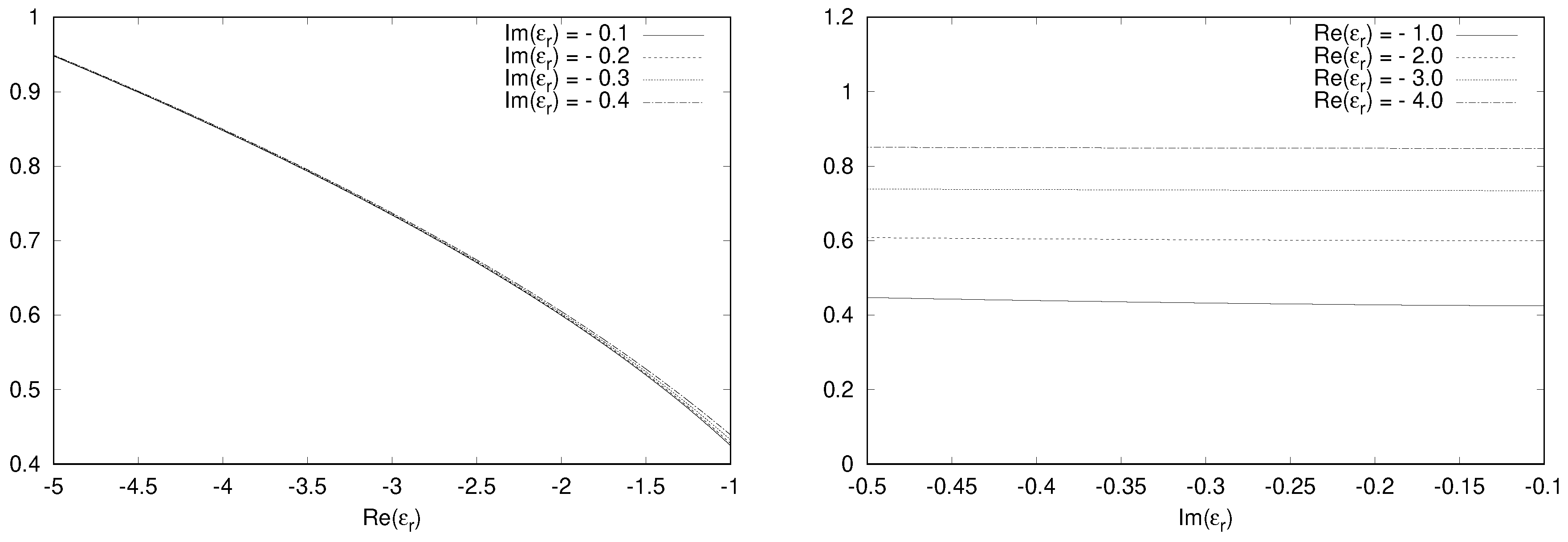
below which H7 is satisfied. However, a graphical analysis can be done for estimating such a limit on
, as shown in
Figure 1. The value of
is varied in the range
, whereas
assumes values in the range
. It can be observed that for a fixed value of
, the range of
over which H7 is valid steadily decreases as
increases. As for the dependence on
, the corresponding range increases when the medium becomes lossier due to higher
, as expected.
Since outside the region occupied by the bianisotropic media (
), we just have the empty space, H1 and H2 are trivially satisfied there. By Remark 1 of [
9], since H1, H3, and H4 need to hold only locally, now we have to just analyze them inside
occupied by the bianisotropic medium. We consider the alternative form of constitutive relations, which for the medium inside
becomes as in Equations (
31) to (
33), for examining the validity of H1, H3 and H4 [
13]:
The constants of interest can be evaluated directly from the definitions. The determinants of
and
are, respectively,
and
, which immediately give the values of
and
.
The inverses of the diagonal matrices
and
are just the diagonal matrices with the reciprocal entries. Applying Equations (40) and (41) of [
9] gives the values of
and
.
Using Equations (36) and (37) of [
9], we get
and
.
From Equations (
18) and (
19), we can easily evaluate
and
.
The hypotheses H1 and H3 are valid due to the existence of the above constants. Using these constants, the value of
can be calculated from Equation (
20). The critical value of
below which the condition in H4 is satisfied is plotted in
Figure 2, with respect to either
or
. The results show that the range of
for which H4 holds true increases with the increase in
, while it is practically independent of
.
Let us try to understand the implications of the theory by applying it to the numerical solution of a specific problem involving the medium of interest. We consider the region with the scatterer to be a cube filled with homogeneous bianisotropic media. The surrounding region is filled with empty space, and the overall domain of numerical investigation, , has a cubic shape as well and is concentric to . In the following, and are characterized by sides of length 2 m and 0.8 m, respectively. The axes are taken along the sides of the cubic domain , and the excitation is with a plane wave incident along the x axis, with the electric field polarized along the z axis, having a magnitude of 1 V/m and wavelength of 1 m.
Inside , the medium is characterized by , , and . This value is such that the hypotheses required for well posedness and finite element approximability are satisfied. In fact, for the considered, condition H4 is valid for , and condition H7 is valid for .
The solutions are obtained with a first order edge element based Galerkin finite element method. The boundary condition is enforced with Y equal to the admittance of a vacuum and with an inhomogeneous term , taking into account the incident field.
The domain is discretized uniformly using tetrahedral meshes. The meshing is done by first dividing the domain into small identical cubes, each of which is in turn divided into six tetrahedra. The parameter
h denotes the maximum diameter of all the elements of the mesh [
14] (p. 131), and in this case, it is simply given by the side of the small cubes times
. To study the stability of the solution, we consider different levels of refinement of meshes ranked in order of
h, ranging from “very coarse” to “very fine”. For example, the mesh denoted as very coarse is characterized by cubes of sides 200 nm, and the resulting mesh has 1331 nodes, 6000 tetrahedral elements, and 1200 boundary faces. A summary of the information related to the four different refinements of the meshes that were used is given in
Table 1.
The outcomes related to the stability of the results of the simulations are shown in
Figure 3 by plotting the magnitude of the z component of the electric field along a line parallel to the
y axis and passing through the center of gravity of the domain. The difference between successive refinements progressively decreases, and the fine and very fine meshes give stable solutions. The well posedness and convergence result that was predicted using the theory guarantee that our solutions are reliable.
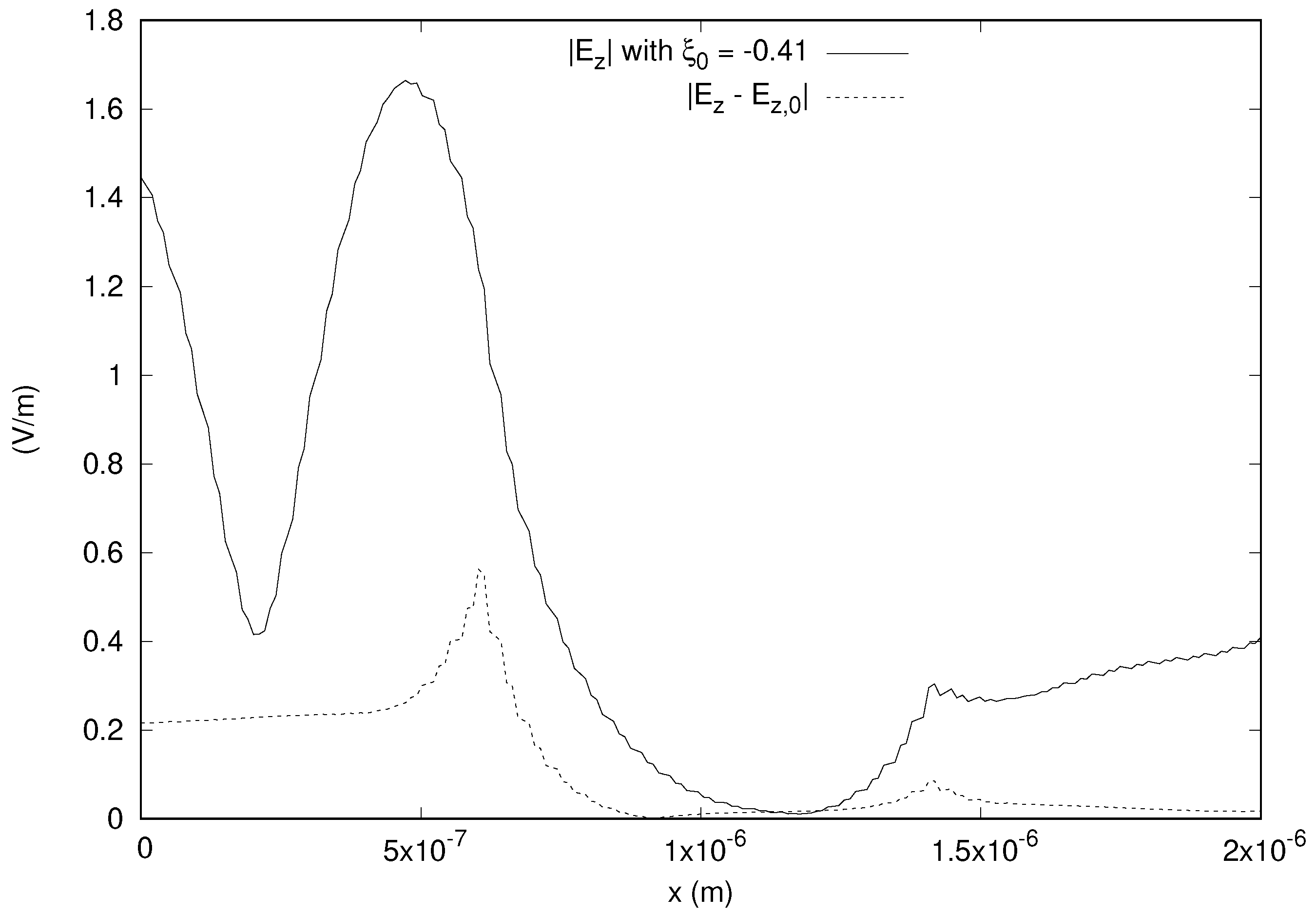
Figure 4 shows the significance of the bianisotropic effect on the z component of the electric field along a line parallel to the
x axis and passing through the center of gravity of the domain. Here,
denotes the solution obtained with
, and
is the solution when
, while the plot shows the magnitude of the difference
along with
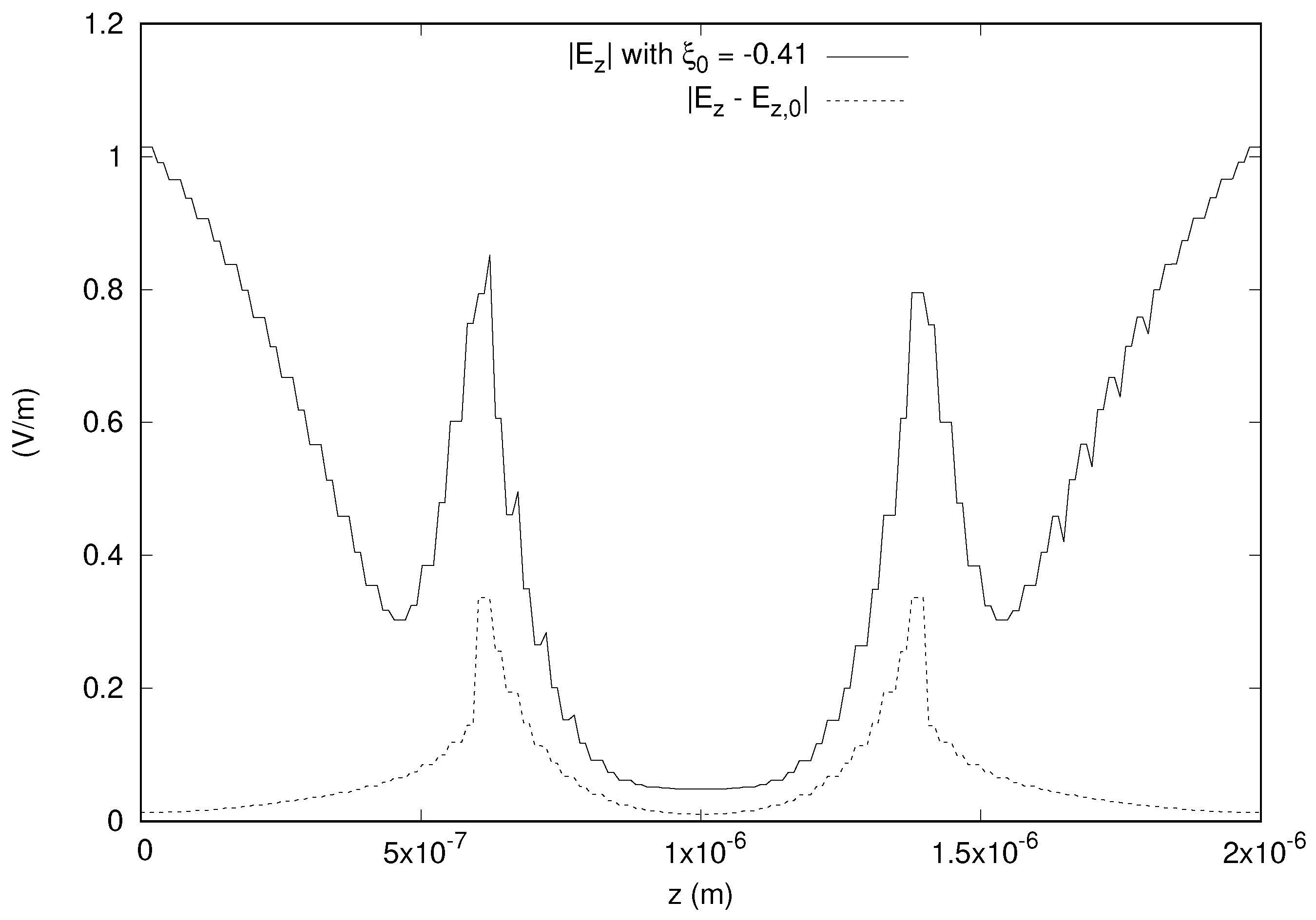
. The magnitude of the difference is as large as 50% of the incident field. Similarly, the results along a line parallel to the
z axis and passing through the center of gravity of the domain are shown in
Figure 5, and we get a difference of around 30% of the incident field.
These non-negligible effects imply that to get accurate results, it is necessary to consider the bianisotropy of the medium. Hence, the reliability of the finite element solution in the presence of bianisotropy is important for getting good results for these problems. The application of our theory gives the conditions under which we can guarantee such reliability. The solutions obtained can serve as references for other approaches.
3.2. Scattering from Chiral Obstacles in a Waveguide
In [
10], the authors considered a metallic waveguide, which was hollow except for an obstacle characterized by a chiral medium with the following constitutive relations.
Here,
,
, and
are strictly positive real quantities. Thus, from Equation (
1), we can easily identify
P,
Q,
L, and
M, which are given below:
In Section 6 of [
5], it was shown that this media could not be managed by the theory developed there, independently of the value of
and of any other material involved in the model of interest. However, we show that the generality of the recently developed theory in [
9] allows us to apply it to obtain the conditions for well posedness and finite element approximability for this kind of problem of practical interest.
Let us analyze the validity of the hypotheses by considering, as did the authors in [
10],
and
. We can make use of Lemma 1 of [
9] to check H5.
and is equal to
inside the material and simply
outside. Since
, a value of
can be found by using Equation (
13). In particular, H5 is satisfied for
. The hypothesis H6 is also trivially valid with
. By Equations (32) and (33) of [
9],
. Then, the inequality in hypothesis H7 becomes
, which implies:
This is not a small value considering the chiral effects reported in [
10]. As the region outside the obstacle is empty space, H2 is trivially satisfied, and by Remark 1 of [
9], we need to verify that the hypotheses H1, H3, and H4 hold true locally inside the region occupied by the bianisotropic medium. To do this, the suitable form of constitutive relations is in terms of
,
,
, and
, which are given by the following [
13]:
and
are multiples of the identity matrix with eigenvalues
and
, respectively. The determinants are just the cubes of the eigenvalues, and hence, according to Equations (34) and (35) of [
9], we get the values of
and
.
and
, by Equations (36) and (37) of [
9], are in this case simply twice the eigenvalue of the corresponding diagonal matrix:
The inverse of the matrices is also trivial, and Equations (40) and (41) of [
9] simply evaluate to the reciprocals of the eigenvalues of
and
, respectively giving
and
:
From Equations (
18) and (
19), we get:
Having shown that the hypotheses H1 and H3 are satisfied, we can use the above constants to calculate
to verify H4.
Figure 6 shows the dependence of
on
for various values of
. As the value of
increases, the hypothesis H4 remains valid for higher and higher values of
.
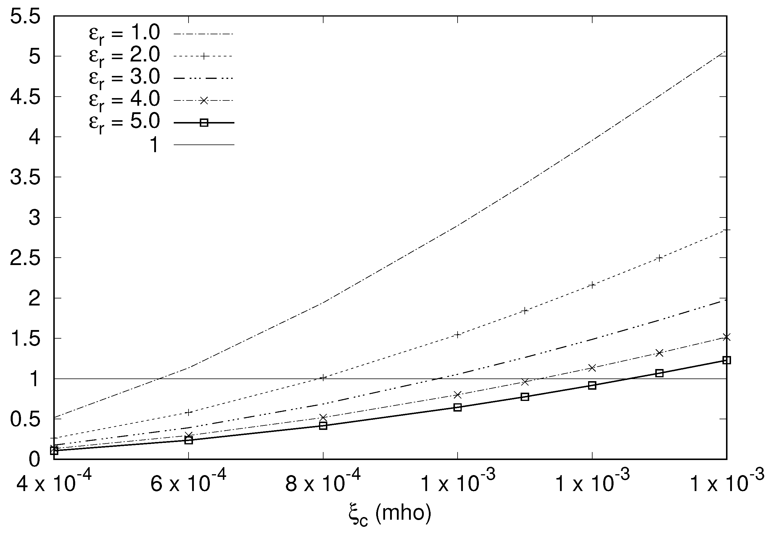
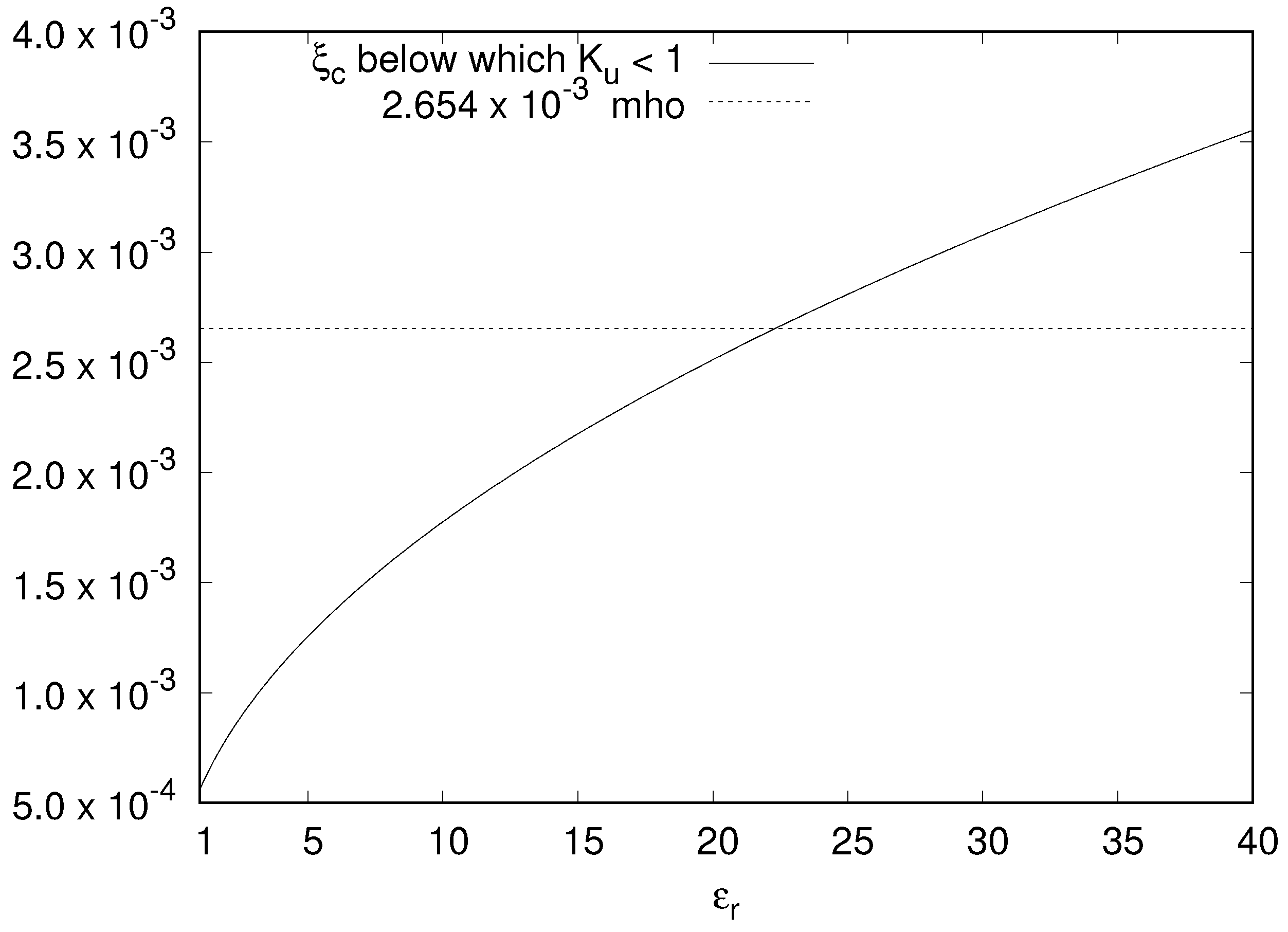
Figure 7 shows the plot of the critical value of
below which H4 is satisfied against
. The limit of
mho, arising from Equation (
45) required to satisfy H7, is also shown in the same figure. It is seen that for low values of
, the tighter condition arises from the need to satisfy H4. For example, the limiting value is
mho for
, increases with
, and is
mho for
. The curve crosses the
mho line at around
, and above that value, Equation (
45) imposes the stricter limit.
Now, we consider a specific numerical problem for which the solution is calculated using our finite element simulator. A rectangular waveguide with a discontinuity due to a block of bianisotropic medium is considered as shown in
Figure 8. In the simulation, the rectangular waveguide is characterized by
mm,
mm and has a length
mm. The obstacle is a parallelepiped with
mm,
mm and a length
mm. The origin of the axis is at the lower right corner of the near face of the waveguide shown in
Figure 8. The obstacle ranges from
mm to
mm along the
x axis, from
to
mm along the
y axis, and from
mm to
mm along the
z axis. The bianisotropic medium making up the obstacle is characterized by
and
mho. For this medium,
, and also, Equation (
45) is satisfied; hence, all the hypotheses required to guarantee the well posedness and convergence of finite element solutions hold true. The waveguide is excited with
mode having an amplitude of 1 V/m and a frequency of 9 GHz. The input port is on the x-y plane, and the output port is closed on a matched homogeneous admittance boundary condition for the
mode in the empty waveguide.
The details of the Galerkin finite element solver is the same as before. The tetrahedral meshes are obtained as discussed in the previous subsection by dividing the domain into small cubes, each of which is in turn subdivided into six tetrahedra. The stability of the solution is verified by checking the solutions for three different meshes, which are characterized by small cubes of sides
mm,
mm, and
mm, which are referred to as, respectively, “coarse”, “fine”, and “very fine” meshes. There are 10,824 nodes, 55,200 elements, and 6200 boundary faces in the coarse mesh, whereas the fine mesh has 79,947 nodes, 441,600 elements, and 24,800 boundary faces, and finally, the very fine mesh has 262,570 nodes, 1,490,400 elements, and 55,800 boundary faces. It was verified that the solutions obtained with these meshes are stable. For example,
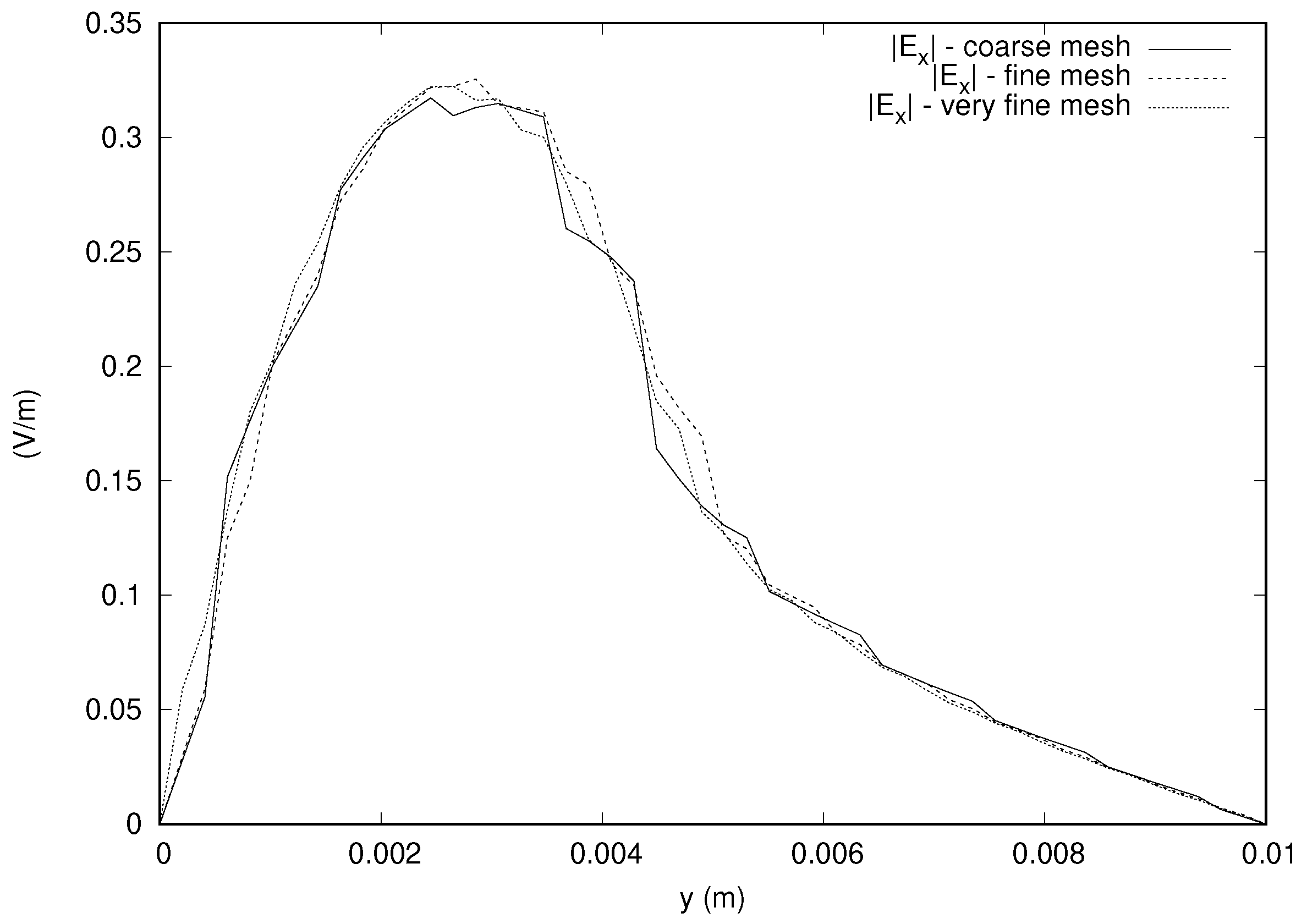
Figure 9 shows the magnitude of the x component of the electric field along a line parallel to the
y axis and passing through the center of gravity of the domain with the different meshes and illustrates the stability of the result. It is noted that the x component of the electric field along this line is zero for the achiral case (
), and there is a difference of more than 30% of the incident field, which is induced by the bianisotropy.
Figure 10 shows the result for the magnitude and phase of the x component of the electric field along the line parallel to the
x axis and passing through the center of gravity of the domain. We have a difference of 20% of the magnitude of the incident field for the x component of the electric field along this line. Similarly,
Figure 11 shows that the bianisotropic effect for the x component of the field along the line parallel to the
z axis and passing through the center of gravity of the domain causes a difference in the magnitude of the electric field of around 13% of the incident field.
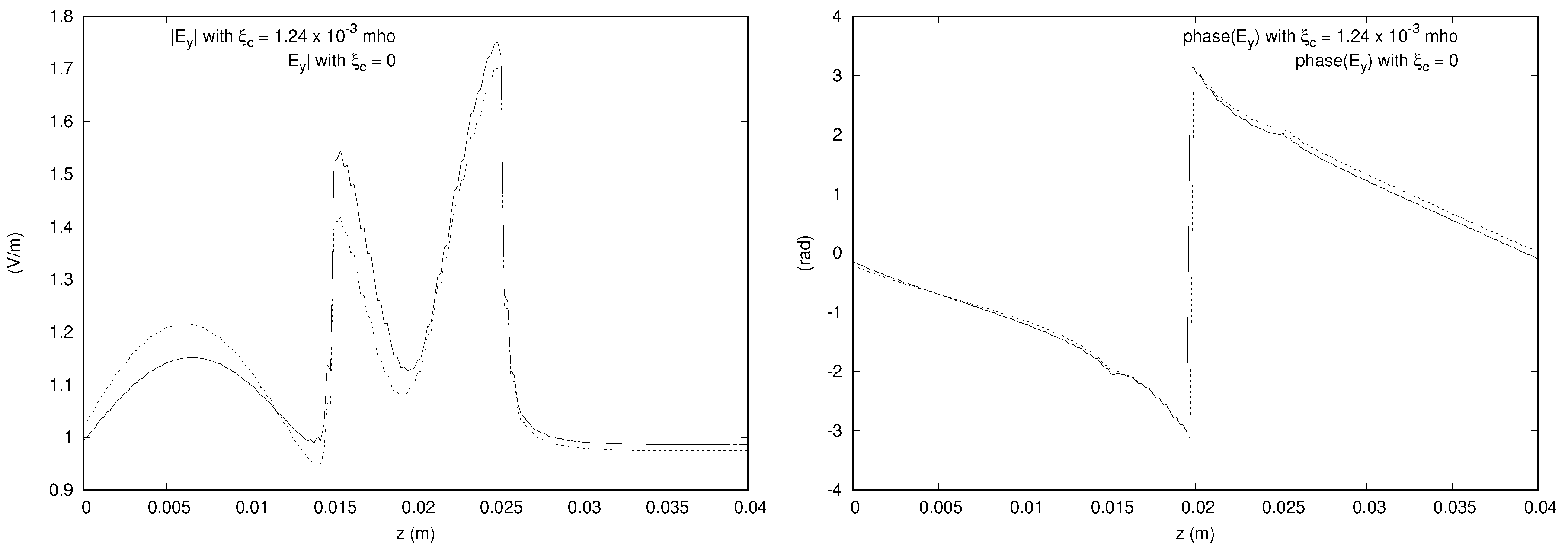
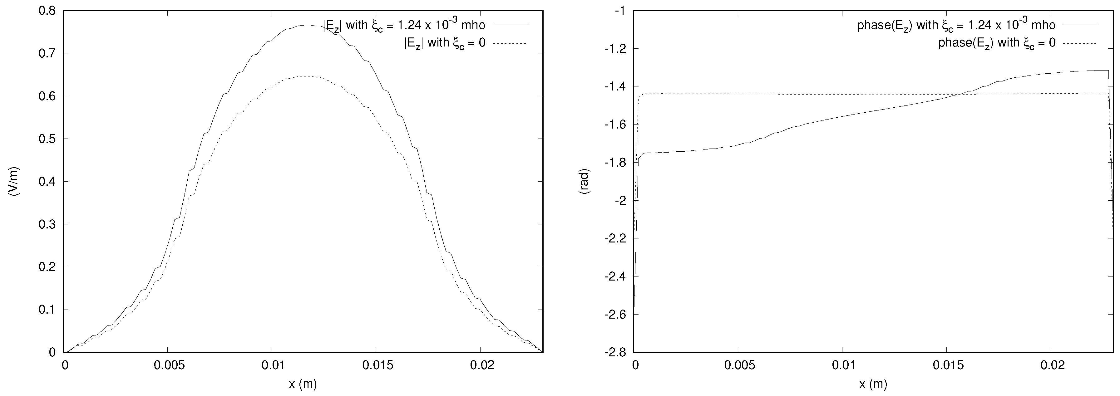
Figure 12 shows the y component of the electric field along a line parallel to the z axis and passing through the center of gravity of the domain. The bianisotropic effect is again not negligible and causes a difference of more than 10% of the incident field. A similar effect is present in the z component as can be seen in the plot along a line parallel to the
x axis and passing through the center of gravity of the domain, which is given in
Figure 13. We do not show the other figures to save space, but it is noted that the y component of electric field along the lines through the center of the domain and parallel to the
x and
y axes shows small differences in magnitude between the chiral and achiral cases, being less than five percent of the incident field. The z component on the other hand along the lines parallel to the
y and
z axes and passing through the center of the domain shows a difference of more than 15% of the incident field.
Together, these results provide a point of reference for other approaches of solving such problems, owing to the reliability of the results provided here, which is guaranteed by the recently developed theory. The previous theory [
5] was not able to manage these problems, and our results are therefore novel. In fact, to the best of our knowledge, there are no other approaches that are available to get reliable results for benchmarking. The significant bianisotropic effects demonstrated in the results show the practical importance of the theory for such media.
3.3. Reflection by a Short-Circuited Waveguide Half Filled with Bianisotropic Media
Another relevant bianisotropic medium was discussed in [
11], where the authors considered a short-circuited rectangular waveguide, half of which was empty and the other half filled with a lossless bianisotropic material characterized by:
where
A is the matrix given by:
and
is a positive real number.
The hypotheses H5 and H6 are trivially valid with
and
. Further,
whose eigenvalues are zero,
, and
. Therefore, by Equations (32) and (33) of [
9], we get
. The condition in hypothesis H7 then becomes
, which gives the following limit on
:
The hypothesis H2 holds true since the anisotropic part is just empty space. H1, H3, and H4 can be studied using the alternative form of constitutive relations, which is characterized by the following matrices [
13]:
The determinants of
and
can be readily calculated, and by using Equations (34) and (35) of [
9], we get
and
:
and
can be directly obtained from their definitions:
By simple application of the definition:
and by Equation (
41) of [
9],
evaluates to the reciprocal of the largest eigenvalue of the real matrix
, which is given by:
Equations (
18) and (
19) give:
The existence of the above constants verifies H1 and H3, and we can use them to calculate
to check H4. It can be verified that
is less than one when
mho, which is stricter than the limit obtained from Equation (
60).
Finally, let us give some numerical solutions for this problem, which can be used as references for other approaches. The cross-section of the waveguide is 2 cm along the
x axis and 1 cm along the
y axis, and the length of the waveguide is 2 cm, half of which is filled with the bianisotropic medium characterized by
mho (see
Figure 1 of [
11]). The origin is taken on the corner of the open face of the waveguide on the empty side.
mode is excited in the waveguide with a source of amplitude 1 V/m and a frequency of 12 GHz.
The first order edge element based Galerkin finite element method is used to obtain the solution. The meshing is carried out by dividing the domain into identical cubes, each of which is then subdivided into six tetrahedra. The stability of the result is ensured by evaluating the solutions on three meshes, termed as “coarse”, “fine”, and “very fine”, characterized, respectively, by cubes of sides 1 mm,
mm, and
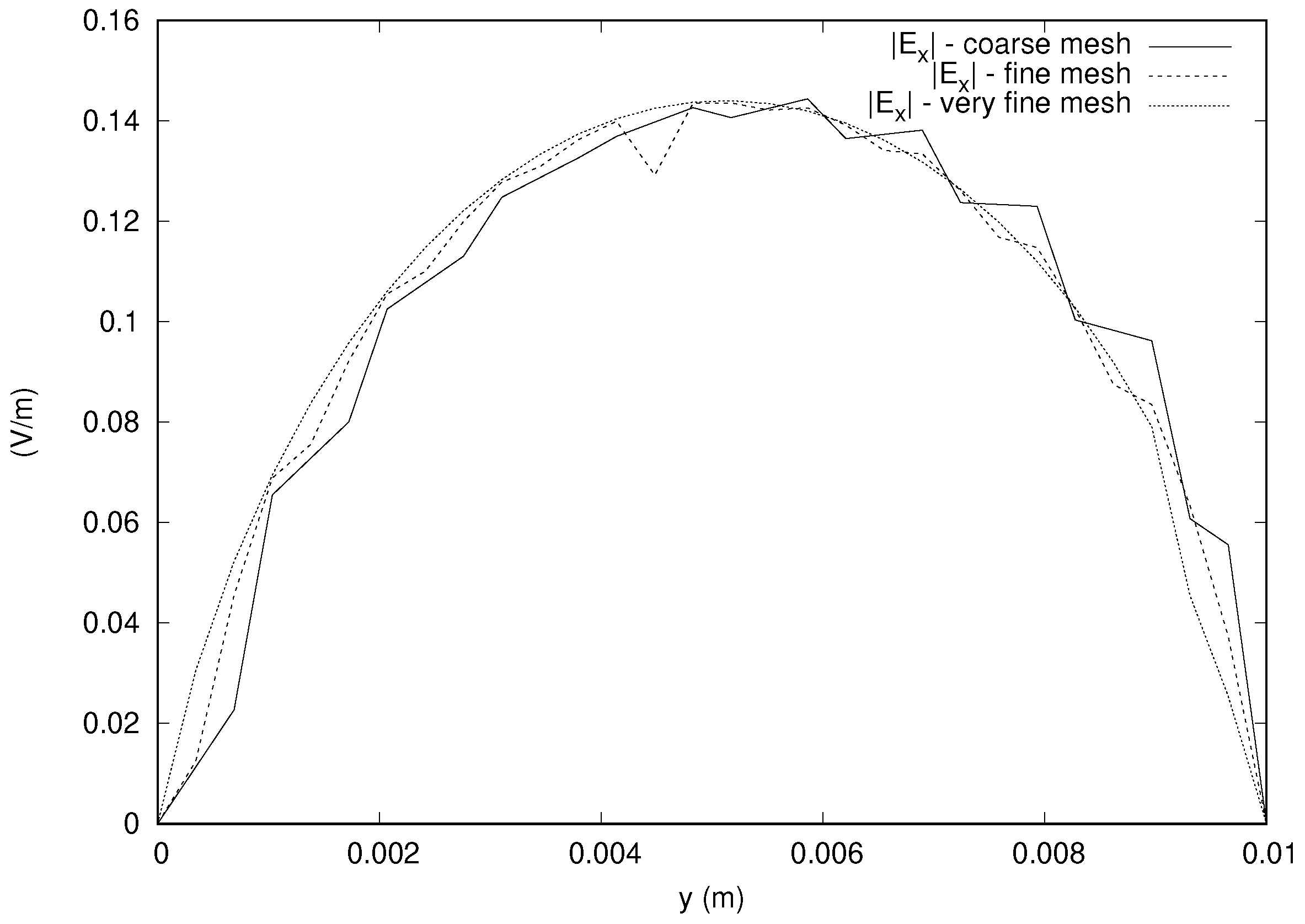
mm. The coarse mesh has 4852 nodes, 24,000 elements, and 3200 boundary faces. The fine mesh is composed of 35,301 nodes, 192,000 elements, and 12,800 boundary faces. The very fine mesh has 115,351 nodes, 648,000 elements, and 28,800 boundary faces. The results obtained with these meshes are stable. For example,
Figure 14 shows the stability of the results obtained with the three meshes for the x component of the electric field along a line parallel to the
y axis and passing through the center of gravity of the domain.
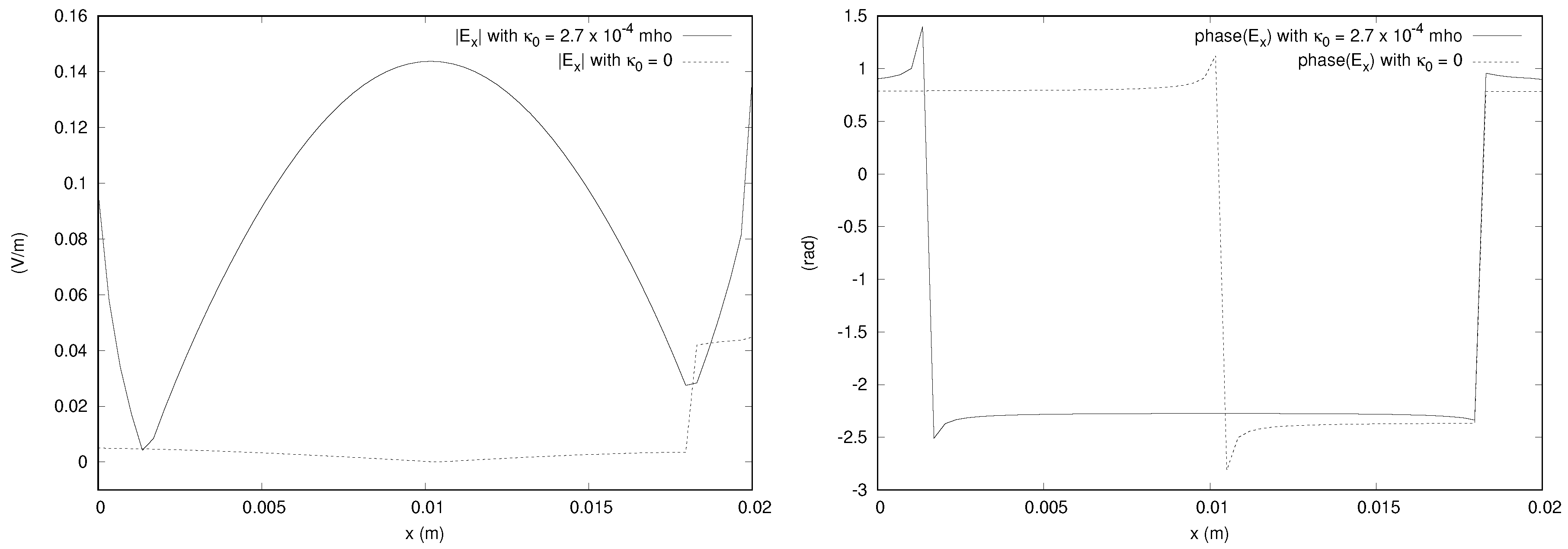
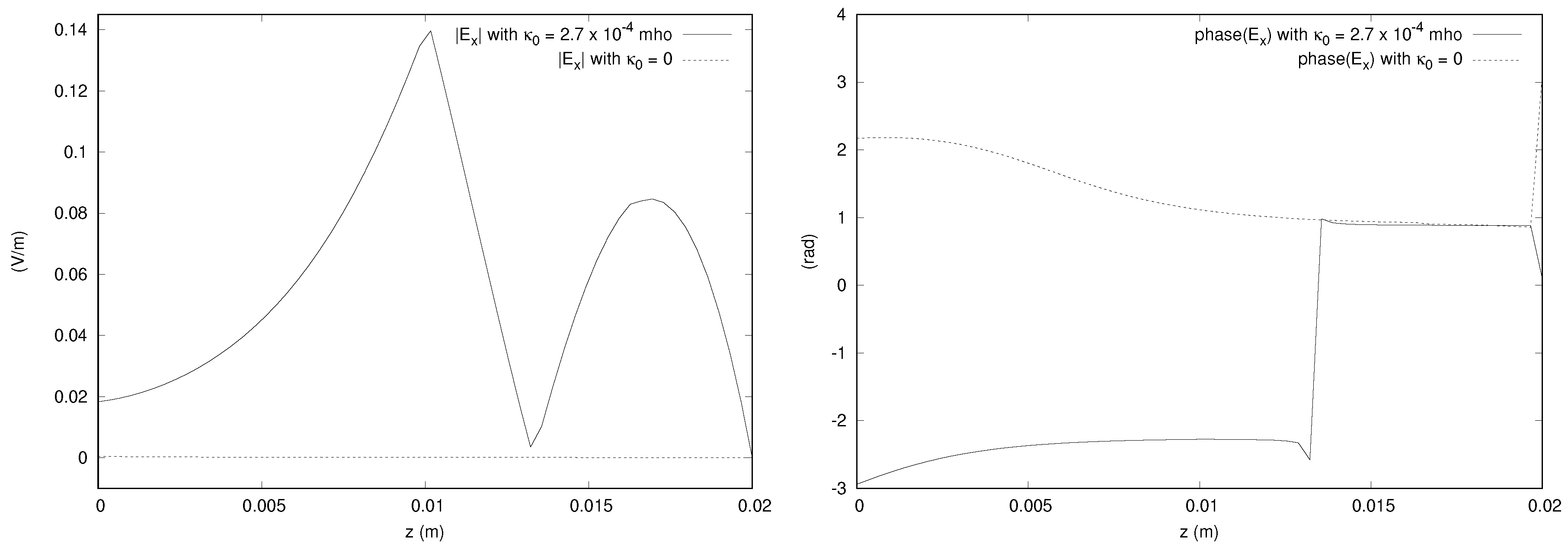
We provide the magnitudes and phases of the x component of the electric field obtained from the simulation in
Figure 15,
Figure 16 and
Figure 17. The bianisotropy causes a difference in magnitude of up to 14% of the incident field. The phases are also significantly affected by the bianisotropy of the medium. The figures for other components are not shown to save space, but it is noted that the y component is affected by the bianisotropy, showing a difference of up to about 10% of the incident field. The z component of the field along the line parallel to the
x axis passing through the center of gravity of the domain does show a difference of about 10% of the incident field, but the magnitudes along the other directions are close to zero for both values of
considered.
Since the theory guarantees the reliability of these results, they can be used as references for other solvers and approaches. It is to be noted that the previous theory developed in [
5] could not be applied to this medium since the same reasons mentioned there with respect to the medium in [
10] are valid. Hence, our results show the generality of the new theory with respect to the application to interesting bianisotropic media. The results demonstrate that our theory can be applied to problems with significant bianisotropic effects. This consideration underlines its practical importance.

