Abstract
This paper proposes a variable stiffness joint based on a symmetrical crank slider mechanism (SCM-VSJ). Firstly, the mechanical design and the working principle of the variable stiffness joint is described, and its stiffness regulation characteristics are studied. Secondly, the dynamical model of variable stiffness joint including joint motor, harmonic reducer and stiffness adjustment motor is established, in addition, the transmission mechanism of the crank slider mechanism and the elastic deformation of the spring bar are considered in the dynamic modeling. Finally, in order to control the dynamic stiffness of the variable stiffness joint in real time, a kind of improved PID (proportional-integral-derivative) control algorithm based on feed-forward and feedback closed-loop is proposed on the basis of the existing dynamical model, and the simulation analysis of real-time tracking control of dynamic stiffness for sinusoidal wave expected stiffness signal and random expected stiffness signal is carried out respectively. The research shows that the real-time stiffness control of SCM-VSJ can be realized effectively, and during the stiffness adjustment process, the output torque of the stiffness adjustment motor will be affected by the elastic deformation of the spring bar.
1. Introduction
Presently, the traditional rigid manipulator lacks enough environmental adaptability in various complex working environments, for example, in the case of human robot interaction. Human robot interaction is a key component of future robots, especially in the application of service robots, such as the care of the elderly and the disabled, deliver meals to guests in the restaurant. The direct contact between human and robot requires the robot to have enough safety, especially the mechanical safety of the robot itself. Therefore, more and more attention and research have been paid to the flexible manipulator. It is one of the main research directions to make the joints flexible of the robot [1,2,3]. If the joint stiffness of service robot is variable, when it is close to human, it can reduce the joint stiffness to increase the safety of human robot interaction, and when it is far from human, it can work with high joint stiffness. The main feature of the variable stiffness joint is that there are elastic elements with adjustable stiffness between the input and output of the actuator, which can convert the kinetic energy and elastic potential energy of the joint. Since the variable stiffness joint has great potential value for the future development of service robots, its mechanical design, dynamic performance, and real-time control of stiffness become the focus of research [4,5].
The SEA (Series Elastic Actuators) was proposed by Ratt et al. in 1995 [6]. Since then, many researchers have begun to study it and applied it to the joints of robots, and various variable stiffness joint have evolved and improved on the basis of SEA. According to the principle of variable stiffness of joints [7,8,9], the common variable stiffness joints are mainly of the following two types: antagonistic controlled variable stiffness joints and mechanically controlled variable stiffness joints. Antagonistic controlled stiffness originates from the antagonistic principle of biceps brachii and triceps brachii, the joints with similar principle and different structure are VSA (variable stiffness joint actuator) [10], AMASC (actuator with mechanically adjustable series compliance) [11], QA-Joint [12], this method requires more springs and complex structure. Mechanical controlled variable stiffness joints to changes joint stiffness by changing the connection between elastic elements and rigid structures, for example, VS-Joint [13], FSJ [14] and others adjust joint stiffness by change the preload of elastic elements; pVSJ (passive variable stiffness joint) [15], AwAS (actuator with adjustable stiffness) [16,17,18] and others [19,20,21,22] adjust joint stiffness by changing the effective length according to the lever principle. In addition, according to whether the stiffness of variable stiffness joint is continuous, it can be divided into continuous variable stiffness joint and discrete variable stiffness joint, such as BcVSA (Binary-Controlled Variable Stiffness Actuator) [23], pDVSJ (Passive Diskrete Variable Stiffness Joint) [24].
The variable stiffness joint may be helpful to improve the joint flexibility of the service robot. Therefore, it is necessary to put forward some requirements for the design of the variable stiffness joint according to the application of human robot interaction of the service robot. In the design of variable stiffness joint, the following factors should be taken into account: the joint output stiffness can change in a large range continuously, which is beneficial to improve the adaptability of the service robot to the working environment; the size of the joint should be as compact as possible and the lighter the better; the stiffness of the joint can be adjusted in real time, in some unexpected situations, the adjustment time of the stiffness is too long to guarantee the safety of human robot interaction.
In terms of the dynamics of variable stiffness joints, Ratt et al. first simplified the dynamics model of the variable stiffness joint drive system to a simple “power source-spring-load” model for analysis [6], in the subsequent studies, the dynamical models are gradually enriched, such as the VSA-II [25] proposed by Grioli, the damping factor is added to the dynamics. In the dynamical modeling of variable stiffness joints, the influence of motor damping should be taken into account, damping can play a very good restraining effect for the system with oscillation. We should also consider the effect of equivalent moment of inertia, which has great influence on the output characteristics of mechanical system. In addition, in practical applications, such as the motion of robot, the joint stiffness changes dynamically, and the dynamic stiffness will always affect the output characteristics of the joint. To establish a more complete dynamical model, the influence of the motor damping, equivalent moment of inertia, dynamic stiffness and reducer must be considered. Of course, for the specific variable stiffness drive joint, the transmission mechanism of the variable stiffness module and the elastic deformation of the elastic device also need to be considered in the dynamic modeling.
To adjust the dynamic characteristics of the robot in real time, it is necessary to identify and control the dynamic stiffness of the variable stiffness joint in real time and effectively. The joint stiffness value is not a physical quantity that can be directly measure, and its identification mainly come from the mathematical model of the system. Giorgio Drioli et al. used non-parametric model identification method and parametric model identification method respectively for variable stiffness joint actuator (VSA) [26,27,28], the results show that the parametric model identification method has better tracking performance for stiffness identification of non-linear characteristics. In addition, some studies show that the closed-loop control method is better than the open-loop control method for the variable stiffness system [29,30]. Therefore, on the basis of dynamic stiffness identification, the real-time dynamic value of joint stiffness is introduced into the control system as negative feedback, which can form a closed-loop stiffness control system and realize the dynamic real-time control of joint stiffness. Furthermore, in order to perform to the solution of the control system, some numerical optimization techniques proposed in [31,32] can be considered.
In this paper, a variable stiffness joint based on symmetrical crank slider mechanism is designed, and it can realize the continuous change of joint stiffness in a certain range. In Section 2, according to the service robot’s requirements for joint flexibility, the mechanical design of the variable stiffness joint is introduced in detail, the variable stiffness principle of the joint is expounded, and the mathematical derivation and characteristic analysis of SCM-VSJ are carried out. In Section 3, the dynamical model of variable stiffness joint actuator including joint motor, harmonic reducer and stiffness adjustment motor is established, in addition, we also consider the transmission mechanism of the crank slider mechanism and the elastic deformation of the spring bar in the dynamic modeling. Through dynamic simulation, the characteristic curves of the output angle, angular velocity, and torque of the joint under different stiffness are obtained. In Section 4, a kind of improved PID closed-loop control algorithm of joint stiffness based on feed-forward and feedback is proposed, and real-time tracking control simulation is carried out for sine wave expected stiffness signal and random expected stiffness signal respectively, which verifies the feasibility of the proposed control method. Finally, the summary of the research work and the prospect of the future work are given.
2. Mechanical Design and Mathematical Analysis of SCM-VSJ
Many human robot interaction scenarios of service robots require that the stiffness of robot joints can be continuously changed from minimal to maximal, and the change of stiffness can be completed in a very short time. Our design of variable stiffness joint is based on this requirement. Considering the principle of saving energy consumption when the joint stiffness is constant, we choose to change the joint stiffness continuously by changing the effective length of the spring bar according to the lever principle. Considering the rapidity requirements of service robots for stiffness adjustment, we adopt the crank slider mechanism. Compared with other mechanisms such as ball screw mechanism, the crank slider mechanism can quickly adjust the effective length of the spring bar and achieve the required joint stiffness faster. The following is a detailed introduction to the mechanical design and characteristic analysis of SCM-VSJ.
2.1. Mechanical Design
The mechanical design structure of SCM-VSJ is shown in Figure 1. The joint motor can drive the input disk to rotate through the reducer, the center of the spring bar is fixed with the center of the input disk. Both ends of the spring bar pass through the circular holes on both sides of the output disk, and the output bar is fixed to the output disk. Therefore, the joint motor can drive the output disk through the spring bar to realize joint position control. The stiffness adjustment motor is fixed on the connecting bracket of the input disk, after driving the stiffness adjustment motor, a pair of crank slider mechanisms can move symmetrically left and right through gear meshing transmission, therefore, a pair of sliding clamps can slide symmetrically left and right in the convex groove of the input disk. The contact force pivot point is formed by the contact between the sliding clamp and the spring bar, the driving stiffness adjustment motor can make the contact force pivot point of the left and right sides of the spring bar move symmetrically at the same time, and change the effective length of the spring bar, thereby changing the joint stiffness. We use symmetrical structure to change the stiffness of the joint, when the joint is subjected to external moment, the load impact on all parts of the joint will be more balanced. To prevent the spring bar from plastic deformation caused by excessive deformation, a baffle is set on the input disk and a U-shaped groove is arranged on the output disk.
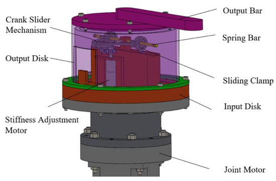
Figure 1.
Structural model of SCM-VSJ.
When the stiffness adjustment motor rotates, the sliding clamp slides on the spring bar, as shown in Figure 2a. When the joint is subjected to the external moment, and the position of the sliding clamp remains unchanged, the larger the external moment is, the larger the elastic deformation of the spring bar is, as shown in Figure 2b.
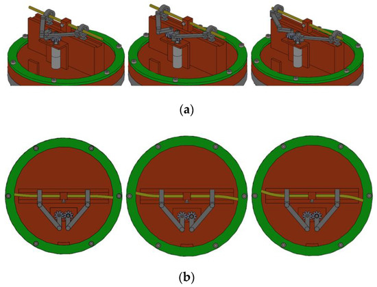
Figure 2.
Schematic diagram of crank slider movement and spring bar bending. (a) Different positions of the sliding clamp. (b) Bending diagram of spring bar.
When using the crank slider mechanism, it is necessary to optimize the dimensions of the crank slider mechanism. Take the optimal transmission angle of crank slider mechanism as the optimization objective, optimize the dimensions of , and is shown in Figure 3. is the length of the crank, is the length of connecting rod, which connect crank and slider, is the eccentricity of the crank slider mechanism, is the slider stroke of the crank slider mechanism, is the polar angle of the crank slider mechanism, is the minimum transmission angle of the crank slider mechanism.
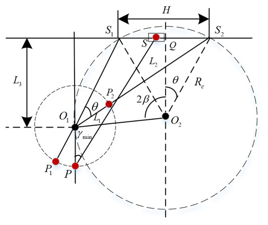
Figure 3.
Dimensions optimization of slider crank mechanism.
Set , , require the best transmission angle, then the calculation process is as follows:
Then the dimensions of , and are calculated as follows:
The optimized minimum transmission angle can be obtained.
According to the above optimization, we choose the dimensions of , and as follows:
Now, the minimum transmission angle of the crank slider mechanism is , which meets the transmission requirements of the crank slider mechanism.
We choose the servo motor as the joint motor, and use the harmonic reducer to reduce the speed. In addition, we choose a DC geared motor as the stiffness adjustment motor, which is required to provide enough torque to drive the movement of the sliding clamp. The parameters of motor and reducer are shown in Table 1.

Table 1.
Parameters of motor and reducer.
In the structure of SCM-VSJ, there will be friction in the movement of slider crank mechanism, which will affect the torque requirements of the actuator and the performance of the system. The influence of friction will be considered in the system dynamics modeling. In addition, as shown in Figure 2b, when the joint is subjected to the external moment, the elastic deformation of the spring bar will cause resistance to the sliding of the sliding clamp, which affects the torque output of the stiffness adjustment motor.
The transmission of the crank slider mechanism affects the adjustment of the joint stiffness, and a model needs to be established to calculate the relationship between the position of the sliding clamp and the rotation angle of the stiffness adjustment motor. To realize the real-time adjustment of joint stiffness, dynamic modeling of joints is necessary, which is based on joint stiffness calculation and crank slider transmission modeling. These will be discussed in detail in later section.
2.2. Mathematical Derivation
The core of the design is the principle of variable stiffness of the lever structure, but its structural design is novel and simple. The schematic diagram of the stiffness adjustment of SCM-VSJ is shown in Figure 4.
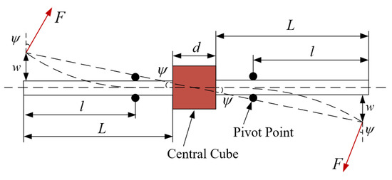
Figure 4.
Stiffness adjustment schematic diagram of SCM-VSJ.
The contact force pivot point is symmetrically distributed and can slide left and right along the spring bar. is the length from one side of the spring bar to the central cube, is the distance between the pivot point and the end of the spring bar, which serves as the variable effective length of the spring bar, is the side length of the central cube that is used to fix the spring bar. When the external force is applied, the spring bar will bend because of the torque, and the passive deflection angle of the output shaft of the variable stiffness joint is . The deflection of the both ends of the spring bar is equal and the direction is opposite.
We take the right half of the spring bar as an example to make a mathematical analysis of the variable stiffness joint.
When the external moment is applied, the force is applied perpendicular to the circumference of the spring bar. The torsional stiffness of the joint produced by the spring bar in the right half is calculated as follows:
The deflection of spring bar under external force is approximately as follows:
Since one end of the right part of the spring bar is fixed on the central cube and the other end is subjected to concentrated load, and there is a movable contact force pivot point between the sliding clamp and the spring bar, the structure of the spring bar is a cantilever beam at this time. According to material mechanics, the maximum deflection of the free end of a cantilever beam can be obtained by superposition principle.
To calculate the end deflection of the spring bar which is the maximum free end deflection of a cantilever beam subjected to concentrated loads, the above-mentioned stressed structure is shown in Figure 5.
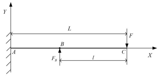
Figure 5.
Schematic diagram of the cantilever beam under concentrated load.
The cantilever beam structure in Figure 4 has two points of application under concentrated loads. is the force at the end of the spring bar under the action of external torque, which can be regarded as a concentrated load. is the concentrated load exerted by the contact pivot point on the spring bar when the spring bar bends under the external moment. Therefore, the force structure of the cantilever beam is composed of two simple load cantilever beam structures, as shown in Figure 6.
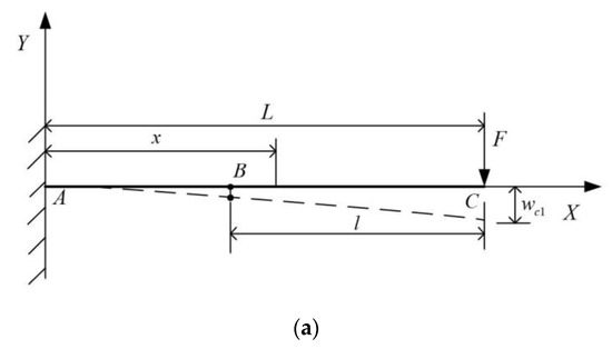
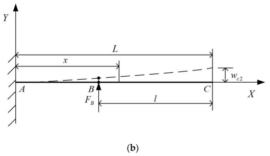
Figure 6.
(a) The concentrated load is applied only at the rightmost end C of the cantilever beam. (b) Only a point B on the cantilever beam is subjected to concentrated load.
The deflection formula of beam under simple load can be obtained by looking up the table. The deflection curve formula of cantilever beam in Figure 6a is as follows:
The deflection curve formula of cantilever beam in Figure 6b is as follows:
where is any point on the cantilever beam, is the elastic modulus of the spring bar, and is the moment of inertia of the cross section of the spring bar to the bending neutral axis under external force.
For the cantilever beam in Figure 6a, when , the deflection at the right end C of the cantilever beam is as follows:
When , the deflection at point B of the cantilever beam is as follows:
For the cantilever beam in Figure 6b, when , the deflection at the right end C of the cantilever beam is as follows:
When , the deflection at point B of the cantilever beam is as follows:
When SCM-VSJ is subjected to external load, the deflection at the point B is zero due to the restraint of sliding clamp on spring bar. According to the principle of cantilever beam superposition, the equation is as follows:
According to Equation (13), the calculation of is as follows:
Then, according to Equations (11) and (14), the calculation of is as follows:
According to the superposition principle of the cantilever beam, the deflection at point C is:
By calculation, the deflection at the rightmost end C of the spring bar is as follows:
The shape of the cross section of the selected spring bar is circular, assuming that the diameter of the cross section of the spring bar is , the moment of inertia is calculated as follows:
According to Equations (6), (17) and (18), the calculation of the external force is as follows:
The external torque is calculated as follows:
According to Equations (5) and (20), The torsional stiffness of the joint produced by the spring bar in the right half is calculated as follows:
As the contact forces pivot point on the left and right sides is symmetrically distributed, the spring bar on the left and right sides of the central cube has the same effect on the torsional stiffness of the joint, i.e., .
Therefore, the stiffness of the variable stiffness joint is calculated as follows:
It can be seen from Equation (22) that the stiffness of the variable stiffness joints is related to the material, shape, effective length of the spring bar and the passive deflection angle of the joint.
In this paper, the effective length of the spring bar is changed by means of symmetrical crank slider mechanism. The relationship between the effective length and the rotation angle of the stiffness adjustment motor is shown in Figure 7.
Figure 7.
Schematic diagram of the crank slider mechanism.
In Figure 7, is the distance between the gear shaft and the joint center point O along the slideway direction, is the distance between the contact force pivot point B and the reference point A, effective length is the distance between rightmost point C of the spring bar and the contact force pivot point B, and is the angle between connecting rod and slideway.
To calculate the effective length , the length of can be calculated first. According to Figure 7, we can see that:
According to Equation (23), we can get that:
The length of is calculated as follows:
Then, the effective length can be calculated as follows:
The stiffness of the variable stiffness joint can be derived from Equations (22) and (27).
2.3. Characteristic Analysis
Next, we analyze the characteristics of SCM-VSJ based on its design parameters and its stiffness adjustment formula. After optimization design of dimension parameters, the design parameters of SCM-VSJ are shown in Table 2.
Table 2.
Parameters of SCM-VSJ.
Substitute the parameters of Table 2 into Equation (27), the relationship between the effective length and the rotation angle of the stiffness motor can be obtained. To prevent interference of symmetrical crank slider mechanism, the range of stiffness motor rotation angle is set between [0°, 190°]. The relationship between effective length and stiffness motor rotation angle is shown in Figure 8.
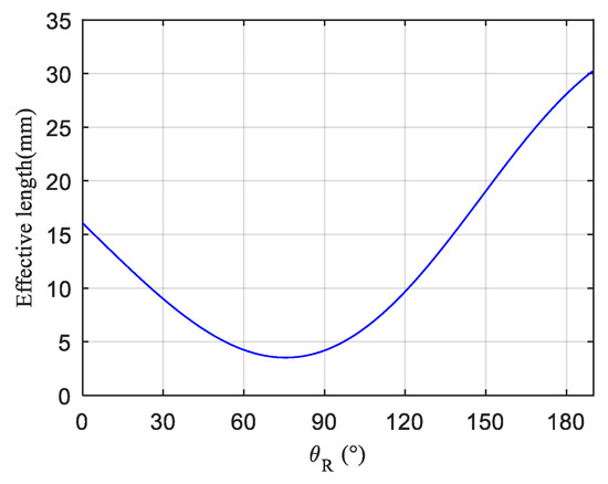
Figure 8.
The relationship between effective length and stiffness motor angle.
It can be seen from Figure 8 that the effective length of the spring bar increases gradually when the rotation angle of the stiffness motor is between [120°, 190°], and the movement of the crank slider in the above range will not cause interference between the mechanisms, so a reasonable range of stiffness motor rotation angle is [120°, 190°], and the range of effective length is [9.6 mm, 30.2 mm].
Considering the rated torque of the reducer of the joint motor and the adjustment range of the effective length, according to Equation (16), we can get the relationship between the passive deflection angle and the external torque and the effective length, as shown in Figure 9.
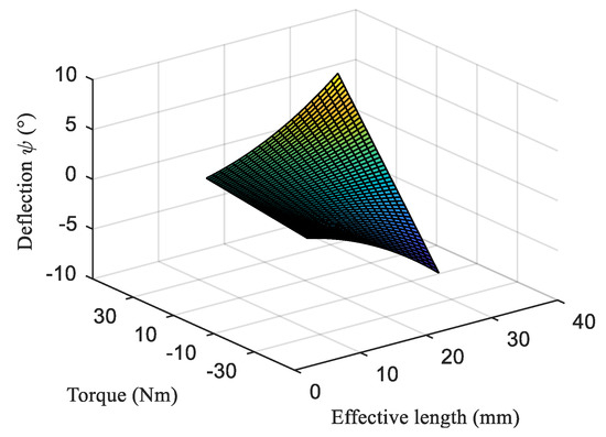
Figure 9.
The relationship between the passive deflection angle and the external torque and the effective length.
As can be seen from Figure 9, when the external torque is less than the rated torque of the reducer of the joint motor, no matter how we adjust the effective length of the spring bar, the maximum passive deflection angle is not more than 8°, which is why we limit the range of passive deflection angle to [−8°, 8°].
Substitute the parameters of Table 2 into Equation (22), the relationship between the joint stiffness and the effective length and the passive deflection angle can be obtained, as shown in Figure 10.
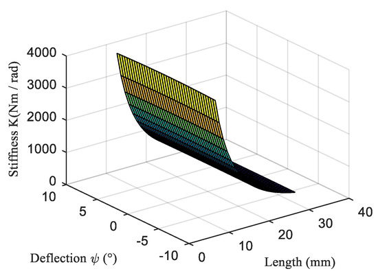
Figure 10.
The relationship between the joint stiffness and the effective length and the passive deflection angle.
As can be seen from Figure 10, the joint stiffness is mainly affected by the effective length, which has little relationship with the passive deflection angle. The effective length of the spring bar is inversely proportional to the joint stiffness, the stiffness range of the SCM-VSJ is [368, 3968], and the unit is .
When the joint is subjected to high load, the spring bar will bend and produce elastic deformation. In this case, we should discuss how the driving torque of the stiffness adjustment motor will be affected when the sliding clamp slides on the spring bar to adjust the stiffness.
According to Equations (14) and (20), the force between the spring bar and the sliding clamp is calculated as follows:
Considering the friction between sliding clamp and spring bar, when the sliding clamp slides on the spring bar, the elastic deformation of the spring bar will increase the resistance to sliding. To overcome the resistance, it is necessary to increase the driving torque of the stiffness adjustment motor. The resistance moment formed by the resistance to the stiffness adjustment motor is shown in Figure 11.
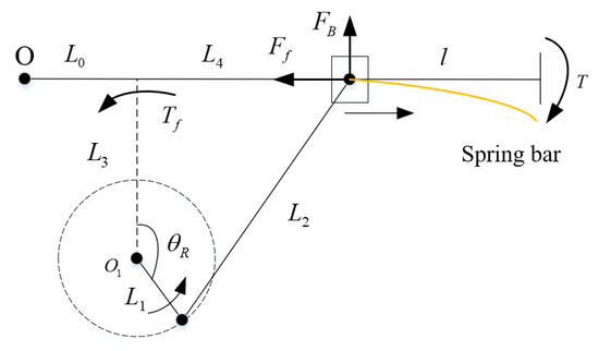
Figure 11.
Schematic diagram of resistance moment.
Where is the resistance, is the resistance moment of the resistance to the stiffness adjustment motor. Then we can calculate the resistance moment as follows:
where is the sliding friction coefficient between the sliding clamp and the spring bar.
We assume the external moment , the coefficient of sliding friction , then we can get the resistance moment that must be overcome when the sliding clamp slides on the spring bar, as shown in Figure 12.
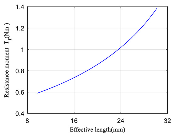
Figure 12.
The relationship between resistance moment and effective length.
It can be seen from Figure 12 that the longer the effective length is, the greater the resistance moment that the stiffness adjustment motor must overcome when the external moment is constant. In other words, the smaller the joint stiffness is, i.e., the larger the elastic potential energy of the spring bar is, the greater the resistance moment that the stiffness adjustment motor must overcome. We can think that when the sliding clamp slides toward the bending direction of the spring bar, the elastic potential energy of the spring bar decreases gradually, and the resistance moment to be overcome also decreases gradually. When the sliding clamp slides toward the non-bending direction of the spring bar, the work done to overcome the resistance is converted into the elastic potential energy of the spring bar, and the elastic potential energy of the spring bar increases gradually.
The performance of SCM-VSJ is compared with other variable stiffness joint, as shown in Table 3 [33].
Table 3.
Parameter comparison among several variable stiffness joints.
3. Dynamics Analysis of SCM-VSJ
3.1. Dynamical Model
The variable stiffness joint drive system based on symmetrical crank slider mechanism is mainly composed of joint motor, harmonic reducer, input shaft, stiffness adjustment module, and output shaft. In the dynamic modeling, we should consider the electrical damping of the motor, the output damping, and the reduction ratio of the harmonic reducer. In addition, we should also consider the friction in the movement of crank slider mechanism and elastic deformation of spring bar, which will also affect the torque requirements of the actuator and the performance of the system. Combining the above factors, the dynamical model of the variable stiffness joint drive system is established as shown in Figure 13.
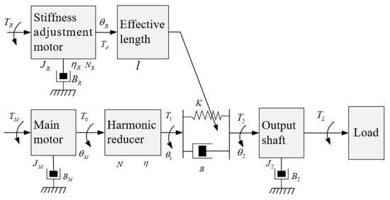
Figure 13.
Dynamical Model of SCM-VSJ.
The dynamic equations of SCM-VSJ are as follows:
The meanings of parameters in Equation (30) are shown in Table 4.
Table 4.
The meaning of each parameter in the dynamical model of SCM-VSJ.
3.2. Dynamics Characteristics of SCM-VSJ
According to Equation (22) and Equations (28)–(30), the visual block diagram of dynamical model of the variable stiffness joint is established by MATLAB/Simulink, and its dynamics characteristics are simulated and analyzed.
Assuming that the joint is subjected to a certain external load, , and input torque of main motor is rated torque, when the joint stiffness takes different values, the response curves of joint output angle, angular velocity and output torque are shown in Figure 14, Figure 15 and Figure 16 respectively.
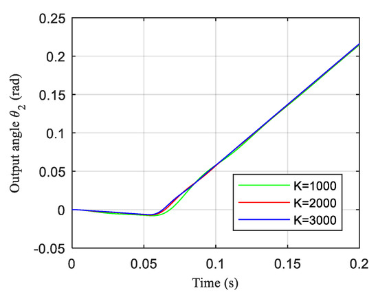
Figure 14.
The response curve of the joint output angle.
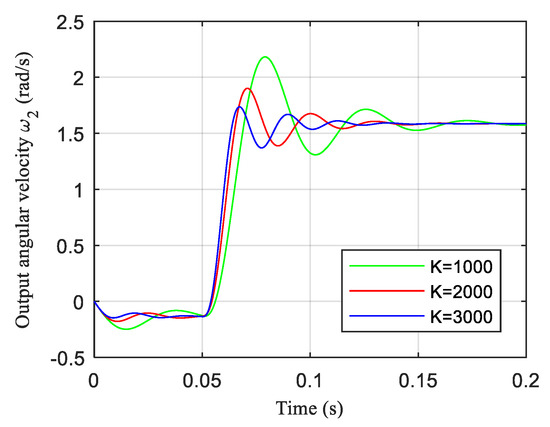
Figure 15.
The response curve of the output angular velocity.

Figure 16.
The response curve of the joint output torque.
As can be seen from Figure 14, the joint output angle increases gradually from 0. When the stiffness of the joint is small, the response curve of the output angle of the joint with time will fluctuate greatly. When the joint stiffness is large, the curve of the output angle of the joint with time is close to the linear curve.
It can be seen from Figure 15 that the output angular velocity of the joint increases from 0 until it eventually stabilizes, but the whole process shows large fluctuation. When the stiffness is small, the angular velocity fluctuates greatly, which takes a long time to stabilize. When the stiffness is large, the angular velocity fluctuates less and the response speed is faster.
As can be seen from Figure 16 that the output torque of the joint increases from 0 until it eventually stabilizes, but the whole process shows great fluctuation. The lower the stiffness, the greater the fluctuation of the output torque.
4. Real-Time Dynamics Stiffness Control of SCM-VSJ
To realize the real-time change of joint stiffness according to the needs of the environment during the movement of the robot, it is necessary to control the dynamic stiffness of the joint with variable stiffness.
For the real-time control of dynamic stiffness of SCM-VSJ, this paper proposes an improved PID control method based on feedforward and feedback closed-loop. The block diagram of the control system is shown in Figure 17.
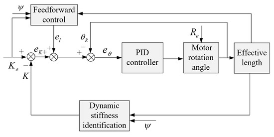
Figure 17.
Block diagram of closed-loop control system of SCM-VSJ.
Where is the passive deflection angle, which can be obtained in real time through encoder measurement, and it is a known quantity; is the expected stiffness of the joint, is the random disturbance.
Given the expected stiffness and the passive deflection angle , according to Equation (22), the expected effective length can be calculated as follows:
The feedforward control is to introduce the difference between the expected effective length and the actual effective length regulated by the stiffness adjustment motor into the control system. The feedback control is to introduce the difference between the expected stiffness and the actual calculated stiffness into the control system. The control of the rotation angle of the stiffness adjustment motor is a closed-loop feedback control with random disturbance . The stiffness adjustment motor is disturbed randomly, and the difference between the expected rotation angle of the stiffness adjustment motor and the actual rotation angle of the stiffness adjustment motor is , then we can get the expected torque of the stiffness adjustment motor by PID control. According to the dynamical model of stiffness adjustment motor in Equation (30), the rotation angle of stiffness adjustment motor can be controlled.
The relevant variables are calculated as follows:
According to the control method shown in Figure 17, the visual block diagram of SCM-VSJ closed-loop PID control based on feedforward and feedback is established by MATLAB/Simulink, and the simulation analysis of real-time dynamic tracking of joint stiffness is carried out to verify the effectiveness of the proposed method. The simulation parameters of SCM-VSJ are shown in Table 5.
Table 5.
The simulation parameters of SCM-VSJ.
How to choose the gain of PID is a very important issue, which has a great influence on the control effect of the system. We use PID Tuner in Simulink to adjust PID parameters, and select to adjust PID gain in time domain, and adjust response time and transient behavior to obtain PID gain automatically. We hope that the closed-loop control system has good stability, fast response speed for reference signal, and a small overshoot in the response curve.
After the PID parameters are automatically adjusted, the overshoot of the response curve is 10.3%, rise time is 0.0299 s and setting time is 0.329 s. The tuned response curve is shown in Figure 18.
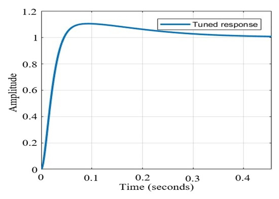
Figure 18.
The tuned response curve.
The real-time tracking control of dynamic stiffness for sinusoidal wave expected stiffness signal and random expected stiffness signal is carried out respectively. We assume that the joint is subjected to a certain external load, , and input torque of main motor is rated torque, a random disturbance is given to the system, running time is set to 2 s. When the expected joint stiffness is a sine wave signal, ; When the expected joint stiffness is a random signal, we assume that it is a random curve with an average stiffness value of and a variance of .
Real-time dynamic stiffness tracking curve is shown in Figure 19, whether it is tracking the sine wave expected stiffness curve or a given random expected stiffness curve, the improved PID closed-loop control method based on feedforward and feedback can effectively track the expected stiffness curve in real time, and the average error of the stiffness tracking is less than 5%.
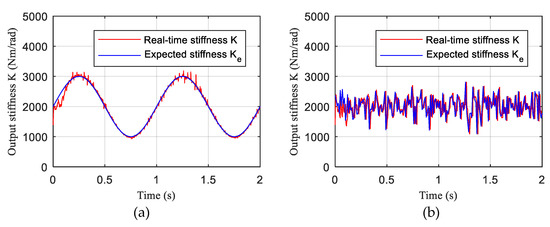
Figure 19.
Real-time dynamic stiffness tracking curve. (a) The expected joint stiffness is a sine wave signal. (b) The expected joint stiffness is a random signal.
During the tracking control of dynamic stiffness, the joint passive deflection angle is also changing in real time due to the change of joint stiffness, as shown in Figure 20. Whether it is tracking a sine wave expected stiffness signal or a random expected stiffness signal, the change in passive deflection angle conforms to such a rule, i.e., when the expected tracking stiffness becomes larger, the passive deflection angle becomes smaller, and vice versa.
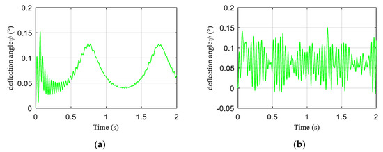
Figure 20.
The curve of joint passive deflection angle during stiffness tracking. (a) The expected joint stiffness is a sine wave signal. (b) The expected joint stiffness is a random signal.
The change of joint output torque is shown in Figure 21. Whether it is tracking the sine wave expected stiffness signal or the random expected stiffness signal, the output torque of the joint motor will tend to the magnitude of the load torque.
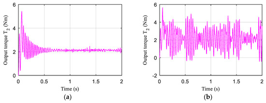
Figure 21.
The output torque curve of the joint during stiffness tracking. (a) The expected joint stiffness is a sine wave signal. (b) The expected joint stiffness is a random signal.
As can be seen from Figure 22, whether it is tracking the sine wave expected stiffness signal or a random expected stiffness signal, the output torque of the stiffness adjustment motor will change with the change of the expected stiffness. When the expected tracking stiffness increase, the output torque of the stiffness adjustment motor decreases and vice versa. This is in accordance with the rule shown by the sliding clamp when sliding on the spring bar, i.e., when the joint stiffness increases, the elastic potential energy of the spring bar decreases, and the resistance moment that the sliding clamp must overcome when sliding on the spring bar decreases. Since the stiffness is always changing, the output torque of the stiffness adjustment motor always shows fluctuation.
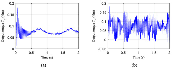
Figure 22.
The output torque curve of the stiffness adjustment motor during stiffness tracking. (a) The expected joint stiffness is a sine wave signal. (b) The expected joint stiffness is a random signal.
5. Conclusions
In this paper, a variable stiffness joint SCM-VSJ based on a symmetrical crank slider mechanism is proposed. The effective length of the spring bar is adjusted by the crank slider mechanism to change the stiffness of joint.
Taking SCM-VSJ as the research object, we proposed the mechanical design model of SCM-VSJ and optimized the dimensions of the crank slider mechanism. During the mathematical derivation and characteristic analysis of the stiffness, we found that in the process of adjusting the stiffness, due to the potential energy difference caused by elastic deformation of the spring bar, the resistance moment that must be overcome in the movement of the crank slider mechanism changes in real time. The dynamical model including motor and harmonic reducer is established, and the dynamic characteristics are simulated and analyzed. For the dynamic modeling of SCM-VSJ, it is also necessary to consider the friction in the movement of crank slider mechanism and elastic deformation of spring bar, which will affect the torque requirements of the actuator and the performance of the system. The simulation results show that the response curves of joint output angle, angular velocity and output torque are different under the same driving torque and load and different stiffness. The smaller the stiffness is, the slower the response is, and the longer it takes to reach a stable state.
The dynamic stiffness control method of SCM-VSJ is studied, and the dynamic stiffness of the joint can be tracked in real time by adopting a kind of improved PID closed-loop control algorithm based on feedforward and feedback. We track and control the sine wave expected stiffness signal and random expected stiffness signal respectively, and get the stiffness tracking curve, passive deflection angle curve, joint output torque curve and stiffness adjustment motor output torque curve. The results show that the real-time tracking of expected stiffness can be realized, but it is more difficult to track the random expected stiffness signal. In addition, in the process of stiffness tracking, whether the joint output torque curve, the stiffness adjustment motor output torque curve or the passive deflection angle curve all conforms to the dynamic characteristics of SCM-VSJ.
In the future research work, it is our research goal to apply variable stiffness joints to service robots, and we hope to improve the environmental adaptability of robot. Of course, the joint dynamic stiffness control methods may be diverse, how to choose a good control method to control the stiffness of joints is an interesting problem, which requires us to further study. In addition, the reasonable design of variable stiffness joint is also the work we will continue to do.
Author Contributions
Funding acquisition, S.W.; Methodology, Y.Y.; Supervision, Z.Y.; Writing—original draft, Y.Y.; Validation, Q.J.; Writing—review & editing, S.W., Q.J. and Z.Y. All authors have read and approved the final paper. All authors have read and agreed to the published version of the manuscript.
Funding
This work was supported by the Beijing Municipal Natural Science Foundation under Grant L172031.
Conflicts of Interest
The authors declare that there are no conflict of interest.
References
- Wolf, S.; Bahls, T.; Chalon, M.; Friedl, W.; Grebenstein, M.; Höppner, H.; Kühne, M.; Lakatos, D.; Mansfeld, N.; Özparpucu, M.C.; et al. Soft robotics with variable stiffness actuators: Tough robots for soft human robot interaction. In Soft Robotics; Verl, A., Albu-Schäffer, A., Brock, O., Raatz, A., Eds.; Springer: Berlin/Heidelberg, Germany, 2015; pp. 231–254. [Google Scholar]
- Velasco, A.; Garabini, M.; Catalano, M.G.; Bicchi, A. Soft actuation in cyclic motions: Stiffness profile optimization for energy efficiency. In Proceedings of the 2015 IEEE-RAS 15th International Conference on Humanoid Robots (Humanoids), Seoul, Korea, 3–5 November 2015; pp. 107–113. [Google Scholar]
- Chu, M.; Wu, X. Modeling and Self-learning Soft-grasp Control for Free-floating Space Manipulator during Target Capturing using Variable Stiffness Method. IEEE Access 2018, 6, 7044–7054. [Google Scholar] [CrossRef]
- Uemura, M.; Kawamura, S. Resonance-based motion control method for multi-joint robot through combining stiffness adaptation and iterative learning control. In Proceedings of the 2009 IEEE International Conference on Robotics and Automation, Kobe, Japan, 12–17 May 2009; pp. 1543–1548. [Google Scholar]
- Ye, X.; Hong, J.-C.; Dong, Z.-H. Research on Angle and Stiffness Cooperative Tracking Control of VSJ of Space Manipulator Based on LESO and NSFAR Control. Electronics 2019, 8, 893. [Google Scholar] [CrossRef]
- Pratt, G.A.; Williamson, M.M. Series elastic actuators. In Proceedings of the IEEE/RSJ International Conference on Intelligent Robots and Systems, Pittsburgh, PA, USA, 5–9 August 1995; pp. 399–406. [Google Scholar]
- van Ham, R.; Sugar, T.G.; Vanderborght, B.; Hollander, K.W.; Lefeber, D. Compliant actuator designs. IEEE Robot. Autom. Mag. 2009, 16, 81–94. [Google Scholar]
- Tagliamonte, N.L.; Sergi, F.; Accoto, D.; Carpino, G.; Guglielmelli, E. Double actuation architectures for rendering variable impedance in compliant robots: A review. Mechatronics 2012, 22, 1187–1203. [Google Scholar] [CrossRef]
- Wolf, S.; Grioli, G.; Eiberger, O.; Friedl, W.; Grebenstein, M.; Höppner, H.; Burdet, E.; Caldwell, D.G.; Carloni, R.; Catalano, M.G.; et al. Variable Stiffness Actuators: Review on Design and Components. IEEE/ASME Trans. Mechatron. 2016, 21, 2418–2430. [Google Scholar] [CrossRef]
- Tonietti, G.; Schiavi, R.; Bicchi, A. Design and control of a variable stiffness actuator for safe and fast physical human/robot interaction. In Proceedings of the IEEE Int. Conf. on Robotics and Automation, Barcelona, Spain, 18–22 April 2005; pp. 528–533. [Google Scholar]
- Hurst, J.W.; Chestnutt, J.; Rizzi, A.A. The actuator with mechanically adjustable series compliance. IEEE Trans. Robot. 2010, 26, 597–606. [Google Scholar] [CrossRef]
- Eiberger, O.; Haddadin, S.; Weis, M.; Albu-Schäffer, A.; Hirzinger, G. On joint design with intrinsic variable compliance: Derivation of the DLR QA-Joint. In Proceedings of the IEEE International Conference on Robotics and Automation (ICRA 2010), Anchorage, AK, USA, 3–7 May 2010; pp. 1687–1694. [Google Scholar]
- Wolf, S.; Hirzinger, G. A new variable stiffness design: Matching requirements of the next robot generation. In Proceedings of the IEEE International Conf. on Robotics and Automation (ICRA), Pasadena, CA, USA, 19–23 May 2008; pp. 1741–1746. [Google Scholar]
- Wolf, S.; Eiberger, O.; Hirzinger, G. The DLR FSJ: Energy based design of a variable stiffness joints. In Proceedings of the IEEE International Conference on Robotics and Automation (ICRA), Shanghai, China, 9–13 May 2011; pp. 5082–5089. [Google Scholar]
- Awad, M.I.; Gan, D.; Cempini, M.; Cortese, M.; Vitiello, N.; Dias, J.; Dario, P.; Seneviratne, L. Modeling, design and characterization of a novel passive variable stiffness joint (pVSJ). In Proceedings of the IEEE/RSJ International Conference on Intelligent Robots and Systems (IROS), Daejeon, Korea, 9–14 October 2016; pp. 323–329. [Google Scholar]
- Jafari, A.; Tsagarakis, N.; Vanderborght, B.; Caldwell, D. A novel actuator with adjustable stiffness (AwAS). In Proceedings of the IEEE/RSJ international conference on intelligent robots and systems (IROS 2010), Taipei, Taiwan, 18–22 October 2010; pp. 4201–4206. [Google Scholar]
- Jafari, A.; Tsagarakis, N.G.; Caldwell, D.G. AwAS-II: A new Actuator with Adjustable Stiffness based on the novel principle of adaptable pivot point and variable lever ratio. In Proceedings of the 2011 IEEE International Conference on Robotics and Automation, Shanghai, China, 9–13 May 2011. [Google Scholar]
- Jafari, A.; Tsagarakis, N.G.; Sardellitti, I.; Caldwell, D.G. A New Actuator with Adjustable Stiffness Based on a Variable Ratio Lever Mechanism. IEEE/ASME Trans. Mechatron. 2014, 19, 55–63. [Google Scholar] [CrossRef]
- Choi, J.; Hong, S.; Lee, W.; Kang, S.; Kim, M. A Robot Joint with Variable Stiffness Using Leaf Springs. IEEE Trans. Robot. 2011, 27, 229–238. [Google Scholar] [CrossRef]
- Groothuis, S.; Carloni, R.; Stramigioli, S. A Novel Variable Stiffness Mechanism Capable of an Infinite Stiffness Range and Unlimited Decoupled Output Motion. Actuators 2014, 3, 107–123. [Google Scholar] [CrossRef]
- Vanderborght, B.; Tsagarakis, N.G.; Van Ham, R.; Thorson, I.; Caldwell, D.G. MACCEPA 2.0: Compliant actuator used for energy efficient hopping robot Chobino1D. Auton. Robot. 2011, 31, 55–65. [Google Scholar] [CrossRef]
- Fumagalli, M.; Barrett, E.; Stramigioli, S.; Carloni, R. The mVSA-UT: A miniaturized differential mechanism for a continuous rotational variable stiffness actuator. In Proceedings of the 2012 4th IEEE RAS & EMBS International Conference on Biomedical Robotics and Biomechatronics (BioRob), Rome, Italy, 24–27 June 2012; pp. 1943–1948. [Google Scholar]
- Hussain, I.; Albalasie, A.; Awad, M.I.; Seneviratne, L.; Gan, D. Modeling, Control, and Numerical Simulations of a Novel Binary-Controlled Variable Stiffness Actuator (BcVSA). Front. Robot. AI 2018, 5, 68. [Google Scholar] [CrossRef]
- Awad, M.I.; Gan, D.; Thattamparambil, J.; Stefanini, C.; Dias, J.; Seneviratne, L. Novel passive Diskrete Variable Stiffness Joint (pDVSJ): Modeling, design, and characterization. In Proceedings of the IEEE International Conference on Robotics and Biomimetics, Qingdao, China, 3–7 December 2016; pp. 1808–1813. [Google Scholar]
- Schiavi, R.; Grioli, G.; Sen, S.; Bicchi, A. VSA-II: A novel prototype of variable stiffness actuator for safe and performing robots interacting with humans. In Proceedings of the IEEE International Conference on Robotics & Automation IEEE, Pasadena, CA, USA, 19–23 May 2008; pp. 2171–2176. [Google Scholar]
- Grioli, G.; Bicchi, A. A non-invasive, real-time method for measuring variable stiffness. In Robotics: Science and Systems Vi; Universidad De Zaragoza: Zaragoza, Spain, June 2010; Volume 6, pp. 89–96. [Google Scholar]
- Grioli, G.; Bicchi, A. A real-time parametric stiffness observer for VSA devices. In Proceedings of the 2011 IEEE International Conference on Robotics and Automation, Shanghai, China, 9–13 May 2011; pp. 5535–5540. [Google Scholar]
- Flacco, F.; de Luca, A.; Sardellitti, I.; Tsagarakis, N.G. Robust estimation of variable stiffness in flexible joints. In Proceedings of the 2011 IEEE/RSJ International Conference on Intelligent Robots and Systems, San Francisco, CA, USA, 25–30 September 2011; pp. 4026–4033. [Google Scholar]
- Zhakatayev, A.; Rubagotti, M.; Varol, H.A. Closed-Loop Control of Variable Stiffness Actuated Robots via Nonlinear Model Predictive Control. IEEE Access 2015, 3, 235–248. [Google Scholar] [CrossRef]
- Albu-Schaffer, A.; Wolf, S.; Eiberger, O.; Haddadin, S.; Petit, F.; Chalon, M. Dynamic modelling and control of variable stiffness actuators. In Proceedings of the 2010 IEEE International Conference on Robotics and Automation, Anchorage, AK, USA, 3–7 May 2010; pp. 2155–2162. [Google Scholar]
- Andrea, C.; Giovanni, F.; Massimo, R. Preconditioning Strategies for Nonlinear Conjugate Gradient Methods, Based on Quasi-Newton Updates. In Proceedings of the AIP Conference Proceedings, Pizzo Calabro, Italy, 19–25 June 2016; Sergeyev, Y., Kvasov, D., Dell’Accio, F., Mukhametzhanov, M., Eds.; Volume 1776, pp. 090007-1–090007-4. [Google Scholar]
- Al-Baali, M.; Caliciotti, A.; Fasano, G.; Roma, M. Quasi-Newton Based Preconditioning and Damped Quasi-Newton Schemes for Nonlinear Conjugate Gradient Methods. In Numerical Analysis and Optimization. NAO 2017; Al-Baali, M., Grandinetti, L., Purnama, A., Eds.; Springer Proceedings in Mathematics & Statistics; Springer: Cham, Switzerland, 2018; Volume 235. [Google Scholar]
- Groothuis, S.S.; Rusticelli, G.; Zucchelli, A.; Stramigioli, S.; Carloni, R. The Variable Stiffness Actuator vsaUT-II: Mechanical Design, Modeling, and Identification. IEEE/ASME Trans. Mechatron. 2014, 19, 589–597. [Google Scholar] [CrossRef]
© 2020 by the authors. Licensee MDPI, Basel, Switzerland. This article is an open access article distributed under the terms and conditions of the Creative Commons Attribution (CC BY) license (http://creativecommons.org/licenses/by/4.0/).