1. Introduction
In large-scale complex systems, it is often desirable to use a set of mathematical equations to represent the behavior of the systems [
1,
2]. Over the last few decades, the continuous scaling of on-chip devices and interconnect resulted in exponential increase in the complexity of modeling and simulation [
3,
4]. The automated design of on-chip interconnect is important in meeting the increasing demand of modern high-speed electronics [
5,
6]. Over the past decade, the rapid advancement in both device and interconnect design automation have presented a great challenge. The complex and large design space of on-chip interconnect necessitates efficient modeling techniques [
7,
8,
9]. Model order reduction (MOR) is essential to overcome the exceptional computational resource requirements of full simulations of the integrated circuit (IC) [
10]. The motivation is the desire to develop simplified models, which reduce the simulation time and also capture the main properties of the complex original system. For large scale on-chip interconnect problems, our work aims at developing efficient reduced order model (ROM), which will accelerate simulation and provide rapid design optimization of the system.
MOR methods, which are widely used and successful for large-scale linear systems, fall into two main types, i.e., projection and non-projection based methods [
11,
12,
13]. Krylov-subspace and singular value decomposition (SVD) based methods are the well-known projection methods. In non-projection based methods, Hankle-norm approximation is a popular example of MOR method [
14]. In developing ROM, there are multiple requirements to be satisfied, while approximating the original system. The reduced number of state variables and accurate representation of the original system by correctly following the terminal behavior are two such important factors [
15,
16]. In this work, we will only consider stable and passive interconnect systems, as a result making it desirable that reduced models preserve the important properties of stability and passivity. It is observed that an original stable but not passive system, once coupled with other passive components, can make the system unstable [
17]. Passivity preserving model order reduction for the on-chip interconnect systems mainly uses two main methods. The first uses SVD-based balance approximation and the other estimates ROMs via Krylov subspace methods [
18,
19,
20]. It is observed here that for large systems, the approximation using the Krylov subspace projection gives a good estimation of ROM compared to SVD-based methods [
21].
Passivity preservation MOR via Krylov subspace method with congruence transformation includes passive reduced-order interconnect macromodeling algorithm (PRIMA) [
19] and its variant SPRIM [
22]. Generally, projection methods use reachability subspaces, constructed using sequence of vectors. These techniques are basically moment matching of the systems and gives an, iterative approximation of the eigenvalues. There are various algorithms based on Krylov subspace projection method [
23,
24,
25]. Computationally, these methods are less expensive and their, iterative nature makes them attractive as compared to balanced approximations [
26,
27]. However, these Krylov based approximation methods match one moment per iteration and sometime may result in low-accuracy [
28]. In addition, unlike balanced approximation methods, the stability is not always assured and the system approximation is also without an upper error bound. Passivity preserving methods based on balanced approximations such as PMTBR [
29,
30], PRTBR [
31] and FABT [
32,
33] are SVD based techniques. These techniques require dense computations of the order of n
and n
and may not be suitable for ROM of large-scale systems [
34]. Another approach of passivity preservation model order reduction uses spectral zeros (SZ) as positive real interpolation points to produce ROM with roots as its SZs [
35,
36]. An efficient scheme to implement this techniques was later proposed, which uses certain block matrix with SZs as its spectrum [
37]. The selection criteria of SZs for optimal matching in these schemes is still not obvious. A selection criteria based on dominant spectral zeros was later suggested, which uses the magnitude of the associated residues of the system dominant poles [
38]. However, the selection of SZs using dominant pole is computationally expensive.
In this work, we focus on solving complex problems in the design of modern processors, which operate on dual frequencies to account for its low power as well as turbo mode operations. Note that the proposed scheme is for high-speed ICs, where chip operates at GHz frequency range with no more than 1–3 GHz difference between their dual mode frequencies. In these high-speed ICs, the scaling of features significantly influence the performance [
39], especially with increasing processor frequencies. This results in design automation focused research efforts in the MOR [
19,
40,
41]. In this paper, we propose a frequency selective reduce norm spectral zero (RNSZ) projection method, which uses a simple reduce-norm criteria to select interpolation points using SZs of the system. In the proposed method, the frequency of interest is divided into regular intervals and interpolation points are the selected SZ, which provides the best estimation in the minimum-norm sense. The result is the preservation of passivity and stability properties in the ROM. It is important to note that selected interpolation points are part of the stable SZ and therefore guarantee passivity of the reduced system. The simulation results of ROM using proposed method show more accurate approximations with less absolute error for the selected narrow band of frequencies compared to other model order reduction methods.
In next section, we discuss MOR and important passivity preserving reduction techniques. The proposed reduced-norm frequency selective technique is explained in
Section 3.
Section 4 discusses the simulation and analysis of the results and the paper is finally concluded in
Section 5.
2. Model Order Reduction of On-Chip Interconnects
Recent advances in the IC fabrication ultimately lead to the transformation of the computer-aided design (CAD) industry [
10]. The scaling of technology over a period of time has shifted the design paradigm to interconnect dominated methodology. In the CAD tools, MOR reduces the design complexity of the numerical simulation [
42]. In a RLC (resistor, inductor, capacitor) network model of an on-chip interconnect, preserving of the passivity inherent in the system is essential [
10]. It is important to note that all passive systems are stable but on the contrary all stable systems are not guaranteed to be passive [
17]. This section discusses the preliminaries of model order reduction using projection with special emphasis to passivity preserving techniques for on-chip interconnects.
2.1. State Description and Mor Using Projection
In the state space model of the on-chip interconnect, the original system of order
n in descriptor-form is given as
where
(t)
represents the internal states of the system,
(t)
and
(t)
are the system input and output respectively. Correspondingly,
,
are Generalized Eigen Values (GEV),
,
,
are the matrices defining linear maps between inputs, output and internal states. It is important to note that the extracted model in the state space form shown in (
1) accounts for all the resistance, inductance and capacitance effects of the on-chip interconnect. The block matrices of resistance (R), inductance (L) and capacitance (C) will appear in the state space as
The associated ROM
for (
1) of order
k is given as
where
,
,
,
,
,
with k
n. As noted earlier, the design automation tools require that the reduced models should preserve important properties of stability and passivity of the original system. The theory of stability plays an important role in the MOR. In dynamical system, the concept is explained in terms of internal and external stability of the system. Similarly, for the passivity, a passive ROM does not generate any energy. Passivity in ROM is sometime ensured by positive real transfer function [
15].
In projection based MOR methods consisting of the projection matrices
and
, the ROM is obtained such that
,
and
. A careful selection of
and
by properly deciding projection subspace ensures that ROM not only preserves the stability and passivity, but also retains the dynamical characteristics of the original response. The reduced system matrices using these projectors are represented as:
The accuracy of ROM is completely determined by the choices of the projection matrices
and
. These projection martices control the way system properties are preserved by the reduced system and also, identifies the accuracy of the ROM. It is important to note that in the applications of circuit simulation, both invertible and non-invertible matrix
arises in the system simulation. A singular matrix
give rise to new set of challenges as some of the system poles and SZs lies at infinity. In MOR, invertible and non-invertible
are handled differently [
43,
44]. However in this work,
is an invertible non-singular matrice, as it appears in the state representation of on-chip interconnects.
2.2. Passivity Preserving Mor
Passivity of the LTI system is preserved if the transfer function
(s) is positive real [
15]. This means
(s) satisfies the following conditions
(s) is analytic for Real(s) > 0;
() = for all s ∈ ;
(s) + (−s) for Real(s) > 0.
Therefore, for real systems, we always have () = and the last condition shows the presence of stable matrix function (inverse exists) such that = is the spectral factorization of , where is the spectral factor of . The SZs of are obtained from the zeros of , i.e., , for i = 1, ⋯, n, such that det = 0.
This section defined the passivity preserving in the MOR and existence of stable rational function, which helps in obtaining SZs of the system. In the next section, we have proposed a scheme, which selects a subset of these SZs as interpolation points to give best estimation of system approximation in the minimum-norm sense. The result is a ROM, which preserves the passivity and stability of the system.
3. Passivity Preserving MOR Using RNSZ
This section defines the procedure of MOR using reduce-norm spectral zero (RNSZ) method. It is a frequency selective reduction method, which uses subset of SZ as interpolation point using simple reduce-norm criteria to construct projection matrices. The result is an optimally reduced system, which also preserves the essential properties of the original system.
3.1. Passivity Preserving Projection
The RNSZ method establishes relationship of the selected SZ with the system spectral zeros. However, it is desirable first to discuss some basic parameters of the system and its properties, which are used in the derivation. Given the descriptor system (
1), the Laplace transform of the transfer function ∑ is given as
Note that the poles of the system ∑ are the GEVs of the pair (
). Let the matrix (
) be non-singular throughout for some
∈
[
45], which is represented as a matrix pencil (
) in mathematical terms. Then the system ∑ is said to be stable if and only if all finite poles are lying in the left half of the
s plane, i.e., Re(
) < 0 with
≠ ∞. In this connection, it turns out that the SZs of ∑ are all s ∈
, such that det [
] = 0, where
This definition shows that each SZ has the reflection in the s plane. Note that the Real SZs s are in pairs (s,−s), whereas complex exist in quadruples (s, s,−s, −s). Alternately, these definitions also explain the positive realness of the transfer function and if SZs are used to drive projection matrices, the system preserves the passivity of the ROM.
Essentially, this is the motivation of our proposed frequency selective passivity preserving RNSZ method. The method divides the frequency of interest in to regular intervals and selects the SZs, which minimizes the norm of the distance. The selected SZs become the interpolation point for constructing projection matrices (
and
), which simultaneously assure stability and passivity of the system, while creating the frequency-selective ROM. In the proposed RNSZ method, we first constructed the following matrix
and
from the state representation of system given by (
1).
and
These matrices are used for extracting the finite eigenvalues of a GEV problem. In this formulation, the finite SZs (subset of eigenvalues) of are all complex numbers , such that Rank () < 2n + p, i.e., it is equivalent to solving the finite GEVs ,). The pair, therefore, provides the desired passivity preserving projection vectors and to maintain the passivity of the reduced model. Note that solving the generalized eigenvalue problem generates eigenvalues and eigenvectors necessary for finding the SZs.
3.2. Spectral Zero Selection and Iterative Algorithm for RNSZ
The preceding section explained the passivity preserving projection followed by the important task of constructing matrices
and
. The projection matrices are determine by the selected SZs, which are the subset of the
n stable SZs of the original system. It is observed here that the proposed method for the selection of SZs is associated to the minimum norm value of the SZs. The selected SZs characterize the system’s output and their use as interpolation points determine the accuracy of the ROM system. The pseudocode giving details of the proposed RNSZ method in selecting the spectral zeros is given in Algorithm 1. Using examples from [
37], the partial fraction expansion of
can be written as rational function
and is used to compute the stable spectral zeros. In the first step, [
] factorization are taken into account for calculating the eigenvalues and eigenvector matrices of the system. Note that SZs of ∑ are the GEVs of the following structured eigenvalue problem.
where
and
are given by (
6) and (
7) respectively. In Equation (
8),
Q and
R represent the matrices of the eigenvectors and eigenvalues, whereas SZs are the diagonal elements of
R. Note that the formulation of (
) pair, ensures that the eigenvalues, which are the SZs of the system, lay on the left half plane. In our case
is singular, which is equivalent to solving a generalized eigenvalue problem for the computation of SZs. Therefore, the GEVs of
) are the SZs of the original system.
It is important to note that the RNSZ method is a frequency selective approximation of large-scale dynamical system. Considering SZs of ∑ be the poles of
, we suggest a criterion to choose SZs on the basis of dominance of each SZs in the frequency of interest. Therefore, the proposed method introduces a reduce-norm criteria for the selection of SZs of the system transfer function
. Motivation is to solve complex problem of model order reduction of on-chip interconnects of a modern processor. We take the example of a Intel Core i7-2920XM processor (Intel, Santa Clara, CA, USA), which operates on dual frequencies (
and
) to account for its low power as well as turbo mode operations [
46]. The frequency selection is performed by uniformly distributing the frequency of interest. The
kth frequency interval between the low and high frequency can then be defined as
where
N is the order of the ROM, with
and
defining selected frequency range with
. Therefore, in the total
n stable SZs, the
kth selected SZ is chosen based on following reduce norm criteria
Note that the selected interpolation points are SZs, which reduce the minimum norm distance between the selected frequency interval and the distributed SZs in the complex spectral domain. In this reduction, the
N selected SZs form the basis of developing ROM, with corresponding eigenvectors of the selected SZ given by [Q
, S, Q
] = svd(X
Y). The eigenvectors of the selected SZs are then used in constructing the projection vectors V and W of the system as
Note that these projection matrices not only dynamically generate ROM but also satisfy the orthogonality condition. This is a generalization of the approximation by projection using our proposed RNSZ method. We can now directly state the fundamental results of RNSZ by the following theorem.
| Algorithm 1 Pseudocode of RNSZ Passivity Preserving MOR Algorithm |
INPUT = (A, B, C, D, E),
OUTPUT = (,, ,,),
Construct and from (A, B, C, D, E)
Perform [Q,R] = qr(,); QR factorization of R
SZ = diag(R); Spectral Zeros of the system
Define f1 and f2; Limits of minimum and maximum frequency
N: Order of reduced system
Divide [f2 to f1] into N interval
Select SZ
for k = 1,2,...,N
SZ =
end
Generate S and Q using selected SZs (i.e., SZ) and corresponding eigenvectors,
[Q, S, Q] = svd(XY)
Construct V, W: Projection Matrices
V = XQS
W = YQS
Generate Reduce order Model
= W AV; = W B; = CV; = D; = W EV. |
Theorem 1. Given a descriptor system defined by (1), the transfer function of ∑ (A,B,C,D,E) is G(s) = C(sE−A)B + D is positive real. The system SZs are the required interpolation points using criteria SZ= for k = 1,2,3,...,N in the frequency interval , where N is the order of ROM. The reduced norm system (A,B,C,D,E) is defined by = WAV, = WB, = CV, = D, = W EV and (s) = (s) + are both passive and stable. Next, we explain the implementation of RNSZ method by using a basic example of RLC ladder network.
Example 3.1: Consider
Figure 1 RLC Network [
37]. Let us define
,
and
be the voltage across
,
and
respectively, whereas the current across
and
are represented by
and
respectively. The input voltage
u and output current
y are also defined in (
1). The capacitors and inductors have unity value, while
=
and
=
. The rest of the example using RNSZ method is solved as follows.
The transfer function
G(s) of the RLC circuit given by
Figure 1 can be written as
The partial fraction expansion in the form of rational function is given as
Minimal realization of the state matrices of
(
12) is given as
Using reduce norm selection criteria SZ
=
, we have selected three spectral zeros, i.e., [0.1833 + 1.5430i, 0.1833 − 1.5430i, −0.1833 + 1.5430i] to construct projection matrices
and
using (
11). Using these projectors, we can generate following ROM.
4. Simulation and Analysis
This section discuses the accuracy and efficiency of our proposed RNSZ method. We take examples of on-chip interconnect structures including interconnect bus and a RLC network. The models are created using the field solvers [
47,
48] for capacitance and inductance extraction. A combination of modified nodal analysis is then used to create state space representation as described in (
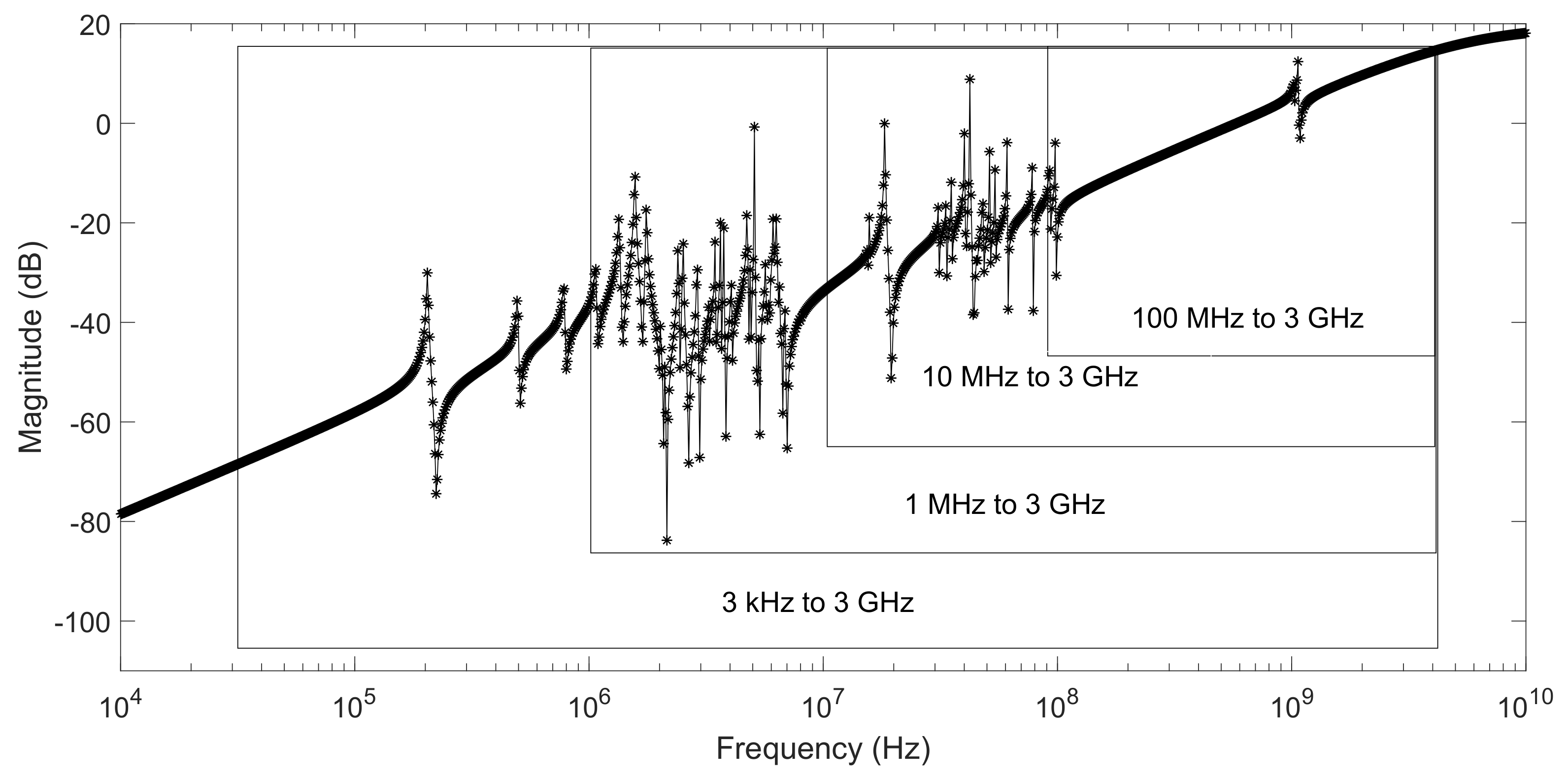
1). For the purpose of checking the accuracy of our proposed RNSZ method, we generated examples of an order 79 and 1079 RLC network and interconnect bus respectively. In addition, we also take a look at series of examples of on-chip spiral inductor with transfer function ranging from few kHz to GHz. The examples covers the frequency ranges of 3 kHz to 3 GHz, 1 MHz to 3 GHz, 10 MHz to 3 GHz and 100 MHz to 3 GHz to discuss some limitations of the proposed RNSZ method. The results discussed at the end of this section highlight that RNSZ is suitable for application specific solution and its use may be restricted only for narrow-band high-speed ICs applications.
Firstly, we took the example of a low order 79 RLC network and compared the reduce order modeling result of PRIMA [
19] and interpolation via SZ [
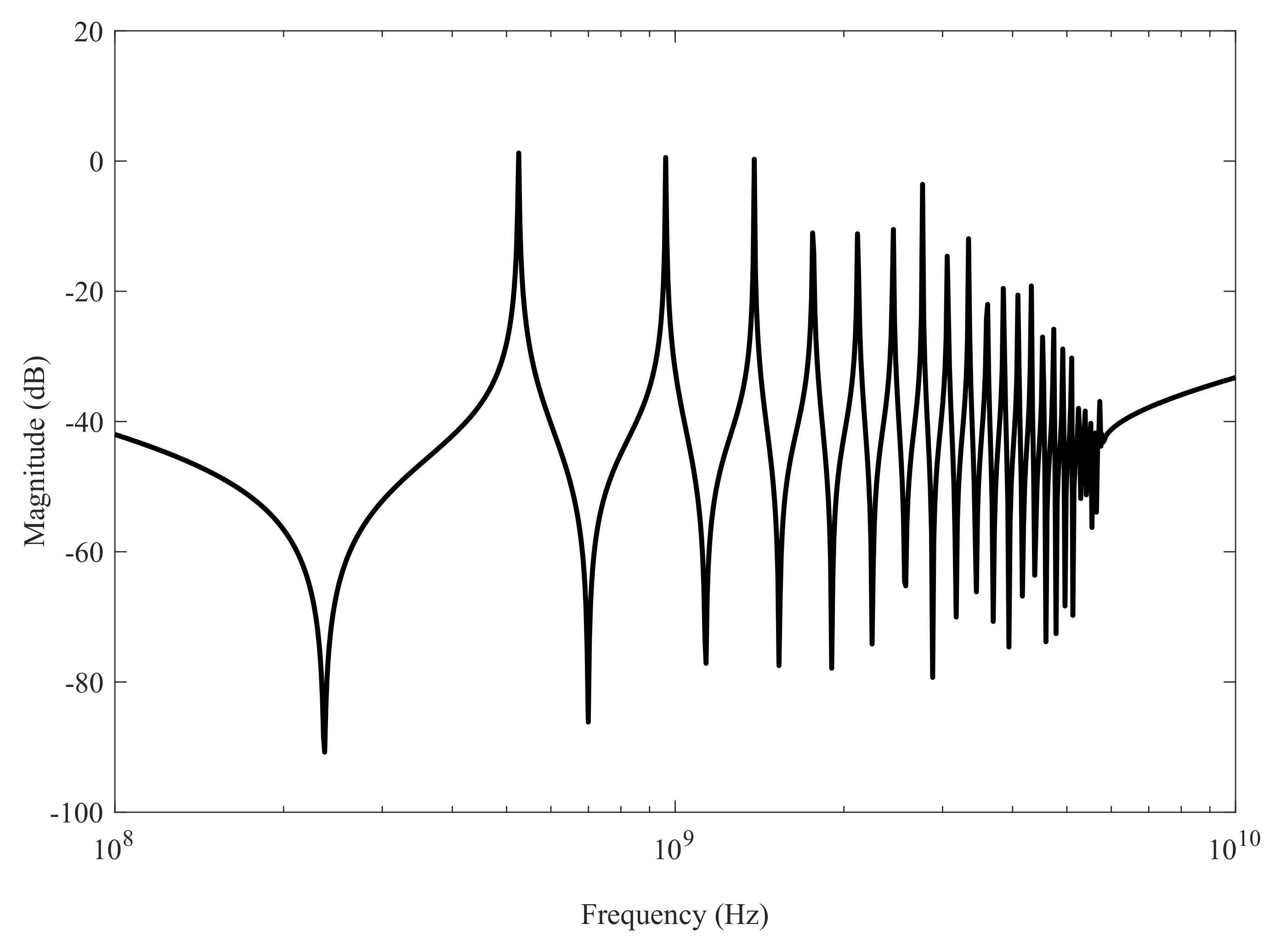
37] with RNSZ method. The original system of RLC network is plotted in
Figure 2. The comparison results in
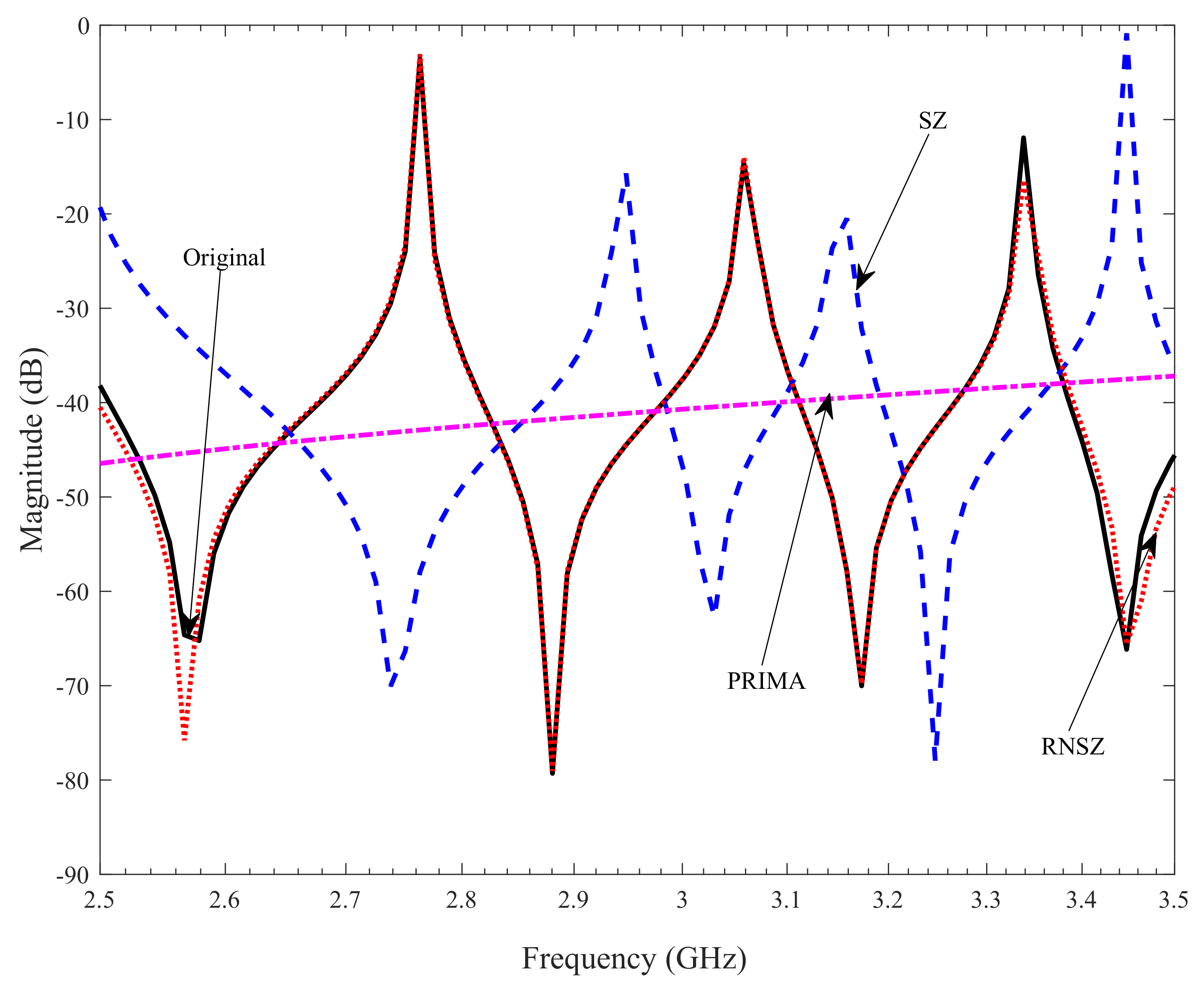
Figure 3 and
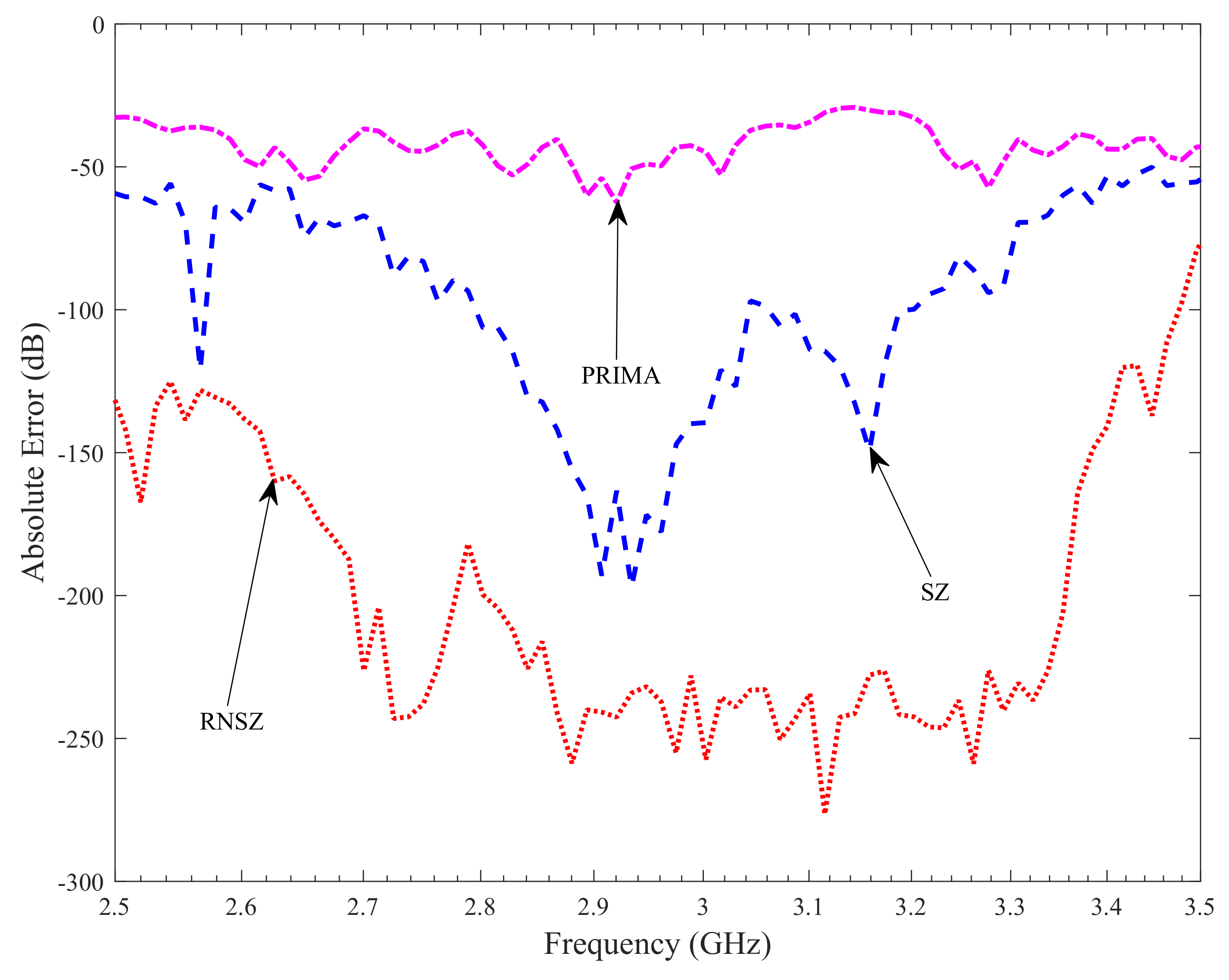
Figure 4 (projection showing selected frequency of interest from 2.5 GHz to 3.5 GHz) shows a close match of RNSZ, with an overlapping peaks and response compared to the original system. However, a significant deviation is observed in case of SZ method using interpolation at selected spectral zeros and PRIMA. A comparison of the absolute error in dB is plotted in
Figure 5. The error plot shows that our proposed method of RNSZ method has considerably reduce error relative to the PRIMA and interpolation via SZ.
In order to compare complexity for large span of frequency, we also plotted the same RLC network example by increasing the span from 2 GHz to 3.5 GHz in
Figure 6. In this case, note that the number of states required by RNSZ method doubled from N = 10 to 20. It is observed that the complexity of the amplitude response and the desired minimum error will determine the order of ROM, which considerably varies from example to example. The presence of resistor, inductor and capacitor in on-chip interconnect makes the response oscillatory and unique to each examples. The number of oscillation peaks and bottoms in a particular span of frequency is directly proportional to the complexity of the ROM of system. A higher order example of spiral inductor covering a large span of frequency, i.e., from 1.5 GHz to 3.5 GHz is discussed at the end of this section.
The second example is a state space model of an interconnect bus. The initial system response of the bus is plotted in
Figure 7. The example is taken, keeping in mind the state of art the processor. The extraction tools creates this example keeping in mind Intel Core i7-2920XM modern processor [
46]. Note that i7-2920XM works on two frequencies, i.e., 2.5 GHz and 3.5 GHz, which actually defines the frequency of interest in this simulation.
Figure 8 displays the magnitude response of original n = 1076 order interconnect bus, with reduced order N = 100 response using PRIMA [
19], SZ [
37] and proposed RNSZ method.
The result of the comparison in
Figure 8 and
Figure 9 shows that a reduce order 100 using proposed RNSZ method correctly captures the behaviour of the system. However, the PRIMA implementation misses most of the resonance peaks and does not accurately characterize the original system response. It is observed that the Arnoldi based PRIMA matches the low frequency response first and a reduced order 100 is not sufficient to accurately cover the selected frequency range. The error plot shown in
Figure 10 highlights the strength of our proposed method (RNSZ) showing the minimum error over the entire range of frequency, i.e., from 2.5 GHz to 3.5 GHz. Note that the reduce error is due to the dynamical selection of SZs based on reduce-norm criterion proposed in
Section 3. The selection of SZ methods based on interpolation at the selected spectral zeros [
37] performs better than PRIMA. However,
Figure 10 shows that the calculated mean absolute error for the interconnect bus in the frequency of interest is −180.52 dB, −112.93 dB and −42.61 dB for the RNSZ, SZ and PRIMA methods respectively.
In order to show that the proposed RNSZ also works well with large span of frequency, we selected an on-chip spiral inductor example. The original system of order n = 1008 along with ROM of order N = 50 produced by RNSZ and PRIMA methods are plotted in
Figure 11. The results clearly show a close match of RNSZ method. However, the PRIMA method show deviations of the magnitude plot compared to original system and missed out most of the peaks of the system transfer function. The simulation example clearly show validity of the proposed RNSZ method for large span of frequency. Note that the order and hence the number of states required to represent the ROM will increase with large frequency of interest and a more complex example.
A comparison of the mean absolute error of the ROM generated by the proposed RNSZ, PRIMA and SZ methods are tabulated in
Table 1. The calculated mean absolute errors for the RLC network and Interconnect bus shows that the proposed RNSZ correctly captures the behaviour of the system with almost negligible error.
In the end, we take series of examples generated from an on-chip spiral inductor with transfer function spanning from few kHz to GHz range as shown in
Figure 12. In first example, we take the frequency range from 100 MHz to 3 GHz and plot the original and ROM function (order n = 38) in
Figure 13. In this simulation, we selected lower and upper range of frequencies to be 100 MHz and 3 GHz respectively. The absolute error plot in
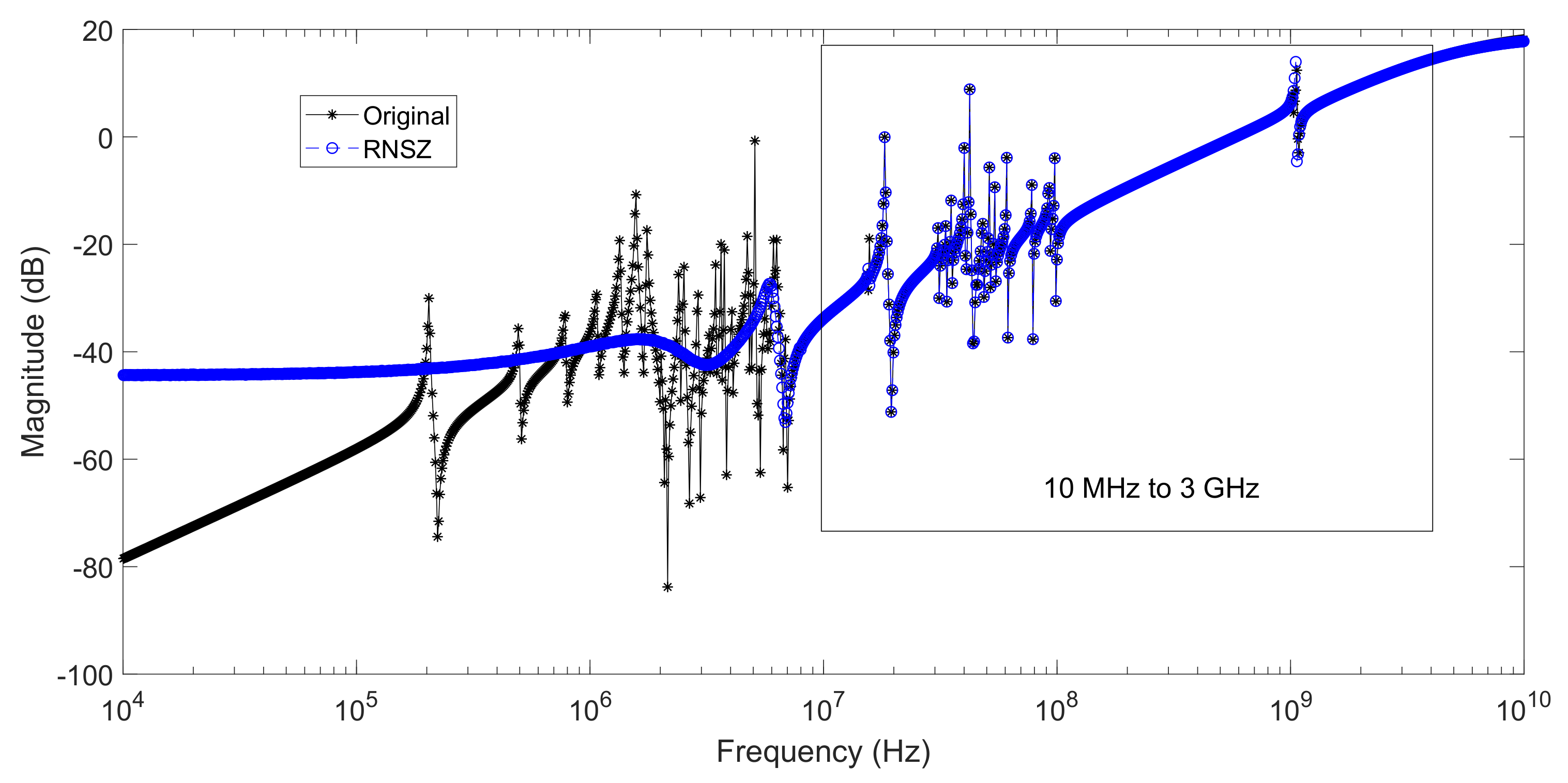
Figure 14 shows a close match with a mean absolute error of −129.98 dB in the selected range of frequencies. The second example is the same spiral inductor, however this time, we selected the lower and upper range of frequencies to be 10 MHz and 3 GHz respectively. The simulation results are plotted in
Figure 15, which shows a close match with ROM of order n = 50 computed using RNSZ method. The absolute error is shown in
Figure 16 with a mean absolute error of −100.97 dB in the selected range of frequencies. It is important to note that these two examples cover narrow band of frequencies and their simulation results shows overlapping peaks with their mean absolute error less than −100 dB.
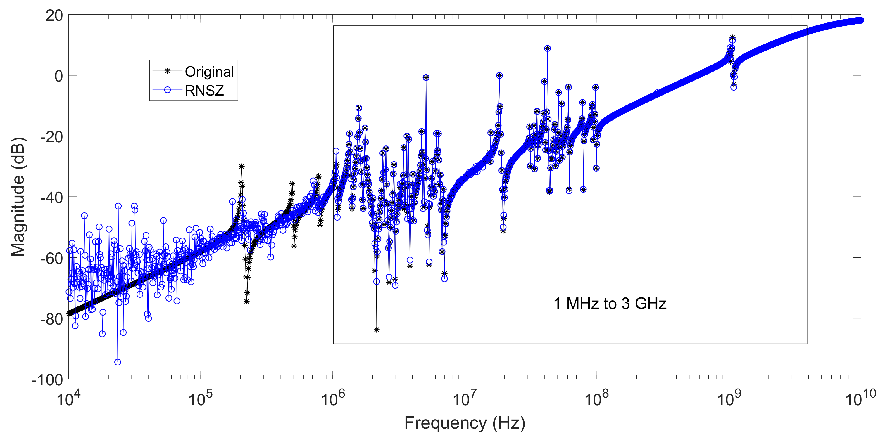
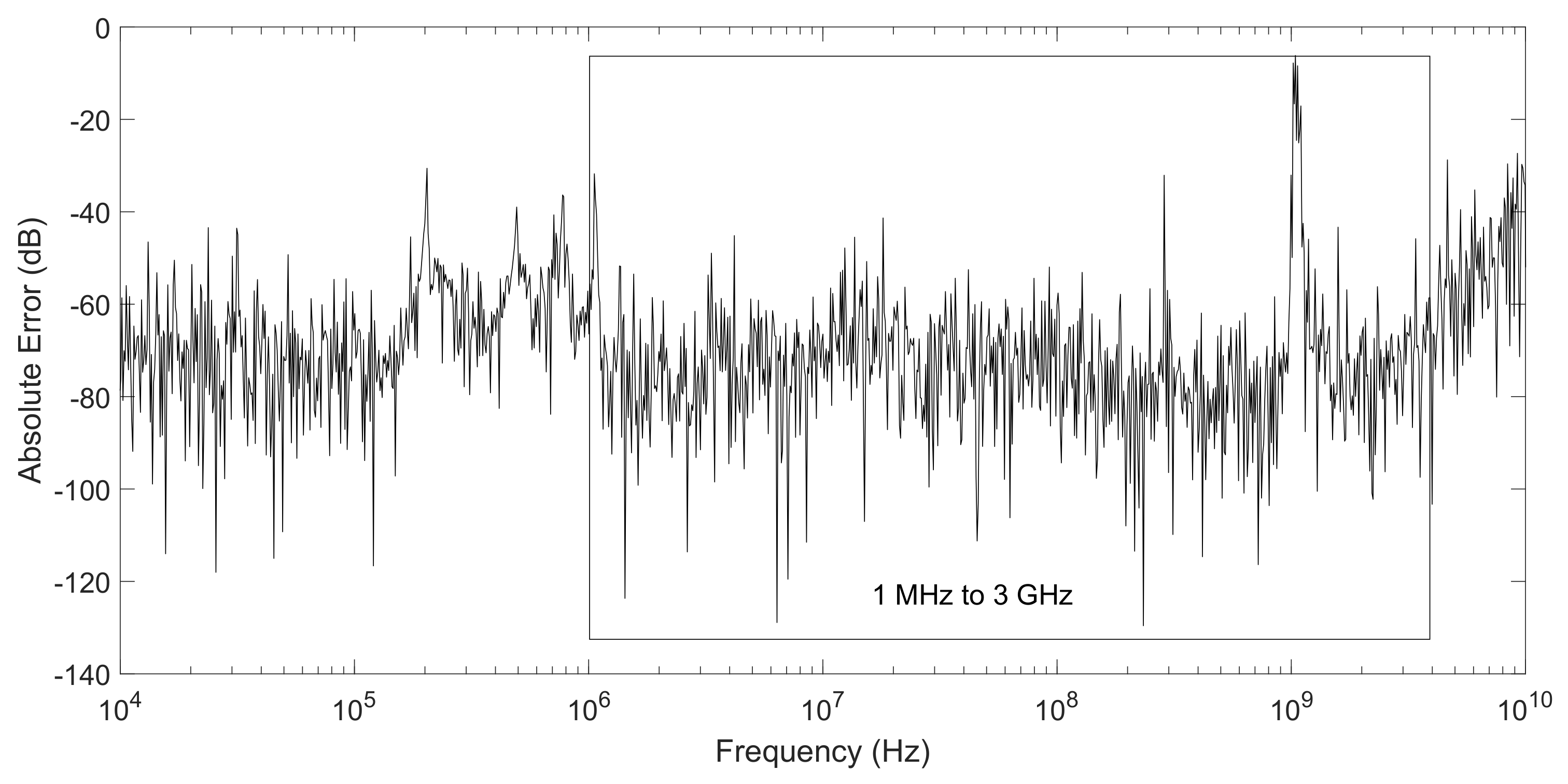
In order to gain good inside of the problem related with large band of frequencies, the next two examples are spread over a large span of frequencies, i.e., 1 MHz to 3 GHz and 3 kHz to 3 GHz. In third example we selected lower and upper range of frequencies to be 1 MHz and 3 GHz respectively. The simulation results are plotted in
Figure 17 with a reduce order of n = 180 matching the original frequency response. It is worth mentioning here that ROM order in this case is quite high, almost comparable to the order of the original system. Therefore, the example highlights that the proposed RNSZ techniques is not suitable for large span of frequencies. The absolute error plot in
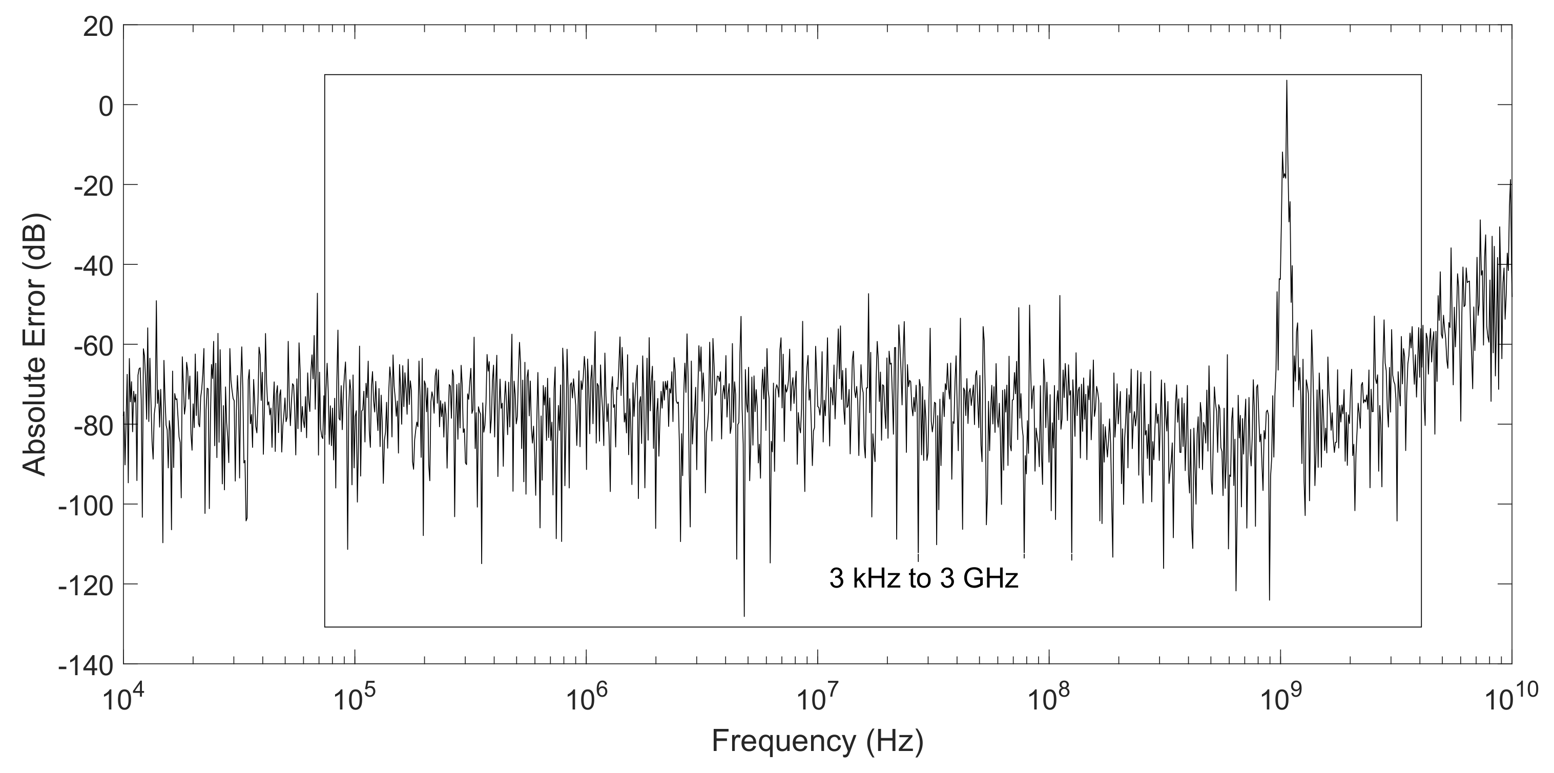
Figure 18 shows a good match with a mean absolute error of −73.98 dB in the selected range of frequencies. The fourth and last example is for a frequency range of 3 kHz to 3 GHz. The simulation results are plotted in
Figure 19 and again a very high reduce order of n = 186 is required to match the original frequency response. The absolute error plot in
Figure 18 shows a good match with a mean absolute error of −76.29 dB in the selected range of frequencies.
In the end,
Table 2 summarizes the results to compare accuracy of RNSZ simulation over large band of frequencies. The on-chip spiral inductor example, with transfer function plotted in
Figure 12, spans frequencies from few kHz to GHz. Its simulation results are plotted from
Figure 13,
Figure 14,
Figure 15,
Figure 16,
Figure 17,
Figure 18,
Figure 19 and
Figure 20 and are included in
Table 2. The table compares ROM accuracy and complexity for different range of frequencies.
It is important to note that for large span of frequencies (row 1 and 2 of
Table 2), the order of the ROMs are quite high, which signifies no real advantage gain by model order reduction of the original system. However, for small span of frequencies (row 3 and 4 of
Table 2), the results of RNSZ method gives greater accuracy with fairly small ROMs in addition to guaranteeing stability and passivity of systems. The results discussed in this section and
Table 2 clearly highlight the fact that RNSZ is very efficient for application specific solutions, i.e., for narrow band of frequency with span ranging in few GHz and its use may be restricted only for high-speed applications.

