Abstract
A crucial step in order to achieve fast and low-energy switching operations in resistive random access memory (RRAM) memories is the reduction of the programming pulse width. In this study, the incremental step pulse with verify algorithm (ISPVA) was implemented by using different pulse widths between 10 s and 50 ns and assessed on Al-doped HfO 4 kbit RRAM memory arrays. The switching stability was assessed by means of an endurance test of 1k cycles. Both conductive levels and voltages needed for switching showed a remarkable good behavior along 1k reset/set cycles regardless the programming pulse width implemented. Nevertheless, the distributions of voltages as well as the amount of energy required to carry out the switching operations were definitely affected by the value of the pulse width. In addition, the data retention was evaluated after the endurance analysis by annealing the RRAM devices at 150 °C along 100 h. Just an almost negligible increase on the rate of degradation of about 1 A at the end of the 100 h of annealing was reported between those samples programmed by employing a pulse width of 10 s and those employing 50 ns. Finally, an endurance performance of 200k cycles without any degradation was achieved on 128 RRAM devices by using programming pulses of 100 ns width.
1. Introduction
Resistive random access memory (RRAM) devices have gathered in recent years notable interest in the domain of future non-volatile memories (NVMs) [1]. This technology is seen as a potential replacement of FLASH technology due to its high-density integration, fast switching, low-energy consumption, excellent endurance, long data retention and full compatibility with the CMOS fabrication flow [2,3]. The basic structure of RRAM cells is a metal-insulator-metal (MIM) stack, whose electrical resistance can be switched by changing specific properties of the insulator layer [4]. In RRAM technology based on HfO insulators the resistance switching is based on the formation and disruption of nanometer scale conductive filaments (CFs), which are constituted by oxygen vacancies (V) [5]. In order to establish for the first time the CFs creating a closed route across the insulator, which connects the two metallic electrodes, a first stage, referred as forming operation, is required. This stage drives the device into a conductive state known as low resistive state (LRS) [6]. During the reset operation the CF is disrupted and the device driven into the high resistive state (HRS). Subsequent re-creations of the CF, which drive the device back to LRS are known as set operations.
In order to achieve fast and low-energy switching operations in RRAM memories it is imperative to downscale the width of the voltage pulses used for programming [7,8,9,10,11]. Nevertheless, such a decrease must not deteriorate the reliability and performance regarding endurance and data stability at high temperature [12,13]. The remarkable reduction of the device-to-device (DTD) variability as well as the impact on the endurance and data retention performance achieved by combining the doping of the dielectric HfO layer with an Al concentration of about 10% and the use of an optimized programming algorithm was already proved [14,15]. However, this good performance was achieved by using a quite large pulse width for programming, that is, 10 s. In a previous paper [16], different programming pulse widths were already assessed by working with the incremental step pulse with verify algorithm (ISPVA) with regard to endurance cycling and data retention performance, beginning from 10 s down to 50 ns. In this work, those results are illustrated together with a meaningful extension. The energy consumption per switching operation was calculated for each pulse width considered. Once the pulse width with the best behavior was found, the endurance performance was further tested with an intensive cycling sequence by using this pulse width.
2. Experimental Description
The RRAM devices characterized in the whole study are 1-transistor-1-resistor (1T1R) cells integrated into 4 kbit memory arrays [16], which are illustrated in Figure 1a. Every 1T1R cell is composed by a select NMOS transistor connected in series to the MIM resistor. The transistor is fabricated in 250 nm BiCMOS technology with L = 0.24 m and W = 1.14 m. The relatively high voltages required during the forming operation (see Figure 2a) makes necessary to integrate a transistor with larger dimensions than the minimum allowed by the technological node. The MIM stack, placed on top of the metal level 2 of the CMOS process, is formed by a TiN/HfAlO/Ti/TiN structure. The HfAlO insulator film was grown by Atomic Layer Deposition (ALD) with a thickness of 6 nm and an Aluminum content of ∼10%. All metal films were deposited by magnetron sputtering with a thickness of 7 nm for the scavenging Ti layer and 150 nm for the TiN bottom and top electrodes. After defining the MIM resistor with an area of approximately 0.4 m, a thin SiN film was grown to protect the RRAM device.

Figure 1.
Micrograph and block diagram of the 4 kbit memory chip and schematic of the 1-transistor-1-resistor (1T1R) cells integrated into the array (a) [17]. Schematic illustration of the voltage waveform of the incremental step pulse with verify algorithm (ISPVA) (b) [18].
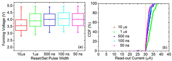
Figure 2.
Box plots of forming voltages (a) and cumulative distribution functions (CDFs) of the currents measured just after the set transition (b) for the initial programming stage. Every box/CDF refers to one batch of 128 RRAM devices labeled with the pulse width value employed for the reset/set operations.
The electrical characterization of the RRAM samples was carried out by using an ad hoc designed memory tester, namely, Active Technologies RIFLE SE. The ISPVA approach is implemented in this set-up by means of software routines programmed in LabVIEW. In such a programming approach a sequence of increasing voltage amplitude pulses is applied to the samples (Figure 1b) [19]. During the forming and set operations the sequence of pulses is applied on the bit line (BL), while along the reset operations this sequence is applied on the source line (SL) (Figure 1a). Just after applying one programming pulse a read-verify procedure is carried out by using a read-out pulsed voltage of 0.2 V on the BL in order to test the resistive state of the RRAM samples programmed. Through forming and set operations, the LRS is achieved when the read-out current measured overcomes a target value of 30 A. In order to control the maximum current that flows through the RRAM device, a voltage value of 1.4 V is imposed on the word line (WL). Through reset operations, the HRS is achieved when the read-out current measured cross down a target value of 5 A. The voltage value applied on the WL in this case is 2.7 V to minimize the transistor series resistance. In this study, five different programming pulse widths were used, namely, 10 s, 1 s, 500 ns, 100 ns and 50 ns (the physical limit imposed by the characterization set-up). The read-out pulse width was fixed to 1 s (also imposed by the set-up) for all experimental tests.
3. Results and Discussion
The creation for the first time of a stable CF in the insulator film of the RRAM samples under study relies on a preliminary stage of forming, reset and set operations performed as shown in [20]. The pulse amplitude sweep during the forming operation ranges from 2 up to 5 V with an amplitude step of 0.01 V and a pulse width value of 1 s. During the reset and set operations a voltage amplitude range from 0.5 up to 3.5 V with a voltage step of 0.1 V was employed. The pulse width values used were those mentioned above in a range between 10 s and 50 ns. The cumulative distribution functions (CDFs) of the current values measured during the set operation just after the target value is overcome are depicted in Figure 2b for the five different batches of 128 RRAM devices, each one assessed with one of the five pulse width values considered. No significant differences can be found among the five current CDFs with respect to the pulsed width employed for this preliminary programming stage.
Afterwards, 1k reset/set cycles were performed on every batch of 128 RRAM devices in order to test the switching endurance for every pulse width considered. As shown in Figure 3, it can be concluded that the voltage amplitude required to switch the RRAM devices increases when the programming pulse width is reduced [21,22]. This increase is even more noticeable when pulse widths of 100 and 50 ns are used. For these specific values, it does not only take place a shift in the mean value of the CDF to higher voltage values, but also a tail appears at the top end of the CDF. In summary, by reducing the programming pulse width the voltage amplitudes and, in consequence, the number of pulses required by the ISPVA are increased.
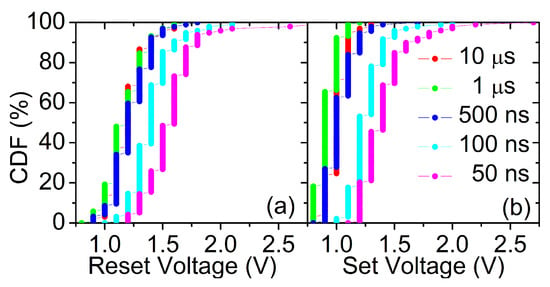
Figure 3.
CDFs of the reset (a) and set (b) voltage amplitudes required by the ISPVA during the first endurance cycle regarding to the programming pulse width used: 10 s, 1 s, 500 ns, 100 ns and 50 ns.
In order to decide whether this voltage increase is compensated by the reduction of the pulse width, in this extension of [16] the average energy required to carry out set and reset operations on a single RRAM device has been estimated as [23]:
where N is the average number of steps performed during the corresponding ISPVA operation, is the voltage amplitude of the programming pulse applied at step i, is the current flowing through the 1T1R RRAM cell at step i, is the width of the programming pulse (10 s, 1 s, 500 ns, 100 ns or 50 ns), = 0.2 V is the read-out voltage applied during the verify operation, is the current measured through this operation at step i and = 1 s is the read-out pulse width. It is important to point out the main limitations associated to this estimation method. First of all, although the 1T1R RRAM cells are integrated in a memory chip, the energy consumption estimated does not include the energy associated to the peripheral circuitry, just the energy consumed by the 1T1R cell itself. Secondly, the memory tester does not provide the current values that flow through the RRAM device when the programming pulses are applied (), hence, it is necessary to estimate these values from the read-out current values measured () by assuming a linear increase with the voltage amplitude for LRS and the quantum point contact (QPC) dependency for HRS [24]. Finally, and are assumed to be constant during the whole pulse width and , respectively.
In Figure 4 the energy consumption associated to programming and read-out pulses is plotted independently for both reset and set operations. The energy consumption of the programming pulses is strongly impacted by the pulse width employed. A reduction of more than one order of magnitude takes place by narrowing the pulse width from 10 s to 50 ns: from ∼5 nJ to ∼60 pJ during reset operations and from ∼630 pJ to ∼19 pJ during set operations. The amount of energy required to reset a RRAM cell is clearly larger than that required to set it (Figure 4). This result is in line with previous studies, which suggest a positive feedback (between Joule heating and the current increase) during the set operation and a negative feedback (between the gap size in the CF and the current decrease) during the reset operation [25]. Furthermore, the energy consumption coming from the read-out operations (Figure 4) remains almost constant regardless the programming pulse width used considering that the read-out pulse width is kept constant to 1 s. In conclusion, 50 ns programming pulse width seems to be the best option in order to ensure low-energy switching. However, the voltage tail present in the CDF depicted in Figure 3 for this pulse width can make the switching operation not reliable enough for real memory scenarios. As a result, a trade-off remains to determine which programming pulse width guarantees the most reliable and lowest-energy operation.
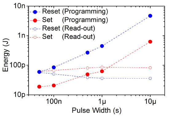
Figure 4.
Average energy required to perform reset (blue dots) and set (red dots) operations on a single 1T1R resistive random access memory (RRAM) cell. The total value is split between the energy associated to programming (solid dots) and read-out (empty dots) pulses.
The reset and set voltage amplitudes at which the effective switching takes place are depicted in Figure 5 for 1k endurance cycles considering every pulse width value. Although the slight reduction featured by the voltage amplitudes with increasing the number of cycles, the switching stability demonstrates to be quite good for every pulse widths considered. By programming with a pulse width of 10 s, it can be observed a small rise of the voltage amplitudes after about 100 cycles. It is possible that this very large pulse width overstress the Al:HfO dielectric film, which makes harder to carry out successful switching operations with raising cycles. The evolution of the mean and dispersion values of the LRS and HRS read-out currents along the endurance test is depicted in Figure 6. LRS and HRS stay stable along the whole 1k cycles regardless the programming pulsed width employed.
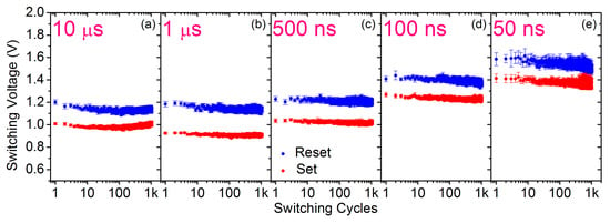
Figure 5.
Mean and dispersion values of switching voltages for reset (blue) and set (red) operations during 1k endurance cycles for every programming pulse width: 10 s (a), 1 s (b), 500 ns (c), 100 ns (d) and 50 ns (e).
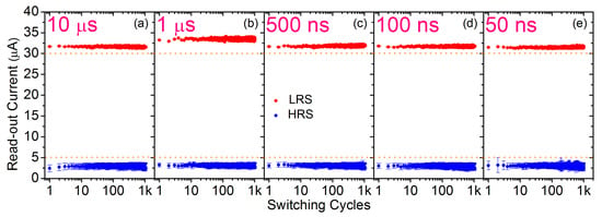
Figure 6.
Mean and dispersion values of read-out currents measured just after the reset (blue) and set (red) transitions during 1k endurance cycles for every programming pulse width: 10 s (a), 1 s (b), 500 ns (c), 100 ns (d) and 50 ns (e).
In order to illustrate better the variability of the LRS and HRS read-out currents measured during the 1k cycles endurance test, the CDFs of each batch of 128 RRAM devices corresponding to each pulse width are shown in Figure 7 for four different cycles sampled in a logarithmic way: 1, 10, 100 and 1k. The DTD variability is essentially the same regardless the number of cycle or the pulse width. HRS current values range from 0.1 A (the resolution of the characterization set-up) up to 5 A (the threshold value imposed by the ISPVA during reset operations). LRS current values range from 30 A (the threshold value imposed by the ISPVA during set operations) up to about 35 A (limited by the select transistor). Such a variation of about 5 A is only slightly overcome working with 1 s pulse width (Figure 7b). This difference can be attributed to the variability existing at the batch level, already noticeable after the forming stage (Figure 2b).
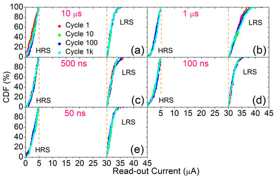
Figure 7.
CDFs of read-out currents measured just after the reset (HRS) and set (LRS) transitions during 1k endurance cycles (logarithmically sampled: 1, 10, 100 and 1k cycles) for every programming pulse width: 10 s (a), 1 s (b), 500 ns (c), 100 ns (d) and 50 ns (e).
In addition, in order to fully assess the reliability of the conductive states programmed by using the five different pulse widths, the data retention was evaluated after the endurance cycling by annealing the RRAM devices at 150 °C along 100 h. As reported in [14], the HRS stays almost imperturbable at high temperatures, hence, only the LRS was tested. The evolution of the read-out currents measured at 0, 1, 10 and 100 h sampling times are shown in Figure 8. The variation from the initial values at 0 h (Read-out) were plotted. As an extension of [16], the CDFs of such read-out currents are illustrated in Figure 9. Shorter programming pulse widths show a slightly larger rate of data degradation. Nevertheless, the difference in average at the end of the annealing (100 h) between 10 s and 50 ns pulse widths is as small as ∼1 A. Therefore, the thermal stability is not harmed by the use of shorter pulse widths during the programming operations.
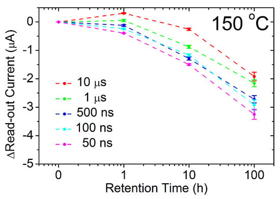
Figure 8.
Variation of the mean and dispersion values of read-out currents sampled during the retention test compared to the ones obtained at the beginning of the annealing at 150 °C for every programming pulse width.
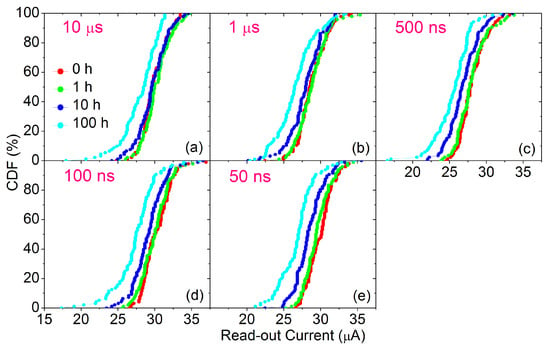
Figure 9.
CDFs of read-out currents sampled after 0, 1, 10 and 100 h of annealing at 150 °C during the retention test for every programming pulse width: 10 s (a), 1 s (b), 500 ns (c), 100 ns (d) and 50 ns (e).
In conclusion, by using shorter programming pulse widths in order to accomplish fast and low-energy switching operations no significant endurance or data retention issues are reported. Such a good performance achieved regardless the pulse width employed could be explained as follows. According to Balatti et al. [21], there is an optimal combination of the programming pulse width and the voltage amplitude in order to achieve the best switching endurance. The step-by-step approach implemented in the core of the ISPVA leads to a dynamic tailoring of this combination of the two programming parameters (see Figure 3) every cycle. Thus, the best endurance performance can be achieved whatever is the pulse width selected within the studied range. Regarding retention performance, Chen et al. [26] concluded that the stability of the CF is really impacted by the pulse width employed during the programming of the RRAM cells, while in the current study the impact was found to be almost negligible (see Figure 8). This difference could be attributed to the lack of SiN encapsulation of the MIM stack in [26], which has been reported as an effective strategy to suppress the chemical interaction between the MIM cell and the environment, strongly reducing, hence, the retention issues [27].
Based on the trade-off previously mentioned between switching energy consumption reduction (Figure 4), by using a narrower programming pulse width, while keeping a reliable operation on RRAM arrays, in particular, keeping under reasonable limits the dispersion of switching voltages (Figure 3), 100 ns pulse width was considered as the best value to extend the assessment of the endurance performance on the 4 kbit RRAM arrays. In order to reduce as much as possible the execution time of the endurance test, the voltage sweeps of programming pulses amplitude during ISPVA were tailored to the voltage CDFs shown in light blue in Figure 3: from 1.0 to 2.2 V during reset operation and from 0.8 to 2.0 V during set operation. The execution time was further reduced by increasing the voltage step in the IPSVA from 0.1 V to 0.2 V.
Under these conditions a more intensive cycling sequence was carried out on 128 RRAM cells up to 200k reset/set switching operations. Figure 10a,b show, respectively, the average and dispersion of switching voltages and read-out currents measured just after the resistance transition in a logarithmic sampling way. Apart from the slight decrease of voltages as a function of cycling, already present on 1k cycles tests, and some minor fluctuations, the switching operation demonstrates a quite good stability for the whole cycling process. In addition, LRS and HRS conductive levels remain beyond the current limits imposed by the ISPVA without any degradation. This fact can be further tested in Figure 11, where the CDFs of the LRS and HRS read-out currents are depicted for seven different cycles sampled as follows: 1, 10, 100, 1k, 10k, 100k and 200k. The DTD variability remains the same compared with the CDFs shown in Figure 7, even after 200k cycles.
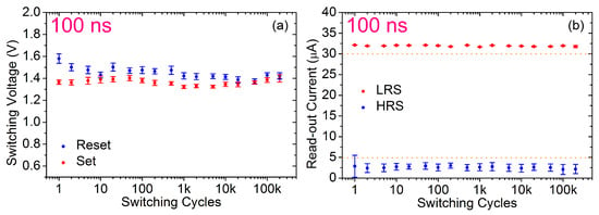
Figure 10.
Mean and dispersion values of switching voltages (a) and of read-out currents (b) gathered just after the reset (blue) and set (red) transitions during an endurance test of 200k switching cycles on 128 RRAM devices by using a programming pulse width of 100 ns.
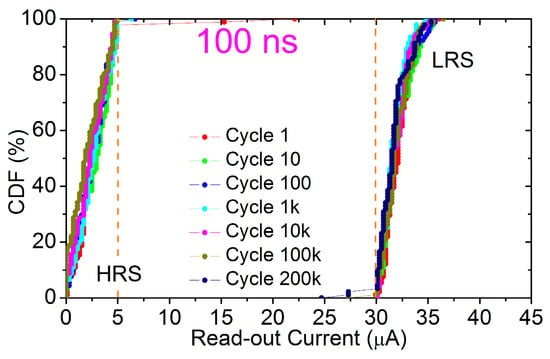
Figure 11.
CDFs of read-out currents measured just after the reset (HRS) and set (LRS) transitions during an endurance test of 200k switching cycles on 128 RRAM devices by using a programming pulse width of 100 ns.
4. Conclusions
The influence of the decrease of the programming pulse width on the performance and reliability of Al:HfO-based 4 kbit RRAM memories has been assessed. In a preliminary study an endurance test of 1k switching cycles was performed. The switching performance of both LRS and HRS was not harmed by reducing the programming pulse width from 10 s down to 50 ns. Nevertheless, the voltage amplitudes necessary to program the RRAM samples were clearly affected. Despite of the nominal decrease of the programming time due to the pulse width reduction, the amplitude and number of ISPVA pulses needed to carry out successfully a switching transition are raised. In order to better assess this trade-off, the energy required to set and reset RRAM cells was calculated in this work for each programming pulse width. In addition, the reduction of the programming pulse width does not compromise the data retention even after 100 h of 150 °C annealing. Therefore, there are no endurance or data stability issues linked to the implementation of fast and low-energy programming operations in the Al:HfO-based RRAM memory chips. Finally, a quite stable endurance performance by using a programming pulse width of 100 ns was demonstrated during 200k cycles on 128 RRAM devices with no relevant degradation either on switching voltages or on LRS and HRS read-out currents.
Author Contributions
E.P. and Ó.G.O. wrote the original manuscript; Ó.G.O. performed the electrical characterization of the samples; E.P. performed the analysis of the data; S.D., H.C. and C.W. administered and supervised the projects involved; S.D., H.C., H.G. and C.W. assisted in reviewing and editing the manuscript. All authors have read and agreed to the published version of the manuscript.
Funding
This research was funded by the Spanish Ministry of Science and the FEDER program through projects TEC2017-84321-C4-3-R and MTM2017-88708-P as well as by the German Research Foundation (DFG) in the frame of research group FOR2093. The publication of this article was funded by the Open Access Fund of the Leibniz Association.
Acknowledgments
We would like to thank Cristian Zambelli, Piero Olivo (University of Ferrara) and Alessandro Grossi (Infineon Technologies) for providing support in terms of ISPVA implementation in the RIFLE SE memory tester.
Conflicts of Interest
The authors declare no conflict of interest.
References
- Ielmini, D. Resistive switching memories based on metal oxides: Mechanisms, reliability and scaling. Semicond. Sci. Technol. 2016, 31, 063002. [Google Scholar] [CrossRef]
- Lee, H.Y.; Chen, P.S.; Wu, T.Y.; Chen, Y.S.; Wang, C.C.; Tzeng, P.J.; Lin, C.H.; Chen, F.; Lien, C.H.; Tsai, M.-J. Low power and high speed bipolar switching with a thin reactive Ti buffer layer in robust HfO2 based RRAM. In Proceedings of the 2008 IEEE International Electron Devices Meeting, San Francisco, CA, USA, 15–17 December 2008. [Google Scholar]
- Chen, Y.Y.; Goux, L.; Pantisano, L.; Swerts, J.; Adelmann, C.; Mertens, S.; Afanasiev, V.V.; Wang, X.P.; Govoreanu, B.; Degraeve, R.; et al. Fully CMOS BEOL compatible HfO2 RRAM cell, with low (μA) program current, strong retention and high scalability, using an optimized Plasma Enhanced Atomic Layer Deposition (PEALD) process for TiN electrode. In Proceedings of the 2011 IEEE International Interconnect Technology Conference, Dresden, Germany, 8–12 May 2011. [Google Scholar]
- Jeong, D.S.; Thomas, R.; Katiyar, R.S.; Scott, J.F.; Kohlstedt, H.; Petraru, A.; Hwang, C.S. Emerging memories: Resistive switching mechanisms and current status. Rep. Prog. Phys. 2012, 75, 076502. [Google Scholar] [CrossRef] [PubMed]
- Lin, Y.S.; Zeng, F.; Tang, S.G.; Liu, H.Y.; Chen, C.; Gao, S.; Wang, Y.G.; Pan, F. Resistive switching mechanisms relating to oxygen vacancies migration in both interfaces in Ti/HfOx/Pt memory devices. J. Appl. Phys. 2013, 113, 064510. [Google Scholar] [CrossRef]
- Traore, B.; Blaise, P.; Vianello, E.; Perminola, L.; De Salvo, B.; Nishi, Y. HfO2-based RRAM: Electrode effects, Ti/HfO2 interface, charge injection, and oxygen defects diffusion through experiment and ab initio calculations. IEEE Trans. Electron Devices 2016, 63, 360–368. [Google Scholar] [CrossRef]
- Lee, H.Y.; Chen, Y.S.; Chen, P.S.; Gu, P.Y.; Hsu, Y.Y.; Wang, S.M.; Liu, W.H.; Tsai, C.H.; Sheu, S.S.; Chiang, P.C.; et al. Evidence and solution of over-RESET problem for HfOx based resistive memory with sub-ns switching speed and high endurance. In Proceedings of the 2010 International Electron Devices Meeting, San Francisco, CA, USA, 6–8 December 2010; pp. 19.7.1–19.7.4. [Google Scholar]
- Chien, W.-C.; Lee, M.-H.; Lee, F.-M.; Lin, Y.-Y.; Lung, H.-L.; Hsieh, K.-Y.; Lu, C.-Y. A multi-level 40nm WOX resistive memory with excellent reliability. In Proceedings of the 2011 International Electron Devices Meeting, Washington, DC, USA, 5–7 December 2011; pp. 31.5.1–31.5.4. [Google Scholar]
- Kim, H.; Sah, M.P.d.; Yang, C.; Roska, T.; Chua, L.O. Neural synaptic weighting with a pulse-based memristor circuit. IEEE Trans. Circuits Syst. I 2012, 59, 148–158. [Google Scholar] [CrossRef]
- Eshraghian, J.K.; Kang, S.-M.; Baek, S.; Orchard, G.; Iu, H.H.-C.; Lei, W. Analog weights in ReRAM DNN accelerators. In Proceedings of the 2019 IEEE International Conference on Artificial Intelligence Circuits and Systems (AICAS), Hsinchu, Taiwan, 19–20 March 2019; pp. 267–271. [Google Scholar]
- Azghadi, M.R.; Chen, Y.-C.; Eshraghian, J.K.; Chen, J.; Lin, C.-Y.; Amirsoleimani, A.; Mehonic, A.; Kenyon, A.J.; Fowler, B.; Lee, J.C.; et al. Complementary metal-oxide semiconductor and memristive hardware for neuromorphic computing. Adv. Intell. Syst. 2020, 2, 1900189. [Google Scholar] [CrossRef]
- Fantini, A.; Goux, L.; Clima, S.; Degraeve, R.; Redolfi, A.; Adelmann, C.; Polimeni, G.; Chen, Y.Y.; Komura, M.; Belmonte, A.; et al. Engineering of Hf1-xAlxOy amorphous dielectrics for high-performance RRAM applications. In Proceedings of the 2014 IEEE 6th International Memory Workshop (IMW), Taipei, Taiwan, 18–21 May 2014. [Google Scholar]
- Wang, C.; Wu, H.; Gao, B.; Dai, L.; Deng, N.; Sekar, D.C.; Lu, Z.; Kellam, M.; Bronner, G.; Qian, H. Relaxation effect in RRAM arrays: Demonstration and characteristics. IEEE Electron Device Lett. 2016, 37, 182–185. [Google Scholar] [CrossRef]
- Perez, E.; Grossi, A.; Zambelli, C.; Olivo, P.; Roelofs, R.; Wenger, C. Reduction of the cell-to-cell variability in Hf1-xAlxOy based RRAM arrays by using program algorithms. IEEE Electron Device Lett. 2017, 38, 175–178. [Google Scholar] [CrossRef]
- Perez, E.; Mahadevaiah, M.K.; Zambelli, C.; Olivo, P.; Wenger, C. Data retention investigation in Al:HfO2-based resistive random access memory arrays by using high-temperature accelerated tests. J. Vac. Sci. Technol. B 2019, 37, 012202. [Google Scholar] [CrossRef]
- Ossorio, O.G.; Perez, E.; Dueñas, S.; Castan, H.; Garcia, H.; Wenger, C. Effective Reduction of the Programing Pulse Width in Al:HfO2-based RRAM Arrays. In Proceedings of the Joint International EUROSOI Workshop and International Conference on Ultimate Integration on Silicon, Grenoble, France, 1–3 April 2019. [Google Scholar]
- Perez, E.; Maldonado, D.; Acal, C.; Ruiz-Castro, J.E.; Alonso, F.J.; Aguilera, A.M.; Jimenez-Molinos, F.; Wenger, C.; Roldan, J.B. Analysis of the statistics of device-to-device and cycle-to-cycle variability in TiN/Ti/Al:HfO2/TiN RRAMs. Microelectron. Eng. 2019, 214, 104–109. [Google Scholar] [CrossRef]
- Perez, E.; Grossi, A.; Zambelli, C.; Olivo, P.; Wenger, C. Impact of the incremental programming algorithm on the filament conduction in HfO2-based 1T-1R RRAM arrays. J. Electron Device Soc. 2017, 5, 64–68. [Google Scholar] [CrossRef]
- Grossi, A.; Zambelli, C.; Olivo, P.; Miranda, E.; Stikanov, V.; Walczyk, C.; Wenger, C. Electrical characterization and modeling of pulse-based forming techniques in RRAM arrays. Solid State Electron. 2016, 115, 17–25. [Google Scholar] [CrossRef]
- Perez, E.; Mahadevaiah, M.K.; Zambelli, C.; Olivo, P.; Wenger, C. Characterization of the interface-driven 1st Reset operation in HfO2-based 1T1R RRAM devices. Solid State Electron. 2019, 159, 51–56. [Google Scholar] [CrossRef]
- Balatti, S.; Ambrogio, S.; Wang, Z.-Q.; Sills, S.; Calderoni, A.; Ramaswamy, N.; Ielmini, D. Understanding pulsed-cycling variability and endurance in HfOx RRAM. In Proceedings of the 2015 IEEE International Reliability Physics Symposium, Monterey, CA, USA, 19–23 April 2015; pp. 5B.3.1–5B.3.6. [Google Scholar]
- Chen, C.Y.; Fantini, A.; Degraeve, R.; Redolfi, A.; Groeseneken, G.; Goux, L.; Kar, G.S. Statistical investigation of the impact of program history and oxide-metal interface on OxRRAM retention. In Proceedings of the 2016 IEEE International Electron Devices Meeting (IEDM), San Francisco, CA, USA, 3–7 December 2016; pp. 4.6.1–4.6.4. [Google Scholar]
- Grossi, A.; Zambelli, C.; Olivo, P.; Crespo-Yepes, A.; Martin-Martinez, J.; Rodriguez, R.; Nafria, M.; Perez, E.; Wenger, C. Electrical characterization and modeling of 1T-1R RRAM arrays with amorphous and poly-crystalline HfO2. Solid State Electron. 2017, 128, 187–193. [Google Scholar] [CrossRef]
- Miranda, E.A.; Walczyk, C.; Wenger, C.; Schroeder, T. Model for the resistive switching effect in HfO2 MIM structures based on the transmission properties of narrow constrictions. IEEE Electron Device Lett. 2010, 31, 609–611. [Google Scholar] [CrossRef]
- Ambrogio, S.; Balatti, S.; Gilmer, D.C.; Ielmini, D. Analytical Modeling of oxide-based bipolar resistive memories and complementary resistive switches. IEEE Trans. Electron Devices 2014, 61, 2378–2386. [Google Scholar] [CrossRef]
- Chen, C.Y.; Fantini, A.; Goux, L.; Degraeve, R.; Clima, S.; Redolfi, A.; Groeseneken, G.; Jurczak, M. Programming-conditions solutions towards suppression of retention tails of scaled oxide-based RRAM. In Proceedings of the 2015 IEEE International Electron Devices Meeting (IEDM), Washington, DC, USA, 7–9 December 2015; pp. 10.6.1–10.6.4. [Google Scholar]
- Gu, P.-Y.; Chen, Y.-S.; Lee, H.-Y.; Chen, P.-S.; Liu, W.-H.; Chen, W.-S.; Hsu, Y.-Y.; Chen, F.; Tsai, M.-J. Scalability with silicon nitride encapsulation layer for Ti/HfOx pillar RRAM. In Proceedings of the 2010 International Symposium on VLSI Technology, System and Application, Hsinchu, Taiwan, 26–28 April 2010; pp. 146–147. [Google Scholar]
© 2020 by the authors. Licensee MDPI, Basel, Switzerland. This article is an open access article distributed under the terms and conditions of the Creative Commons Attribution (CC BY) license (http://creativecommons.org/licenses/by/4.0/).